

Page 1
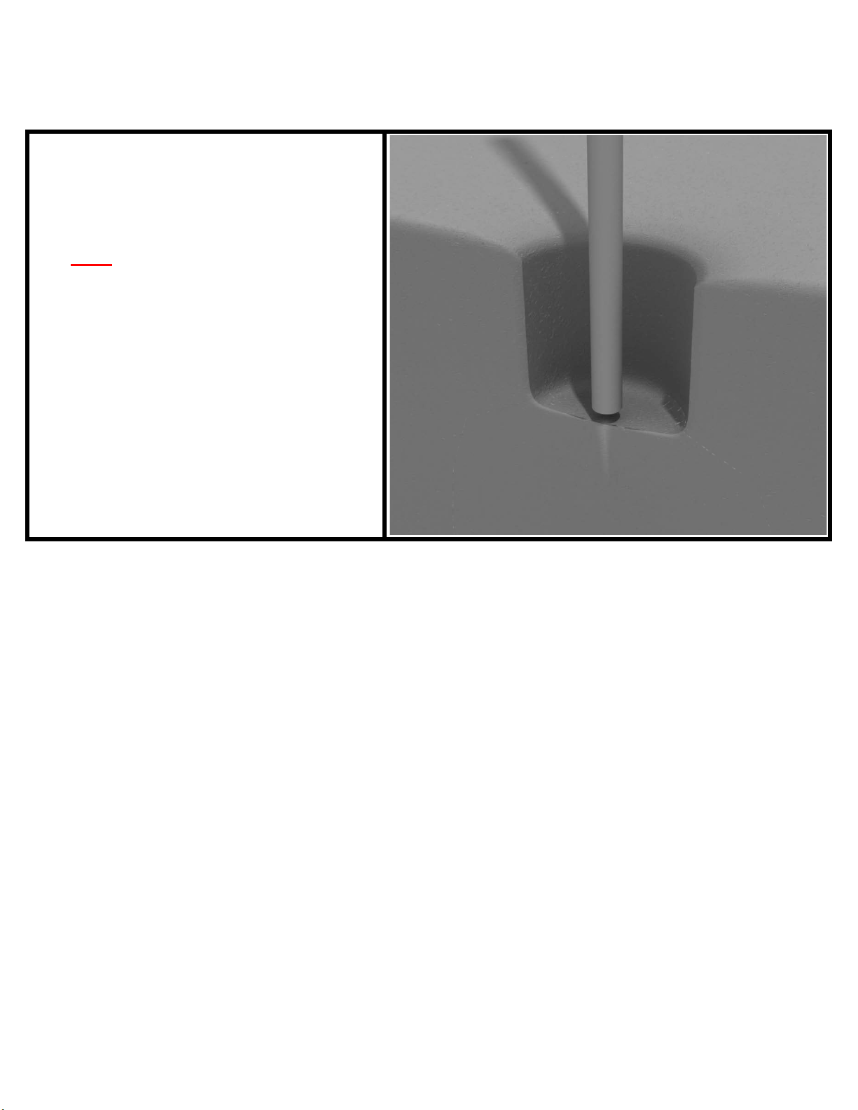
Post Installation
STEP: 1
DO NOT CEMENT POSTS INTO PLACE
UNTIL THE ENTIRE STRUCTURE IS
ASSEMBLED.
Refer to the General Installation
guide footing information and dig
proper holes for the support posts.
10859 Washington
St. Suite 200,
Indianapolis, IN
1-800-667-0097
Created By: Aaron Price
Date: 04/26/2018
Page 1 of 1 (Post Installation)
Page 2
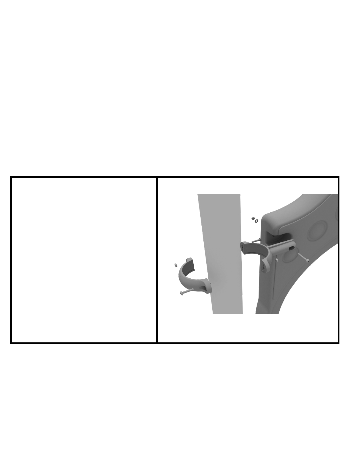
3.5-inch Clamp Installation Examples
The following three pages will include examples of how to install some of the most
common types of Clamps that are present on our structures that use 3.5-inch outside
diameter posts. The structure that you are assembling might not require all the types of
clamps listed in these examples.
T
he Install Guides for specific components that come later in this document might
call for a specific type of clamp (a tube clamp for example), those sections will not include
detailed instructions for the clamps and should direct you back to this section for more
detailed information.
3.
5-inch Flat Clamp Install Example
Connect half of the flat clamp to the
component using one (1) M8*40
bolt. Then, using the other half of the
flat clamp and the hardware
provided in the clamp hardware bag,
attach the backside of the flat clamp
around the post.
10859 Washington St. Suite
200, Indianapolis, IN
1-800-667-0097
Page 1 of 3 (3.5-inch Clamp Installation Examples)
Created By: Derick H
Date: 11/01/2018
Page 3
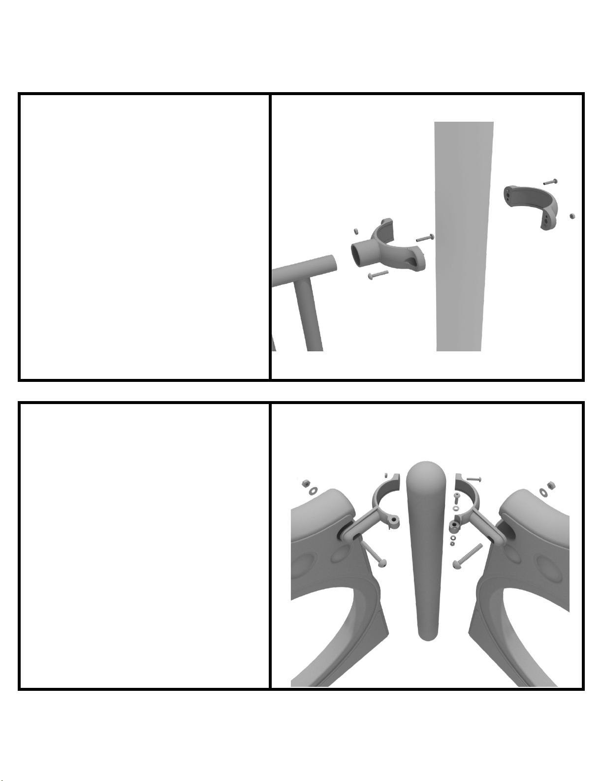
3.5-inch Clamp Installation Examples
3.5-inch Tube Clamp Install Example
Connect half of the clamp to the
component using one (1) M8*30
bolt. Then, using the other half of the
tube clamp and the hardware
provided in the clamp hardware bag,
attach the backside of the tube
clamp around the post.
3.5-inch 90-Degree Flat Clamp Install Example
Connect half of the flat clamp to one
panel using one (1) M8*40 bolt.
Then, using the other half of the flat
clamp and the hardware provided in
the clamp hardware bag, attach the
other half of the tube clamp around
the post. Then, attach the next panel
to the other side of the clamp using
the same process.
10859 Washington St. Suite
200, Indianapolis, IN
1-800-667-0097
Page 2 of 3 (3.5-inch Clamp Installation Examples)
Created By: Derick H
Date: 11/01/2018
Page 4
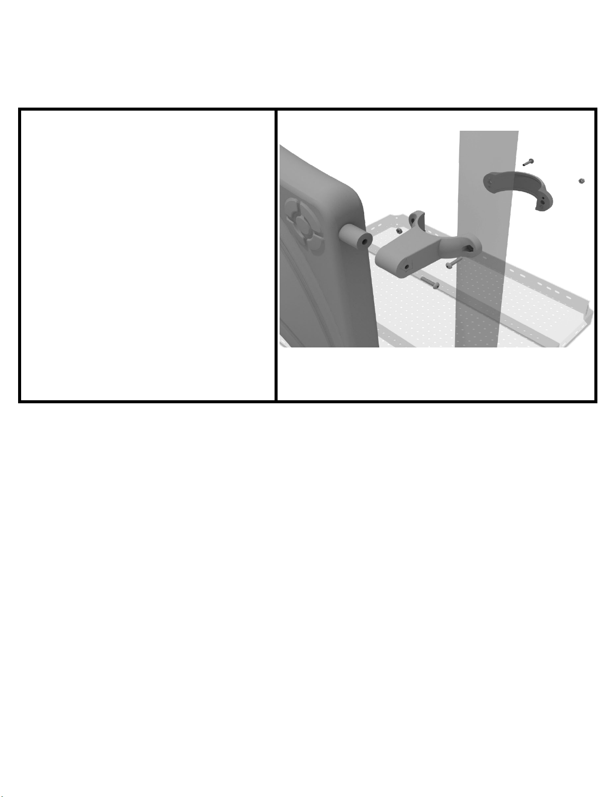
3.5-inch Clamp Installation Examples
3.5-inch Double Slide Clamp Install Example
Connect half of the double slide
clamp to the double slide hood using
one (1) M8*30 bolt. Then, using the
other half of the clamp and the
hardware provided in the clamp
hardware bag, attach the backside of
the double slide clamp around the
post.
10859 Washington St. Suite
200, Indianapolis, IN
1-800-667-0097
Page 3 of 3 (3.5-inch Clamp Installation Examples)
Created By: Derick H
Date: 11/01/2018
Page 5
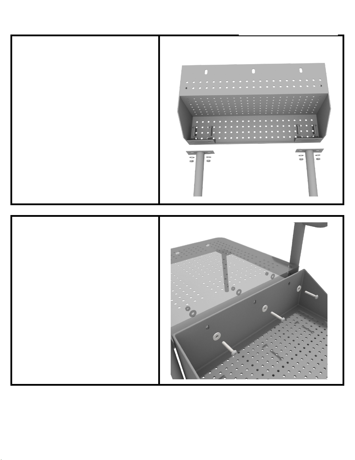
ADA Step Install
STEP: 1
See general installation guide
regarding footing information for the
ADA transfer step mount. Using two
(2) M10 bolts, four (4) M10 washers,
and two (2) M10 lock nuts, attach the
transfer step to each ADA transfer
step mount.
STEP: 2
Using three (3) M10*25 bolts, six (6)
M10 washers, and three (3) M10
washers, attach the top of the ADA
transfer step to the ADA transfer
deck.
10859 Washington St. Suite
200, Indianapolis, IN
1-800-667-0097
Created By: Aaron Price
Date Modified: 3/13/18
Page 1 of 1 (ADA Step Install)
Page 6
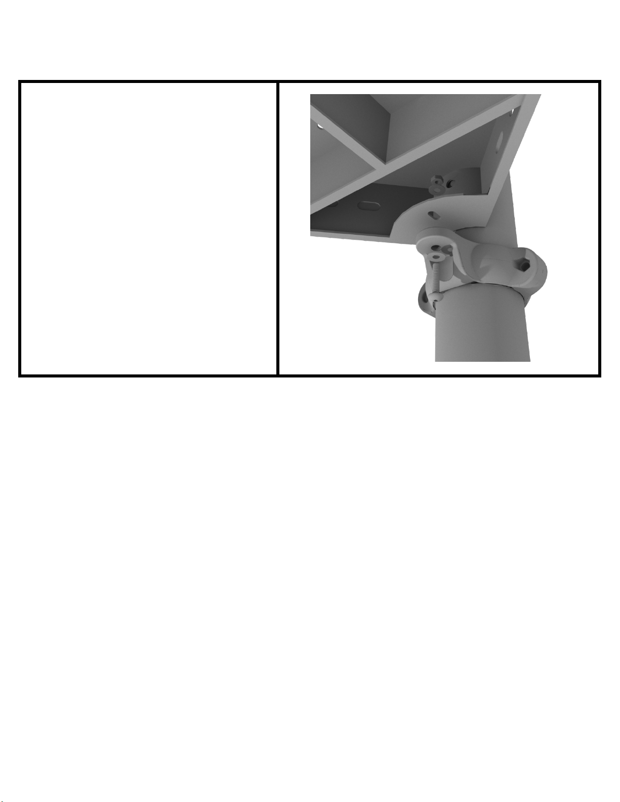
Square Deck Installation
STEP: 1
After the posts are in place, using
four (4) M10*35 Bolts, eight (8) M10
Washers, and four (4) M10 Lock
Nuts, attach each square deck to
each pre-attached deck clamp as
shown in the image.
Deck clamps are pre-attached to the
posts and should not be altered in
any way.
10859 Washington
St. Suite 200,
Indianapolis, IN
1-800-667-0097
Page 1 of 1 (Square Deck Installation)
C
reated By: Aaron Price
Date: 3/19/2018
Page 7
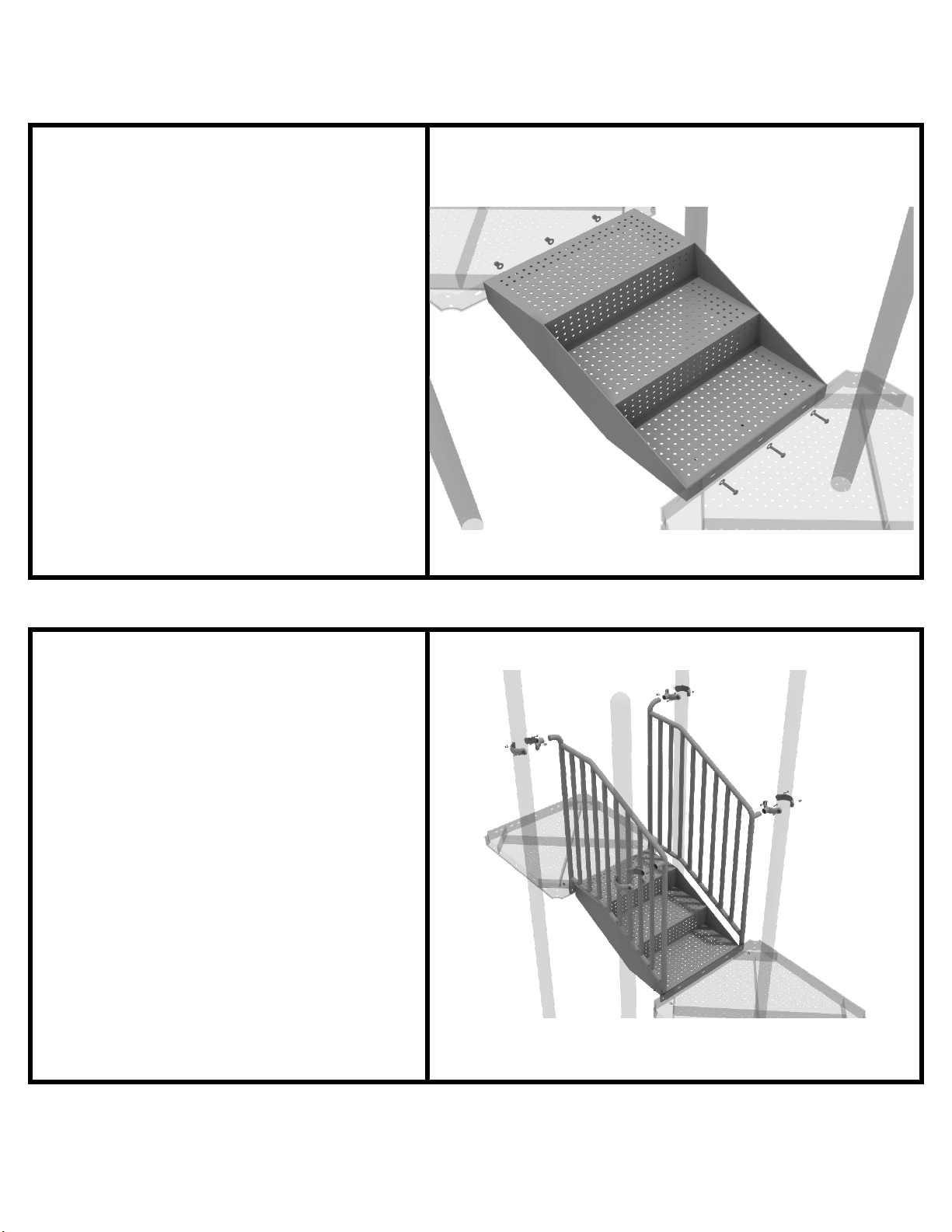
1-Foot Middle Stair Installation
Using eight (6) M10*25 bolts, twelve
(12) M10 washers, and six (6) M10
lock nuts, attach the 12-inch middle
stair to the assigned decks.
Then, once the stair is in place,
attach the 12-inch connection
handrail to the posts using four (4)
3.5-inch tube clamps, and four (4)
M8*30 bolts. Then, attach the
bottom of the handrails to the decks
using one (1) M10*25 bolt, two (2)
M10 washers, and one (1) M10 lock
nut for each attachment point.
STEP: 1
STEP: 2
10859 Washington St. Suite
200, Indianapolis, IN
1-800-667-0097
Page 1 of 1 (1-Foot Middle Stair Installation)
Created By: Aaron Price
Date: 03/29/2018
Page 8
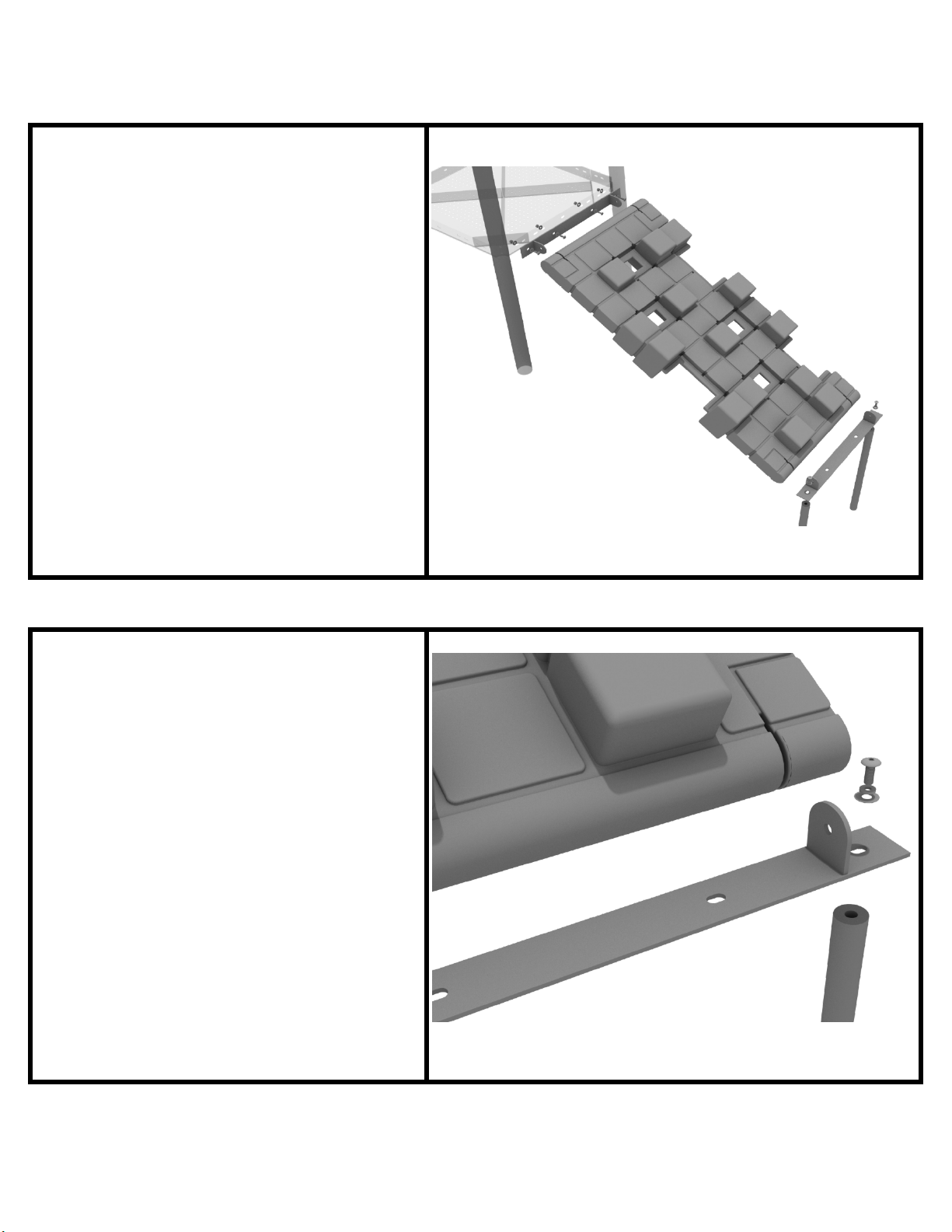
Pixel Climber Installation
STEP: 1
First, detach the pre-attached
bracket on the end of the climber
that has four (4) Bolts attached, and
attach it to the designated deck.
STEP: 2
Then, attach the provided support
mounts to the other side of the Pixel
Climber using the pre-attached bolt.
See general installation guide
regarding footing information for the
figure climber.
10859 Washington St. Suite
200, Indianapolis, IN
1-800-667-0097
Created By: Aaron Price
Date: 04/09/2018
Page 1 of 2 (Pixel Climber Installation)
Page 9
Pixel Climber Installation
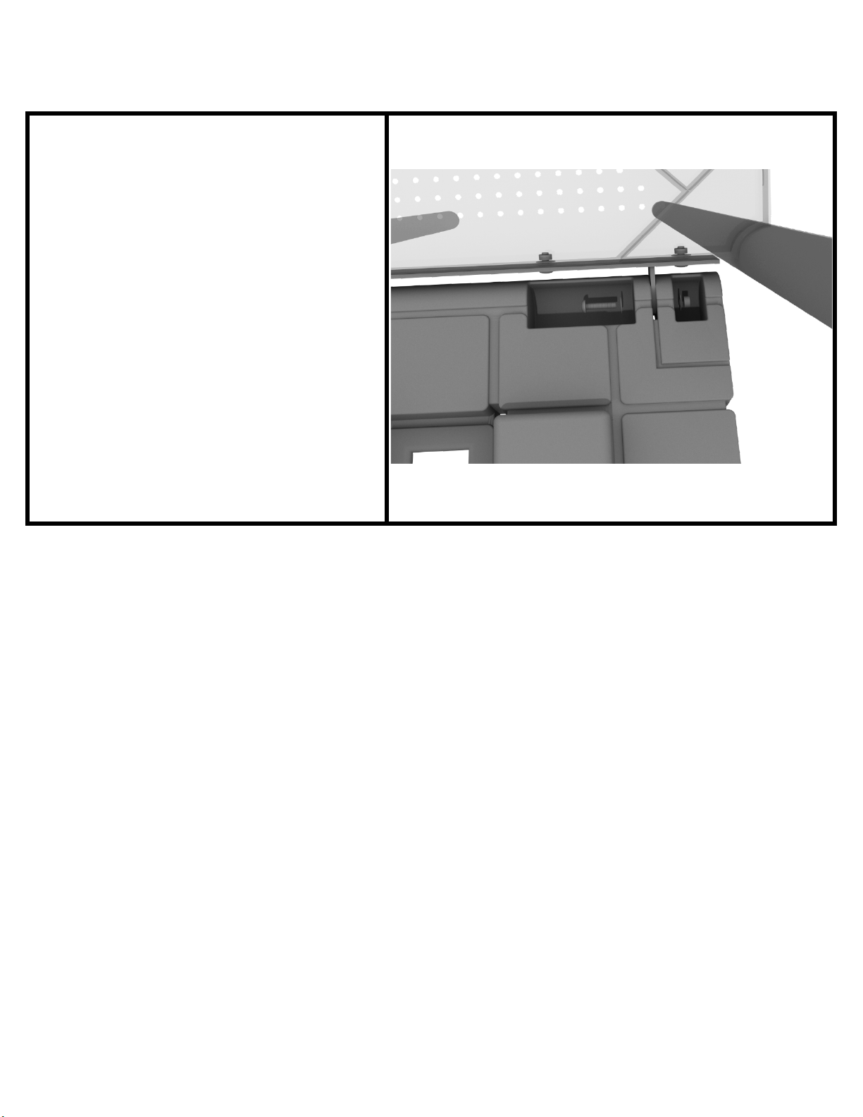
STEP: 3
Finally, attach the climber to the
mount that you attached to the deck
with the pre-attached hardware.
10859 Washington St. Suite
200, Indianapolis, IN
1-800-667-0097
Created By: Aaron Price
Date: 04/09/2018
Page 2 of 2 (Pixel Climber Installation)
Page 10
D-Rail Installation
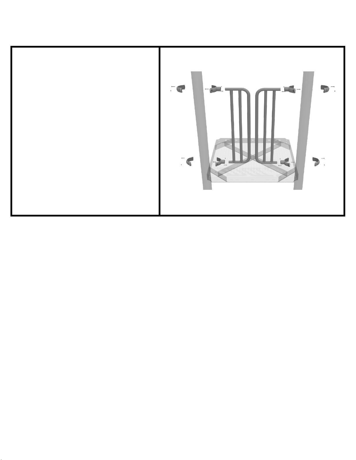
STEP: 1
Take two (2) 3.5-inch tube clamps
and connect half of the clamps both
ends of the D-Rail using one (1)
M8*30 bolt. Then, using the other
half of the tube clamp and the
hardware provided in the clamp
hardware bag, attach the other half
of the tube clamp around the post to
the D-Rail. Repeat this process for
the other D-Rail.
10859 Washington St. Suite
200, Indianapolis, IN
1-800-667-0097
Created By: Aaron Price
Date: 03/21/2018
Page 1 of 1 (D-Rail Installation)
Page 11
2-Foot Sectional Slide
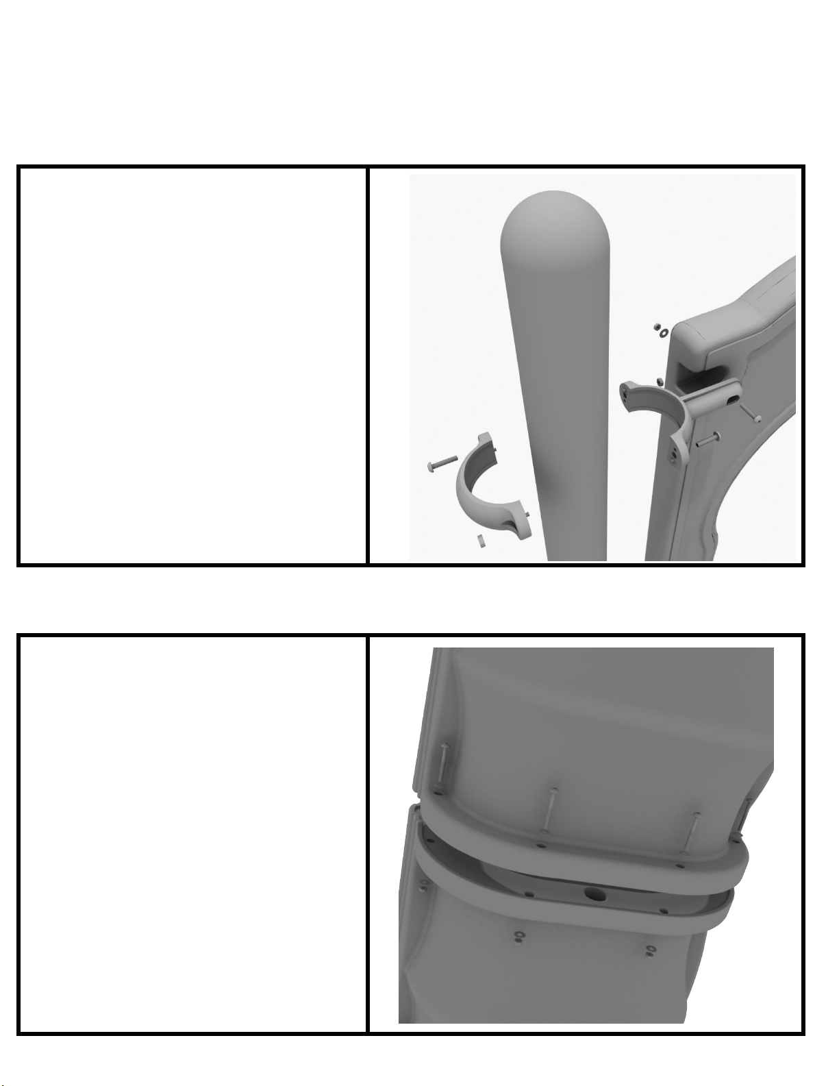
Step 1
Take one (1) 3.5-inch flat clamp, and
loosely attach it around a post using
the bolts and nuts provided in the
clamp hardware bag. Repeat this
process on the other post. Then, use
one (1) M8*40 bolt, one (1) M8
washer, and one (1) M8 lock nut to
attach each side of the slide hood to
each clamp. Leave bolts loose until
slide is in place.
Step 2
Using the hardware pre-attached to
the slide, connect the two sections of
the slide together.
Page 12
Step 3
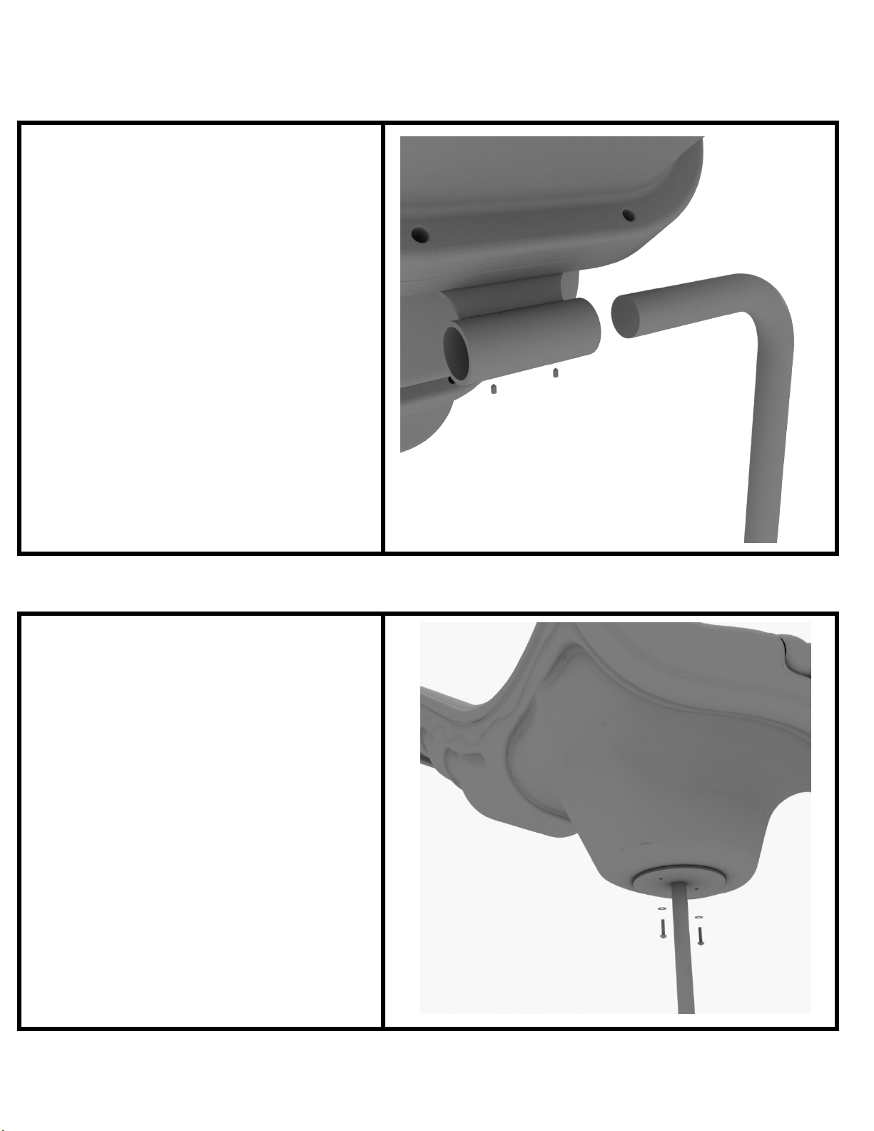
See general installation guide footing
information regarding installation of
the middle supports, and slide end
mount. Insert the middle support
into the designated slot under the
slide, and tighten the set screws
using the provided allen wrench.
Repeat this process for the other
slide support post.
Step 4
Using two (2) M8*20, two (M8)
spring gaskets, and two (2) M8
washers, attach the slide to the slide
end mount.
Page 13
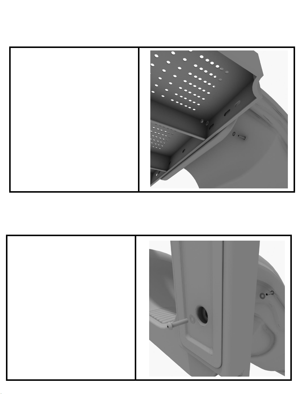
Step 5
Using one (1) M10*45 bolt, two (2)
M10 washers, and two (2) M10 lock
nuts, attach one side of the slide to
the deck. Repeat the process for the
other side of the slide.
Step 6
Using one (1) M8*45 bolt, one (1) M8
washer, one (1) M12 washer, and one
(1) M12 Inner hex spiral nut, attac
he slide to one side of the slide hood.
t
Repeat this process for the other side
of the slide. Make sure all bolts are
properly tightened.
h
Page 14
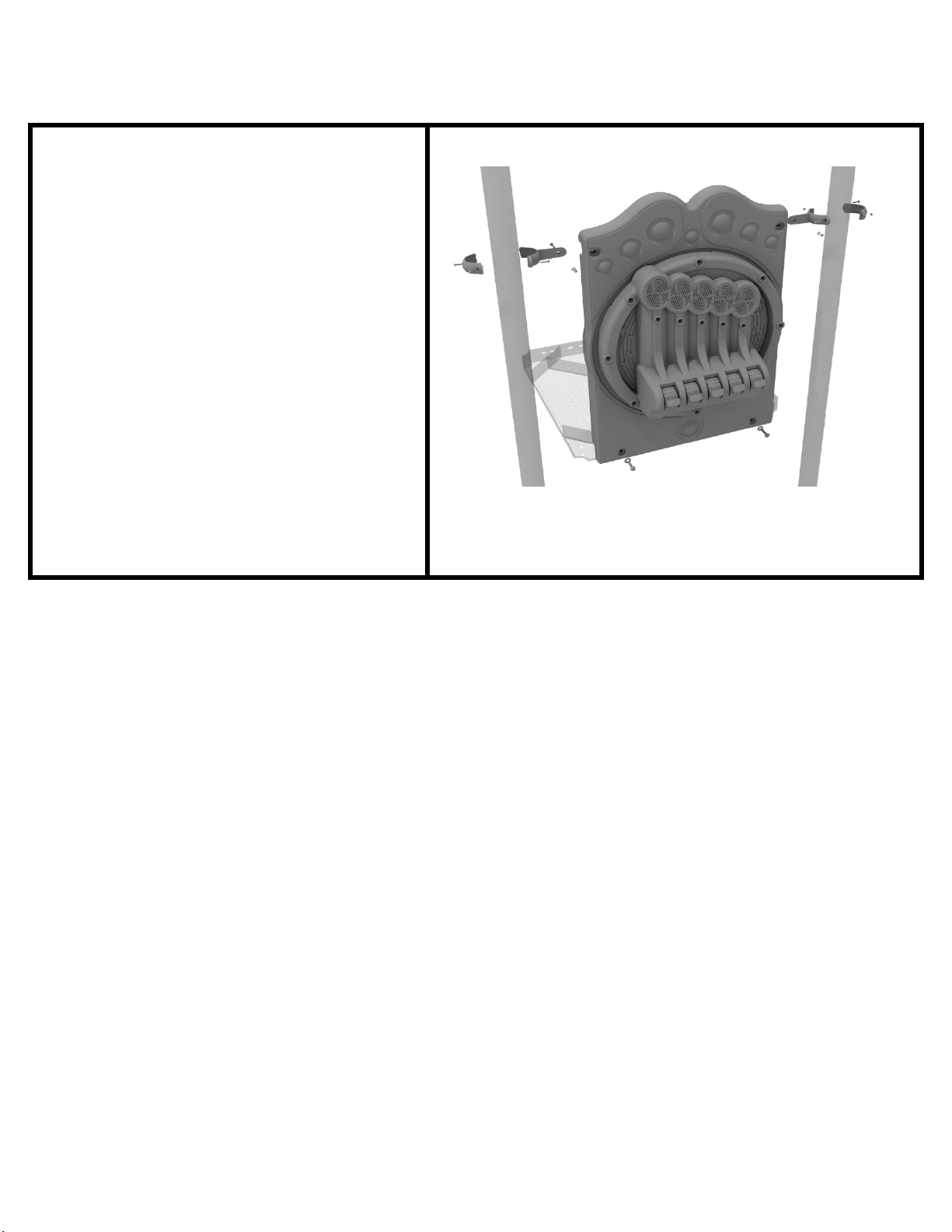
3.5-inch Chime Panel Installation
Connect the bottom of the panel to
the deck using two (2) M10*50 bolts,
four (4) M10 washers, and two (2)
M10 lock nuts. Then attach the top
of the panel to the posts using two
(2) flat clamps.
STEP: 1
10859 Washington St. Suite
200, Indianapolis, IN
1-800-667-0097
Page 1 of 1 (3.5-inch Tic Tac Toe Panel Installation)
Created By: Aaron Price
Date: 04/04/2018
Page 15
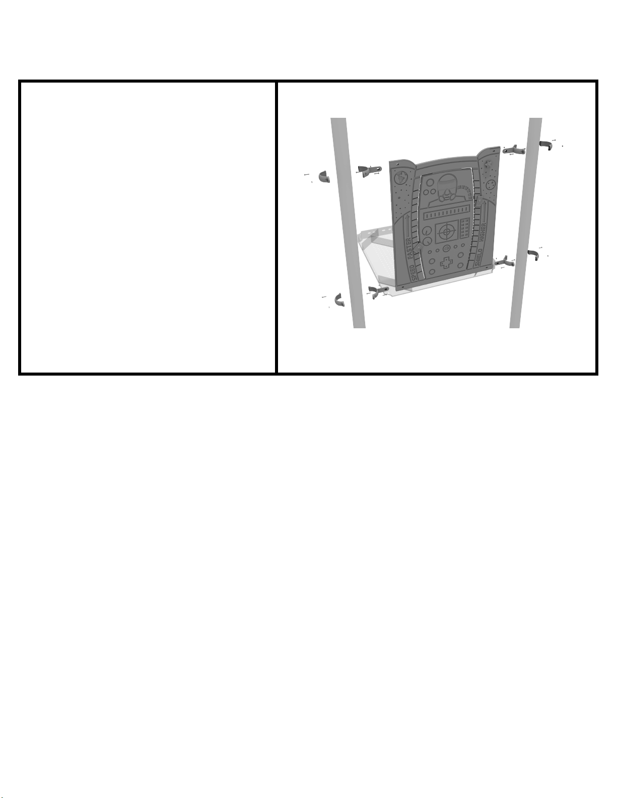
3.5-Inch Space Planet Power Panel Installation
STEP: 1
Connect the bottom of the panel to
deck using two (4) M10*50 bolts,
the
four (8) M10 washers, and two (4)
M10 lock nuts. Then attach the top
of the panel to the posts using two
(4) flat clamps.
10859 Washington St. Suite
200, Indianapolis, IN
1-800-667-0097
Page 1 of 1 ( 3.5-Inch Space Planet Power Panel Installation )
Created By: Jordan B
Date: 05/19/2022
Page 16

Single Drum Installation
Detach half of the tube clamps
connected to the Single Drum, and
re-attach the clamps around the
support post, as shown in the image.
Recommended install height is 20 to
36 inches above surfacing depending
on age range.
We recommend using Thread-
locking fluid on bolts connecting
Single Drum to clamp to prevent
hardware from loosening over time.
(Thread-locker not supplied)
layground Drive Created By: Aaron Price
1 P
Greenfield, IN 46140 Date: 04/18/2018
1-800-667-0097
Page 1 of 1 (Single Drum Installation)
 Loading...