

Page 1
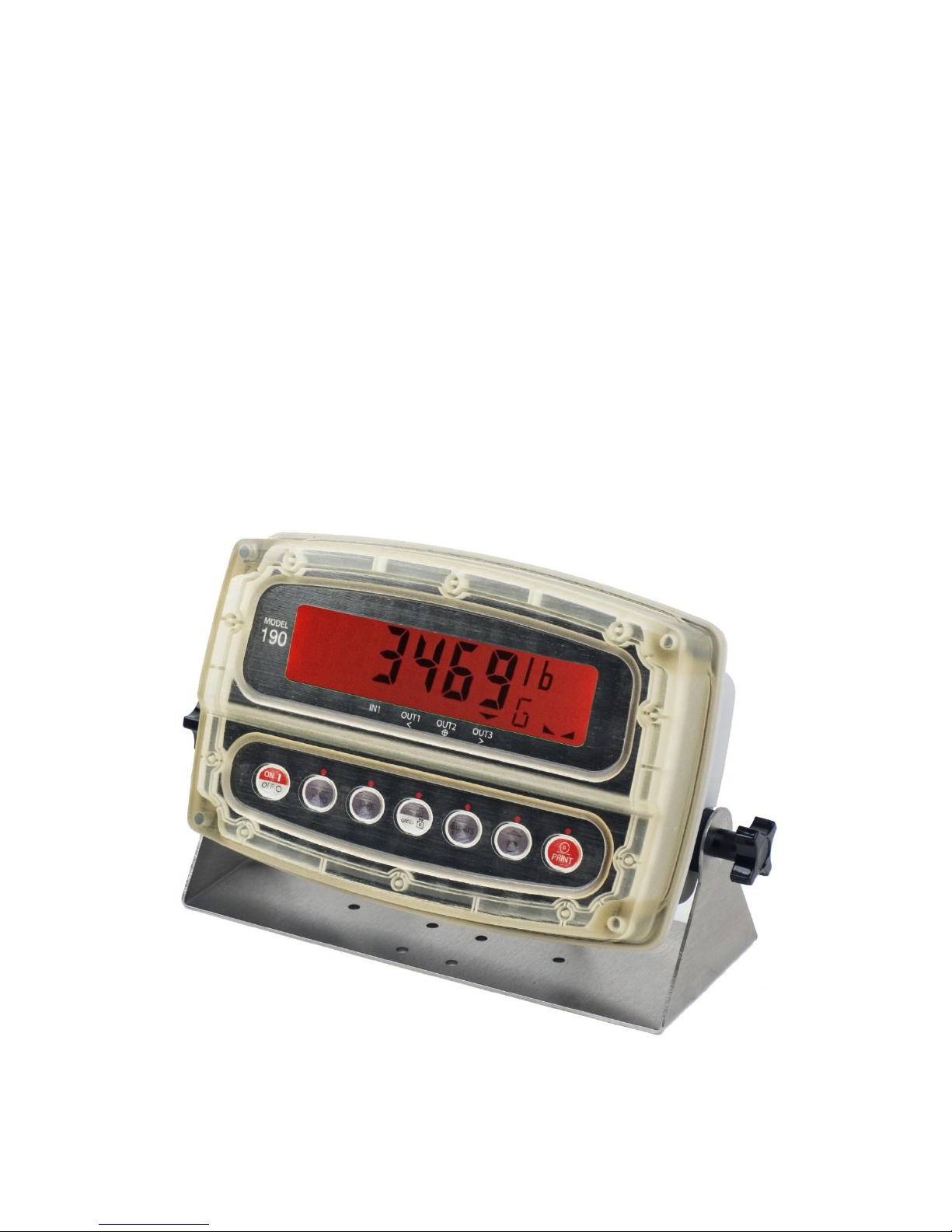
JAC190 Installation & Technical
Page I
NUWEIGH
Model JAC190 Indicator
Installation, Technical
and Operation Manual
8400-M022-O1 Rev A 02/11
Page 2
JAC190 Installation & Technical
Page II
PRECAUTIONS
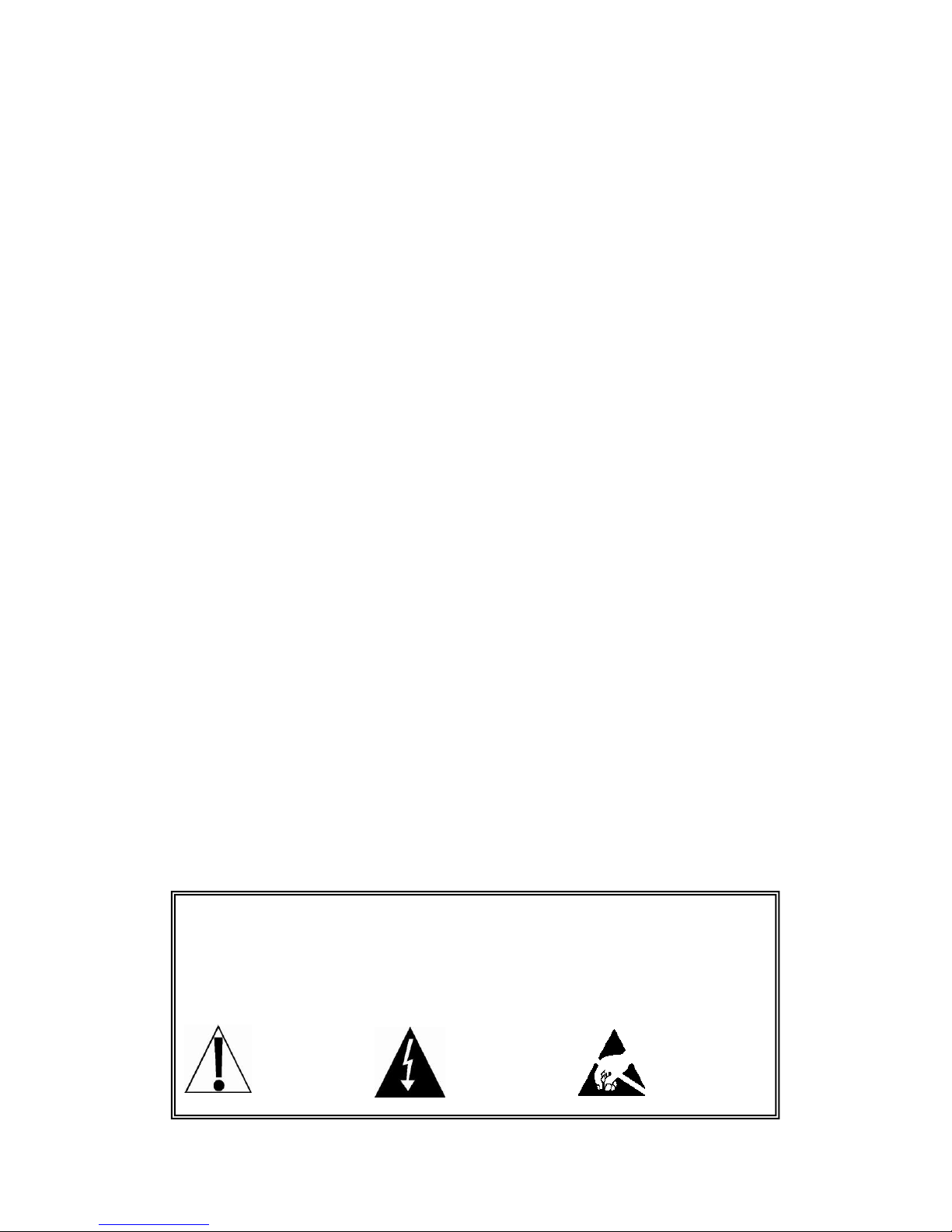
Before using this indicator, read this manual and pay special
attention to all "WARNING" symbols:
ELECTRICAL STATIC
IMPORTANT WARNING SENSITIVE
Introduction
Thank you for selecting and purchasing the Nuweigh Model JAC190 Weight Indicator.
The Model JAC190 indicator was built with quality and reliability at our factory in Webb
City, Missouri and incorporates the latest in digital technology and innovative features
for the weighing industry. Configuration and upgrades can easily be performed in the
field, while still maintaining the rigid control the most demanding installations require.
This flexibility insures the Model JAC190 will be able to meet your weight indicating
needs for years to come.
The purpose of this manual is to provide you with a guide through installation, setup and
operation of your new Model JAC190 Weight Indicator. Please read it thoroughly before
attempting to install your indicator and keep it handy for future reference
Copyright
All rights reserved. Reproduction or use, without expressed written permission, of
editorial or pictorial content, in any manner, is prohibited. No patent liability is assumed
with respect to the use of the information contained herein.
Disclaimer
While every precaution has been taken in the preparation of this manual, the Seller
assumes no responsibility for errors or omissions. Neither is any liability assumed for
damages resulting from use of the information contained herein. All instructions and
diagrams have been checked for accuracy and ease of application; however, success
and safety in working with tools depend to a great extent upon the individual accuracy,
skill and caution. For this reason the Seller is not able to guarantee the result of any
procedure contained herein. Nor can they assume responsibility for any damage to
property or injury to persons occasioned from the procedures. Persons engaging the
procedures do so entirely at their own risk.
8400-M022-O1 Rev A 02/11
Page 3

JAC190 Installation & Technical
Page III
FCC Compliance Statement
Warning! This equipment generates uses and can radiate radio frequency and if not
installed and used in accordance with the instruction manual, may cause interference
to radio communications. It has been tested and found to comply with the limits for a
Class A computing device pursuant to Subpart J of Part 15 of FCC rules, which are
designed to provide reasonable protection against such interference when operated in
a commercial environment. Operation of this equipment in a residential area may
cause interference in which case the user will be responsible to take whatever
measures necessary to correct the interference.
You may find the booklet “How to Identify and Resolve Radio TV Interference
Problems” prepared by the Federal Communications Commission helpful. It is
available from the U.S. Government Printing Office, Washington, D.C. 20402. Stock
No. 001-000-00315-4.
Proper Disposal
When this device reaches the end of its useful life, it must be properly disposed of. It
must not be disposed of as unsorted municipal waste. Within the European Union, this
device should be returned to the distributor from where it was purchased for proper
disposal. This is in accordance with EU Directive 2002/96/EC. Within North America,
the device should be disposed of in accordance with the local laws regarding the
disposal of waste electrical and electronic equipment.
It is everyone’s responsibility to help maintain the environment and to
reduce the effects of hazardous substances contained in electrical and
electronic equipment on human health. Please do your part by making
certain that this device is properly disposed of. The symbol shown to
the right indicates that this device must not be disposed of in unsorted
municipal waste programs.
8400-M022-O1 Rev A 02/11
Page 4

JAC190 Installation & Technical
Page IV
TABLE OF CONTENTS
PRECAUTIONS .............................................................................................................. II
1. SPECIFICATIONS ...................................................................................................... 1
1.1 Standard Features ................................................................................................. 2
1.2 Optional Features ................................................................ ................................ .. 2
2. PRECAUTIONS .......................................................................................................... 3
2.1 Static Electricity ..................................................................................................... 3
2.2 Batteries ................................................................................................................ 3
3. INSTALLATION ........................................................................................................... 4
3.1 Site Preparation Requirements .............................................................................. 4
3.1.1 Environmental ..................................................................................................... 4
3.1.2 Electrical Power ................................ ................................ .................................. 5
3.1.3 Electrical Noise Interference ............................................................................... 6
3.1.4 Transient Suppression ........................................................................................ 6
3.2 Mounting ................................................................................................................ 7
3.3 Load Cell Connections ........................................................................................... 8
3.4 Load Cell Connections with Over 30 Feet of Cable ............................................. 10
3.5 Sense and Dead Load Jumpers .......................................................................... 10
3.6 Serial and I/O Cable Installation .......................................................................... 11
3.7 Re-Installing the Front Panel ............................................................................... 12
4. INDICATOR SETUP .................................................................................................. 13
4.1 Calibration Inhibit Jumper .................................................................................... 13
4.2 Calibration Data Entry .......................................................................................... 15
4.3 Accessing Setup ................................................................................................ .. 16
4.4 Settings ................................................................................................................ 17
4.5 Analog to Digital Filtering ..................................................................................... 23
4.5.1 Filter Setting Recommendations ....................................................................... 25
4.6 Calibration ........................................................................................................... 26
4.6.1 Dual-Point with Zero (First Zero) Calibration .................................................... 27
4.6.2 Dual-Point without Zero (False Zero) Calibration .............................................. 29
4.6.3 Single-Point for Span Only (Last Zero) Calibration ........................................... 30
4.6.4 Single-Point for Zero Only (Only Zero) Calibration ........................................... 31
4.6.5 Multi-Point Calibration ....................................................................................... 32
8400-M022-O1 Rev A 02/11
Page 5

JAC190 Installation & Technical
Page V
4.6.6 Calibration “C” Numbers ................................................................................... 35
4.7 Set Gravity Constant ............................................................................................ 36
4.8 Serial Input/Output ............................................................................................... 37
4.9 Print Tab Settings ................................................................ ................................ 40
4.10 Fine Span Adjustment ....................................................................................... 44
4.11 Display High Resolution Weight ........................................................................ 45
4.12 Key Lockout Feature.......................................................................................... 46
4.13 Options Setup .................................................................................................... 49
4.14 Function Setup .................................................................................................. 52
4.15 Display Backlight Color Setup ........................................................................... 55
5. CALIBRATION SEAL ................................................................................................ 57
5.1 Installing the Calibration Seal .............................................................................. 57
6. KEYPAD .................................................................................................................... 58
6.1 Standard Key Functions ...................................................................................... 58
6.2 Fn/ Key Functions ............................................................................................ 62
6.3 Fn/ Key Combination Features ......................................................................... 63
7. ANNUNICATORS ...................................................................................................... 64
7.1 Annunicators ........................................................................................................ 64
7.2 Battery Status ...................................................................................................... 67
8. INDICATOR SETUP REVIEW................................................................................... 68
8.1 Accessing Setup Review ..................................................................................... 68
9. OPERATION ............................................................................................................. 70
9.1 Ticket Format Selection ....................................................................................... 70
9.2 Preset Weight Comparators ................................................................................ 71
9.3 Hold Function ...................................................................................................... 73
9.4 Count Function .................................................................................................... 74
9.5 Time and Date Functions ..................................................................................... 76
9.6 Peak Hold Function ............................................................................................. 77
9.7 Checkweigher ...................................................................................................... 78
9.8 Live Weight Function ........................................................................................... 79
9.9 Accumulated Weight Function ............................................................................. 81
10. ERROR MESSAGES .............................................................................................. 83
10.1 Before You Call Service ..................................................................................... 83
10.2 Error Codes ....................................................................................................... 85
8400-M022-O1 Rev A 02/11
Page 6

JAC190 Installation & Technical
Page VI
11. EVENT COUNTERS ............................................................................................... 87
11.1 Event Counters ................................................................................................ .. 87
11.2 Accessing the Event Counters ........................................................................... 87
12. TEST MODE/ DIAGNOSTICS ................................................................................. 89
12.1 Test Mode/Diagnostics Features ................................................................ ....... 89
12.2 Accessing Test Mode/Diagnostics ..................................................................... 89
13. PARTS IDENTIFICATION ....................................................................................... 90
13.1 Front Sub Assembly .......................................................................................... 90
13.2 Rear Sub Assembly ........................................................................................... 91
13.3 Power Supply Sub Assembly ............................................................................. 92
13.4 AC Wiring Detail ................................................................................................ 93
8400-M022-O1 Rev A 02/11
Page 7

Page 1
1. SPECIFICATIONS
Power Requirements:
100 to 240 VAC (50/60 Hz) at 0.4A Max.
Enclosure Type:
Thermoplastic IP69K wall or desk-mount
Enclosure Size:
9.4” W x 6.4” H x 3.7" D
(239mm W x 163mm H x 93mm D)
Operating Environment:
Temperature: 14 to 104 ºF (-10 to +40 ºC)
Humidity: 90% non-condensing (maximum)
Display:
Six digit, seven segment, 1.0" high Backlit LCD
Transducer Excitation:
5.15 VDC
Signal Input Range:
0.5 mV min. to 40 mV max. (with dead load boost)
Number of Load Cells:
6 each, 350 OHM minimum resistance
Load Cell Cable Length:
1500 feet maximum.
30 feet maximum without sense lines
Consult factory for other requirements
Division Value:
1, 2, or 5 x 10, 1, 0.1, 0.01, 0.001 commercial
0 to 99, non-commercial
Sensitivity:
NON-COMMERCIAL
NTEP
CANADA
0.15 uV/e
0.5uV/e (Class III/IIIL)
0.5uV/e (Class III/IIIHD)
Scale Divisions:
NON-COMMERCIAL
NTEP
CANADA
100 to 240,000
100 to 10,000 (Class III/IIIL)
100 to 10,000 (Class III/IIIHD)
Internal Resolution:
1 part in 16,777,216
Tare Capacity:
Scale Capacity
Sample Rate:
1 to 100 samples per second, selectable
Auto Zero Range:
0.5 or 1 through 9 divisions
Weighing Units:
Pounds, Ounces, Kilograms, Grams
Keypad:
Color Coded Capacitive Touch type, 7 keys
Standard I/O:
(1) bi-directional RS232
JAC190 Installation & Technical
8400-M022-O1 Rev A 02/11
Page 8

JAC190 Installation & Technical
Page 2
1.1 Standard Features
Push button tare function
Gross, tare, net conversion
Selectable key lockout
Hi-Resolution mode
Adjustable filtering
Gross and Net accumulators
Single serial port
Remote input line for Zero, Tare, Gross and Print (1000
feet maximum)
Programmable print format using Visual Print or nControl
(1 Visual Ticket available)
SMA level 2 compliant serial communications (For more
information see http://www.scalemanufacturers.org)
Field re-programmable via PC interconnection
Test feature (performs display and internal tests)
Auto Shutoff and Sleep modes
Battery operation (Requires additional hardware and
includes additional documentation)
1.2 Optional Features
Additional Serial Port*, Special Filtering, and Column Mounting
*This feature requires additional hardware and includes additional
documentation.
8400-M022-O1 Rev A 02/11
Page 9
Page 3
2. PRECAUTIONS
2.1 Static Electricity
JAC190 Installation & Technical
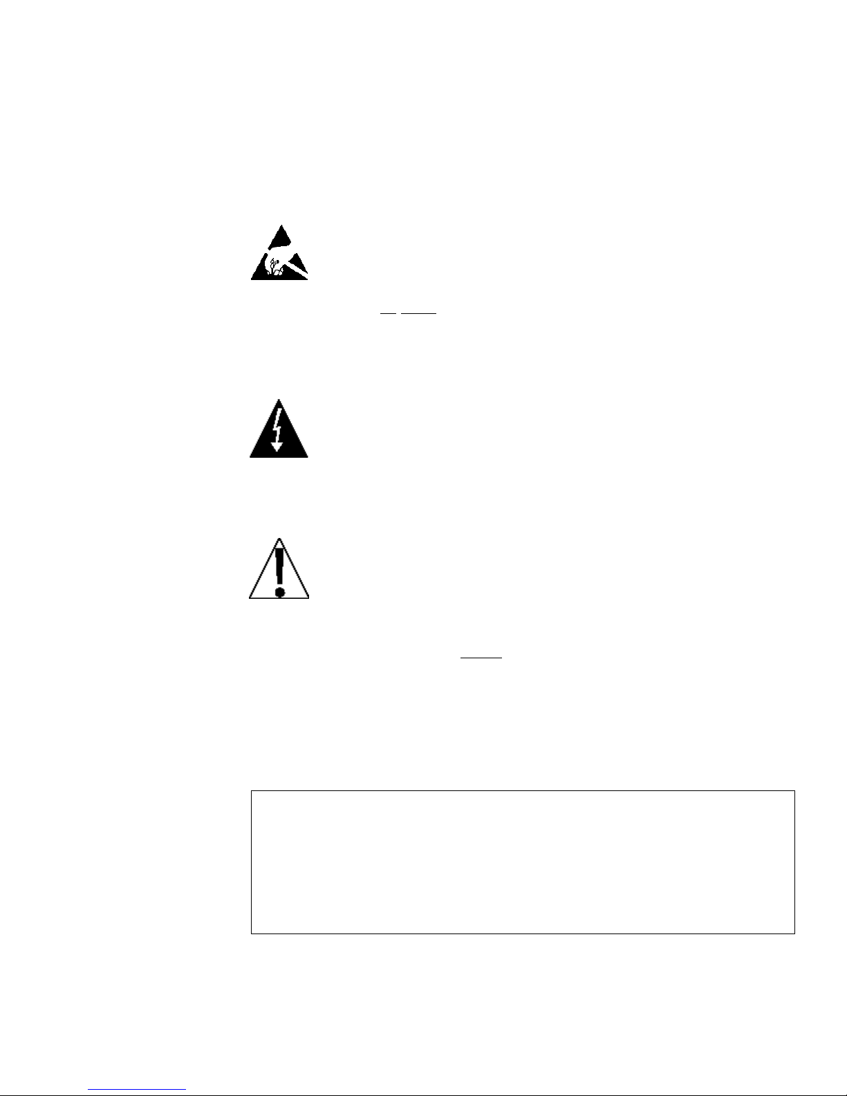
CAUTION! This device contains static sensitive circuit cards
and components. Improper handling of these devices or
printed circuit cards can result in damage to or destruction of
the component or card. Such actual and/or consequential
damage IS NOT covered under warranty and is the
responsibility of the device owner. Electronic components
must be handled only by qualified electronic technicians who
follow the guidelines listed below.
ATTENTION! ALWAYS use a properly grounded wrist strap
when handling, removing or installing electronic circuit cards or
components. Make certain that the wrist strap ground lead is
securely attached to an adequate ground. If you are uncertain
of the quality of the ground, you should consult a licensed
electrician.
2.2 Batteries
ALWAYS handle printed circuit card assemblies by the
outermost edges.
NEVER touch the components, component leads or
connectors.
ALWAYS observe warning labels on static protective bags
and packaging and never remove the card or component from
the packaging until ready for use.
ALWAYS store and transport electronic printed circuit cards
and components in anti-static protective bags or packaging.
CAUTION: RISK OF EXPLOSION IF BATTERY IS REPLACED BY AN
INCORRECT TYPE. DISPOSE OF USED BATTERIES ACCORDING
TO THE INSTRUCTIONS.
ATTENTION: RISQUE D'EXPLOSION SI LA BATTERIES EST
REMPLACE'E PAR UN TYPE INCORRECT. REJETEZ LES
BATTERIES UTILISE'ES SELON LES INSTRUCTIONS.
8400-M022-O1 Rev A 02/11
Page 10
JAC190 Installation & Technical
Page 4
3. INSTALLATION
3.1 Site Preparation Requirements
The Nuweigh Model JAC190 indicator is a precision weight-measuring
instrument. As with any precision instrument, it requires an acceptable
environment to operate at peak performance and reliability. This section
is provided to assist you in obtaining such an environment.
3.1.1 Environmental
The JAC190 indicator meets or exceeds all certification requirements
within a temperature range of 14 to 104 °F (-10 to +40 °C).
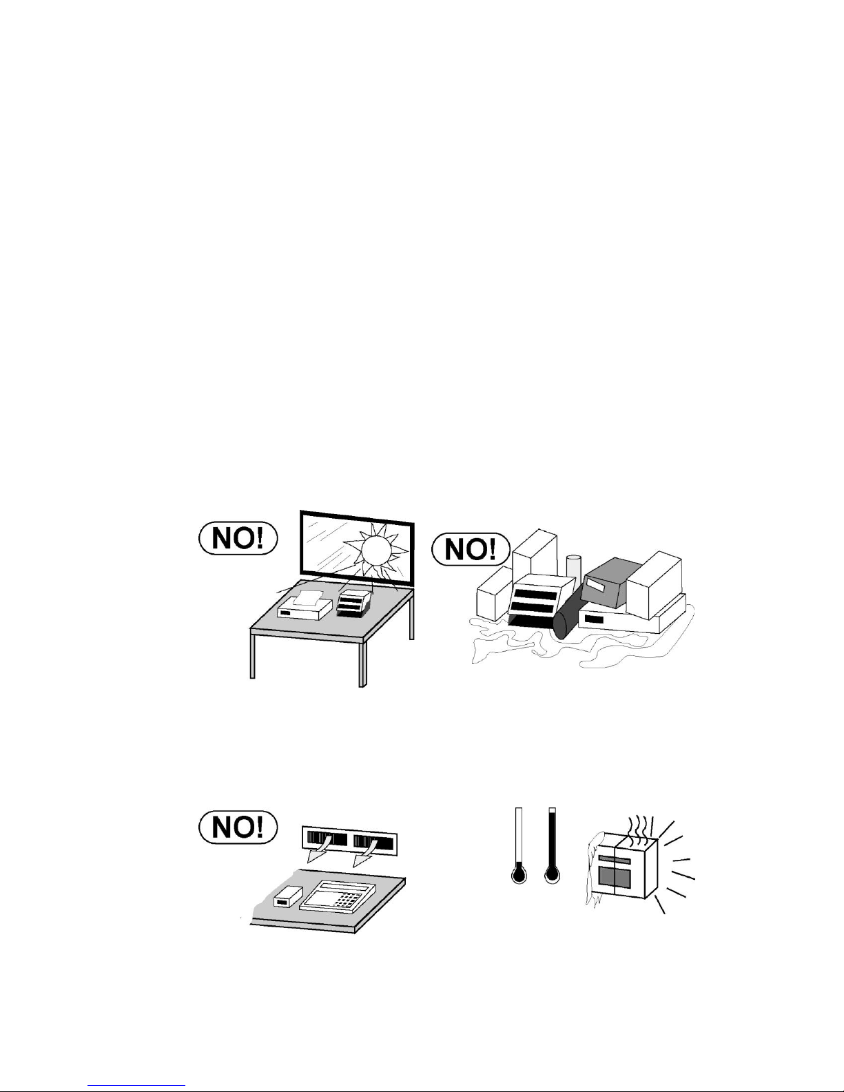
In order to keep cooling requirements to a minimum, the indicator should
be placed out of direct sunlight and to provide adequate air circulation,
keep the area around the indicator clear.
Make certain the indicator is not directly in front of a heating or cooling
vent. Such a location will subject the indicator to sudden temperature
changes, which may result in unstable weight readings.
8400-M022-O1 Rev A 02/11
Page 11
Page 5
Insure that the indicator has good, clean AC power and is properly
grounded. In areas subject to lightning strikes, additional protection
to minimize lightning damage, such as surge suppressors, should
be installed.
3.1.2 Electrical Power
The JAC190 has been designed to operate from 100 to 240 VAC @
0.4A Max. at 50/60 Hz. Note that a special order is not required for
operation at 230/240 VAC.
JAC190 Installation & Technical
CAUTION! - To avoid electrical hazard and
possible damage to the indicator, DO NOT, under
any circumstance, cut, remove, alter, or in any
way bypass the power cord grounding prong.
The socket-outlet supplying power to the indicator should be on
a separate circuit from the distribution panel and dedicated to
the exclusive use of the indicator.
The socket-outlet shall be installed near the equipment and
shall be easily accessible. Note that the power cord on the
JAC190 serves as the power disconnect.
The wiring should conform to national and local electrical codes
and ordinances and should be approved by the local inspector
to assure compliance.
For outdoor operations, the socket-outlet must provide GFCI
(ground fault circuit interrupter) protection.
On installations requiring 230/240 VAC power, it is the
responsibility of the customer to have a qualified electrician
install the proper power cord plug that conforms to national
electrical codes and local codes and ordinances.
8400-M022-O1 Rev A 02/11
Page 12

JAC190 Installation & Technical
Page 6
3.1.3 Electrical Noise Interference
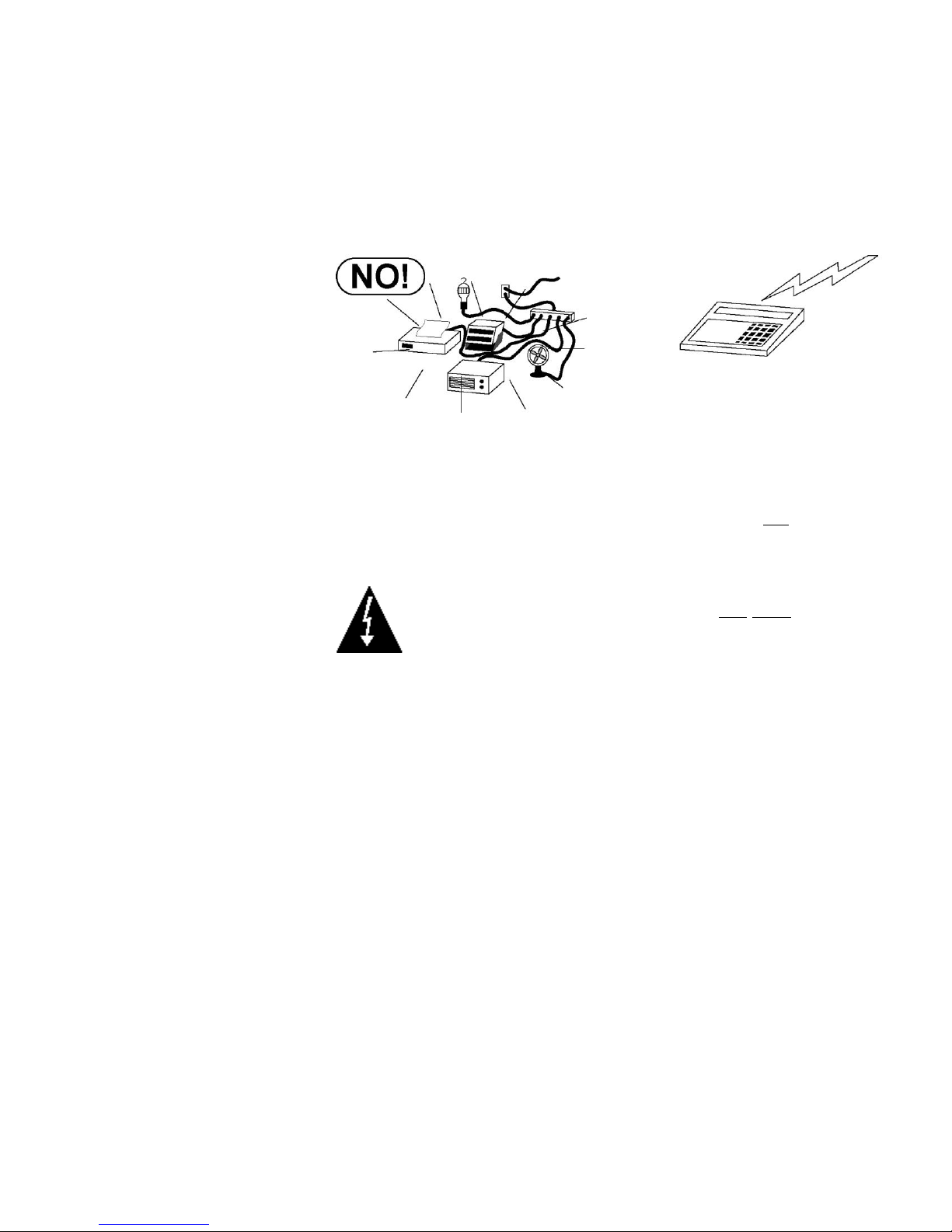
To prevent electrical noise interference, make certain all other wall outlets
for use with air conditioning and heating equipment, lighting or other
equipment with heavily inductive loads, such as welders, motors and
solenoids are on circuits separate from the indicator. Many of these
disturbances originate within the building itself and can seriously affect the
operation of the instrument. These sources of disturbances must be
identified and steps must be taken to prevent possible adverse effects on
the instrument. Examples of available alternatives include isolation
transformers, power regulators, uninterruptible power supplies, or simple
line filters.
3.1.4 Transient Suppression
The following recommendations will help to reduce transients:
Always use shielded cables to connect signal wires to the weight
indicator.
Secure the cables in the cable clips provided inside the indicator.
Connect the cable shield (indicator end only) to a ground point
inside the indicator. Keep wires that extend beyond the shield as
short as possible.
Do not run load cell or signal cables from the weight indicator
along side or parallel to wiring carrying AC power. If unavoidable,
position the load cell and signal cables a minimum of 24" away
from all AC wiring.
Always use arc suppressors across all AC power relay contacts (see
recommendations at www.paktron.com/pdf/Quencharch_QRL.pdf).
Use zero voltage switching relays, optically isolated if possible.
8400-M022-O1 Rev A 02/11
Page 13
Page 7
3.2 Mounting
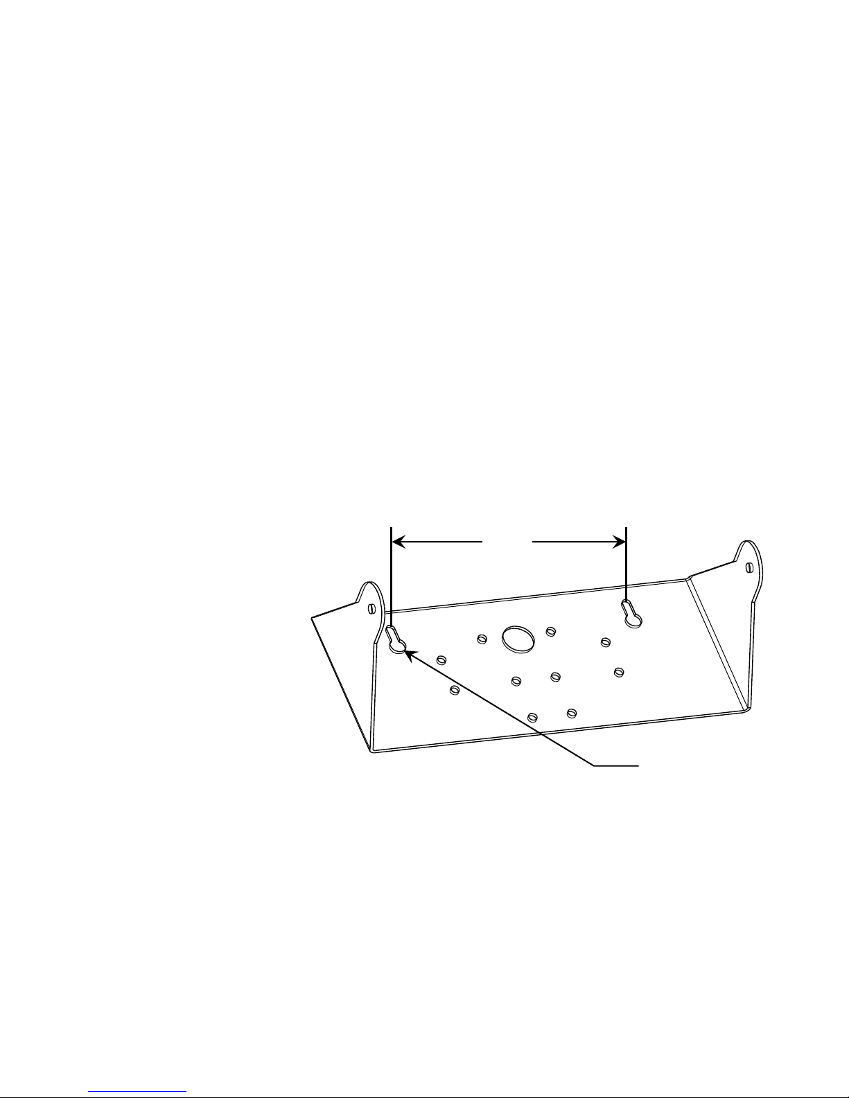
6.00"
Clearance for
#10 size screw
Before beginning installation of your Model JAC190 Indicator, make
certain that it has been received in good condition. Carefully
remove it from the shipping carton and inspect it for any evidence
of damage (such as exterior dents or scratches) that may have
taken place during shipment. Keep the carton and packing material
for return shipment if it should become necessary. It is the
responsibility of the purchaser to file all claims for any damages or
loss incurred during transit.
NOTE! Should your Model JAC190 indicator come already
installed on a scale, the following information describing the
installation of the indicator does not apply.
The Model JAC190 indicator is housed in a Thermoplastic IP69K
wall or desk-mount enclosure. The gimbal may be mounted on a
desktop or other smooth, flat, horizontal surface or may be
mounted on a wall. Refer to Figure No. 1 for a layout of wallmounting bolts.
JAC190 Installation & Technical
Figure No. 1
If wall mounted, make certain the mounting surface is strong
enough to support the indicator. The mounting location should be
where the display is easily viewed while being close enough to
provide the operator easy access to the keypad. Carefully lay out
the mounting hole locations, then drill and install the anchor bolts.
Attach the gimbal to the wall and securely tighten the retaining
bolts.
8400-M022-O1 Rev A 02/11
Page 14
JAC190 Installation & Technical
Page 8
CAUTION! Disconnect any external load cell
power supply before connecting load cells to the
indicator. Failure to do so will result in permanent
damage to the indicator.
AC Power
100-240 VAC
0.4 Amp
Scale
I/O
(Serial, Isolated
Inputs/Outputs)
Figure No. 3
1/4”
3”
3.3 Load Cell Connections
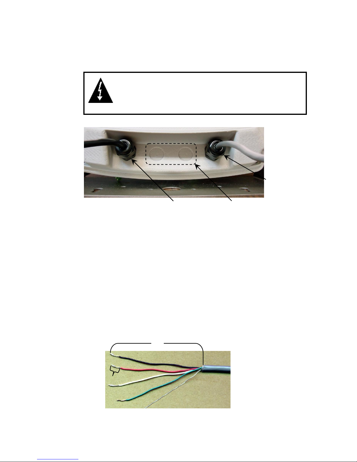
Figure No. 2
3.3.1. Remove the 4 screws securing the front panel to the rear housing.
3.3.2. Referring to Figure No. 2, choose a gland connector for the load cell
cable and loosen it.
3.3.3. Slip the single cable from the load cell or load cell junction box
through the gland connector and into the enclosure.
3.3.4. Referring to Figure No. 3, remove 3 inches of the outer insulation
jacket.
3.3.5. Next, remove 1/4 inch of insulation from each of the six wires and
shield (with sense leads) or four wires and shield (without sense
leads).
8400-M022-O1 Rev A 02/11
Page 15
JAC190 Installation & Technical
Page 9
Load Cell Wiring Table
Board Label
Function
Board Label
Function
+EXC
+ EXCITATION
-SIG
- SIGNAL
+SEN
+ SENSE
-SEN
- SENSE
+SIG
+ SIGNAL
-EXC
- EXCITATION
SHLD
SHIELD (Connect the load cell cable shield wire here).
Insert wire
and tighten
screw.
Load Cell
Shield Wire
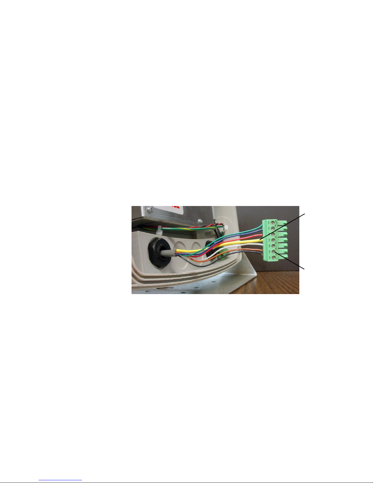
3.3.6. Remove the 7-connector terminal block connector from P5
on the JAC190 main board. Grasp the terminal block
connector and lift straight up away from the board.
3.3.7. Referring to the table below and the labels on the circuit
board for terminal connections, connect each wire to the
terminal block.
3.3.8. To terminate a wire, loosen the screws in the terminal block
and then insert the wire into the terminal opening. Tighten
the screw to secure the wire in place. See Figure No. 4.
Figure No. 4
3.3.9. Repeat the procedure until all wires are in place.
3.3.10. After all terminations have been made, remove the excess
cable from the enclosure.
8400-M022-O1 Rev A 02/11
Page 16
JAC190 Installation & Technical
Page 10
3.4 Load Cell Connections with Over 30 Feet of Cable
For installations with over 30 feet of cable between the indicator and the
load cells, sense wires should be used. The sense wires must be
connected between the +SENS, -SENS terminals on the indicator and the
+EXCITATION, -EXCITATION wires of the load cells or the +SENS, SENS terminals of the load cell trim board or the section seal trim board.
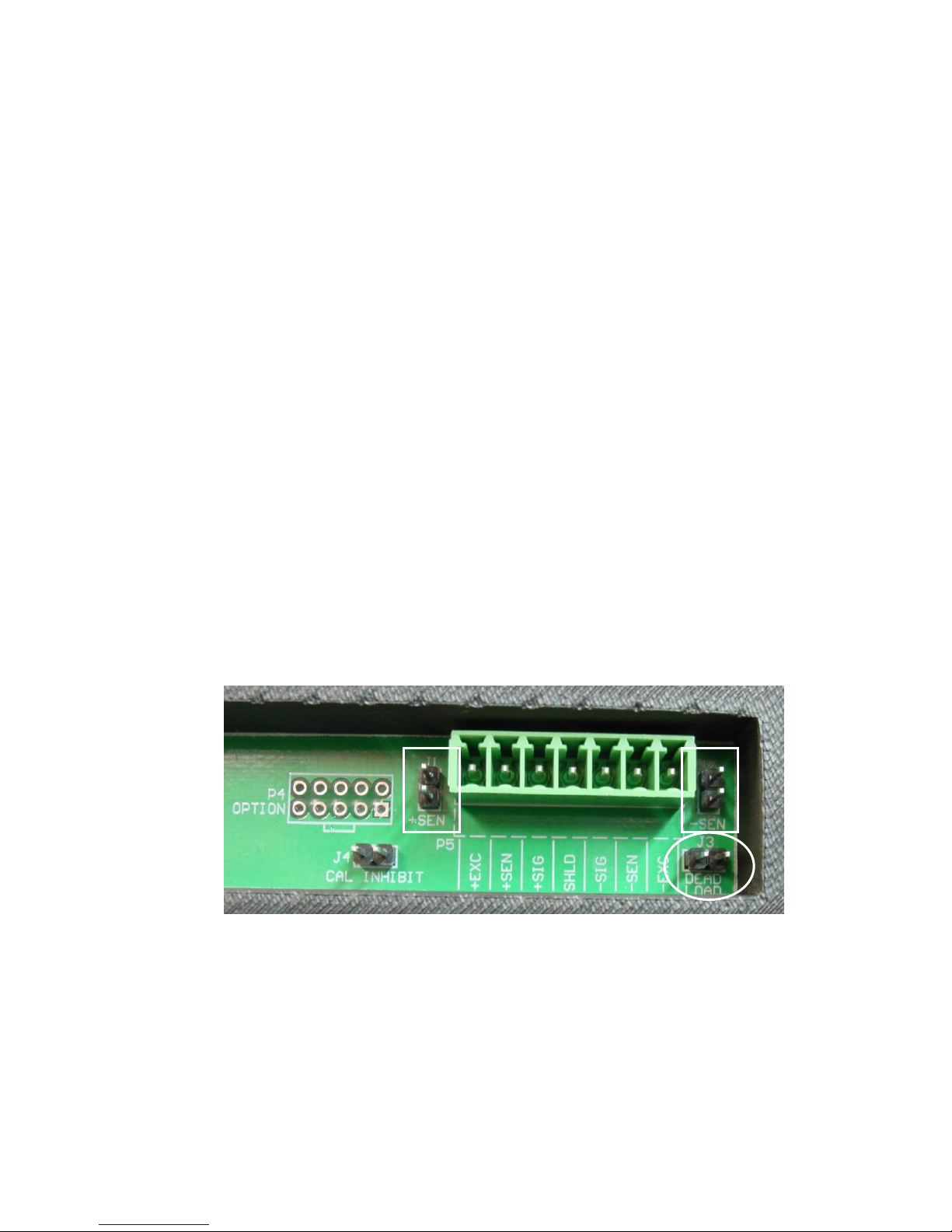
3.5 Sense and Dead Load Jumpers
J1 (+SEN) and J2 (-SEN) – Sense Jumpers
If the sense leads are NOT used, you must install the +SEN and -SEN
jumpers at J1 and J2 (near the P5 terminal block). These jumpers
connect the sense leads to the excitation leads. If sense leads ARE used
(as in motor truck scales or installations with over 30 feet between the
indicator and load cells), these jumpers should be open (on one pin only)
or removed.
J3 (DEAD LOAD) – Dead Load Boost Jumper
For scales with very low dead loads (less than 10% of the combined load
cell capacity), connect the DEAD LOAD (dead load boost) jumper J3 (near
the P5 terminal block).
Figure No. 5
8400-M022-O1 Rev A 02/11
Page 17
Page 11
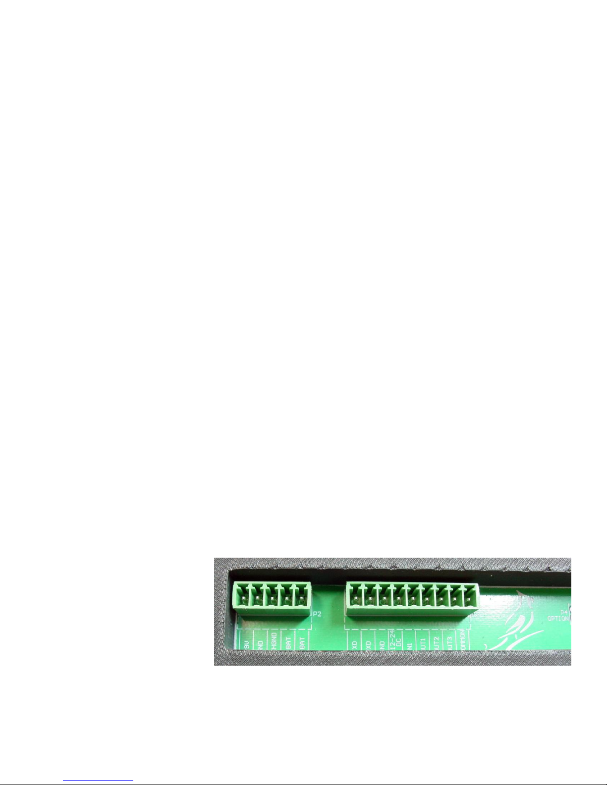
3.6 Serial and I/O Cable Installation
SERIAL INTERFACE
INPUT/OUTPUTS
Terminal
Function
Terminal
Function
1
TXD
5
IN1
2
RXD
6
OUT1
3
GND
7
OUT2
4
+12-24 DC
8
OUT3
9
COMMON
P3
P2
3.6.1. Remove the 4 screws securing the front panel to the rear
housing and then loosen a gland connector for the serial
cable. Refer to Figure No. 2 for an illustration of the
connector layout.
3.6.2. Slip the serial cable through the gland connector and into
the enclosure.
3.6.3. Remove 3" of the outer insulation jacket then remove 1/4"
of insulation from each of the wires (refer to Figure No. 3).
3.6.4. Remove the 9-connector terminal block connector from P3
on the 190 main board. Grasp the terminal block
connector and lift straight up away from the board.
3.6.5. Referring to the table below and the labels on the circuit
board for terminal connections, connect each wire to the
terminal block.
JAC190 Installation & Technical
3.6.6. To terminate a wire, loosen the screws in the terminal
block and then insert the wire into the terminal opening.
Tighten the screw to secure the wire in place.
3.6.7. Repeat the procedure until all wires are in place.
3.6.8. After all terminations have been made, remove the excess
cable from the enclosure.
8400-M022-O1 Rev A 02/11
Figure No. 6
Page 18

JAC190 Installation & Technical
Page 12
3.7 Re-Installing the Front Panel
3.7.1. After all terminations have been made, remove the excess cable
from the indicator enclosure and securely tighten each of the
cable gland connectors.
3.7.2. Use a wrench to insure the gland connectors are tight (to maintain
a water-tight seal) but do not over-tighten them.
3.7.3. Make certain no cables or wires are exposed between the rear
housing and front panel and then place the front panel onto the
rear housing.
3.7.4. Secure with the 4 screws removed earlier.
8400-M022-O1 Rev A 02/11
Page 19
Page 13
4. INDICATOR SETUP
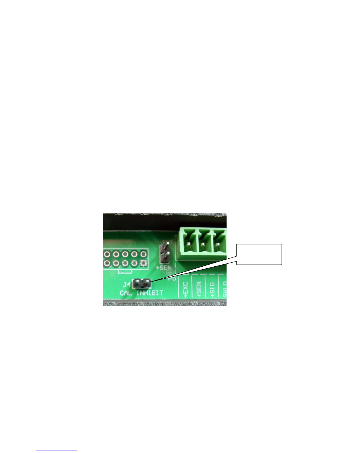
CAL Inhibit
Jumper J4
4.1 Calibration Inhibit Jumper
Your Model JAC190 indicator has been thoroughly tested and calibrated
before being shipped to you. If you received the indicator attached to a
scale, calibration is not necessary. If the indicator is being connected to
a scale for the first time or recalibration is necessary for other reasons,
proceed as indicated.
Calibration and Setup of the indicator is accomplished entirely by the
keypad. However, it may require changing the position of the calibration
inhibit jumper depending on the method of sealing required by your local
metrology laws.
The calibration inhibit jumper (J4) is located on the main printed
circuit board and can only be accessed by removing the front panel
of the indicator.
JAC190 Installation & Technical
Figure No. 7
8400-M022-O1 Rev A 02/11
Page 20

JAC190 Installation & Technical
Page 14
USA
Domestic or International
LFt
Legal For Trade
Unit1
Weighing Units 1 (Primary Units)
Int
Interval Setting
dPP
Decimal Point Precision
CAP
Capacity
Unit2
Weighing Units 2 (Secondary Units)
trA
Zero Tracking Range
trL
4% Zero Limit
PU0
Power Up Zero
dFLt
Digital Filter Number
F
Filter Level Amount
B
Filter Break Range
Sr
Sample Rate
UnS
Motion Range
SC
Stable Count
IMPORTANT! The following setup parameters CAN NOT
be changed with the calibration inhibit jumper (J4)
installed:
8400-M022-O1 Rev A 02/11
Page 21
Page 15
4.2 Calibration Data Entry
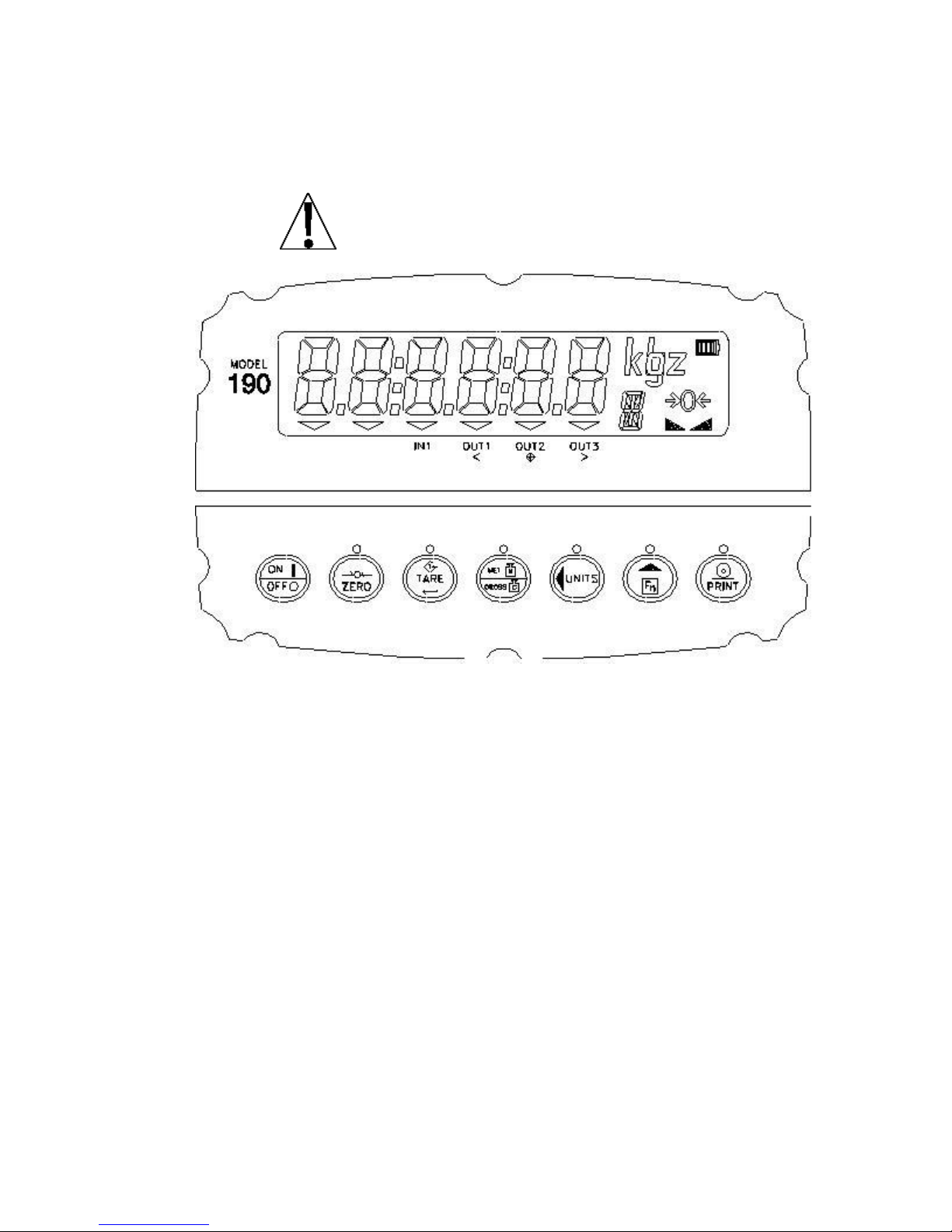
The Model JAC190 uses a capacitive touch keypad that
requires a “finger touch” to function. The keypad will not
operate with other items such as pen, pencil or tools.
JAC190 Installation & Technical
Figure No. 8
During the indicator setup and calibration process it will be necessary to
enter operational parameters via the JAC190 keypad.
Pressing the TARE key will cause the data entered or displayed
to be retained and the JAC190 to advance to the next prompt.
The functions of numeric keys are replaced by using the UNITS/
and the Fn/ keys.
The cursor location is identified by the blinking character and can
be advanced to the left to the next position by pressing the
UNITS/ key.
Pressing the Fn/ key will change the blinking character to the next
value or setting. Continue to press this key to "toggle" between the
different available values or settings for the setup parameter.
Pressing the Fn/ key when a setup parameter (not a parameter
value or setting) is displayed, will "backup" to the previous
parameter prompt.
8400-M022-O1 Rev A 02/11
Page 22

JAC190 Installation & Technical
Page 16
SEtUP
See Note
Below
Setup Mode (starts at USA= prompt)
A-d
A-d?
Analog to Digital Filtering (starts at dFLt= prompt)
CAL
CAL?
Calibration (starts at CAL1= prompt)
SetgC
SetgC?
Set Gravity Constant (starts at CALgC= prompt)
Sio
Sio?
Serial Input/Output (starts at bAUd= prompt)
Print
Print?
Print Tab Settings (starts at Port= prompt)
F SPAn
FSPAn?
Fine Span Adjustment
Hi rES
HirES?
Display High Resolution Weight
LoCoUt
LCoUt?
Key Lockout Feature Setup
option
Opt?
Configuration for Indicator Option Boards
fUnC
fUnC?
Function Setup
CoLors
CoLor?
Display Colors Setup
4.3 Accessing Setup
4.3.1. With the JAC190 ON, press the Fn/ and UNITS/ key
simultaneously
4.3.2. Hold both keys until the display changes to SetUP.
4.3.3. Release the keys to begin setup.
4.3.4. Press the UNITS/ key to step to the beginning point of each setup
section.
4.3.5 If you press the TARE key at the SetUP prompt, you may proceed
through to the next section (up to and including Colors) by pressing
the TARE key.
4.3.6 To exit setup, press the Fn/ key with any of the menu selections
displayed.
NOTE! With the exception of the SEtUP prompt, the prompts
displayed for each section are different if you push the UNITS/ key
to step through the prompts instead of pressing the TARE key to
proceed through the section. For example, if you press the UNITS/
key with the SEtUP displayed, the next prompt displayed will be A-d.
If you step through the setup prompts by pressing the TARE key,
the next prompt displayed will be A-d?. In addition, at a prompt with
the ? displayed, you must press the TARE key again to proceed
with that section. To skip the section and advance you to the next
menu selection, press the TARE key twice.
8400-M022-O1 Rev A 02/11
Page 23

Page 17
4.4 Settings
Yes (Domestic)
no (International)
trL= (4% Zero Range) = no
trL=(4% Zero Range) = yes
CAP (Capacity) = + 4% to OC
CAP (Capacity) = + 9 grads to OC
Date Format = MM/DD/YY
Date Format = DD/MM/YY
Yes = Interval Settings (Int=)
allowed are: 1, 2, 5, 10, 20, 50
no = Interval Setting (Int=) is
selectable from 1 to 99.
When both LFt=yes and USA=yes, the followings results occur:
Scale must have between 100 and 10,000 divisions
Inhibit serial data during input
trA= (Zero Tracking Range) = 0.5 or 0 to 3
trL= (4% Zero Range) = no
CAP (Capacity) = + 4% to OC
When LFt=yes and USA=no, the followings results occur:
UnS= (Motion Range) = 1
trL= (4% Zero Range) = yes
CAP (Capacity) = + 9 grads to OC
SETUP
USA= (Domestic or International)
With SEtUP displayed, press the TARE key. The display will change
to USA=. Press the TARE key to show the current setting. If the
setting displayed is acceptable, press the TARE key again to save it.
Otherwise, use the Fn/ key to toggle to a new setting and then press
the TARE key to save it.
JAC190 Installation & Technical
IMPORTANT! Calibration and configuration parameters are not
stored in the non-volatile memory until setup is left. If power is
lost while in setup mode, any changes made will be lost and the
indicator will revert to the previous configuration.
LFt= (Legal For Trade)
Press the TARE key to show the current setting. If the setting
displayed is acceptable, press the TARE key again to save it.
Otherwise, use the Fn/ key to toggle to a new setting and then press
the TARE key to save it.
8400-M022-O1 Rev A 02/11
Page 24

JAC190 Installation & Technical
Page 18
1 = lb (pounds)
2 = kg (kilograms)
3 = oz (ounces)
4 = g (grams)
0 = XXXXXX
1= XXXXX.X
2 = XXXX.XX
3 = XXX.XXX
Unit1= (Weighing Unit 1)
Press the TARE key to show the current setting. If the setting
displayed is acceptable, press the TARE key again to save it.
Otherwise, use the Fn/ key to toggle to a new setting and then
press the TARE key to save it. Allowable settings are:
int= (Interval Setting)
Press the TARE key to show the current setting.
If LFt=YES, use the Fn/ key to toggle to a new setting and
then press the TARE key to save it. Allowable settings are:
1, 2, 5, 10, 20 or 50.
If LFt=no, use the Fn/ and UNITS/ keys to enter a new setting
and then press the TARE key to save it. Allowable settings are:
1 through 99.
When the setting displayed is acceptable, press the TARE key
again to save it.
dPP= (Decimal Point Setting)
Press the TARE key to show the current setting. If the setting
displayed is acceptable, press the TARE key again to save it.
Otherwise, use the Fn/ key to toggle to a new setting and then
press the TARE key to save it. Allowable settings are:
CAP= (Capacity)
Press the TARE key to show the current setting. If the setting
displayed is acceptable, press the TARE key again to save it.
Otherwise, use the Fn/ and UNITS/ keys to enter a new
setting and then press the TARE key to save it. Allowable
capacity settings are: 1 through 999,999.
8400-M022-O1 Rev A 02/11
Page 25

Page 19
Unit2= (Weighing Unit 2)
0 = none
1 = lb (pounds)
2 = kg (kilograms)
3 = oz (ounces)
4 = g (grams)
trL=yes
trL=no
4% of scale capacity
Full capacity (no limit)
PUO=yes
PUO=no
Automatic Re-Zero on
Power-Up
No Re-Zero on Power-Up
Press the TARE key to show the current setting. If the setting
displayed is acceptable, press the TARE key again to save it.
Otherwise, use the Fn/ key to toggle to a new setting and then press
the TARE key to save it. Allowable settings are:
NOTE! The selection for Unit2 can not be the same as Unit1. In
addition, dependent upon the selection for Unit1, the interval and
decimal point settings, not all unit combinations are available.
trA= (Zero Tracking Range)
Press the TARE key to show the current setting assigned to the
Automatic Zero Tracking Range. This is the value in scale divisions that
will be automatically zeroed off. If the setting displayed is acceptable,
press the TARE key again to save it. Otherwise, use the Fn/ key to
toggle to a new setting and then press the TARE key to save it.
Allowable values are: 0 (disables Zero Tracking), 0.5, or 1 through 9.
JAC190 Installation & Technical
trL= (4% Zero Range)
Press the TARE key to show the current setting. If the setting displayed
is acceptable, press the TARE key again to save it. Otherwise, use the
Fn/ key to toggle to a new setting and then press the TARE key to
save it.
PUO= (Power-Up Zero Feature)
Press the TARE key to show the current setting. If the setting displayed
is acceptable, press the TARE key again to save it. Otherwise, use the
Fn/ key to toggle to a new setting and then press the TARE key to
save it.
8400-M022-O1 Rev A 02/11
Page 26

JAC190 Installation & Technical
Page 20
td=12
td=24
12 hour clock
(3PM displays 3:00)
24 hour clock
(3PM displays 15:00)
0 =
Digital Input is disabled
1 =
ZERO key function is performed when input goes from
open to closed
2 =
PRINT key function is performed when input goes from
open to closed
3 =
TARE key function is performed when input goes from
open to closed
4 =
NET/GROSS key function is performed when input
goes from open to closed
11 =
ZERO key function is performed when input goes from
closed to open
12 =
PRINT key function is performed when input goes from
closed to open
13 =
TARE key function is performed when input goes from
closed to open
14 =
NET/GROSS key function is performed when input
goes from closed to open
td = (12 or 24 Time Format)
Press the TARE key to show the current setting. If the setting
displayed is acceptable, press the TARE key again to save it. Ot
herwise, use the Fn/ key to toggle to a new setting and then
press the TARE key to save it. Note that in the 24 hour format,
12 is added to all times after noon, i.e. 3 PM would be 1500.
d in= X,Y (Digital Input)
Press the TARE key to show the current setting. If the setting
displayed is acceptable, press the TARE key again to save it.
Otherwise, use the Fn/ key to select the X, Y settings for the
Digital Input, and then press the TARE key to save it.
where:
X = Input transition which activates selected keypad function
(0=open to closed, 1=closed to open)
Y = Keypad function which will be performed
8400-M022-O1 Rev A 02/11
Page 27

Page 21
d oUt= X,Y (Digital Output)
0 =
Digital Output is disabled
1 =
Output connected to common before cutoff with 1
active Preset
2 =
Output connected to common before cutoff with 2
active Presets
3 =
Output connected to common before cutoff with 3
active Presets
4 =
Output connected to common before cutoff on
Checkweigher Mode
11 =
Output not connected to common before cutoff with 1
active Preset
12 =
Output not connected to common before cutoff with 2
active Presets
13 =
Output not connected to common before cutoff with 3
active Presets
14 =
Output not connected to common before cutoff on
Checkweigher Mode
Press the TARE key to show the current setting. If the setting displayed
is acceptable, press the TARE key again to save it. Otherwise, use the
Fn/ key to select the X, Y settings for the Digital Output, and then press
the TARE key to save it.
where:
X = State below cutoff
(0=Output connected to common, 1=Output not connected to common)
Y = Preset Number or Checkweigher Mode
JAC190 Installation & Technical
8400-M022-O1 Rev A 02/11
Page 28

JAC190 Installation & Technical
Page 22
SLEEP= (Sleep Mode Feature)
The Sleep Mode feature conserves battery power when the
indicator remains unused for a selected period of time. With the
feature enabled, the display will be blank.
Press the TARE key to show the current status of this feature.
If a number other than 0 is shown, this feature is selected and
the number shown corresponds to the number of minutes of a
stable zero weight reading before the indicator enters the sleep
mode.
If the setting displayed is acceptable, press the TARE key
again to save it. Otherwise, use the Fn/ and UNITS/ keys to
enter a new setting (0 to 10) and then press the TARE key to
store the new setting.
NOTE! Selecting 0 disables this feature.
A oFF= (Auto Shutoff)
The Automatic Shutoff feature will automatically turn the indicator
off (when it is not in use) after a predetermined period of inactivity
to prolong battery life. To turn the indicator back on you must press
the ON/OFF key.
Press the TARE key to show the current status for this feature.
A number other than 0 indicates that the auto shutoff feature is
enabled and the displayed number corresponds to the number of
minutes of stable weight displayed before the indicator is turned off
automatically.
If the setting displayed is acceptable, press the TARE key again
to save it. Otherwise, use the Fn/ and UNITS/ keys to enter a
new setting (0 to 10) and then press the TARE key to store the
new setting.
NOTE! Selecting 0 disables the Auto-Shutoff feature.
8400-M022-O1 Rev A 02/11
Page 29

Page 23
4.5 Analog to Digital Filtering
dFLt=
0
Filter Level = 2, Break Range = 1
1
Filter Level = 6, Break Range = 12, Sample Rate = 2
2
Filter Level = 20, Break Range = 12, Sample Rate = 1
3
CUSTOM FILTERING
A-d
With A-d displayed, press the TARE key. The display will change to
dFLt=. Proceed to the dFLt= parameter.
A-d?
With A-d? displayed, press the TARE key. The display will change to
no. Press the Fn/ key to toggle to yes and then press the TARE
key. The display will change to dFLt=. Proceed to the dFLt=
parameter. Otherwise, to skip the Analog to Digital Filtering setup,
press the TARE key to advance to the CAL?. prompt.
dFLt= (Digital Filtering)
With dFLt= displayed, press the TARE key to show the current setting.
If the setting displayed is acceptable, press the TARE key to save it.
Otherwise, use the Fn/ key to toggle to a new setting and then press the
TARE key to save it. Allowable settings are: 0, 1, 2 or 3. Note, that if
you select 3 (Custom Filtering) two additional prompts will be displayed.
JAC190 Installation & Technical
NOTE! The prompts, F= (Filter Level) and b= (Break Range) will only be
displayed if you selected 3 (Custom Filtering) for the dFLt= (Digital
Filtering) prompt.
Digital Filtering (dFLt=) selections 0, 1 and 2 have fixed factory settings
for Filter Level, Break Range and Sample Rate.
8400-M022-O1 Rev A 02/11
Page 30

JAC190 Installation & Technical
Page 24
F= (Filter Level)
The filter level is a number from 1 to 99 that corresponds to the
level of filtering with 1 being the least and 99 being the greatest.
Press the TARE key to show the current setting. To accept the
setting displayed, press the TARE key again to save it.
Otherwise, use the Fn/ and UNITS/ keys to enter a new
setting (1 to 99) and then press the TARE key to save it.
b= (Break Range)
The break range is a number from 1 to 255 that corresponds to the
number of division change to break out of the filtering. Press the
TARE key to show the current setting for the break range. To
keep the displayed setting, press the TARE key. Otherwise, use
the Fn/ and UNITS/ keys to enter a new setting (1 to 255) and
then press the TARE key to save it. NOTE! Selecting 0 disables
this feature.
Sr= (Sample Rate)
Press the TARE key to show the current setting for the sample
rate. The setting displayed is the sample rate in samples per
second. Press the TARE key to save the displayed setting or
use the Fn/ and UNITS/ keys to enter a new setting (1 to 120)
and then press the TARE key to save it.
UnS= (Motion Range)
Press the TARE key to view the current setting for the range
of motion detection. If the displayed setting is acceptable, press
the TARE key to save it. Otherwise, use the Fn/ and
UNITS/ keys to enter a new range (the number of divisions of
change permitted before indicating unstable) and then press the
TARE key to save the new setting. Allowable range values
are: 0 through 99 divisions.
SC= (Stable Count)
Press the TARE key to view the current setting for the number
of consecutive stable weight readings before indicating stable
weight. This helps filter weight readings for stability when trying
to capture stable weight. If the displayed setting is acceptable,
press the TARE key to save it. Otherwise, use the Fn/ and
UNITS/ keys to enter a new setting and press the TARE key
to save the new setting. Allowable values for the stable count
are: 1 through 255.
8400-M022-O1 Rev A 02/11
Page 31

Page 25
4.5.1 Filter Setting Recommendations
= Sr
= 10s/s = Sr
= b
= b = 80
Non Critical Sample Rate
If the sample rate is not critical, as in static weighing, set:
dFLt= 0 (F=2, b=1),
dFLt= 1 (F=6, b=12, Sr= 2), or
dFLt= 2 (F=20, b=12, Sr= 1).
Digital Filtering (dFLt=) selections 0, 1 and 2 have fixed factory settings
for Filter Level, Break Range and Sample Rate.
Critical Sample Rate
If the sample rate is critical, as in a filling operation, use Custom Filtering
(set dFLt= to “3”).
JAC190 Installation & Technical
1. Sr= SAMPLE RATE (1 to 120 samples/second) determination:
Set the sample rate as close as possible to produce a display
graduation change for every graduation of material added to the scale.
Material Flow Rate (lbs/second)
Resolution
EXAMPLE: 100lbs/sec
10lbs
2. b= BREAK RANGE (1 to 255 graduations) determination:
Turn the filtering off by setting the dFLt= setting to “0”. Operate the
system as it will be normally used and, by observation, determine the
number of grads of instability that needs to be filtered out. Set the
break range (b=) to that value.
Weight Change
Graduation Value
EXAMPLE: 20,000 x 10lb capacity scale with 800lb variation in the
weight display.
800
10
3. F= FILTER SETTING (1 to 99) determination: Set to desired results.
4. If stability is unacceptable with any setting of F=, reduce the sample
rate and/or increase the break range, b= setting for increased filtering.
8400-M022-O1 Rev A 02/11
Page 32

JAC190 Installation & Technical
Page 26
4.6 Calibration
The JAC190 indicator has six modes that can be used to perform
calibration. Four of the modes require a test load or test weights, one
requires the scale to be empty (and at zero) and the last uses the
calibration “C” numbers from a previous calibration.
CAL
With CAL displayed, press the TARE key. The display will change to
CAL1=. Proceed to the CAL1= parameter.
CAL?
With CAL? displayed, press the TARE key. The display will change
to no. Press the Fn/ key to toggle to yes and then press the
TARE key. The display will change to CAL1=. Proceed to the
CAL1= parameter. Otherwise, to skip Calibration, press the
TARE key to advance to the sio?. prompt.
During calibration it will be necessary to enter values using the JAC190
keypad.
Pressing the TARE key will cause the data entered or displayed to
be retained and the 190 to advance to the next prompt.
The functions of numeric keys are replaced by using the
UNITS/ and the Fn/ keys.
The cursor location is identified by the blinking character and can be
advanced to the left to the next position by pressing the
UNITS/ key.
Pressing the Fn/ key will change the blinking character to the next
value.
8400-M022-O1 Rev A 02/11
Page 33

JAC190 Installation & Technical
Page 27
4.6.1 Dual-Point with Zero (First Zero) Calibration
This is a standard calibration method requiring one weight, an empty
scale and has one conversion factor. This method uses two calibration
points (CAL1= and CAL2=) to establish a zero (no load) calibration value
and to span the indicator. The two points correspond to zero weight and
the test load or test weight and can be applied in any order. This method
should be used for first-time calibration and complete recalibration.
CAL1= – First Calibration Weight
1. The display will show CAL1=. This is the first of two calibration
weights. This weight could be ZERO (NO LOAD) or the TEST
WEIGHTS (TEST LOAD).
2. Press the TARE key to view the current setting.
3. If the first calibration weight is to be ZERO (NO LOAD), press the
TARE key.
4. If the first calibration weight is to be the TEST WEIGHTS (TEST
LOAD), use the UNITS/ and Fn/ keys to input the value of the
test weights.
5. Place the weights on the scale platform, then press the TARE key.
6. Starting at the left and proceeding right, a series of dashes will
appear on the display.
7. Next, starting at the left and proceeding right, the dashes will
disappear, after which the display will show: CAL2=.
CAL2= – Second Calibration Weight
1. The display will show CAL2=. This is the second of two calibration
2. Press the TARE key to view the current setting.
3. If the second calibration weight is to be ZERO (NO LOAD), press
4. If the first calibration weight is to be the TEST WEIGHTS (TEST
5. Place the weights on the scale platform, then press the TARE key.
6. Starting at the left and proceeding right, a series of dashes will
7. Next, starting at the left and proceeding right, the dashes will
8400-M022-O1 Rev A 02/11
weights. This weight could be ZERO (NO LOAD) or the TEST
WEIGHTS (TEST LOAD).
the TARE key.
LOAD), use the UNITS/ and Fn/ keys to input the value of the
test weights.
appear on the display.
disappear, after which the display will show: CAL3=.
Page 34

JAC190 Installation & Technical
Page 28
CAL3= – Last Calibration Weight
1. The display will show CAL3=. This weight is not used.
2. Press the UNITS/ key to skip CAL3= and advance to SetgC?
prompt.
8400-M022-O1 Rev A 02/11
Page 35

JAC190 Installation & Technical
Page 29
4.6.2 Dual-Point without Zero (False Zero) Calibration
This calibration method requires one test weight and establishes a new
conversion factor only. It is used to establish a false (temporary zero)
zero without affecting the zero calibration value stored during the last
calibration. This is particularly useful in tank weighing applications,
where it may be impractical or impossible to completely empty the tank.
This method uses two calibration points, CAL1= and CAL2=. The value
of the test weight is entered when CAL1= is displayed and the
NET/GROSS key is pressed when CAL2= is displayed.
CAL1= – First Calibration Weight
1. The display will show CAL1=. This is the first of two calibration
weights. This weight could be ZERO (NO LOAD) or the TEST
WEIGHTS (TEST LOAD).
2. Press the TARE key to view the current setting.
3. If the first calibration weight is to be ZERO (NO LOAD), press the
TARE key.
4. If the first calibration weight is to be the TEST WEIGHTS (TEST
LOAD), use the UNITS/ and Fn/ keys to input the value of the
test weights.
5. Place the weights on the scale platform, then press the TARE key.
6. Starting at the left and proceeding right, a series of dashes will
appear on the display.
7. Next, starting at the left and proceeding right, the dashes will
disappear, after which the display will show: CAL2=.
CAL2= – Second Calibration Weight
1. The display will show CAL2=. This is the second of two calibration
steps.
2. Remove the weights on the scale platform.
3. Press the NET/GROSS key.
4. Starting at the left and proceeding right, a series of dashes will
appear on the display.
5. Next, starting at the left and proceeding right, the dashes will
disappear, after which the display will show: SetgC?.
8400-M022-O1 Rev A 02/11
Page 36

JAC190 Installation & Technical
Page 30
4.6.3 Single-Point for Span Only (Last Zero) Calibration
This calibration method requires one test weight and establishes a new
conversion factor (span) without affecting the zero calibration value
stored during the last calibration. This minimizes placing and removing
test weights and is especially useful when checking high capacity scales.
This method uses two calibration points, CAL1= and CAL2=. The value
of the test weight is entered when CAL1= is displayed and the ZERO key
is pressed when CAL2= is displayed.
CAL1= – First Calibration Weight
1. The display will show CAL1=. This is the first of two calibration
steps. This weight is the TEST WEIGHTS (TEST LOAD).
2. Press the ZERO key.
3. The display will show: CAL2=.
CAL2= – Second Calibration Weight
1. Place the weights on the scale platform.
2. Using the UNITS/ and Fn/ keys, input the value of the test weights.
3. Press the TARE key.
4. Starting at the left and proceeding right, a series of dashes will appear
on the display.
5. Next, starting at the left and proceeding right, the dashes will
disappear, after which the display will show: SetgC?.
8400-M022-O1 Rev A 02/11
Page 37

JAC190 Installation & Technical
Page 31
4.6.4 Single-Point for Zero Only (Only Zero) Calibration
This calibration method requires no test weight, an empty scale and
establishes a new zero without affecting the conversion factor (span).
This is useful to regain the full range of zero limit when the dead load of
the scale has changed. This would occur for example, if a guard rail has
been added to the scale platform. This method uses two calibration
points, CAL1= and CAL2=. The TARE key is pressed when CAL1= is
displayed and the ZERO key is pressed when CAL2= is displayed.
CAL1= – First Calibration Weight
1. The display will show CAL1=. This is the first of two calibration steps.
2. Insure the scale is empty.
3. Press the TARE key.
4. Press the TARE key.
5. Starting at the left and proceeding right, a series of dashes will
appear on the display.
6. Next, starting at the left and proceeding right, the dashes will
disappear, after which the display will show: CAL2=.
CAL2= – Second Calibration Weight
1. The display will show CAL2=. This is the second of two calibration
steps.
2. Press the ZERO key.
3. The display will advance to SetgC?.
8400-M022-O1 Rev A 02/11
Page 38

JAC190 Installation & Technical
Page 32
4.6.5 Multi-Point Calibration
This method requires up to four weights, an empty scale and has up to
four conversion factors. This method uses up to five calibration points
(CAL1=, CAL2=, CAL3=, CAL4=, and CAL5=). The five points
correspond to zero weight, up to three mid point weights, and the test
load or test weight and can be applied in any order. This method can be
used to correct for system nonlinearity.
CAL1= – First Calibration Weight
1. The display will show CAL1=. This is the first of five calibration
weights. This weight could be ZERO (NO LOAD) or the TEST
WEIGHTS (TEST LOAD).
2. Press the TARE key to view the current setting.
3. If the first calibration weight is to be ZERO (NO LOAD), press the
TARE key.
4. If the first calibration weight is to be the TEST WEIGHTS (TEST
LOAD), use the UNITS/ and Fn/ keys to input the value of the
test weights.
5. Place the weights on the scale platform, then press the TARE key.
6. Starting at the left and proceeding right, a series of dashes will
appear on the display.
7. Next, starting at the left and proceeding right, the dashes will
disappear, after which the display will show: CAL2=.
CAL2= – Second Calibration Weight
1. The display will show CAL2=. This is the second of two calibration
weights. This weight could be ZERO (NO LOAD) or the TEST
WEIGHTS (TEST LOAD).
2. Press the TARE key to view the current setting.
3. If the second calibration weight is to be ZERO (NO LOAD), press
the TARE key.
4. If the first calibration weight is to be the TEST WEIGHTS (TEST
LOAD), use the UNITS/ and Fn/ keys to input the value of the
test weights.
5. Place the weights on the scale platform, then press the TARE key.
6. Starting at the left and proceeding right, a series of dashes will
appear on the display.
7. Next, starting at the left and proceeding right, the dashes will
disappear, after which the display will show: CAL3=.
8400-M022-O1 Rev A 02/11
Page 39

Page 33
CAL3= – Third Calibration Weight
1. The display will show CAL3=. This is the second of two
calibration weights. This weight could be ZERO (NO LOAD)
or the TEST WEIGHTS (TEST LOAD).
2. Press the TARE key to view the current setting.
3. If the second calibration weight is to be ZERO (NO LOAD),
press the TARE key.
4. If the first calibration weight is to be the TEST WEIGHTS
(TEST LOAD), use the UNITS/ and Fn/ keys to input the
value of the test weights.
5. Place the weights on scale platform, then press TARE key.
6. Starting at the left and proceeding right, a series of dashes
will appear on the display.
7. Next, starting at the left and proceeding right, the dashes will
disappear, after which the display will show: CAL4=.
JAC190 Installation & Technical
CAL4= – Fourth Calibration Weight
1. The display will show CAL4=. This is the fourth of the
calibration weights. This weight could be ZERO (NO LOAD) or
the TEST WEIGHTS (TEST LOAD). If the fourth calibration
weight is not going to be used, press the UNITS/ key to skip
CAL4= and advance to SetgC? prompt. Otherwise, proceed to
the next step.
2. Press the TARE key to view the current setting.
3. If the fourth calibration weight is to be ZERO (NO LOAD),
press the TARE key.
4. If the fourth calibration weight is to be the TEST WEIGHTS
(TEST LOAD), use the UNITS/ and Fn/ keys to input the
value of the test weights.
5. Place the weights on scale platform, then press TARE key.
6. Starting at the left and proceeding right, a series of dashes
will appear on the display.
7. Next, starting at the left and proceeding right, the dashes will
disappear, after which the display will show: CAL5=.
8400-M022-O1 Rev A 02/11
Page 40

JAC190 Installation & Technical
Page 34
CAL5= – Last Calibration Weight
1. The display will show CAL5=. This is the fifth of the calibration
weights. This weight could be ZERO (NO LOAD) or the TEST
WEIGHTS (TEST LOAD). If the fifth calibration weight is not going
to be used, press the UNITS/ key to skip CAL5= and advance to
SetgC? prompt. Otherwise, proceed to the next step.
2. Press the TARE key to view the current setting.
3. If the fifth calibration weight is to be ZERO (NO LOAD), press the
TARE key.
4. If the fifth calibration weight is to be the TEST WEIGHTS (TEST
LOAD), use the UNITS/ and Fn/ keys to input the value of the
test weights.
5. Place the weights on the scale platform, then press the TARE key.
6. Starting at the left and proceeding right, a series of dashes will
appear on the display.
7. Next, starting at the left and proceeding right, the dashes will
disappear, after which the display will show: SetgC?.
8400-M022-O1 Rev A 02/11
Page 41

Page 35
4.6.6 Calibration “C” Numbers
IMPORTANT! If any components have been changed that affect
calibration and/or your scale is used in a commercial application
and must be "Legal for Trade" you cannot use the “C” numbers
to re-calibrate.
The “C” numbers are displayed only during the Test mode operation by
pressing the Fn/ key then the UNITS/ key. The "C" numbers are shown at
the end of the test operation and each number is displayed for approximately 4
seconds, allowing you to record them. Each number may be up to three (3)
digits in length. By recording these numbers you will be able to return the
indicator to its present calibration settings without using test weights simply by
entering the “C” numbers.
1. With CAL1= displayed, press UNITS/ key.
JAC190 Installation & Technical
2. At C1= prompt, press TARE key to show current value of C1
number.
3. If C1= value displayed is acceptable, press TARE key again to
save it.
4. Otherwise, use Fn/ and UNITS/ keys to enter a new C1= value
and then press the TARE key.
5. At C2= prompt, press TARE key to show current value of C2
number.
6. If C2= value displayed is acceptable, press TARE key again to
save it.
7. Otherwise, use Fn/ and UNITS/ keys to enter a new C2= value
and then press the TARE key.
8. At C3= prompt, press TARE key to show current value of C3
number.
9. If C3= value displayed is acceptable, press TARE key again to
save it.
10. Otherwise, use Fn/ and UNITS/ keys to enter a new C3= value and
then press TARE key.
11. At C4= prompt, press the TARE key to show current value of C4
number.
12. If C4= value displayed is acceptable, press the TARE key again to
save it.
13. Otherwise, use Fn/ and UNITS/ keys to enter a new C4= value and
then press TARE key.
14. The display will change to show: SetgC?.
8400-M022-O1 Rev A 02/11
Page 42

JAC190 Installation & Technical
Page 36
4.7 Set Gravity Constant
The Nuweigh JAC190 Weight Indicator is equipped with an acceleration of
gravity function which means that it can be calibrated in one location and then
adjusted to match the acceleration of gravity at the location where it will used.
SEtgC
With sEtgC displayed, press the TARE key. The display will change to
CaLgC=. Proceed to the CaLgC= parameter.
SEtgC?
With sETgC? displayed, press the TARE key. The display will change
to no. Press the Fn/ key to toggle to yes and then press the TARE
key. The display will change to CaLgC=. Proceed to the CaLgC=
parameter. Otherwise, to skip the Set Gravity Constant setup, press the
TARE key to advance to the Sio?. prompt.
CALgC= (Calibrated Gravity Constant)
This is the acceleration of gravity value of the location where the scale
was calibrated. Set to 0 if calibrated at location of operation or if gravity
constants are not going to be used.
Press the TARE key to show the current setting. If the value
displayed is acceptable, press the TARE key to save it. Otherwise,
use the Fn/ and UNITS/ keys to enter a new value and press the
TARE key to save it
oPgC= (Operating Gravity Constant)
This is the acceleration of gravity value for the location where the scale
will be operated.
Press the TARE key to show the current setting. If the value
displayed is acceptable, press the TARE key to save it. Otherwise,
use the Fn/ and UNITS/ keys to enter a new value and press the
TARE key to save it. Consult the factory Tech Support for the
Acceleration of Gravity value for your location.
8400-M022-O1 Rev A 02/11
Page 43

Page 37
4.8 Serial Input/Output
12 = 1200 Baud
24 = 2400 Baud
48 = 4800 Baud
96 = 9600 Baud
19 = 19200k Baud
38 = 38400 Baud
76 = 76800 Baud
0 = No Parity with 8 data bits
1 = Odd Parity with 7 data bits
2 = Even Parity with 7 data bits
Sio
With sio displayed, press the TARE key. The display will change to
baud=. Proceed to the baud= parameter.
Sio?
With sio? displayed, press the TARE key. The display will change to
no. Press the Fn/ key to toggle to yes and then press the TARE
key. The display will change to baud=. Proceed to the baud=
parameter. Otherwise, to skip Serial Input/Output setup, press the
TARE key to advance to the print?. prompt.
bAUd= (Serial Interface Baud Rate)
JAC190 Installation & Technical
Press the TARE key to show the current setting. If the setting displayed
is acceptable, press the TARE key again to save it. Otherwise, use the
Fn/ key to toggle to a new baud rate for the serial ports and then press
the TARE key to save it. Allowable settings are:
Prty= (Serial Interface Parity Setting)
Press the TARE key to show the current setting. If the setting
displayed is acceptable, press the TARE key again to save it.
Otherwise, use the Fn/ key to toggle to a new setting and then press
the TARE key to save it.
Allowable settings are:
8400-M022-O1 Rev A 02/11
Page 44

JAC190 Installation & Technical
Page 38
YES = Continuous Output on Serial Interface
no = No Continuous Output on Serial Interface
0 = Continuous Output uses SMA format
1 = Continuous Output uses Nuweigh Scoreboard format
lf =
Line Feed
s =
Flags
Z= center of Zero, O = Overcap, E = zero
Error, e = weight not currently being displayed
r =
Range
1
n =
Mode
G = Gross, T = Tare, N = Net
m =
Motion
M = Motion, " "(blank) = no motion
f =
Custom
Custom flag
xxxxxx.xxx =
Weight
Ten characters including decimal point (if any)
uuu =
Units
lb, oz, kg, g
cr =
Carriage
Return
(hex 0D)
Cont1= (Continuous Output on Serial Interface)
Press the TARE key to show the current setting. If the setting
displayed is acceptable, press the TARE key again to save it.
Otherwise, use the Fn/ key to toggle to a new setting and then
press the TARE key to save it.
If Cont1= YES (Continuous Output) is selected, an additional
prompt, tYPE= will be displayed.
If Cont1= no (No Continuous Output) is selected, proceed to
the Weight On Demand section. (See Paragraph 4.8.3)
tyPE= (Continuous Output Format)
Press the TARE key to show the current setting. If the setting
displayed is acceptable, press the TARE key again to save it.
Otherwise, use the Fn/ key to toggle to a new setting and then
press the TARE key to save it.
Allowable settings are:
4.8.1 SMA Continuous Output Format
If SMA is selected, data will be transmitted in the following format:
<lf><s><r><n><m><f><xxxxxx.xxx><uuu><cr>
Where:
8400-M022-O1 Rev A 02/11
Page 45

JAC190 Installation & Technical
Page 39
s =
Sign
"-" = negative, " " (blank) = positive
xxxxxx =
Weight
Six digits
d =
Decimal point
Added to string if enabled in setup
uu =
Units
LB, OZ, KG, G
m =
Mode
G = Gross, N = Net
cc =
Weight Status
OC = overcap
CZ = center of zero
MO = motion
EE = weight not currently being displayed
cr =
Carriage Return
(hex 0D)
s =
Sign
"-" = negative, " " (blank) = positive
xxxxxx =
Weight
Six digits
d =
Decimal point
Added to string if enabled in setup
uu =
Units
LB, OZ, KG, G
m =
Mode
G = Gross, N = Net
cc =
Weight Status
OC = overcap
CZ = center of zero
MO = motion
EE = weight not currently being displayed
cr =
Carriage Return
(hex 0D)
4.8.2 Nuweigh Scoreboard Continuous Output Format
If Nuweigh Scoreboard is selected, the data will be transmitted in the
following format:
<s><xxxxxx><d><uu><m><cc><cr>
Where:
4.8.3 Weight On Demand
If continuous output has not been selected for Serial Port 1 (Cont1=NO),
the JAC190 indicator will respond to a weight request (ENQ).
The host device (computer) sends:
ENQ - (hex 05)
The 190 will respond:
<s><xxxxxx><d><uu><m><cc><cr>
Where:
8400-M022-O1 Rev A 02/11
Page 46
JAC190 Installation & Technical
Page 40
0 = Ticket Printing Disabled
1 = Standard Serial Interface used for Printing
2 = Optional Serial Interface used for Printing
(Serial Option Card must be installed)
4.9 Print Tab Settings
Print
With Print displayed, press the TARE key. The display will change
to port=. Proceed to the port= parameter.
Print?
With Print? displayed, press the TARE key. The display will change
to no. Press the Fn/ key to toggle to yes and then press the TARE
key. The display will change to port=. Proceed to the port= parameter.
Otherwise, to skip the Print Tab Settings setup, press the TARE key
to advance to the fspan?. prompt.
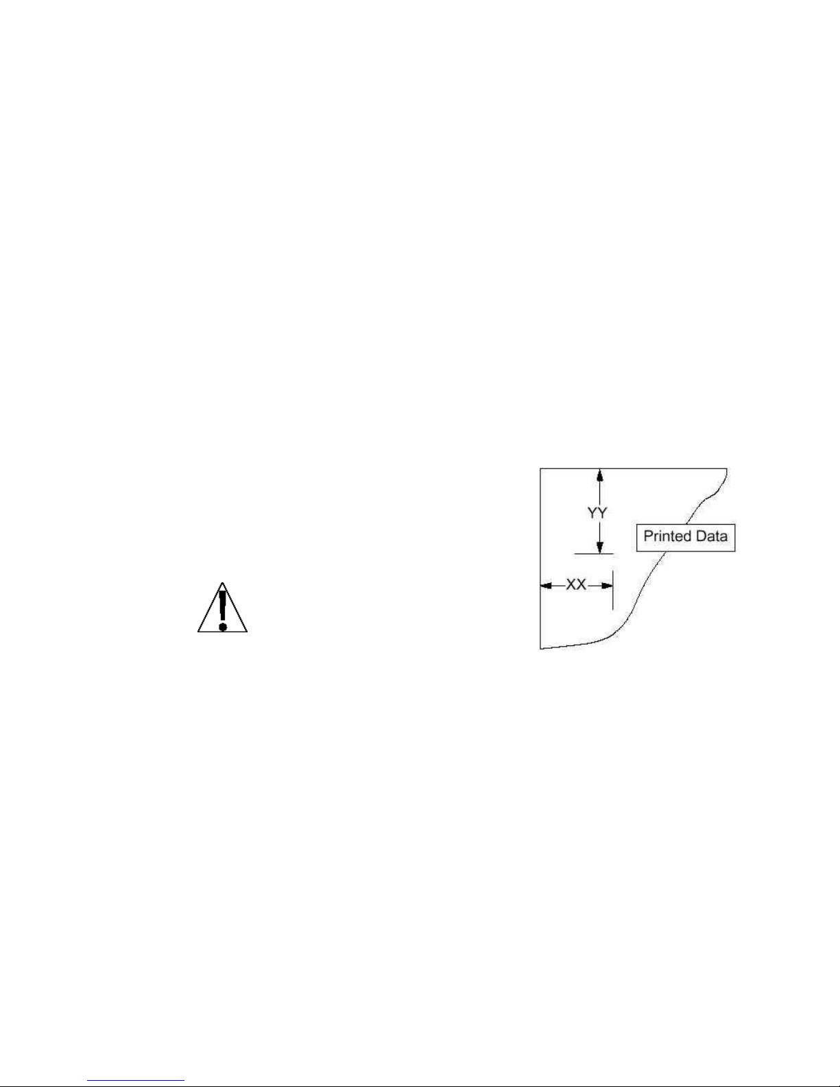
The general format for the input is A =
YY.XX where A is the character identifying
the data printed, YY is the number of lines
down and XX is the number of columns to
the right.
NOTE! Enter 00 in either the YY
or XX location to disable the
data from printing.
Port= (Select Serial Interface for Printing)
Press the TARE key to show the current setting. If the setting
displayed is acceptable, press the TARE key again to save it.
Otherwise, use the Fn/ key to toggle to a new setting and then press
the TARE key to save it. Allowable values are:
8400-M022-O1 Rev A 02/11
Page 47

Page 41
HoUr= (Time Print Location)
Press the TARE key to show the current setting for the Time
Print Location. If the setting displayed is acceptable, press the
TARE key again to save it. Otherwise, use the Fn/ and
UNITS/ keys to enter a new location and then press the
TARE key to save it.
dAtE= (Date Print Location)
Press the TARE key to show the current setting for the Date
Print Location. If the setting displayed is acceptable, press the
TARE key again to save it. Otherwise, use the Fn/ and
UNITS/ keys to enter a new location and then press the
TARE key to save it.
groSS= (Gross Weight Print Location)
Press the TARE key to show the current setting for the Gross
Weight Print Location. If the setting displayed is acceptable,
press the TARE key again to save it. Otherwise, use the Fn/
and UNITS/ keys to enter a new location and then press the
TARE key to save it.
JAC190 Installation & Technical
tArE= (Tare Weight Print Location)
Press the TARE key to show the current setting for the Tare
Weight Print Location. If the setting displayed is acceptable,
press the TARE key again to save it. Otherwise, use the Fn/
and UNITS/ keys to enter a new location and then press the
TARE key to save it.
nEt= (Net Weight Print Location)
Press the TARE key to show the current setting for the Net
Weight Print Location. If the setting displayed is acceptable,
press the TARE key again to save it. Otherwise, use the
Fn/ and UNITS/ keys to enter a new location and then press
the TARE key to save it.
8400-M022-O1 Rev A 02/11
Page 48

JAC190 Installation & Technical
Page 42
g ACC= (Gross Weight Accumulator Print Location)
Press the TARE key to show the current setting for the Gross Weight
Accumulator Print Location. If the setting displayed is acceptable, press
the TARE key again to save it. Otherwise, use the Fn/ and UNITS/
keys to enter a new location and then press the TARE key to save it.
n ACC= (Net Weight Accumulator Print Location)
Press the TARE key to show the current setting for the Net Weight
Accumulator Print Location. If the setting displayed is acceptable, press
the TARE key again to save it. Otherwise, use the Fn/ and UNITS/
keys to enter a new location and then press the TARE key to save it.
CoUnt= (Count "number of pieces on the scale" Print Location)
Press the TARE key to show the current setting for the Count Print
Location. If the setting displayed is acceptable, press the TARE key
again to save it. Otherwise, use the Fn/ and UNITS/ keys to enter a
new location and then press the TARE key to save it.
EACH= (Piece Weight Print Location)
Press the TARE key to show the current setting for the Piece Weight
Print Location. If the setting displayed is acceptable, press the TARE
key again to save it. Otherwise, use the Fn/ and UNITS/ keys to
enter a new location and then press the TARE key to save it.
CRLF= (Carriage Return Line Feed) - Data Format Termination
Data transmitted from the serial I/O port can be terminated with a single
carriage return and either no line feed or a single line feed command.
Press the TARE key to view the current setting. A YES on the display
means the data will be terminated with a carriage return AND a line feed
while a no on the display means the data will be terminated with a single
carriage return only.
If the setting displayed is acceptable, press the TARE key again to save
it. Otherwise, use the Fn/ key to toggle to a new setting and then press
the TARE key to save it.
8400-M022-O1 Rev A 02/11
Page 49

Page 43
EoP= (End-Of-Print Line Feeds)
At the end of a data transmission to a printer, the indicator can
transmit a pre-selected number of line feed commands to space the
paper in the printer to the desired position for withdrawal or for the
next print.
Press the TARE key to show the current setting for the End Of
Print Line Feeds. If the setting displayed is acceptable, press the
TARE key again to save it.
Otherwise, use the Fn/ and UNITS/ keys to enter a new
number of End-Of-Print linefeeds and then press the TARE key
to save it. Allowable settings are: 0 through 99
JAC190 Installation & Technical
8400-M022-O1 Rev A 02/11
Page 50

JAC190 Installation & Technical
Page 44
4.10 Fine Span Adjustment
IMPORTANT! The FSPAn (FSPAn?) mode requires a
load of 10% of Capacity on the scale before adjustments
can be made.
F span
Fine Span Adjustment (from SETUP Prompt)
1. If Fine Span Adjustment is desired, with the SETUP prompt
displayed, press the UNITS/ key until the display shows the
FSPAn prompt.
2. Place a calibrated test weight on the scale and press the TARE key.
3. The display will change to show the amount of the test weight, an F
will be displayed to the right of the annunciators and the
annunciators will alternately flash off and on.
4. Press the Fn/ key to increase the span by 0.5 division OR press
the UNITS/ key to decrease the span by 0.5 division.
5. Press the TARE key to exit the Fine Span Adjustment and
advance to the Hires? prompt.
Fspan?
Fine Span Adjustment (after pressing TARE at last Print prompt)
1. With fspan? displayed, press the TARE key.
2. The display will change to no.
3. Place a calibrated test weight on the scale.
4. Press the Fn/ key to toggle to yes and then press the TARE key.
5. The display will change to show the amount of the test weight, an F will
be displayed to the right of the annunciators and the annunciators will
alternately flash off and on.
6. Press the Fn/ key to increase the span by 0.5 division OR press the
UNITS/ key to decrease the span by 0.5 division.
7. Press the TARE key to exit the Fine Span Adjustment and advance
to the Hires? prompt.
8400-M022-O1 Rev A 02/11
Page 51

Page 45
4.11 Display High Resolution Weight
IMPORTANT! The Hires (Hires?) mode requires a load of 10%
of Capacity on the scale.
Hi res
High Resolution Weight (from SETUP Prompt)
1. If displaying High Resolution Weight is desired, with the SETUP
prompt displayed, press UNITS/ key until the display shows the
Hires prompt.
2. Place a calibrated test weight on the scale and press the TARE key.
3. The display will change to show the amount of the test weight in
"high resolution" mode (1/10 division), an h will be displayed to the
right of the annunciators and the annunciators will alternately flash
off and on.
JAC190 Installation & Technical
4. Press the Fn/ key to increase the span by 0.1 division OR press
the UNITS/ key to decrease the span by 0.1 division.
5. Press the TARE key to exit the Display High Resolution Weight
and advance to LoCoUt? prompt.
Hires?
High Resolution Weight (after TARE pressed at FSPAN prompt)
1. With Hires? displayed, press the TARE key.
2. The display will change to no.
3. Place a calibrated test weight on the scale.
4. Press the Fn/ key to toggle to yes and then press the TARE key.
5. The display will change to show the amount of the test weight in "high
resolution" mode (1/10 division), an h will be displayed to the right of
the annunciators and the annunciators will alternately flash off and on.
6. Press the Fn/ key to increase the span by 0.1 division OR press the
UNITS/ key to decrease the span by 0.1 division.
7. Press the TARE key to exit the Display High Resolution Weight and
advance to the LoCoUt? prompt.
8400-M022-O1 Rev A 02/11
Page 52

JAC190 Installation & Technical
Page 46
UnLoCd
LoCD
Key is Unlocked (Enabled)
Key is Locked (Disabled)
UnLoCd
LoCD
Key is Unlocked (Enabled)
Key is Locked (Disabled)
4.12 Key Lockout Feature
The Key Lockout Feature allows keys on the indicator to be disabled for
use by the operator “during normal operation”. During normal operation,
when the operator presses a locked key, the display will show LoCd for
about a 1/2 second and the key will be ignored.
NOTE! The Key Lockout Feature only disables keys for use
during normal operation, not setup and calibration.
LoCoUt
With LoCoUt displayed, press the TARE key. The display will change
to show 2ero=. Proceed to the 2ero= parameter.
LCoUt?
With LoCoUt? displayed, press the TARE key. The display will change
to no. Press the Fn/ key to toggle to yes and then press the TARE
key. The display will change to 2ero=. Proceed to the 2ero= parameter.
Otherwise, to skip the Key Lockout Feature setup, press the TARE key
to advance to the opt?. prompt.
2Ero= (ZERO Key)
Press the TARE key to show the current setting. If the setting displayed
is acceptable, press the TARE key again to save it. Otherwise, use the
Fn/ key to toggle to a new setting and then press the TARE key to
save it.
tAre= (TARE Key)
Press the TARE key to show the current setting. If the setting displayed
is acceptable, press the TARE key again to save it. Otherwise, use the
Fn/ key to toggle to a new setting and then press the TARE key to
save it.
8400-M022-O1 Rev A 02/11
Page 53

Page 47
net= (NET/GROSS Key)
UnLoCd
LoCD
Key is Unlocked (Enabled)
Key is Locked (Disabled)
UnLoCd
LoCD
Key is Unlocked (Enabled)
Key is Locked (Disabled)
UnLoCd
LoCD
Key is Unlocked (Enabled)
Key is Locked (Disabled)
UnLoCd
LoCD
Key is Unlocked (Enabled)
Key is Locked (Disabled)
Press the TARE key to show the current setting. If the setting
displayed is acceptable, press the TARE key again to save it.
Otherwise, use the Fn/ key to toggle to a new setting and then
press the TARE key to save it.
Units= (UNITS/ Key)
Press the TARE key to show the current setting. If the setting
displayed is acceptable, press the TARE key again to save it.
Otherwise, use the Fn/ key to toggle to a new setting and then
press the TARE key to save it.
JAC190 Installation & Technical
fUnC= (Fn/ Key)
Press the TARE key to show the current setting. If the setting
displayed is acceptable, press the TARE key again to save it.
Otherwise, use the Fn/ key to toggle to a new setting and then
press the TARE key to save it.
print= (PRINT Key)
Press the TARE key to show the current setting. If the setting
displayed is acceptable, press the TARE key again to save it.
Otherwise, use the Fn/ key to toggle to a new setting and then
press the TARE key to save it.
8400-M022-O1 Rev A 02/11
Page 54

JAC190 Installation & Technical
Page 48
UnLoCd
LoCD
Key is Unlocked (Enabled)
Key is Locked (Disabled)
on= (ON/OFF Key)
Press the TARE key to show the current setting. If the setting
displayed is acceptable, press the TARE key again to save it.
Otherwise, use the Fn/ key to toggle to a new setting and then press
the TARE key to save it.
IMPORTANT! When the ON/OFF key is locked, the display will
briefly show "LoCd" and then prompt the operator to press the
following keys in this order:
PRINT,
ZERO,
Fn/,
TARE ,
UNITS/,
NET/GROSS
If no key is pressed or the keys are pressed in the wrong order, the
indicator will turn back off.
8400-M022-O1 Rev A 02/11
Page 55

Page 49
4.13 Options Setup
0 = No Option Card Installed
1 = Serial Interface Option Card Installed
2 = Field Bus Option Card Installed
12 = 1200 Baud
24 = 2400 Baud
48 = 4800 Baud
96 = 9600 Baud
19 = 19.2k Baud
38 = 38.4k Baud
76 = 76.8k Baud
option
With opt displayed, press the TARE key. The display will change to
show opt=. Proceed to the opt= parameter.
opt?
With opt? displayed, press the TARE key. The display will change to
no. Press the Fn/ key to toggle to yes and then press the TARE key.
The display will change to opt=. Proceed to the opt= parameter.
Otherwise, to skip the Options Setup, press the TARE key to advance
to the fUnC?. prompt.
opt= (Option)
JAC190 Installation & Technical
Press the TARE key to show the current setting. If the setting displayed
is acceptable, press the TARE key again to save it. Otherwise, use the
Fn/ key to toggle to a new setting and then press the TARE key to
save it. Allowable values are:
IMPORTANT! The settings for the following prompts, baUd=,
Prty=, and Cont2= are only applied when the opt= parameter is
set to 0 or 1.
bAUd= (Optional Serial Interface Baud Rate)
Press the TARE key to show the current setting. If the setting displayed
is acceptable, press the TARE key again to save it. Otherwise, use the
Fn/ key to toggle to a new baud rate for the serial ports and then press
the TARE key to save it. Allowable settings are:
8400-M022-O1 Rev A 02/11
Page 56

JAC190 Installation & Technical
Page 50
0 = No Parity with 8 data bits
1 = Odd Parity with 7 data bits
2 = Even Parity with 7 data bits
YES = Continuous Output on Optional Serial Interface
no = No Continuous Output on Optional Serial Interface
0 = Continuous Output uses SMA format
1 = Continuous Output uses Nuweigh Scoreboard format
Prty= (Optional Serial Interface Parity Setting)
Press the TARE key to show the current setting. If the setting
displayed is acceptable, press the TARE key again to save it.
Otherwise, use the Fn/ key to toggle to a new setting and then
press the TARE key to save it. Allowable settings are:
Cont2= (Continuous Output on Optional Serial Interface)
Press the TARE key to show the current setting. If the setting
displayed is acceptable, press the TARE key again to save it.
Otherwise, use the Fn/ key to toggle to a new setting and then
press the TARE key to save it.
IMPORTANT! The setting for the type= are only applied
when the opt= parameter is set to 1 and Cont2= parameter
is set to YES.
tyPE= (Continuous Output Format)
Press the TARE key to show the current setting. If the setting
displayed is acceptable, press the TARE key again to save it.
Otherwise, use the Fn/ key to toggle to a new setting and then
press the TARE key to save it. Allowable settings are:
NOTE! Refer to the CONT1= Continuous Output on Serial
Interface, tYPE= parameter for description of output formats.
8400-M022-O1 Rev A 02/11
Page 57

Page 51
IMPORTANT! The following prompts, baUd= and Addr= are only
0 = 125k
1 = 250k
3 = 500k
displayed when the opt= parameter is set to 2.
bAUd= (Field Bus Option Baud Rate)
Press the TARE key to show the current setting. If the setting
displayed is acceptable, press the TARE key again to save it.
Otherwise, use the Fn/ key to toggle to a new baud rate for the serial
ports and then press the TARE key to save it. Allowable settings are:
addr= (Field Bus Option MAC Address)
Press the TARE key to show the current setting.
If the setting displayed is acceptable, press the
TARE key again to save it. Otherwise, use the
Fn/ key to toggle to a new setting and then press
the TARE key to save it. Allowable settings are:
0 through 63
JAC190 Installation & Technical
8400-M022-O1 Rev A 02/11
Page 58

JAC190 Installation & Technical
Page 52
Yes
No
Hold Function is Enabled
Hold Function is Disabled
Yes
No
Count Function is Enabled
Count Function is Disabled
4.14 Function Setup
fUnC
With FUnC displayed, press the TARE key. The display will change to
show Hold=. Proceed to the Hold = parameter.
FUnC?
With FUnC? displayed, press the TARE key. The display will change
to no. Press the Fn/ key to toggle to yes and then press the TARE
key. The display will change to HoLd=. Proceed to the HoLd=
parameter. Otherwise, to skip the Options Setup, press the TARE key
to advance to the Colors prompt.
IMPORTANT! The Hold, Count and Live Weight Features
should not be enabled if the Legal-For-Trade option (LFt=yes)
was selected during setup.
In addition, only one of the features Hold, Count, Peak Hold,
Checkweigher or Live Weight can be enabled at a time.
HoLd= (Hold Function)
Press the TARE key to show the current setting. If the setting
displayed is acceptable, press the TARE key again to save it.
Otherwise, use the Fn/ key to toggle to a new setting and then press
the TARE key to save it. Allowable values are:
CoUnt= (Count Function)
Press the TARE key to show the current setting. If the setting
displayed is acceptable, press the TARE key again to save it.
Otherwise, use the Fn/ key to toggle to a new setting and then press
the TARE key to save it. Allowable values are:
8400-M022-O1 Rev A 02/11
Page 59

Page 53
Ti-da= (Time and Date)
Yes
No
Time and Date is Enabled
Time and Date is Disabled
Yes
No
Peak Hold Function is
Enabled
Peak Hold Function is
Disabled
Yes
No
Checkweigher Function is
Enabled
Checkweigher Function is
Disabled
Yes
No
Live Weight Function is
Enabled
Live Weight Function is
Disabled
Press the TARE key to show the current setting. If the setting
displayed is acceptable, press the TARE key again to save it.
Otherwise, use the Fn/ key to toggle to a new setting and then
press the TARE key to save it. Allowable values are:
pHoLd= (Peak Hold Function)
Press the TARE key to show the current setting. If the setting
displayed is acceptable, press the TARE key again to save it.
Otherwise, use the Fn/ key to toggle to a new setting and then
press the TARE key to save it. Allowable values are:
JAC190 Installation & Technical
CHEC= (Checkweigher Function)
Press the TARE key to show the current setting. If the setting
displayed is acceptable, press the TARE key again to save it.
Otherwise, use the Fn/ key to toggle to a new setting and then
press the TARE key to save it. Allowable values are:
aCt= (Live Weight Function)
Press the TARE key to show the current setting. If the setting
displayed is acceptable, press the TARE key again to save it.
Otherwise, use the Fn/ key to toggle to a new setting and then
press the TARE key to save it. Allowable values are:
8400-M022-O1 Rev A 02/11
Page 60

JAC190 Installation & Technical
Page 54
Yes
No
Weight Accumulation
Function is Enabled
Weight Accumulation
Function is Disabled
aCCU= (Weight Accumulation Function)
Press the TARE key to show the current setting. If the setting
displayed is acceptable, press the TARE key again to save it.
Otherwise, use the Fn/ key to toggle to a new setting and then press
the TARE key to save it. Allowable values are:
8400-M022-O1 Rev A 02/11
Page 61

Page 55
4.15 Display Backlight Color Setup
0 = No Backlight
1 = Red Backlight
2 = Green Backlight
3 = Yellow Backlight
4 = Blue Backlight
0 = No Backlight
1 = Red Backlight
2 = Green Backlight
3 = Yellow Backlight
4 = Blue Backlight
CoLorS
With Colors displayed, press the TARE key. The display will change to
show dflt=. Proceed to the dflt= parameter.
Color?
With Color? displayed, press the TARE key. The display will change to
no. Press the Fn/ key to toggle to yes and then press the TARE key.
The display will change to dflt=. Proceed to the dflt= parameter.
Otherwise, to skip the Display Backlight Color setup, press the TARE
key to reset the indicator and return to the normal weight display.
JAC190 Installation & Technical
dflt= (Default Display Backlight Color)
Press the TARE key to show the current setting. If the setting displayed
is acceptable, press the TARE key again to save it. Otherwise, use the
Fn/ key to toggle to a new setting and then press the TARE key to
save it. Allowable settings are:
Under= (Checkweigher “Under” Backlight Color)
Press the TARE key to show the current setting. If the setting displayed
is acceptable, press the TARE key again to save it. Otherwise, use the
Fn/ key to toggle to a new setting and then press the TARE key to
save it. Allowable settings are:
8400-M022-O1 Rev A 02/11
Page 62

JAC190 Installation & Technical
Page 56
0 = No Backlight
1 = Red Backlight
2 = Green Backlight
3 = Yellow Backlight
4 = Blue Backlight
0 = No Backlight
1 = Red Backlight
2 = Green Backlight
3 = Yellow Backlight
4 = Blue Backlight
aCCpt= (Checkweigher “Accept” Backlight Color)
Press the TARE key to show the current setting. If the setting
displayed is acceptable, press the TARE key again to save it.
Otherwise, use the Fn/ key to toggle to a new setting and then
press the TARE key to save it. Allowable settings are:
oer= (Checkweigher “Over” Backlight Color)
Press the TARE key to show the current setting. If the setting
displayed is acceptable, press the TARE key again to save it.
Otherwise, use the Fn/ key to toggle to a new setting and then
press the TARE key to save it. Allowable settings are:
8400-M022-O1 Rev A 02/11
Page 63
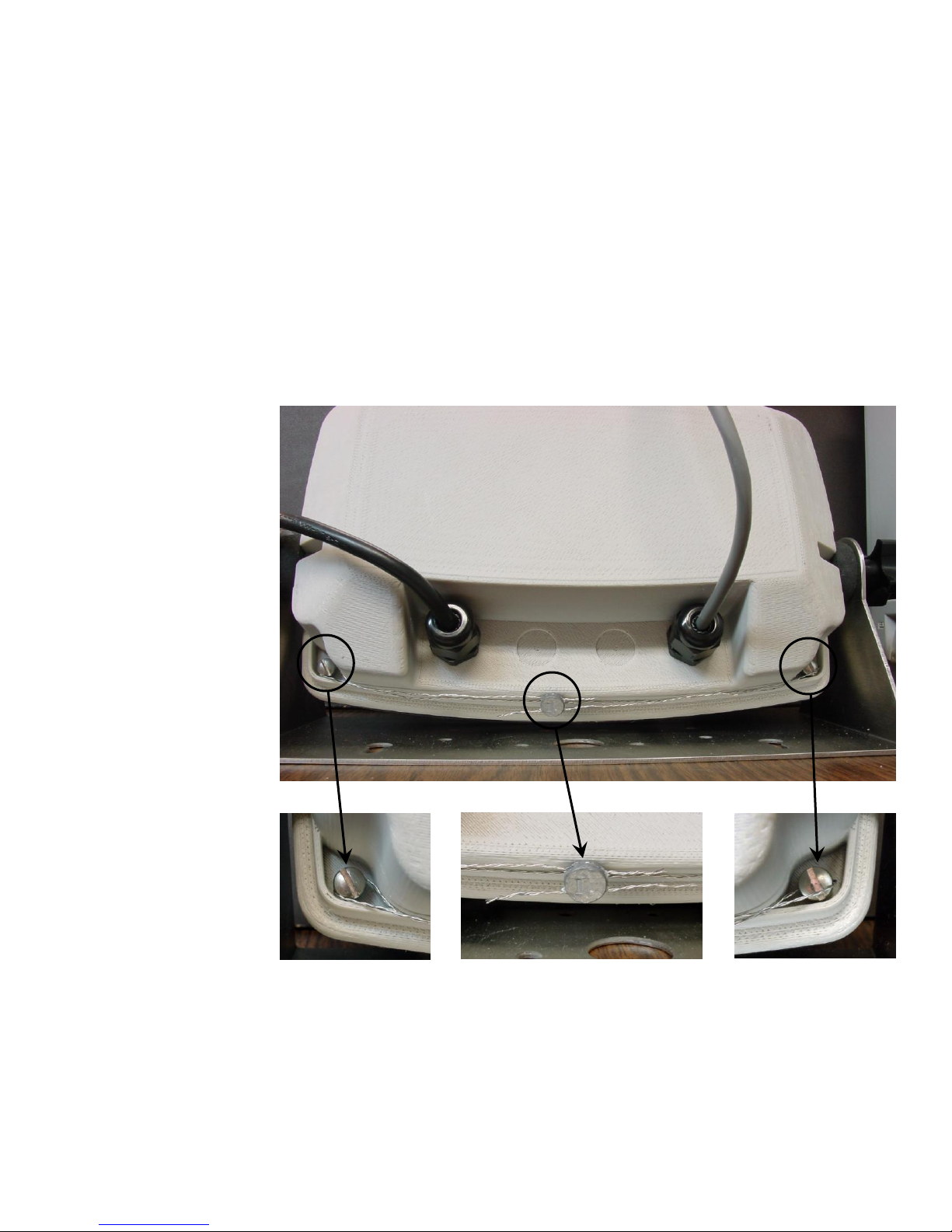
Page 57
5. CALIBRATION SEAL
5.1 Installing the Calibration Seal
If your Model JAC190 Weight Indicator is used in a commercial application
it must be tested and sealed by your local weights and measurements
official. The JAC190 is designed to accept a lead and wire security seal to
prevent unauthorized access to the calibration adjustments. Refer to
Figure No. 9, 10, 11 and 12 for details on the installation of the seal.
Figure No. 9
JAC190 Installation & Technical
Figure No. 10 Figure No. 11 Figure No. 12
8400-M022-O1 Rev A 02/11
Page 64
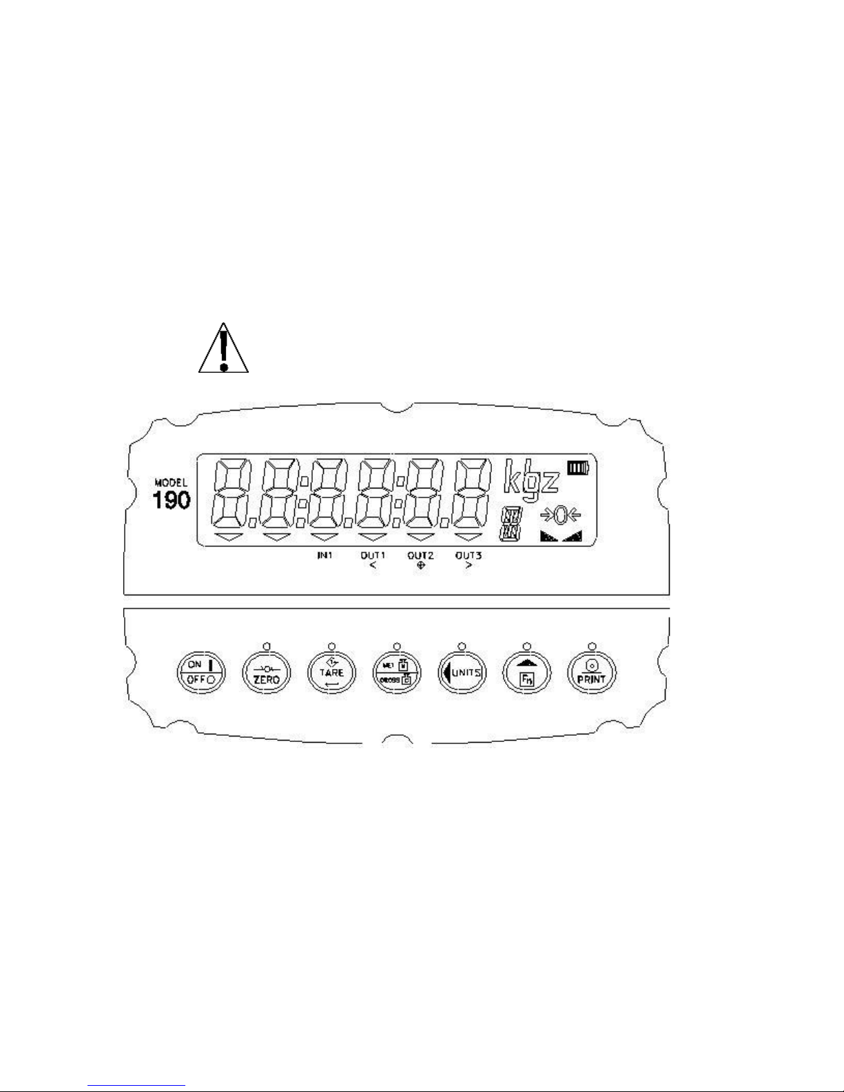
JAC190 Installation & Technical
Page 58
6. KEYPAD
6.1 Standard Key Functions
The Model JAC190 is equipped with a 7-key Capacitive Touch keypad.
The keypad is used to enter commands and data into the indicator. This
section describes each key along with its normal function. It is helpful to
refer to the actual indicator while reading this section.
The Model JAC190 use a capacitive touch keypad that
requires a “finger touch” to function. The keypad will not
operate with other items such as pen, pencil or tools.
Figure No. 13
8400-M022-O1 Rev A 02/11
Page 65
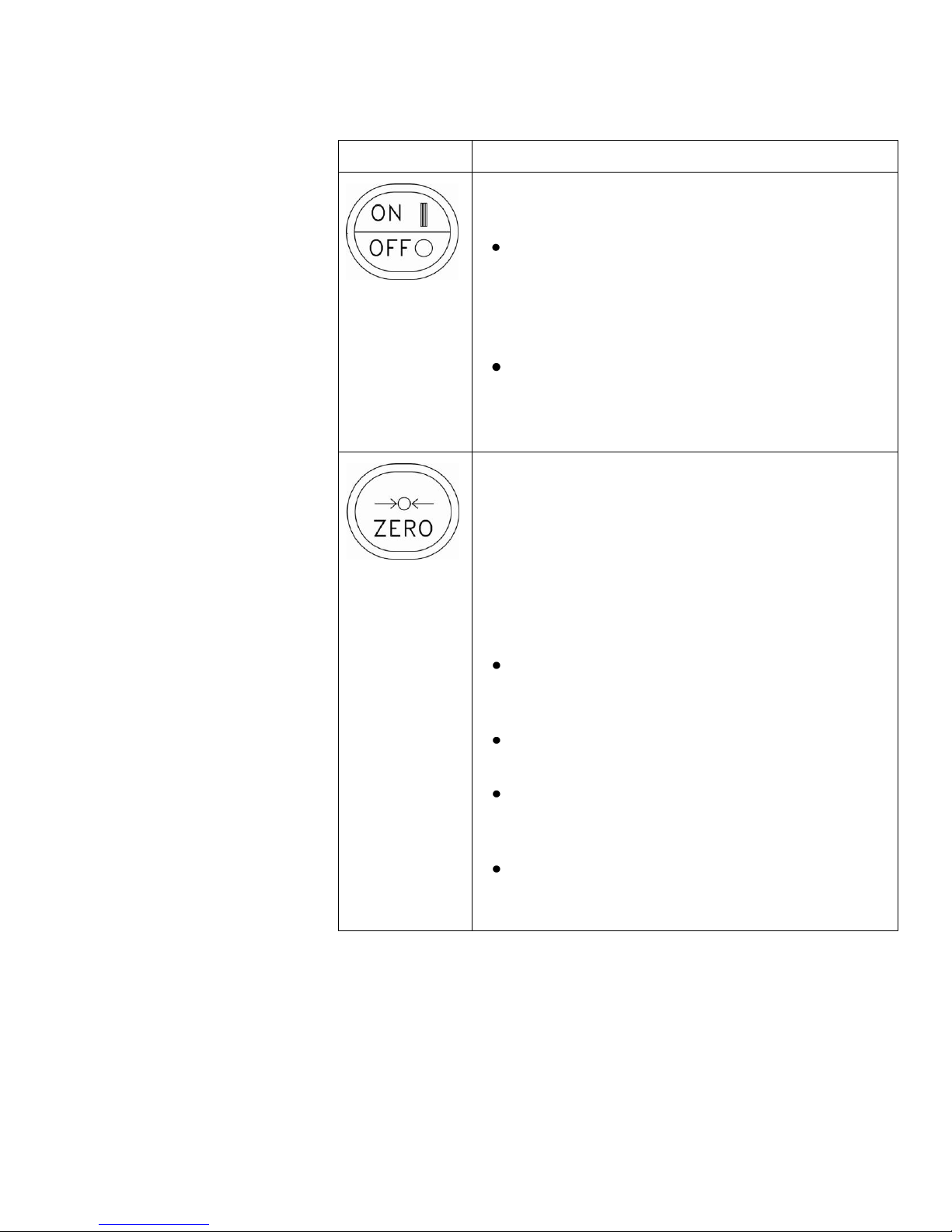
JAC190 Installation & Technical
Page 59
Key
Description
ON/OFF: The ON/OFF key is used to turn the
indicator on and off.
Press the ON/OFF key when the indicator is
off to turn the indicator ON. The JAC190 will
perform a display test (turn on all segments)
and then show the model number and
software version.
If the indicator is already on, press the
ON/OFF key and hold for 2 to 3 seconds.
When the display shows OFF, release the
key to turn the indicator OFF.
ZERO: The ZERO key is used to zero the weight
display. Up to the selected limit of 4% or 100%
of the scale’s capacity can be zeroed. This limit
is selected during the setup and calibration of the
indicator.
Note that the indicator will not respond to
pressing the ZERO key unless the weight display
is stable.
When displaying a Tare weight, pressing
the ZERO key will clear the Tare value and
set the display to Gross mode.
When displaying the Peak weight, pressing
the ZERO key will clear the Peak weight.
When displaying the Gross accumulator,
pressing the ZERO key will clear the Gross
accumulator.
When displaying the Net accumulator,
pressing the ZERO key will clear the Net
accumulator.
8400-M022-O1 Rev A 02/11
Page 66
JAC190 Installation & Technical
Page 60
Key
Description
TARE (Enter): The TARE key is used during
normal operation to store the current Gross weight as
the new Tare weight. The display will change to the Net
weight and the Net annunciator will turn on.
Pressing the TARE key when in the Net weight
mode will cause the display to show the Tare
weight.
During Setup, pressing the TARE key will
display the current setting of the parameter.
Pressing the TARE key a second time (after
changing parameter values or settings), signals
completion of the entry of data and causes the
indicator to process the data entered.
NET/GROSS: The NET/GROSS key is used to toggle
between the Gross and Net weight modes. The
selected mode is indicated by turning on the appropriate
annunciator on the display.
Note that if no valid tare weight has been entered,
pressing the NET/GROSS key will cause a momentary
display error (notArE) and the indicator will remain in
the Gross weight mode.
When in Hold, Count, Peak weight, Live weight, or
Accumulator display mode, press the NET/GROSS key
to return the display to normal weight display mode.
UNITS/ (Left Arrow): The UNITS/ key is used for
several functions.
In normal operation, the UNITS/ key is used to
select the units in which the weight is to be
displayed. The available units of measure ("unit1"
and "unit2") are selected in setup. The available
units include pounds, ounces, kilograms, and
grams.
During setup, the UNITS/ key is used to advance the
cursor left to the next position when inputting setup
parameters.
8400-M022-O1 Rev A 02/11
Page 67
JAC190 Installation & Technical
Page 61
Key
Description
Fn/ (Up Arrow): The Fn/ key is used for
several functions.
During indicator setup, when a setup
parameter (not a parameter value or setting)
is displayed, pressing the Fn/ key will
"backup" to the previous parameter prompt.
Also during setup, when a parameter value
or setting is displayed, pressing the Fn/
key will "toggle" between the different
available values or settings for that
parameter.
In normal operation, the Fn/ key is used in
conjunction with the other keys on the keypad to
access additional indicator features.
PRINT: Pressing the PRINT key during a
weighing operation, will add the displayed Gross
weight, or Net weight to the associated
accumulator and send print ticket data to the
serial interface selected during setup (see
Port=).
NOTE! The indicator will not respond to
pressing the PRINT key unless the weight
display is stable.
If displaying Gross weight, the only weight
printed is Gross weight.
If displaying Net weight, the Gross, Tare,
and Net weights are printed.
When in Gross weight accumulator display
mode, pressing the PRINT key will print the
Gross weight accumulator.
When in Net weight accumulator display
mode, pressing the PRINT key will print the
Net weight accumulator.
When in Peak weight display mode,
pressing the PRINT key will print the Peak
weight.
8400-M022-O1 Rev A 02/11
Page 68

JAC190 Installation & Technical
Page 62
Function
Display
Description or Setting
Hold
HoLd X
X will be 1 if enabled, 0 if disabled
Count
CoUnt X
X will be 1 if enabled, 0 if disabled
Time and Date
HH:MM A
HH=hours, MM=minutes,
A for AM, P for PM
MM.DD.YY
(usa=yes)
DD.MM.YY
(usa=no)
MM=month, DD=day, YY=last two
digits of year
Peak Hold
PhoLd X
X will be 1 if enabled, 0 if disabled
Checkweigher
Lo=
Minimum acceptable weight prompt
X*
= minimum acceptable weight value.
*
When the value for Lo= is greater
than 0, the Checkweigher function
is enabled.
Hi=
Maximum acceptable weight prompt.
This prompt is displayed, when the
value for Lo= is greater than 0.
X = maximum acceptable weight value
Live Weight
Act X
X will be 1 if enabled, 0 if disabled
Weight
Accumulation
ACCU X
X will be 1 if enabled, 0 if disabled
Backlight Color
Colors
Backlight Colors for normal operation
and Checkweigher results
6.2 Fn/ Key Functions
The Fn/ key is used to select several additional functions that may have
been enabled during the setup and calibration of the indicator. Those
functions include: Hold, Count, Time and Date, Peak Hold, Checkweigher,
Live Weight, Weight Accumulation and Backlight Color.
IMPORTANT! The Hold, Count and Live Weight functions cannot
be enabled if the Legal-For-Trade option (LFt=yes) was selected
during setup.
In addition, only one of the functions Hold, Count, Peak Hold,
Checkweigher or Live Weight can be enabled at a time.
Description of Fn/ Key Functions
8400-M022-O1 Rev A 02/11
Page 69

Page 63
6.3 Fn/ Key Combination Features
The Fn/ key is also used in combination with the other keys on the keypad
to access additional indicator features. Those features and their associated
key combinations are as follows:
Fn/, ZERO KEY
This combination will enter the Review mode of Setup and Calibration.
Refer to the Setup Review section of this manual for details.
Fn/, NET/GROSS KEY
This combination will allow viewing of the Audit Trail Counters. Refer to
the View Event Counters section of this manual for details.
Fn/, UNITS/ KEY
JAC190 Installation & Technical
This combination will enter the Test Mode/Diagnostics Feature. This
feature is used to conduct a test of all display elements and perform
self-diagnostics. Refer to the Test/Mode/Diagnostics section of this
manual for details.
Fn/, PRINT KEY
This key combination is used for several functions. Print formats are
selected by using the Fn/ key and PRINT keys in combination. Note
that when the PRINT key is pressed the indicator looks for the selected
format. If no visual ticket is found it reverts to the print tab settings.
Refer to section 9.2.1 for details on Ticket Format Selection.
This key combination is also used to enter the Preset Weight
Comparators “PWC” weight values. Refer to section 9.3 for details on
Preset Weight Comparators.
8400-M022-O1 Rev A 02/11
Page 70

JAC190 Installation & Technical
Page 64
Symbol
Name
Description
0
ZERO
This annunciator is turned on to
indicate that the weight displayed is
within ± 1/4 division of true zero.
STABLE
This annunciator is turned on when
the weight display is stable. When
off, it means that the change in
successive weight samples is
greater than the motion limits
selected during setup.
N
NET
This annunciator is turned on when
the displayed weight is Net weight
(Gross weight less Tare weight).
G
GROSS
This annunciator is turned on to
show that gross weight is displayed.
Gross weight will be displayed when
no tare weight is stored.
T
TARE
This annunciator is turned on to
show that the displayed weight is the
tare weight.
lb
pounds
This annunciator is located to the
right of the weight display and is
turned on to show that the displayed
weight unit is pounds.
oz
ounces
This annunciator is located to the
right of the weight display and is
turned on to show that the displayed
weight unit is ounces.
7. ANNUNICATORS
7.1 Annunicators
The Model JAC190 is equipped with annunciators that are turned on to
indicate that the display is in the mode corresponding to the annunciator
label or that the status indicated by the label is active. This section
describes each annunciator. Refer to Figure No. 13 for the location of the
annunciators.
8400-M022-O1 Rev A 02/11
Page 71

JAC190 Installation & Technical
Page 65
kg
kilograms
This annunciator is located to
the right of the weight display
and is used to indicate that
the displayed unit of weight
measurement is kilograms.
g
grams
This annunciator is located to
the right of the weight display
and is used to indicate that
the displayed unit of weight
measurement is grams.
C
COUNT
This annunciator shows that
the display is in the Count
mode and the value displayed
is in pieces (the count
quantity) and not weight.
G and A
or
N and A
ACCUMULATOR
This annunciator shows that
the displayed value is the
content of the accumulator.
IN1
DIGITAL INPUT
This annunciator is used to
signal that a remote key
function has been activated.
Note that this annunciator is
active only when the Digital
Input feature has been
enabled. Refer to the d in
parameter in Setup.
OUT1
UNDER
This annunciator is used to
signal that the displayed
weight is less than the
minimum value of acceptable
weight used in the
Checkweigher feature or that
preset 1 is active.
Note that this annunciator is
active only when the
Checkweigher feature or the
preset feature has been
enabled. Refer to the d oUt
parameter in Setup.
8400-M022-O1 Rev A 02/11
Page 72

JAC190 Installation & Technical
Page 66
OUT2
ACCEPT
This annunciator is used to signal
that the displayed weight is within
the acceptable weight limits for the
Checkweigher feature.
That is, the weight is equal to or
greater than the minimum
acceptable weight and equal to or
less than the maximum acceptable
weight.
This annunciator is also used to
indicate that preset 2 is active.
Note that this annunciator is active
only when the Checkweigher feature
or the preset feature has been
enabled. Refer to the d oUt
parameter in Setup.
OUT3
OVER
This annunciator is used to signal
that the displayed weight is equal
to or greater than the minimum
value of over weight used in the
Checkweigher feature
This annunciator is also used to
indicate that preset 3 is active.
Note that this annunciator is active
only when the Checkweigher feature
or the preset feature has been
enabled. Refer to the d oUt
parameter in Setup.
8400-M022-O1 Rev A 02/11
Page 73
Page 67
7.2 Battery Status
Number of Bars
Level of Charge
4
100%
3
75%
2
50%
1
25%
Note that as the battery approaches full discharge, the outline of
the battery will start to flash.
JAC190 Installation & Technical
The battery status indicator will be displayed when
a battery pack is installed. The number of bars
indicates the level of charge.
NOTE! When the indicator is connected to an external
power supply and is charging the battery, the charge level
status bars will scroll.
8400-M022-O1 Rev A 02/11
Page 74

JAC190 Installation & Technical
Page 68
Td=
Time and Date (Select 12 or 24 hour clock)
d in=
Digital Input (Disable or Select key function)
d out=
Digital Output (Disable or Select Preset/Checkweigher
function)
SLEEP=
Sleep Mode (Disable or Select number of minutes
before entering sleep mode)
A off=
Auto Shutoff (Disable or Select number of minutes
before automatic shutoff)
Sio?
Serial Input/Output Configuration
(Select YES or NO)
baUd=
Select Serial Port Baud Rate
prty=
Select Serial Port Parity
Cont1=
Enable or Disable Continuous Output to the Serial Port
type=
If Cont1=YES
(Select Continuous Output Format, SMA or Nuweigh
Scoreboard)
8. INDICATOR SETUP REVIEW
The JAC190 indicator allows several operational parameters to be
reviewed and changed without breaking the calibration seal.
8.1 Accessing Setup Review
1. With the indicator ON, press Fn/ key and then the ZERO key.
2. The display will change to show td= (the prompt for selection of a 12
or 24 hour clock).
3. Press the TARE key to show the current setting. If the setting
displayed is acceptable, press the TARE key again to save it.
Otherwise, use the Fn/ key to toggle to a new setting and then
press the TARE key to save it and advance to the next prompt.
4. To exit Setup Review, press the TARE key to step through the
remaining prompts OR at anytime, cycle the power (press the
ON/OFF key twice).
8400-M022-O1 Rev A 02/11
Page 75

JAC190 Installation & Technical
Page 69
print?
Print Tab Settings Configuration (Select YES or NO)
port=
Disable or Select Serial Interface for Printing
HoUr=
Time Print Location
date=
Date Print Location
gross=
Gross Weight Print Location
tare=
Tare Weight Print Location
net=
Net Weight Print Location
g aCC=
Gross Weight Accumulator Print Location
n aCC=
Net Weight Accumulator Print Location
CoUnt=
Count "number of pieces on the scale" Print Location
EACH=
Piece Weight Print Location
CRLF=
Carriage Return Line Feed (Data Format Termination)
EoP=
End-Of-Print Line Feeds
opt?
Options Configuration (Select YES or NO)
opt=
Select Option Card Installed
baUd=
Select Option Card Baud Rate when Opt= 0 or 1
Prty=
Select Option Card Parity when Opt= 0 or 1
Cont2=
Enable or Disable Continuous Output to the Option Port
type=
If Opt=1 and Cont2=YES
(Select Continuous Output Format, SMA or Nuweigh
Scoreboard)
baUd=
Select Field Bus Option Baud Rate when Opt= 2
Addr=
Select Field Bus Option MAC Address when Opt= 2
Color?
Display Backlight Color Setup (Select YES or NO)
dflt=
Select Default Backlight Color
Under=
Select Checkweigher “Under“ Backlight Color
ACCPt=
Select Checkweigher “Accept“ Backlight Color
oEr=
Select Checkweigher “Over“ Backlight Color
8400-M022-O1 Rev A 02/11
Page 76
JAC190 Installation & Technical
Page 70
0 = print tab settings
1 = visual ticket format
#2
10:19 09/23/2010
100.00 lb G
20.00 lb T
80.00 lb N
0.00 lb GROSS ACCUM
272.00 lb NET ACCUM
9. OPERATION
9.1 Ticket Format Selection
The JAC190 includes support for visual tickets. Visual tickets are
designed by the PC based programs Visual Print or nControl and then
downloaded to the indicator.
The JAC190 allows one programmable format in addition to the standard
print tab settings format.
1. Press the Fn/ key then the PRINT key.
2. The display will change to show Prt=.
3. Press the TARE key to show the current value.
4. If the setting displayed is acceptable, press the TARE key again
to save it.
5. Otherwise, press the Fn/ key to "toggle" between the different
available settings and then press the TARE key to save it.
Allowable settings are:
NOTE! When a print format is selected, it will remain active
until changed by the operator.
TICKET EXAMPLE
8400-M022-O1 Rev A 02/11
Page 77

Page 71
9.2 Preset Weight Comparators
The Model JAC190 indicator has three (3) outputs, which can be
configured during setup to perform as Preset Weight Comparators
“PWC”. The output state of each PWC (before reaching the preset
weight) is defined in section 4.4 SETUP, the d out= (Digital Output)
parameter.
With the PWC feature selected, during operation the indicator will
compare each enabled preset weight value with the displayed weight and
then output a signal for each preset based on the comparison results.
9.2.1 Entering Preset Weight Comparators Values
1. To enter the Preset Weight Comparators values, simultaneously
press the Fn/ key and the PRINT key.
2. Press the TARE key.
JAC190 Installation & Technical
3. The display will change to show Prt= (the prompt for Print Ticket
Format selection). Refer to section 9.1 for details on selecting a
Print Ticket Format.
4. Press the TARE key again to skip the Print Ticket Format
selection.
5. The display will change to show PSEt1=.
6. Press the TARE key to display the current value of the first
preset weight value.
7. If the setting displayed is acceptable, press the TARE key again
to save it.
8. Otherwise, use the Fn/ and UNITS/ keys to enter a new value
for the preset weight.
9. When the desired value is displayed, press the TARE key to
save it.
10. Continue with this procedure until a value for each preset to be used
has been entered.
11. After the last preset value has been entered and the TARE key
pressed, the indicator will return to the weight display.
8400-M022-O1 Rev A 02/11
Page 78

JAC190 Installation & Technical
Page 72
9.2.2 Preset Weight Comparators Operation
The preset weight comparators are used to control peripheral
devices used in some form of process control. The number of
comparators used depends upon system needs.
For example, in a simple filling operation, a single comparator may
be used to open or close a gate which dumps material on the scale.
In a more complex application, more comparators may be used for
high speed/low speed filling.
The d out= (Digital Output) setup parameter selects how many
comparators are being used and the state of the output when the
scale weight is below the preset target or cutoff weight. The output
can be in one of two states: connected to the common pin on the i/o
connector or not connected to the common pin on the i/o connector.
When the scale weight is greater than or equal to the cutoff weight,
the output will change state.
8400-M022-O1 Rev A 02/11
Page 79

Page 73
9.3 Hold Function
1 = Hold Function Active
0 = Hold Function Not Active
With the Hold function enabled during setup of the indicator, the
function must be activated before it can be used.
Refer to section 4.15 Function Setup, the FUnC (FUnC?) parameter to
enable the Fn/ key Hold function.
NOTE! This function is not available when Legal-For-trade (LFt=yes) has
been selected in setup. In addition, only one of the functions Hold, Count,
Peak Hold, Checkweigher or Live Weight can be active at a time.
9.3.1 Activate Hold Function
1. Press and hold the Fn/ key until the display blanks.
2. Once the display blanks, release the Fn/ key
JAC190 Installation & Technical
3. The display will change to show Hold X, the prompt and status of the
Hold function.
4. If the setting displayed is acceptable, press the TARE key to save
it. Otherwise, use the Fn/ key to toggle to a new setting and then
press the TARE key to save it.
5. Repeatedly press the TARE key to step through the remaining
function prompts until the indicator returns to the weight display.
9.3.2 Hold Function Operation
1. With the Hold function enabled and activated, momentarily press the
Fn/ key and the display will lock at its current weight reading.
2. Press the PRINT key to print the held reading.
3. Press the NET/GROSS, ZERO, TARE , or UNITS/ key to release
the hold and return to the weight display.
8400-M022-O1 Rev A 02/11
Page 80

JAC190 Installation & Technical
Page 74
1 = Count Function Active
0 = Count Function Not Active
9.4 Count Function
With the Count function enabled during setup of the indicator, the
function must be activated before it can be used.
Refer to section 4.15 Function Setup, the FUnC (FUnC?) parameter to
enable the Fn/ key Count function.
NOTE! This function is not available when Legal-For-trade (LFt=yes) has
been selected in setup. In addition, only one of the functions Hold, Count,
Peak Hold, Checkweigher or Live Weight can be active at a time.
9.4.1 Activate Count Function
1. Press and hold the Fn/ key until the display blanks.
2. Once the display blanks, release the Fn/ key
3. Press the TARE key until the display shows CoUntX, the prompt
and status of the Count function.
4. If the setting displayed is acceptable, press the TARE key to save
it. Otherwise, use the Fn/ key to toggle to a new setting and then
press the TARE key to save it.
5. Repeatedly press the TARE key to step through the remaining
function prompts until the indicator returns to the weight display.
9.4.2 Count Function Operation
1. Press the Fn/ key. If no average piece weight has been set, the
display will show Add= 5.
2. Repeatedly press the Fn/ key to cycle through the sample sizes
5, 10, 25, 50, and 75 pieces.
3. Alternatively, press the UNITS/ key. The digit will start to flash.
4. Repeatedly press the Fn/ key until the desired value is displayed.
5. Press the UNITS/ key to select the next digit.
6. Add the number of pieces to the scale and press the TARE key.
7. The display will change to show the number of pieces on the scale.
8400-M022-O1 Rev A 02/11
Page 81

JAC190 Installation & Technical
Page 75
8. Additional pieces may be added and the display will show the
total number of pieces.
9. Press the NET/GROSS key to return to the weight display.
After the average piece weight has been set, pressing the
Fn/ key will go directly to displaying piece count.
To change the average piece weight, press the Fn/ key
a second time and the Add= 5 prompt will be displayed.
To quit the sampling process without changing the
average piece weight, set the sample size to 0 and press
the TARE key.
8400-M022-O1 Rev A 02/11
Page 82

JAC190 Installation & Technical
Page 76
9.5 Time and Date Functions
With the Time and Date function enabled during setup of the indicator,
the function must be activated before it can be used.
Refer to section 4.15 Function Setup, the FUnC (FUnC?) parameter to
enable the Fn/ key Time and Date function.
NOTE! With USA=yes, the date format is month-day-year. If USA=no,
the date format is day-month-year.
9.5.1 Set the Time
1. Press and hold the Fn/ key until the display blanks.
2. Once the display blanks, release the Fn/ key
3. Press the TARE key until the display shows the time prompt,
HH:MM X. Note that X will be A for AM or P for PM.
4. If the time displayed is correct, press the TARE key to save it.
5. Otherwise, press the Fn/ key to toggle between A and P.
6. Next, press the UNITS/ key to select the digit of the minutes or hour
to change.
7. Press the Fn/ key to change the digit's value.
8. When the correct time is displayed, press the TARE key to save it.
9. Repeatedly press the TARE key to step through the remaining
function prompts until the indicator returns to the weight display.
9.5.2 Set the Date
1. Press and hold the Fn/ key until the display blanks.
2. Once the display blanks, release the Fn/ key.
3. Press the TARE key until the display shows the date prompt.
4. If the date displayed is correct, press the TARE key to save it.
5. Otherwise, use the UNITS/ key to select the digit of the month, day
or year to change and then use the Fn/ key to change the digit's
value.
6. When the correct date is displayed, press the TARE key to save it.
7. Repeatedly press the TARE key to step through the remaining
function prompts until the indicator returns to the weight display.
8400-M022-O1 Rev A 02/11
Page 83

Page 77
9.6 Peak Hold Function
1 = Peak Hold Function Active
0 = Peak Hold Function Not Active
With the Peak Hold function enabled during setup of the indicator, the
function must be activated before it can be used.
Refer to section 4.15 Function Setup, the FUnC (FUnC?) parameter to
enable the Fn/ key Hold function.
NOTE! Only one of the functions Hold, Count, Peak Hold, Checkweigher
or Live Weight can be active at a time.
9.6.1 Activate Hold Function
1. Press and hold the Fn/ key until the display blanks.
2. Once the display blanks, release the Fn/ key
3. The display will change to show PHoldX, the prompt and status of the
Peak Hold function.
JAC190 Installation & Technical
4. If the setting displayed is acceptable, press the TARE key to save
it. Otherwise, use the Fn/ key to toggle to a new setting and then
press the TARE key to save it.
5. Repeatedly press the TARE key to step through the remaining
function prompts until the indicator returns to the weight display.
9.6.2 Peak Hold Function Operation
When the Peak Hold function is active, the largest weight value
measured since Peak Hold was activated (or cleared) will be stored.
1. To display the peak value, momentarily press the Fn/ key.
2. To zero the peak value, make sure there is no load on the scale and
press the ZERO key.
3. Press the NET/GROSS key to return to the weight display.
8400-M022-O1 Rev A 02/11
Page 84

JAC190 Installation & Technical
Page 78
0 = Checkweigher Function Not Active
XXXXX = Minimum Acceptable Weight (Checkweigher is Active)
9.7 Checkweigher
The Model JAC190 indicator has logic level outputs that can be used to
control peripheral devices used to signal when the weight is within preset
limits. The output state of the Checkweigher (before reaching the preset
weight) is defined in section 4.4 SETUP, the d out= (Digital Output)
parameter. Note that these outputs are at logic level and cannot drive
external devices directly. Solid-state relays can be used to accept the
logic level outputs from the JAC190 and in turn, drive the external
device.
With the Checkweigher function enabled during setup of the indicator,
the function must be activated before it can be used.
Refer to section 4.15 Function Setup, the FUnC (FUnC?) parameter to
enable the Fn/ key Hold function.
NOTE! Only one of the functions Hold, Count, Peak Hold, Checkweigher
or Live Weight can be active at a time.
9.7.1 Activate Checkweigher and Set Minimum Acceptable Weight Value
1. Press and hold the Fn/ key until the display blanks.
2. Once the display blanks, release the Fn/ key
3. The display will change to show the first function prompt.
4. Repeatedly press the TARE key until the Lo= prompt is displayed.
5. Press the TARE key once again.
6. The display will show the current value for the minimum acceptable
weight.
7. If the setting displayed is acceptable, press the TARE key to save
it.
8. Otherwise, use the Fn/ and UNITS/ keys to enter a new value for
the minimum acceptable weight.
9. When the desired value is displayed, press the TARE key to save
it.
10. Repeatedly press the TARE key to step through the remaining
function prompts until the indicator returns to the weight display.
9.7.2 Entering Maximum Acceptable Weight Value
8400-M022-O1 Rev A 02/11
Page 85

JAC190 Installation & Technical
Page 79
1. Press and hold the Fn/ key until the display blanks.
2. Once the display blanks, release the Fn/ key
3. The display will change to show the first function prompt.
4. Repeatedly press the TARE key until the Hi= prompt is
displayed.
5. Press the TARE key once again.
6. The display will show the current value for the maximum
acceptable weight.
7. If the setting displayed is acceptable, press the TARE key
again to save it.
8. Otherwise, use the Fn/ and UNITS/ keys to enter a new
value for the maximum acceptable weight.
9. When the desired value is displayed, press the TARE key
to save it.
10. Repeatedly press the TARE key to step through the
remaining prompts until the indicator returns to the weight
display.
9.7.3 Checkweigher Operation
With the Checkweigher function enabled and activated, during operation
the indicator will compare the displayed weight with the preset values
and display the results as under, accept, or over.
When the displayed weight is less than the minimum acceptable weight,
the arrow over OUT1 < (the UNDER annunciator) will turn on and
the display will change to the color selected in section 4.15, Display
Backlight Color Setup.
When the displayed weight is greater than the maximum acceptable
weight, the arrow over OUT3 > (the OVER annunciator) will turn on
and the display will change to the color selected in section 4.15,
Display Backlight Color Setup.
When the displayed weight is within the range from minimum acceptable
weight to maximum acceptable weight, the arrow over OUT2 (the
ACCEPT annunciator) will turn on and the display will change to the
color selected in section 4.15, Display Backlight Color Setup.
9.8 Live Weight Function
With the Live Weight function enabled during setup of the indicator, the
function must be activated before it can be used.
8400-M022-O1 Rev A 02/11
Page 86

JAC190 Installation & Technical
Page 80
1 = Live Weight Function Active
0 = Live Weight Function Not Active
Refer to section 4.15 Function Setup, the FUnC (FUnC?) parameter to
enable the Fn/ key Hold function.
NOTE! This function is not available when Legal-For-trade (LFt=yes) has
been selected in setup. In addition, only one of the functions Hold, Count,
Peak Hold, Checkweigher or Live Weight can be active at a time.
9.8.1 Activate Live Weight Function
1. Press and hold the Fn/ key until the display blanks.
2. Once the display blanks, release the Fn/ key
3. The display will change to show ACT X, the prompt and status of the
Live Weight function.
4. If the setting displayed is acceptable, press the TARE key to save
it. Otherwise, use the Fn/ key to toggle to a new setting and then
press the TARE key to save it.
5. Repeatedly press the TARE key to step through the remaining
function prompts until the indicator returns to the weight display.
9.8.2 Live Weight Function Operation
With the Live Weight function enabled and activate, make sure the
scale platform is empty, and then simultaneously press the
NET/GROSS and the UNITS/ key.
The Hold annunciator will flash.
Load the scale platform.
When a stable value has been reached, the Hold annunciator will be
on steadily and the display will lock.
Press the NET/GROSS key to return to the weight display.
8400-M022-O1 Rev A 02/11
Page 87

Page 81
9.9 Accumulated Weight Function
1 = Accumulated Weight Function Active
0 = Accumulated Weight Function Not Active
When the accumulated weight function has been enabled during setup
of the indicator, the function must be activated before it can be used.
Refer to section 4.15 Function Setup, the FUnC (FUnC?) parameter to
enable the Fn/ key Hold function.
NOTE! If Legal-For-trade (LFt=yes) has been selected in setup, the
Gross weight must return to zero before the next weighing operation to
enable accumulation.
9.9.1 Activate Accumulated Weight Function
1. Press and hold the Fn/ key until the display blanks.
2. Once the display blanks, release the Fn/ key
JAC190 Installation & Technical
3. The display will change to show ACCU X, the prompt and status of
the Accumulated Weight function.
4. If the setting displayed is acceptable, press the TARE key to save
it. Otherwise, use the Fn/ key to toggle to a new setting and then
press the TARE key to save it.
5. Repeatedly press the TARE key to step through the remaining
function prompts until the indicator returns to the weight display.
9.9.2 Accumulated Weight Function Operation
During operation, the weight recorded when the PRINT key is pressed
will be added to the accumulator. This will be indicated by totAL being
displayed briefly after the PRINT key has been pressed.
1. To display the Accumulator, simultaneously press the UNITS/ and
TARE keys. If Legal-For-trade (LFt=yes) is on, the gross load
must be zero.
2. The Gross accumulator weight will be displayed as indicated by the
alternating G and A.
3. After a brief interval, the display will show the number of Gross weight
items accumulated, indicated by the alternating G and C.
8400-M022-O1 Rev A 02/11
Page 88

JAC190 Installation & Technical
Page 82
4. The display will alternate between showing the Gross
accumulator weight and the Gross accumulator count.
5. Press the TARE key and the Net accumulator weight will be
displayed, indicated by the alternating n and A.
6. After a brief interval, the display will show the number of Net
weight items accumulated, indicated by the alternating N and
C.
7. The display will alternate between showing the Net
accumulator weight and the Net accumulator count.
8. Press the TARE key to display the Gross accumulator
again.
9. Press the ZERO key to clear the displayed accumulator.
10. Press the NET/GROSS key to return to normal weight display.
8400-M022-O1 Rev A 02/11
Page 89

Page 83
10. ERROR MESSAGES
PROBLEM
POSSIBLE SOLUTIONS
Display does not
turn on
AC operation:
Is the AC power cord fully inserted into the wall
receptacle?
Check wall receptacle for proper AC power.
Try another electrical appliance in the same
receptacle, does it work?
Check the circuit breaker.
Has there been power failure?
Battery operation:
Check if battery is installed correctly.
Is battery discharged? Replace or recharge.
Incorrect weight
displayed
Has the indicator been calibrated?
Insure that the scale platform isn't touching an
adjacent object.
Check the load cell connector wiring.
If using four (4) wire load cells, insure the sense
lead jumpers (J4 & J5) are installed.
Have proper operation procedures been followed?
Indicator will not
display weight
Refer to Error Codes section and make certain that
the "oCAP" message is not displayed. If so, and
scale is not loaded, perform the calibration
procedure.
10.1 Before You Call Service
The Nuweigh JAC190 Weight Indicator has been designed to provide you
with years of trouble-free operation. However, should you experience a
problem, please refer to the troubleshooting guide below before you call
for service. The following describes several types of symptoms along with
suggested remedies.
JAC190 Installation & Technical
8400-M022-O1 Rev A 02/11
Page 90

JAC190 Installation & Technical
Page 84
The printer prints
but does not use
the Print Tab
Settings or prints
a test ticket
The print tab setting or visual ticket format
must be selected prior to beginning the
weighing operation or just prior to printing the
ticket.
To select the ticket format prior to beginning
the weighing operation:
1. Press the Fn/ key then the PRINT
key. The display will change to the
“Prt=”.
2. Press the TARE key to show the
current value.
3. If the value displayed is acceptable,
press the TARE key again to save it.
4. If the displayed value is incorrect (or
another ticket format is desired), use
the Fn/ key to toggle to a new setting
and then press the TARE key to
save it.
Allowable values for ticket formats are:
0 = print tab settings
1 = visual ticket format
NOTE! When a print format is selected, it
will remain active until changed by the
operator.
8400-M022-O1 Rev A 02/11
Page 91
Page 85
10.2 Error Codes
Error
Cause (A.) and Corrective Action (B.)
ConFig
A. Calibration required.
B. Calibrate the scale with test weights.
ErrA h
A. The analog input is off scale at the upper end of the
input range.
B. Check wiring and load cell.
ErrA L
A. The analog input is off scale at the lower end of the
input range.
B. Check wiring and load cell.
Error
A. Attempt to perform an illegal function:
1. Performing a hold operation when the weight is
invalid (e.g., overcapacity).
2. Attempting to clear Tare with Gross weight greater
than zero (lft=1, usa=0).
3. Attempting to zero scale when there is motion
present or the scale is over capacity.
4. Attempting to zero scale when Gross weight is out of
zero range (trL=yES).
5. Attempting to print when scale is over capacity.
6. Attempting to do a span adjustment with insufficient
load on the scale.
7. Attempting to tare scale when there is motion
present or the Gross weight is below zero or over
capacity.
Lo bAt
A. This message is used with the battery operation and
will turn ON to indicate the battery does not have a
sufficient charge and requires recharging.
If continued use furthers drains the battery, no change
in operation will occur until just before the battery
voltage drops to a level where operation is affected. At
this level, the indicator will automatically turn off.
B. Charge the battery pack or replace it.
The Nuweigh JAC190 Weight Indicator is equipped with software that
indicates when an error in the operation takes place. The following lists
the error codes displayed by the JAC190 along with their meaning.
Should you encounter an error code, please refer to this list for the cause.
JAC190 Installation & Technical
8400-M022-O1 Rev A 02/11
Page 92
JAC190 Installation & Technical
Page 86
Error
Cause (A.) and Corrective Action (B.)
notArE
The NET/GROSS key was pressed when there is
no stored tare.
oCAP
A. The load on the scale exceeds the capacity of
the scale.
B. Remove the excess load.
-oF-
A. The indicator is trying to display a positive
number with more than six digits or a negative
number with more than five digits.
B. Return to Gross weight mode and review the
Tare weight. Might indicate incorrect calibration.
UnStb
A. Motion was present when a print was initiated.
B. Wait for a stable indication before printing.
8400-M022-O1 Rev A 02/11
Page 93

Page 87
11. EVENT COUNTERS
11.1 Event Counters
A Category 1 Event Counter is provided on the JAC190 with two event
counters that increment when a change is made to features that are
required by NTEP or OIML to be sealed. One counter is designated for
calibration parameters and one is designated for configuration changes
as required in NCWM Publication 14, 2007. Each event counter’s data
is maintained in non-volatile memory and can be viewed by a Weights
and Measures inspector.
The calibration event counter (CAL=) will be incremented once each
time Setup mode is entered and a change is made to at least one
calibration parameter (span adjustment, coarse zero adjustment, etc.).
Up to 10,000 calibration events can be counted.
JAC190 Installation & Technical
The configuration event counter (CFg=) will be incremented once
each time Setup mode is entered and a change is made to at least
one configuration parameter. Up to 10,000 configuration events can
be counted.
11.2 Accessing the Event Counters
1. With the indicator ON, press the Fn/ key and then press the
NET/GROSS key.
2. The display will change to show CAL=.
3. Press the TARE key.
4. The display will change to show the current value for the number of
times the indicator has been calibrated.
5. Press the TARE key.
6. The display will change to show CFg=.
7. Press the TARE key.
8. The display will change to show the current value for the number of
times the indicator has had a configuration change.
9. Press the TARE key.
10. The indicator will return to the normal weight display.
8400-M022-O1 Rev A 02/11
Page 94

JAC190 Installation & Technical
Page 88
Configuration Parameters
USA
Domestic or International
LFt
Legal For Trade
Unit1
Weighing Units 1 (Primary Units)
Int
Interval Setting
dPP
Decimal Point Precision
CAP
Capacity
Unit2
Weighing Units 2 (Secondary Units)
trA
Zero Tracking Range
trL
4% Zero Limit
PU0
Power Up Zero
dFLt
Digital Filter Number
F
Filter Level Amount
B
Filter Break Range
Sr
Sample Rate
UnS
Motion Range
SC
Stable Count
8400-M022-O1 Rev A 02/11
Page 95

Page 89
12. TEST MODE/ DIAGNOSTICS
12.1 Test Mode/Diagnostics Features
The Nuweigh Model JAC190 Weight Indicator has a comprehensive
diagnostics feature that can allow it to self diagnose a problem. After
displaying the model number, software revision and performing a display
test, the indicator will enter the diagnostics mode.
The diagnostics feature will check to ensure that the internal memory is
functioning correctly, that setup parameters (as well as other operational
parameters) are within range and that the battery (if equipped with
batteries) voltage is correct for operation.
12.2 Accessing Test Mode/Diagnostics
JAC190 Installation & Technical
To access the Test Mode/Diagnostics feature, with the indicator ON, press
the Fn/ key and then press the UNITS/ key. Each test lasts about one
second.
1. The model number (190 ) will be displayed
2. The software version ( r #.#.# ) will be displayed.
3. All horizontal segments will turn on and then off.
4. All vertical segments and decimal points will turn on and then off.
5. The key status arrows will turn on and then off.
6. Each weight mode annunciator (lb, kg, etc.) will turn on and then off.
7. The diagnostics feature will perform an internal memory check, verify
that the setup parameters (and other operational parameters) are
within range and if equipped with batteries, that the voltage is correct
for operation.
8. SETUP= and PASS will be displayed if everything passes the
diagnostic check.
9. The calibration numbers (C1 to C4) will be displayed.
8400-M022-O1 Rev A 02/11
Page 96
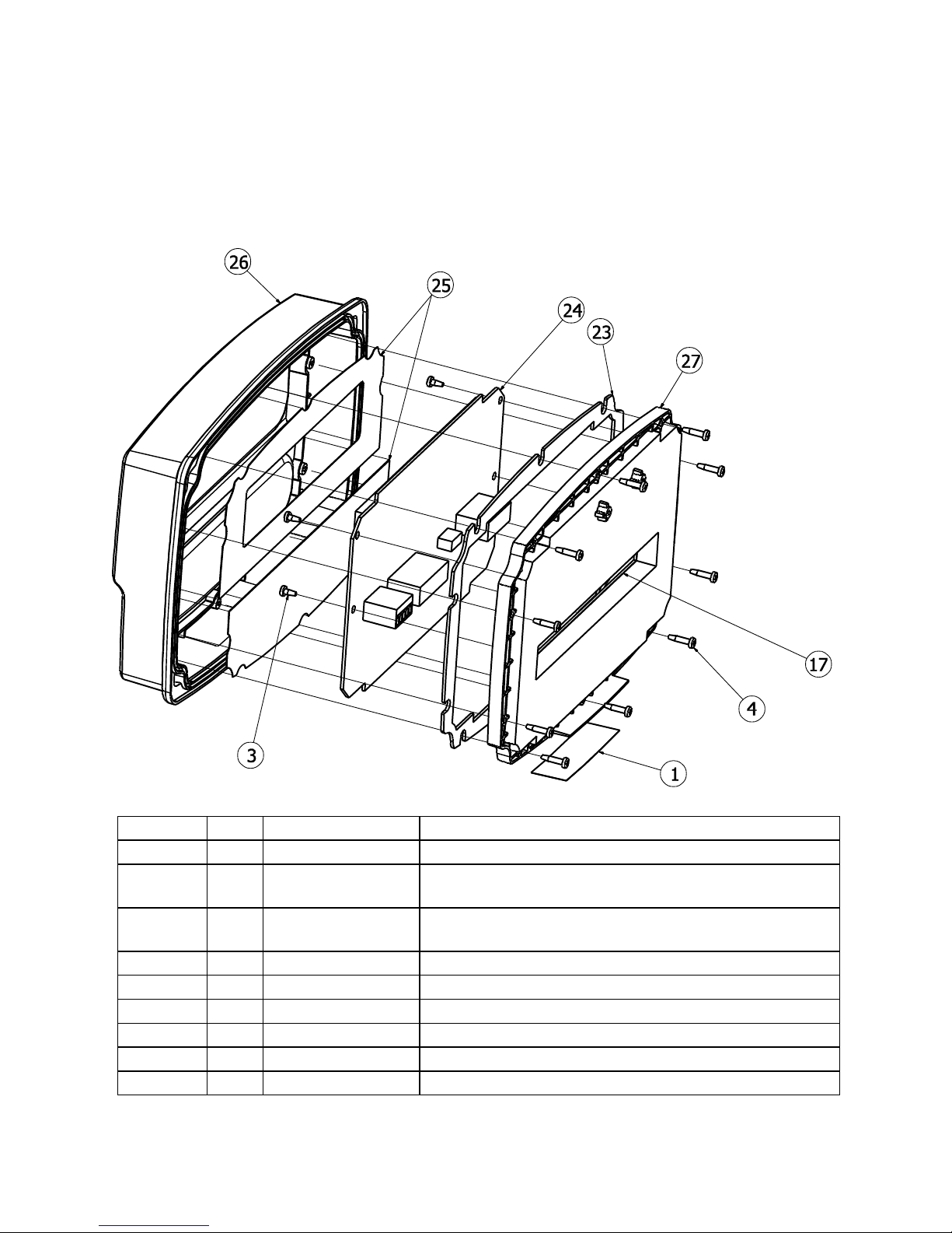
JAC190 Installation & Technical
Page 90
ITEM NO.
QTY.
PART NUMBER
DESCRIPTION
1 1 593GR986
SERIAL TAG ASSY
3 8 6021-1286
SCW PAN-HEAD PLASTIC THD. ROLLING, #4x1/4,
PHIL. DR. Z-PLATE
4
10
6021-1287
SCW PAN-HEAD PLASTIC THD. ROLLING, #4x1/2,
PHIL. DR. Z-PLATE
17
1
8400-B014-08
CONNECTOR GASKET, JAC190
23
1
8400-C013-08
CENTER GASKET, JAC190
24
1
8400-D003-0A
PCB ASSY JAC190 CONTROLLER
25
1
8400-D008-08
JAC190 OVERLAY
26
1
8400-D010-08
PLASTIC FRONT, JAC190
27
1
8400-D011-08
PLASTIC CENTER, JAC190
13. PARTS IDENTIFICATION
13.1 Front Sub Assembly
8400-M022-O1 Rev A 02/11
Page 97
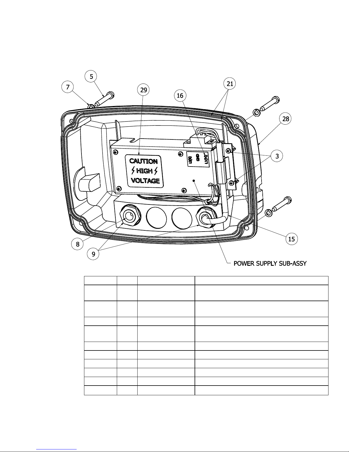
Page 91
13.2 Rear Sub Assembly
ITEM NO.
QTY.
PART NUMBER
DESCRIPTION
3 8 6021-1286
SCW PAN-HEAD PLASTIC THD. ROLLING,
#4x1/4, PHIL. DR. Z-PLATE
5 4 6021-1288
SCW FILLISTER MACHINE-SCW 10-32X1.5.
DL HOLE ONE WAY S.S.
7 4 6024-0037
WASHER LOCK HELICAL SP #10 REG SS
8 1 6540-1104
PLUG, HOLE 0.343” X 0.187” X 1” LG,
SILICONE RUBBER
9 2 6610-2248
CONN GLAND .187-.312 GRIP .599 MTG BLK
15 1 6980-1030
POWER CORD 18/3 SVT CEE 6.3 FT
16
1
8200-B104-08
LABEL: 205-210 TERM. BLOCK
21
2
8400-B020-08
O-RING, JAC190
28
1
8400-D012-08
PLASTIC BACK, JAC190
29
1
8510-C346-0I
LABEL CAUTION HIGH VOLTAGE
JAC190 Installation & Technical
8400-M022-O1 Rev A 02/11
Page 98
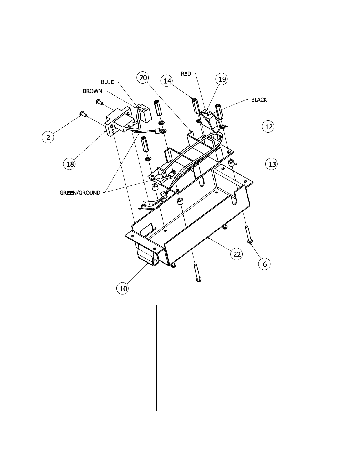
JAC190 Installation & Technical
Page 92
ITEM NO.
QTY.
PART NUMBER
DESCRIPTION
2 2 6021-0423
SCW PAN-HEAD.. MACHINE-SCW 04-40X.250
6 4 6021-2018
SCW PAN-HEAD.. MACHINE-SCW 04-40X.875
10 1 6610-5007
CABLE CLIP, 1” X 1” GREY
12 4 6680-0026
WASHER LOCK INT TOOTH # TYPE A Z-PL
13 4 6680-0138
SPACER #6 X .187 NYLON
14 4 6680-1107
SPACER #4-40X.750 3/16 HEX ALU. Z/P
18
1
8400-B017-0A
190 AC POWER CABLE
(See Section 12.4 AC Wiring Detail)
19
1
8400-B018-0A
DC POWER CABLE, JAC190
20
1
8400-B019-08
POWER SUPPLY, JAC190
22
1
8400-C005-08
POWER SUPPLY COVER, JAC190
13.3 Power Supply Sub Assembly
8400-M022-O1 Rev A 02/11
Page 99
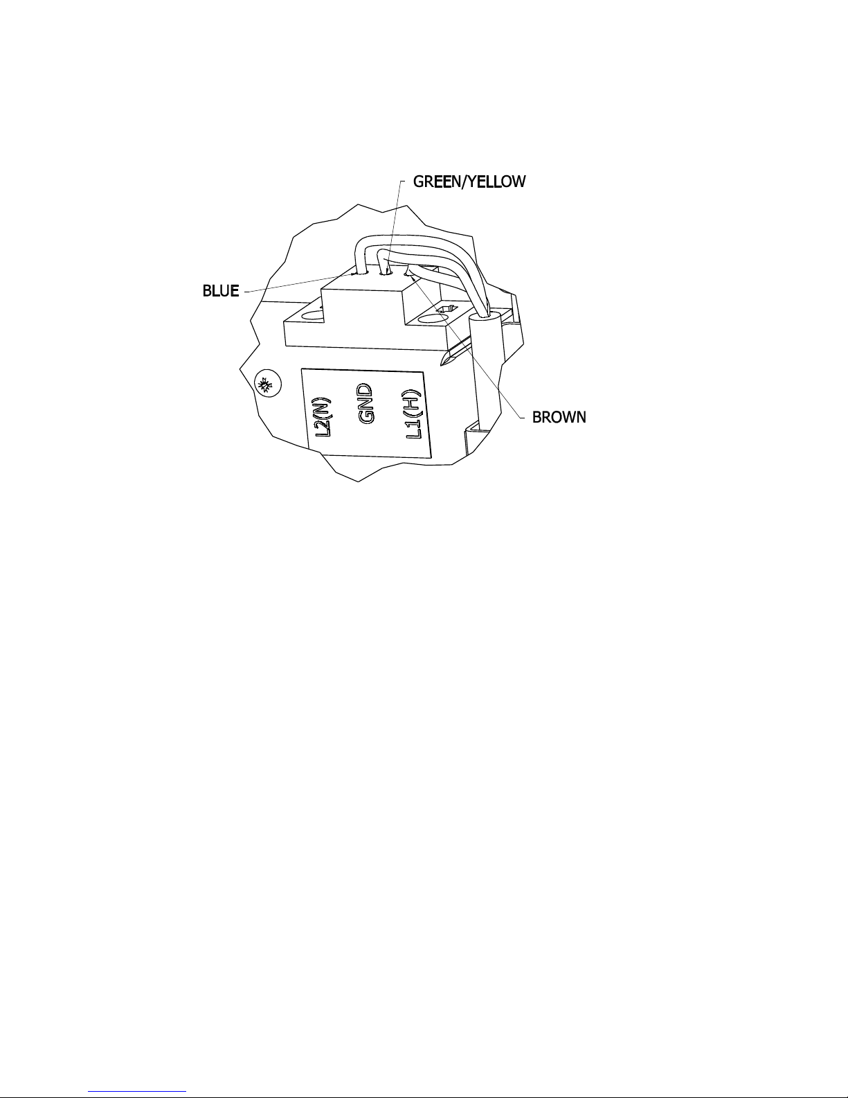
Page 93
13.4 AC Wiring Detail
JAC190 Installation & Technical
8400-M022-O1 Rev A 02/11
 Loading...