

Page 1

ST 90 Oil Burner
Installation & Maintenance
Manual
Page 2

178 045 19
Page 3

Thank you for choosing a Nu-way burner. As you would expect from a Company who
has a pedigree of more than 75 years in the heating industry, our after sales service is
second to none.
Your relationship with Nu-way does not stop with the purchase of a burner. We have
a team of highly experienced Service Engineers who travel throughout the UK and
around the world, to service and react swiftly to breakdowns. Preventative
maintenance is clearly the most cost effective way of ensuring that the burner is
running at its most efficient, but also that business critical activities are not interupted
with potentially costly breakdowns. A Nu-way Service contract is a cost effective way
of ensuring the correct and most efficient output and reliability from your Nu-way
burner is maintained at all times.
Nu-way Spares Department carry more than four thousand spares, all of which are
available from stock at competitive prices. Nu-way has the largest range of
commercial spares available to the market. Our Spares sales team collectively have
more than 170 years employment with Nu-way and are therefore more than
experienced in offering advice and practical backup, by ensuring the correct part is
identified and despatched in a timely manner.
In addition to these departments we also offer a dedicated technical helpline which is
manned during office hours. (Please note this is a premium rate line)
The Nu-way promise is that your investment in a Nu-way burner is fully supported
throughout the life of the product.
Please call us to discuss how we can ensure you benefit from the many services we
have to offer.
Burner Sales: 01905 791640
Service: 01905 791680
Spares: 01905 791650
Technical Helpline:
Page 4
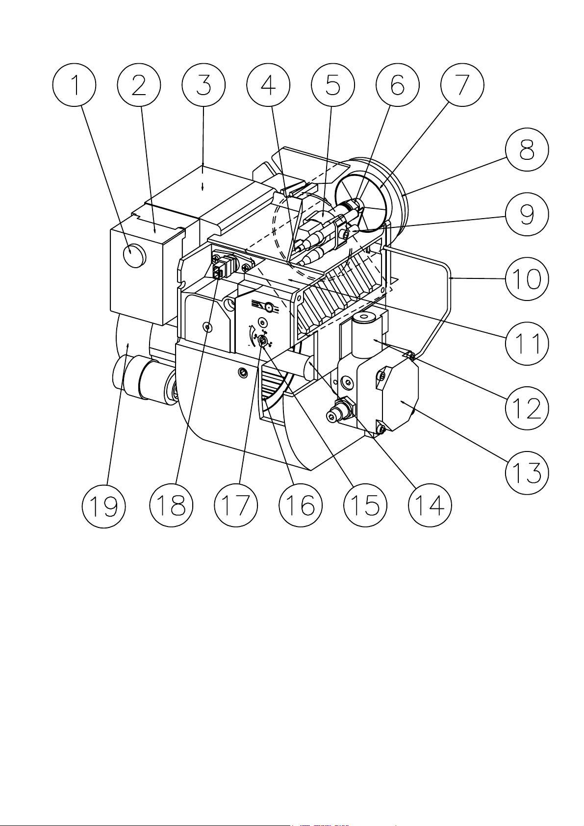
DESCRIPTION
COMPONENTS
1. Reset button
2. Control box
3. Ignition transformer
4. Ignition cables
5. Nozzle assembly
6. Nozzle
7. Brake plate
8. Blast tube
9. Ignition electrodes
10. Connecting pipe
11. Air damper
12. Solenoid valve
13. Pump
14. Drive coupling
15. Indication, air damper
16. Fan wheel
17. Adjustment, air damper
18. Photoresistor
19. Motor
171 205 32 96-01
Page 5
Page 6
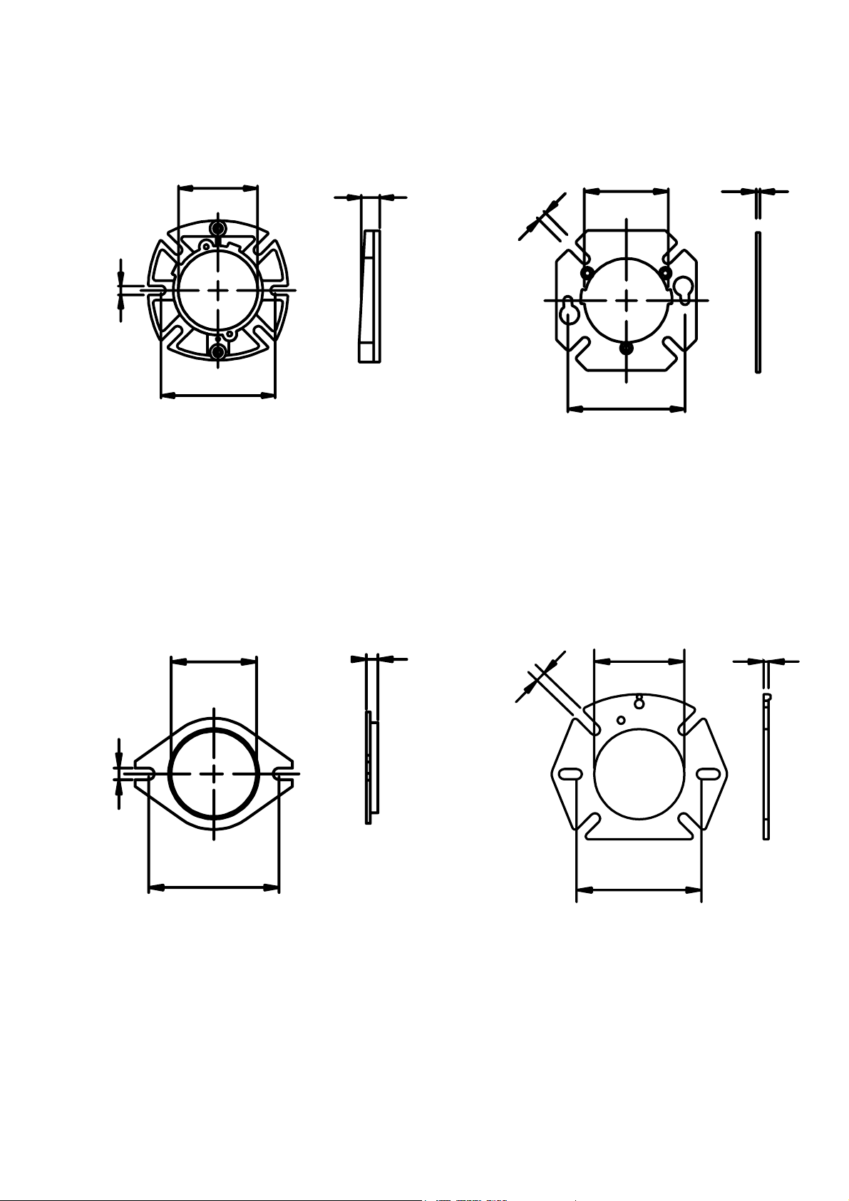
TECHNICAL DATA
DIMENSIONS
Flange A
10,3
ø89,7
130-150
25
Flange C
10
ø90
125
4
Flange B
12
ø89,5
136-150
12
Flange D
10,3
ø90
125-150
5
171 215 76 99-01
Page 7
GENERAL INSTRUCTIONS
GENERAL RULES
The installation of an oil burner should
be carried out in accordance with local
regulations. The installer of the burner
must therefore be aware of all
regulations relating to oil and combustion.
Only oil suitable for the burner should
be used and then in combination with
a suitable oil filter before the oil pump
of the burner.
If the burner is replacing an existing
burner make sure that the oil filter is
replaced or cleaned. The installation
must only be undertaken by experienced personnel.
INSTALLATION INSTRUCTIONS
General installation instructions accompany the burner and should be left
in a prominent place adjacent to the
burner.
ADJUSTMENT OF BURNER
The burner is from the factory pre-set to
an average value that must then be
adjusted to the boiler in question.
All burner adjustments must be made
in accordance with boiler manufacturers
instructions.These must include the
checking of flue gas temperatures,
average water temperature and CO2 or
O2 concentration.
To adjust the combustion device, start
by increasing the air volume somewhat.
When the burner starts it is burning
with excess air and smoke number 0.
Reduce the air volume until soot occurs
and increase again to reach a
combustion free of soot.
By this procedure an optimum adjustment is obtained. If larger nozzles are
used the preadjustment of the air volume
must be increased.
Increase the oil quantity
Raise the flue gas temperature by
removing turbulators, if any, in the
boiler
.
INSTRUCTIONS FOR USE
The end user of the burner should be
instructed about the operation and
safety features of the burner.
He should also be made aware of the
importance of the area around the boiler/
burner being kept free of combustible
material.
PUMP ADJUSTMENT
See separate description.
ADJUSTMENT OF BURNER
To obtain a correct adjustment a flue
gas analysis and a temperature
measurement must be carried out.
Otherwise there is a risk that a bad
adjustment may cause a formation of
soot, bad efficiency or condensate in
the chimney.
MAINTENANCE
The boiler/burner should be examined
regularly for any signs of malfunction
or oil leakage.
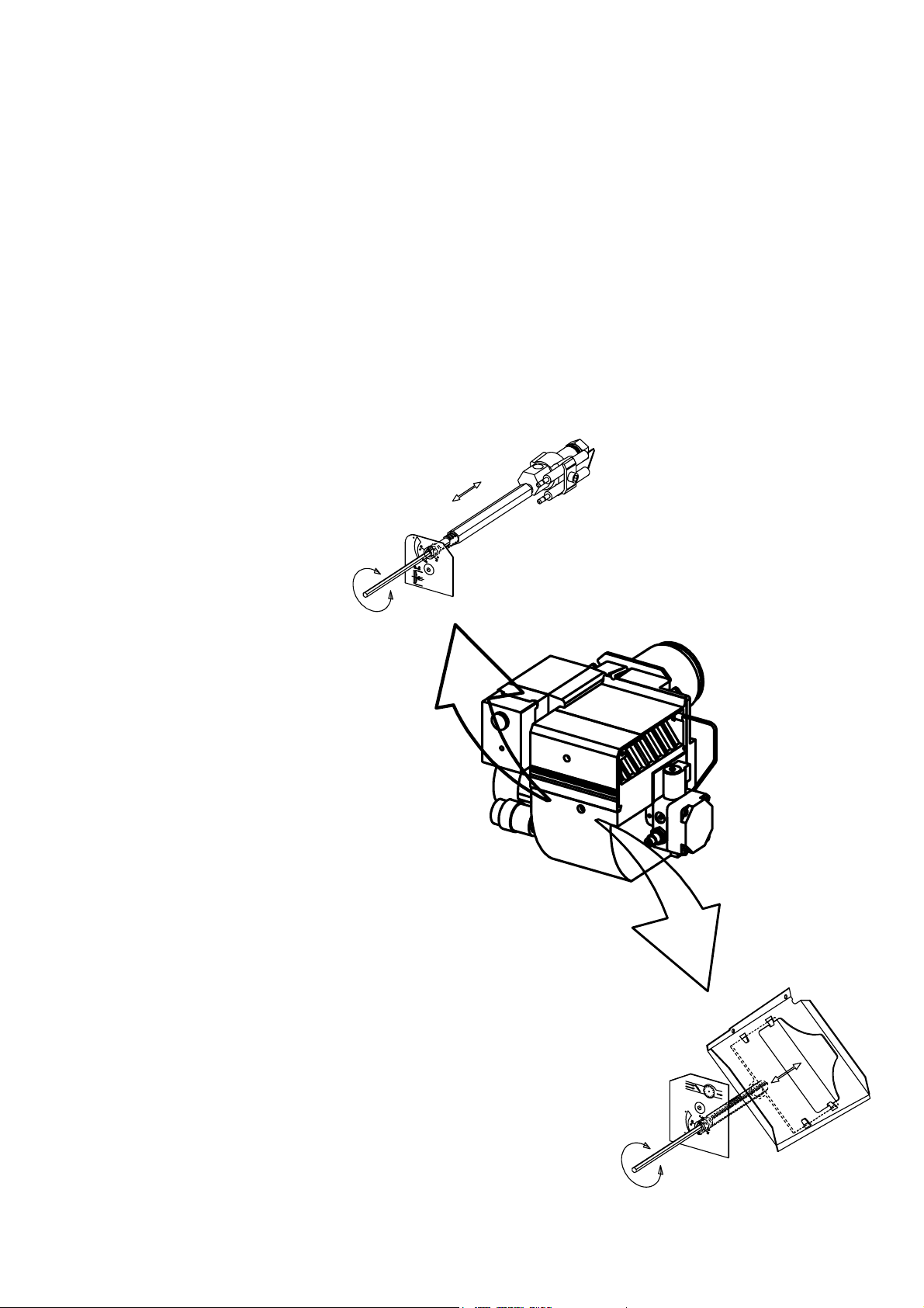
ADJUSTMENT OF NOZZLE
ASSEMBLY 0 - 22
CONDENSATION IN CHIMNEY
A modern burner works with less excess air and often also with smaller
nozzles than older models. This
increases the efficiency but also the
risk of condensation in the chimney.
The risk increases if the area of the
chimney flue is too large. The temperature of the flue gases should exceed
60°C measured 0,5 metres from the
chimney top.
Measures to raise the temperature:
Insulate the chimney in cold attics
Install a tube in the chimney
Install a draught regulator (dilutes the
flue gases during operation and dries
them up during standstill)
AIR ADJUSTMENT 0 - 32
171 305 69 97-01
Page 8
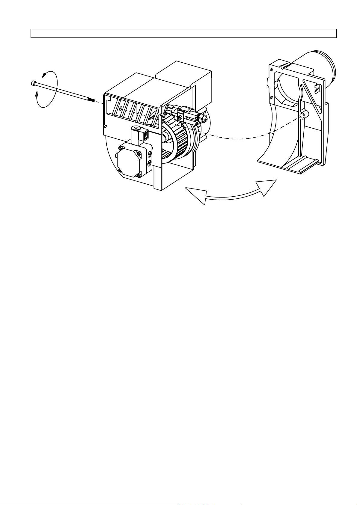
MAINTENANCE OF OIL BURNER
Warning: Before doing any service switch off power at the main switch and cut off the oil supply.
SERVICE OF BURNER HEAD AND
NOZZLE ASSEMBLY
171 305 68 94-01
Page 9
Page 10
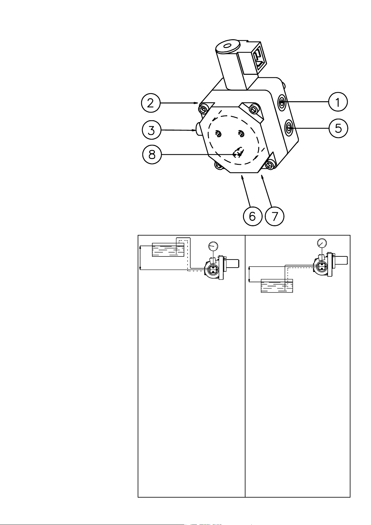
INSTRUCTIONS PUMP TYPE DANFOSS BFP11
TECHNICAL DATA
Viscosity range: 1,3-12,0 mm2/s
Pressure range: 7-15 bar
Oil temperature: -10 to +70°C
COMPONENTS
1. Nozzle port R 1/8"
2. Pressure gauge port
3. Pressure adjustment, 4mm allen key
5. Vacuum gauge port R 1/8"
6. Return line R 1/4"
7. Suction line R 1/4"
8. Return plug
SUCTION LINE TABLES
The suction line tables consist of
theoretically calculated values where
the pipe dimensions and oil velocity
have been matched so that turbulences
will not occur. Such turbulences will
result in increased pressure losses and
in acoustic noise in the pipe system. In
addition to drawn copper piping a pipe
system usually comprises 4 elbows, a
non-return valve, a cut-off valve and an
external oil filter.
The sum of these individual resistances
is so insignificant that they can be
disregarded. The tables do not include
any lengths exceeding 100 m as
experience shows that longer lengths
are not needed.
The tables apply to a standard fuel oil of
normal commercial quality according to
current standards. On commissioning
with an empty tube system the oil pump
should not be run without oil for more
than 5 min. (a condition is that the pump
is being lubricated during operation).
The tables state the total suction line
length in metres at a nozzle capacity of
2,5 kg/h. Max. permissible pressure at
the suction and pressure side is 2,0 bar.
PURGING
On 1-pipe systems it is necessary to
purge the pump. On 2-pipe systems
purging is automatic through the return
line.
H
H
1-pipe system 1-pipe system
Height Pipe diameter
H ø4 mm ø5 mm ø6 mm
mmmm
4,0 51 100 100
3,5 45 100 100
3,0 38 94 100
2,5 32 78 100
2,0 26 62 100
1,5 19 47 97
1,0 13 31 65
0,5 6 16 32
Two-pipe system
Height Pipe diameter
H ø6 mm ø8 mm ø10 mm
mmmm
4,0 33 100 100
3,5 31 98 100
3,0 29 91 100
2,5 27 85 100
2,0 25 79 100
1,5 23 72 100
1,0 21 66 100
0,5 19 60 92
Height Pipe diameter
H ø4 mm ø5 mm ø6 mm
mmmm
With an underlying tank a 1-pipesystem is not recommended
Two-pipe system
Height Pipe diameter
H ø6 mm ø8 mm ø10 mm
mmmm
0 17 53 100
-0,5 15 47 100
-1,0 13 41 99
-1,5 11 34 84
-2,0 9 28 68
-2,5 7 22 53
-3,0 5 15 37
-3,5 3 9 22
4,0 1 3 6
171 505 28 96-01
Page 11
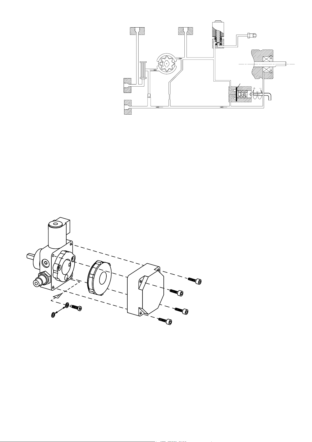
FUNCTION DANFOSS BFP11
When the oil pump is started, oil is
drawn from the suction connection (S)
through the filter (H) to the suction side
of the gear wheel (C).
V
P1
NC
E
The gear wheel then pumps oil to the
pressure side and the oil is put under
H
pressure.
The pressure is controlled and kept
constant at the set value by the regulating
valve (P1) with the diaphragm (D).
The regulating valve (P1) distributes the
oil quantity supplied by the gear set (C)
between the nozzle port (E) and the
S
R
C
G
A
return side of the pump (R).
The oil quantity utilized is determined by
the set pressure on the regulating valve
(P1) and the size of the oil nozzle in the
nozzle line.
The valve (P1) functions in the following
way:
- When the opening pressure has been
reached, the passage to the return
side opens.
- The diaphragm and the spring keep
the pump pressure constant at set
value.
- If the pump is overloaded, i.e. if you
try to get out more oil than the gear
set can supply under existing circumstances, the oil pressure falls below
the set value and the valve closes
REPLACEMENT OF CARTRIDGE FILTER, MOUNTING/DISMOUNTING
RETURN PLUG
D
P
1
against the return side (R) by means
of the diaphragm (D) and goes into
starting position.
This can be remedied by:
- Reducing the pump pressure.
- Reducing the oil quantity supplied
by using a smaller nozzle.
- Using a pump with a larger capacity.
In case of one-pipe operation the horseshoe-shaped washer will be mounted
under the screw head, and in case of
two-pipe operation, the horse-shoeshaped washer will be removed.
The horse-shoe-shaped washer will be
introduced in all BFP 11-pumps .
To minimize the leak between cover
plate and pump housing when running
one-pipe operation, the changeover
screw will be mounted generally. But
in order for the return oil in the pump to
be able to flow freely to the suction
side, a horse-shoe-shaped washer will
be mounted under the screw.
171 505 29 00-01
Page 12

NOZZLE TABLE
Gph 8 9 10 11 12 13 14 15
kg/h kW Mcal/h kg/h kW Mcal/h kg/h kW Mcal/h kg/h kW Mcal/h kg/h kW Mcal/h kg/h kW Mcal/h kg/h kW Mcal/h kg/h kW Mcal/h
0,40 1,33 16 13 1,41 17 14 1,49 18 15 1,56 18 16 1,63 19 17 1,70 20 17 1,76 21 18 1,82 21 18
0,50 1,66 20 17 1,76 21 18 1,86 22 19 1,95 23 20 2,04 24 21 2,12 25 22 2,20 26 22 2,28 27 23
0,60 2,00 24 20 2,12 25 22 2,23 26 23 2,34 28 24 2,45 29 25 2,55 30 26 2,64 31 27 2,73 32 28
0,65 2,16 26 22 2,29 27 23 2,42 29 25 2,54 30 26 2,65 31 27 2,75 33 28 2,86 34 29 2,96 35 30
0,75 2,49 29 25 2,65 31 27 2,79 33 28 2,93 35 30 3,08 36 31 3,18 38 32 3,30 39 34 3,42 40 35
0,85 2,83 33 29 3,00 36 31 3,16 37 32 3,32 39 34 3,47 41 35 3,61 43 37 3,74 44 38 3,87 46 39
1,00 3,33 39 34 3,53 42 36 3,72 44 38 3,90 46 40 4,08 48 42 4,24 50 43 4,40 52 45 4,56 54 46
1,10 3,66 43 37 3,88 46 39 4,09 48 42 4,29 51 44 4,48 53 46 4,67 55 48 4,84 57 49 5,01 59 51
1,20 3,99 47 41 4,24 50 43 4,47 53 46 4,68 55 48 4,89 58 50 5,09 60 52 5,29 63 54 5,47 65 56
1,25 4,16 49 42 4,40 52 45 4,65 55 47 4,88 58 50 5,10 60 52 5,30 63 54 5,51 65 56 5,70 68 58
1,35 4,49 53 46 4,76 56 48 5,02 59 51 5,27 62 54 5,50 65 56 5,73 68 58 5,95 70 61 6,15 73 63
1,50 4,98 59 51 5,29 63 54 5,58 66 57 5,85 69 60 6,11 72 62 6,36 75 65 6,60 78 67 6,83 81 70
1,65 5,49 65 56 5,82 69 59 6,14 73 63 6,44 76 66 6,73 80 69 7,00 83 71 7,27 86 74 7,52 89 77
1,75 5,82 69 59 6,18 73 63 6,51 77 66 6,83 81 70 7,14 85 73 7,42 88 76 7,71 91 79 7,97 94 81
2,00 6,65 79 68 7,06 84 72 7,45 88 76 7,81 93 80 8,18 97 83 8,49 101 86 8,81 104 90 9,12 108 93
2,25 7,49 89 76 7,94 94 81 8,38 99 85 8,78 104 89 9,18 109 94 9,55 113 97 9,91 117 101 10,26 122 105
2,50 8,32 99 85 8,82 105 90 9,31 110 95 9,76 116 99 10,19 121 104 10,61 126 108 11,01 130 112 11,39 135 116
2,75 9,15 108 93 9,71 115 99 10,24 121 104 10,73 127 109 11,21 133 114 11,67 138 119 12,11 144 123 12,53 148 128
3,00 9,98 118 102 10,59 126 108 11,16 132 114 11,71 139 119 12,23 145 125 12,73 151 130 13,21 157 135 13,67 162 139
3,50 11,65 138 119 12,35 146 126 13,03 154 133 13,66 162 139 14,27 169 145 14,85 176 151 15,42 183 157 15,95 189 163
4,00 13,31 158 136 14,12 167 144 14,89 176 152 15,62 185 159 16,31 193 166 16,97 201 173 17,62 209 180 18,23 216 186
4,50 14,97 177 153 15,88 188 162 16,75 198 171 17,57 208 179 18,35 217 187 19,10 226 195 19,82 235 202 20,51 243 209
5,00 16,64 197 170 17,65 209 180 18,62 221 190 19,52 231 199 20,39 242 208 21,22 251 216 22,03 261 225 22,79 270 232
5,50 18,30 217 187 19,42 230 198 20,48 243 209 21,47 255 219 22,43 266 229 23,34 277 238 24,23 287 247 25,07 297 256
6,00 19,97 237 204 21,18 251 216 22,34 265 228 23,42 278 239 24,47 290 249 25,46 302 260 26,43 313 269 27,49 326 280
6,50 21,63 256 220 22,94 272 234 24,20 287 247 25,37 301 259 26,51 314 270 27,58 327 281 28,63 339 292 29,63 351 302
7,00 23,29 276 237 24,71 293 252 26,06 309 266 27,33 324 279 28,55 338 291 29,70 352 303 30,84 366 314 31,91 378 325
7,50 24,96 296 254 26,47 314 270 27,92 331 285 29,28 347 298 30,59 363 312 31,83 377 324 33,04 392 337 34,19 405 349
8,00 26,62 316 271 28,24 335 288 29,79 353 304 31,23 370 318 32,63 387 333 33,95 403 346 35,25 418 359 36,47 432 372
8,50 28,28 335 288 30,00 356 306 31,65 375 323 33,18 393 338 34,66 411 353 36,07 428 368 37,45 444 382 38,74 459 395
9,00 29,95 355 305 31,77 377 324 33,59 398 342 35,14 417 358 36,71 435 374 38,19 453 389 39,65 470 404 41,02 486 418
The table applies to oil with a viscosity of 4,4 mm2/s (cSt) with density 830 kg/m3.
Pump pressure bar
BURNER WITH PREHEATER
Consider that on preheating the oil quantity is reduced by 5-20% depending on.
- Rise in temperature at the nozzle
- Design of nozzle
- Capacity (high capacity - small difference)
171 505 44 00-01
Page 13
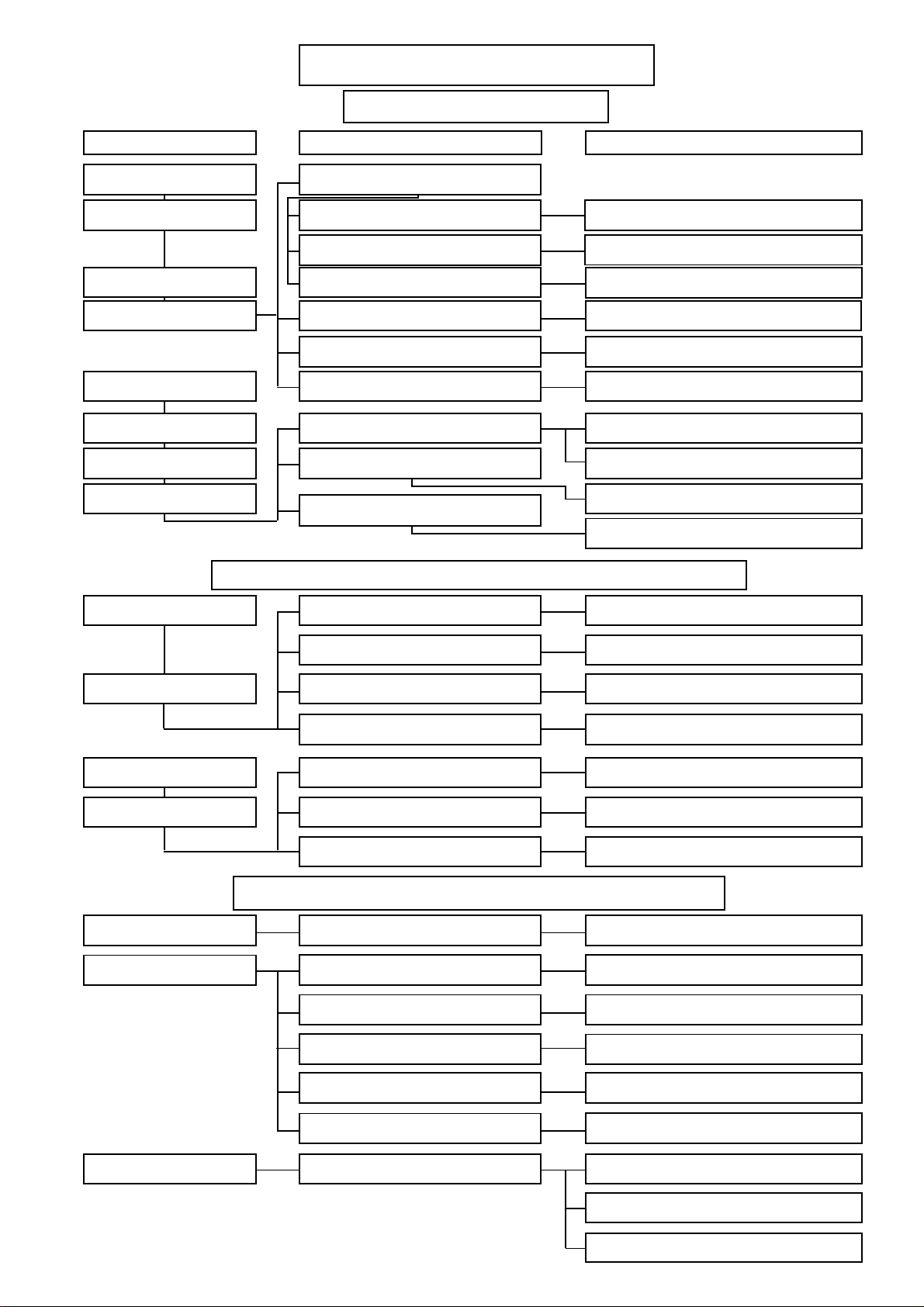
FAULT LOCATION
BURNER FAILS TO START
Situation
Motor runs Flame instabillity
Burner pre-purges
Flame occurs
Burner locks out
Motor runs
Burner pre-purges
No flame occurs
Burner locks out
Possible causes
Incorrect head settings
Low oil pressure
Excess air
Photocell not seeing light
Photocell failed
Control faulty
False light
No spark
No oil
BURNER FAILS TO START AFTER NORMAL OPERATION
Burner fails to start
Fuse has blown
Remedies
Check nozzle to burner head dimension and
electrode position
Check oil pressure
Adjust air damper
Check that photocell is clean and unobstructed
Confirm with new photocell
Confirm with new control. (NB. it is advisable to
change the photocell if also changing control)
Check that photocell is not seeing ambient light
Check that H.T. leads are sound and are not
arcing other than at electrode gap
Check oil supply to burner - check that pump
is not airlocked
Check operation of magnetic valve
Check or replace fuse if necessary. Check
reason for failure
Lamp not lit
Motor runs
Burner runs to lockout
Burner pulsates on start-up
only with hot flue
Burner pulsates on start-up
Appliance thermostat has not reset
Appliance overheat device has operated
Control relay or photocell defective
No oil being delivered
Excessive flue draught is preventing
flame establishment
No spark
Reset overheat device. Find reason for its
Check that tank, oil lines, fire valve, pump and
Check ignition transformer. Check electrode
Adjust thermostat
operation and rectify
Check by replacement
nozzle are all in good order
Rectify condition
gap and porecelains
DELAYED IGNITION, BURNERS STARTS VIOLENTLY
Excessive draught
Nozzle partly blocked
Oil pressure too low
Flue blocked or damaged
Fan slipping on shaft
Recommission burner
Replace nozzle
Check and recommission
Check and rectify
Check and retighten
Burner starts violently
171 915 01 01-01
Pump coupling loose or worn
Delayed ignition
Check and replace
Check the electrode adjustment, see diagram
Check electrodes for damage
Check H.T. leads for damage and disconnection
Page 14

NOTES
Page 15

NOTES
Page 16

Enertech Limited, P O Box 1, Vines Lane
Droitwich, Worcestershire, WR9 8NA
tel: +44 (0) 1905 794331 • fax:+44 (0) 1905 794017
email: [email protected] • web: www.nu-way.co.uk
 Loading...