

Page 1

Installation & Maintenance Manual
Series SG fully automatic gas burners
Selectos SG100 & SG170
Gas Burner
11/12
Page 2

IMPORTANT - SAFETY
It is essential that the following
instructions and adjustments are
carried out by qualified engineers
that are experienced in forced
draught gas burner commissioning.
In the UK it is a legal requirement
that anyone working on gas
installation, as defined in the “Gas
Safety (Installation & Use)
Regulations 1998”, is CORGI
registered. The manufacturer
cannot be held responsible for any
consequential damage, loss or
personal injury as a result of failure
to follow these instructions, or as a
result of misuse.
SG10010603
Page 3
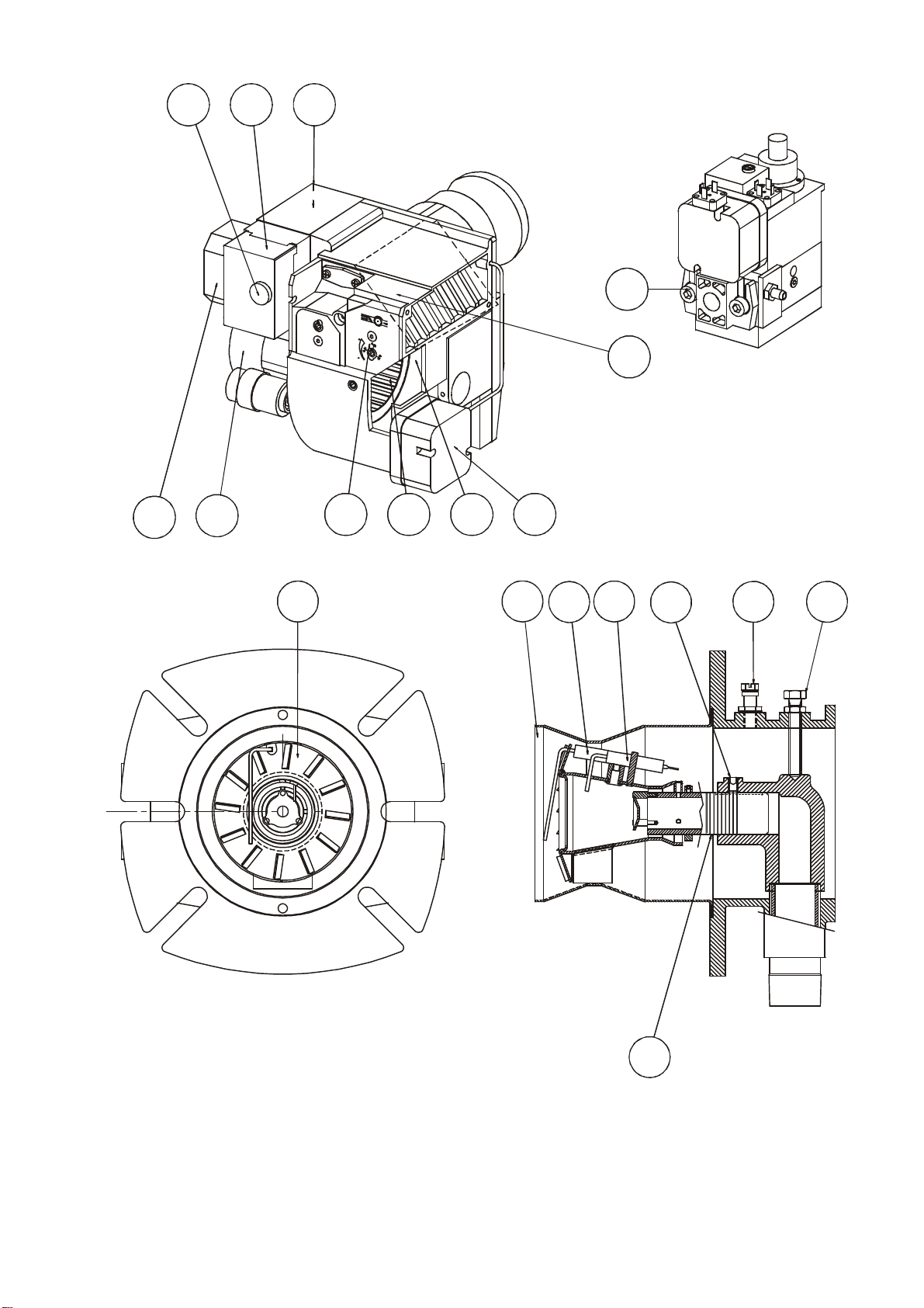
COMPONENT IDENTIFICATION
15171413121619184
321
5
11
10
9 7 6
8
COMPONENTS
1. Reset Button
2. Control Box
3. Transformer
4. MultiBlock
5. Air Damper
6. Air Pressure Switch
7. Fan Shield
8. Fan Wheel
9. Air Adjustment
10. Fan Motor
11. Electrical Connection
12. Flame Tube
13. Flame Probe
14. Ignition Electrode
15. Head Adjustment Screw
16. Pressure Test Point
17. Head Clamping Bolt
18. Adjustment Markings
19. Diffuser
SG10020602
Page 4
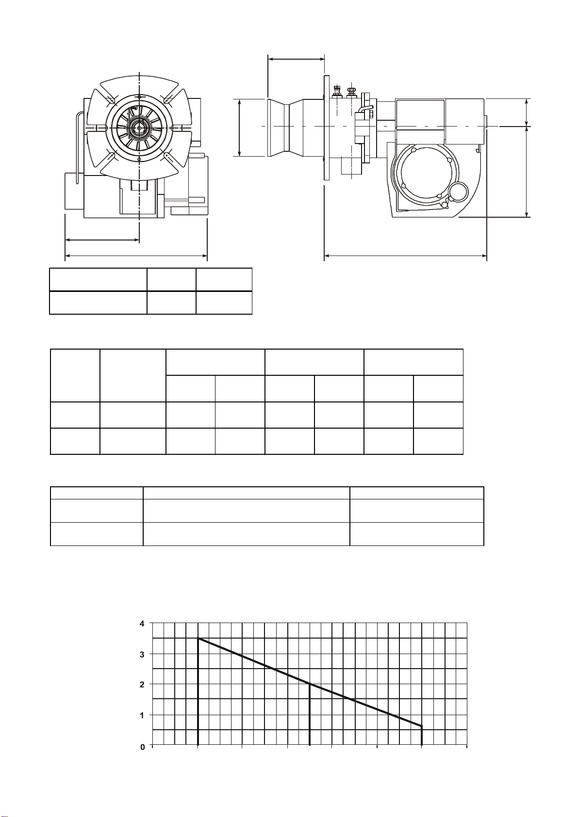
TECHNICAL DATA
323
192
6
0
113
114
180
Chamber
MODELS SG100/170
DIMENSIONS
139
275
Type SG100 SG170
Gas Connection **
1/2" BSP 3/4" BSP
The above dimensions are maximum measurements. Depending on the components used these may vary.
OUTPUT RANGE
Type Volume (m³) Min Volume (m³) Max Supply Pressure
SG100 60-110
SG170 110-160
Gross Input
(kW) *
(mbar)
NG LPG NG LPG NG LPG
5.6 2.3 10.3 4.2 20 37
10.3 4.2 15.0 6.2 20 37
ELECTRICAL DATA
Type Motor Ignition Transformer
SG100 125W, 2800rpm, 230v, 50Hz, 0.65A Electronic 230/11000V
SG170 125W, 2800rpm, 230v, 50Hz, 0.65A Electronic 230/11000V
* Calorific value:
Natural gas 10.7kW/m
LPG 26kW/m
3
** Depending on gas type and
available pressure
PERFORMANCE ENVELOPE
3
SG100
Resistance (mbar)
40 60 80 100 120 140 160
SG170
Burner Output (kW)
SG10030603
Page 5
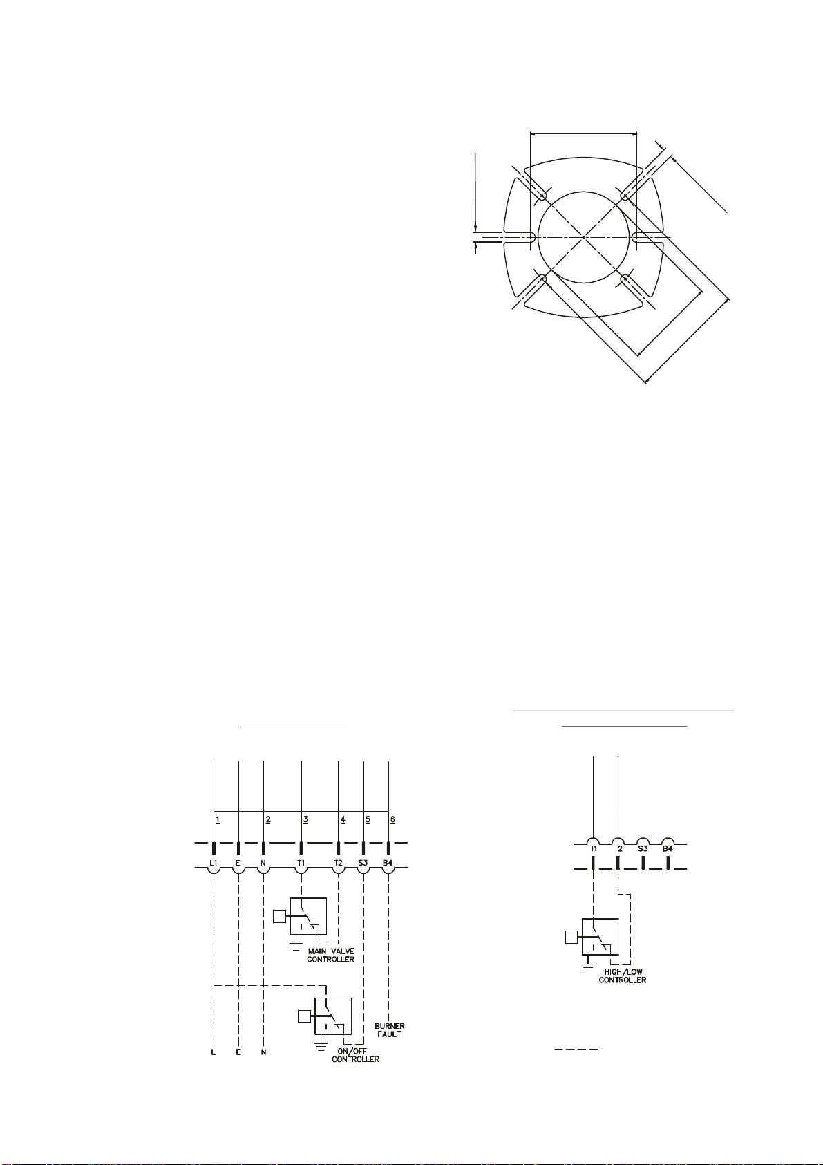
140-190
13.0m
m
1
2.0mm4 PLACES
MOUNTING THE BURNER
EXTERNAL WIRING
ADDITIONAL CONNECTIONS FOR
If the hinged extension/flame tube assembly is not fitted to
the fan case assembly, it should be fitted before mounting to
the application using the pins provided. Ensure that the gas
inlet connection is at the bottom.
Once the burner is mounted open the hinged extension,
connect the flame probe and ignition cables. The terminal
ends are dissimilar and cannot be wrongly connected.
The gas train can now be fitted to the hinged extension.
• Ensure that the gaskets are seated correctly when
tightening the assembly.
• If the burner is to be fitted to a new packaged unit, refer
to the manufacturers recommendations.
• If the burner is to be used with an existing appliance
prepare the mounting flange.
• Ensure the joint between appliance and burner is
effectively sealed with the gasket provided.
2 PLACES
MOUNTING FLANGE DETAIL
a
i
D
D
C
0
P
2
1
0
1
2
-
5
5
1
ELECTRICAL
ELECTRICAL POWER SUPPLY
Connect a single phase 50Hz electrical supply to the burner observing all applicable IEE Regulations. Refer to the
connection diagram below or the wiring diagram contained in the instruction pack supplied with the burner.
ELECTRICAL CONNECTIONS
HIGH/LOW VALVES
7 PIN BLACK/BROWN
WIELAND PLUG
ON/OFF VALVES
4 PIN BROWN
WIELAND PLUG
SG10040602
Page 6
GENERAL INSTRUCTIONS
Burner Output (kW)
Head Settin
g
Chamber
SG170
The SG100 & 170 burners are
supplied for On/Off or High/Low
operation and for use with single
phase electrical supply. Where an
instruction or information is
applicable to only one of the burner
types, single or two stage, then this
is indicated in the text.
This manual is structured to enable
the user to proceed from the delivery
of the burner to its commissioning
and use.
The conditions to be fulfilled and the
controls and adjustments to be used
are dealt with in the sequence that
should be followed for the correct
assembly installation and use.
Commissioning procedures are
described and the location of
necessary controls and adjustments
to undertake these runs are
illustrated and supported by
appropriate tabular matter and
graphs.
Routine Maintenance and Fault
Finding complete the manual;
literature on proprietary components
is available on request.
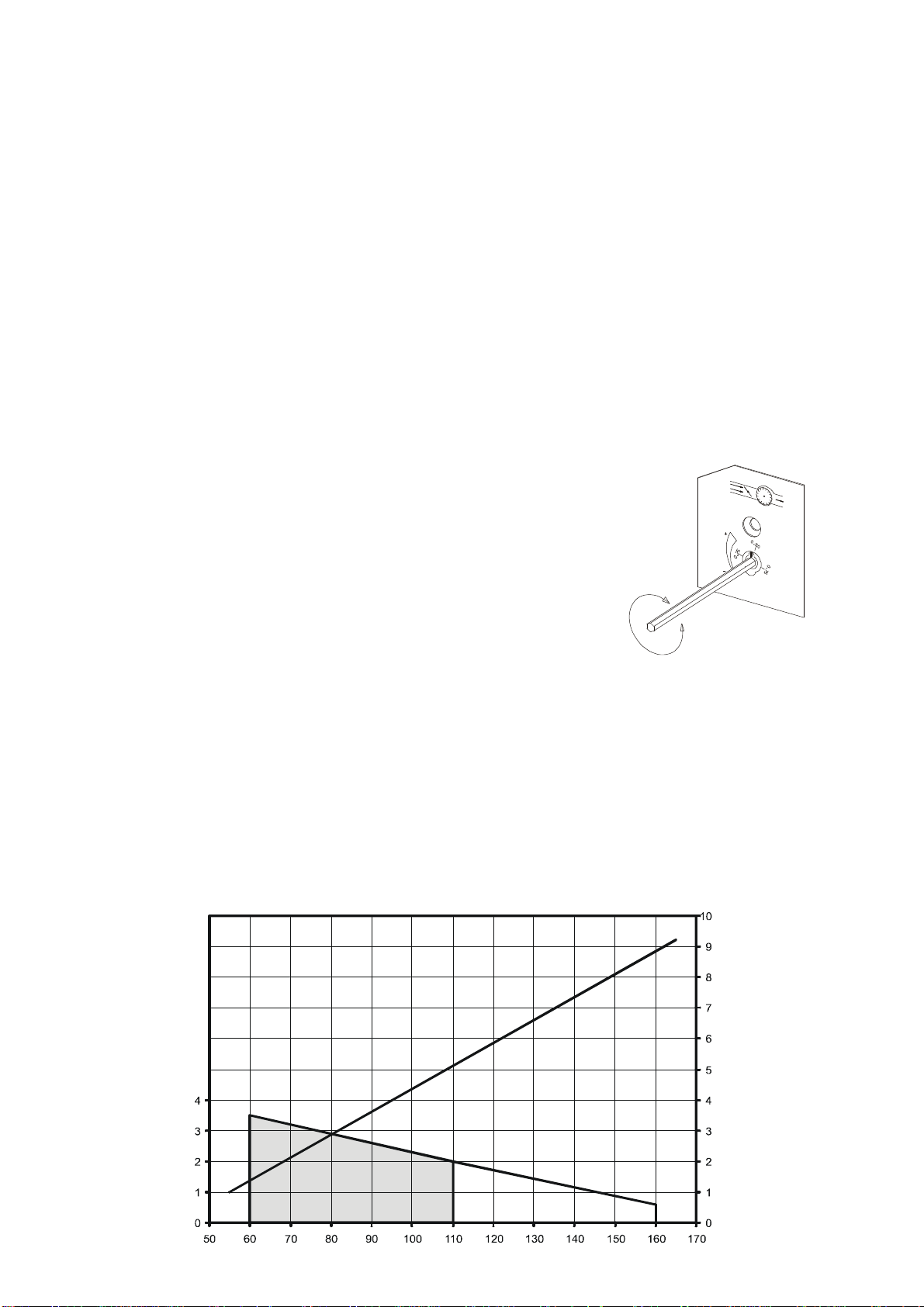
SETTING COMBUSTION HEAD
The venturi flame ring assembly is
adjustable longitudinally so that the
restriction between the air diffuser
and the throat of the flame tube
effectively meters the combustion air
and therefore the assembly should
be set to approximately the position
corresponding to the required gas
rate.
Method of Adjustment
Undo the two safety bolts of the
hinged extension.
Remove one hinge pin on the
opposite side to that which it is
required to swing the burner.
Unplug any electrical connections
that are restricting movement.
Swing the burner body away slowly,
at the same time unclipping the
ignition and flame detector leads.
Undo the lock nut clamping bolt.
Lift out the venturi flame ring
assembly.
Undo the socket set screw.
Adjust the position of the assembly
in the socket of the supporting elbow
aligning the required scribed ring
against the end of the socket.
The positon is relative to the firing
rate of the burner, the graph below
shows the relation between the head
setting and burner output.
Secure the assembly and replace in
reverse order taking care that the
assembly sits squarely on the gas
inlet spigot and is squarely locked
in position by its clamping bolt, and
that the burner is swung back into
position the ignition and flame
detector leads are carefully clipped
back on their respective electrodes
(the terminal ends are dissimilar so
that they cannot be wrongly
connected).
BURNER AIR CONTROLS
The air for combustion is controlled
by an adjustable air flap located
inside the air inlet on the right hand
side of the burner viewed from the
rear.
Its purpose is to regulate and control
the volume of combustion air flowing
through the burner.
On all burners the air adjustment can
be made with or without the cover
fitted with the use of an Allen key.
There is a visible scale to assist in
the setting of combustion air, it is
numbered between 1 and 22.
Final fine adjustment must be made
with the cover on.
Air Diffuser
The air diffuser is fitted to the front
end of the inner assembly and
located within the flame tube.
It controls the volume of combustion
air and creates a pressure drop over
the burner head to ensure good fuel/
air mixing and flame stability.
VENTURI HEAD SETTING
g
n
i
t
t
e
S
d
a
e
H
SG100
Resistance (mbar)
SG10050602
Page 7

GENERAL INSTRUCTIONS continued......
BURNER GAS CONTROLS
Low Gas Pressure Switch
The low gas pressure switch is
located on the inlet side of the gas
valve. It is required to monitor inlet
gas pressure during burner operation.
The low gas pressure switch is wired
in series with the appliance
controlling instruments and in the
event of gas pressure failure will
cause the burner to effect a safety
shut down.
Isolate the burner and remove the
gas pressure switch cover. Switch
on the electrical supply and allow the
burner to establish main flame. Slowly
turn the adjustment dial on the gas
pressure switch clockwise until the
flame is extinguished and the burner
shuts down. Turn the dial slowly
anticlockwise one division at a time
until the burner restarts and
establishes main flame. Recheck the
performance and then turn the dial a
further two divisions anticlockwise.
Switch off the burner and replace the
gas pressure switch cover.
Gas Valve Multibloc - Single
Stage (On/Off)
The gas valve is of the multibloc type
incorporating start rate, safety and
main valves and pressure governor.
Valve adjustments are detailed in the
Gas Controls and Adjustments
section.
Two Stage (High/Low)
The gas valve is of the multibloc type
incorporating start rate, safety and two
stage valve and pressure governor.
Valve adjustments are detailed in the
Gas Controls and Adjustment section.
FLAME MONITOR
Probe
The flame probe (flame rectification
probe) is located on the burner head
and is required to supervise the safe
operation of the burner under all
working conditions.
UV
As an option burners can be fitted
with an ultraviolet cell (UV) cell to
detect the presence of the flame.
BURNER OPERATING
SEQUENCE
Single Stage (On/Off) Burners
The operating sequence begins with
a pre-purge on full air, then start rate
gas flame which when proved allows
the burner to operate on main flame,
then to the “OFF” position after the
heat input is satisfied. The operation
is determined by demand of the
appliance control instruments.
Two Stage (High/Low) Burners
The sequence begins with an air prepurge on full air, followed by start rate
gas flame which when proved allows
the burner to operate on High/Low/
Off. The operation is determined by
the demand of the appliance control
instruments.
FLUE AND CHIMNEY
REQUIREMENTS
The top of the Chimney/Flue should
be above all roofs within a radius of
10 metres.
Check that it is suitable for use with
gas fired appliances. Reference
should be made to Local Authority
and other regulations governing such
installations.
Ensure that the flue pipe from the
appliance does not protrude into the
chimney beyond the wall thickness
and is sealed throughout its run.
If more than one appliance is
connected to a common flue/
chimney, ensure that the cross
section of the flue/chimney is
adequate for the total volume of flue
gases from all the appliances.
PLANT ROOM VENTILATION
An adequate supply of dust free,
fresh air is required for the burner at
both high and low level in accordance
with the appropriate standards.
GAS SUPPLY
The gas supply to the burner must
be constructed and installed to
comply with local conditions and
appropriate Codes and Standards. It
should be of sufficient size to satisfy
the pressure/volume requirements of
the burner to ensure its operation.
It is essential that a 90° manual shutoff is fitted upstream of the burner
gas train for the isolation of the burner
during servicing and maintenance.
The valve size must not be less than
the burner valve train or create
restriction to gas flow.
SG10060602
Page 8
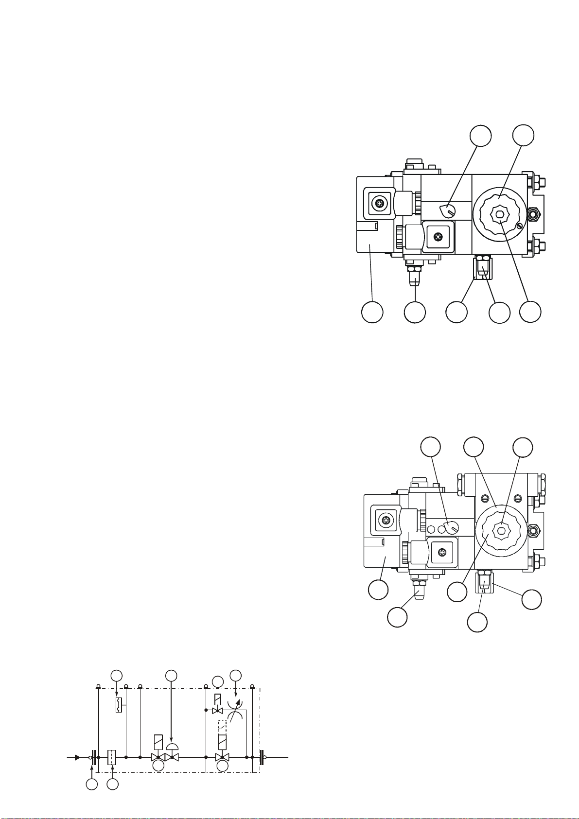
BURNER GAS CONTROLS & ADJUSTMENTS
Z)
SINGLE ST AGE (ON/OFF) USING PILOT GAS - MUL TIBLOC MB-DLE 405-412 B07
Includes gas pressure governor, safety , main and st art gas valves.
SINGLE ST AGE (ON/OFF) MAIN GAS IGNITION - MUL TIBLOC MB-DLE 405-412 B01
Contains gas pressure governor , safety , and main gas valves.
ADJUSTMENTS
A Governor adjustment (main and pilot). Turn clockwise to increase
pressure. Range 4-20 mbar.
B S tart gas rate (B07 valve only). T urn anticlockwise to increase
and clockwise to decrease rate.
C Main valve. Fast initial lift adjuster.
D Main gas adjustment. Slacken cheesehead screw, and turn the
fluted knob anticlockwise to open, clockwise to close.
E Low gas pressure switch (Optional).
F Upstream testpoint.
G Downstream testpoint.
TWO ST AGE (HIGH/LOW) USING PILOT GAS - MUL TBLOC MB-ZRDLE 405-412 B07
Includes gas pressure governor, safety, two position main and pilot valves.
TWO ST AGE (ON/OFF) USING MAIN GAS IGNITION - MUL TIBLOC MB-ZRDLE 405-412 B01
Includes gas pressure governor, safety, two main and start gas valves.
E
F
B
A
G
D
C
ADJUSTMENTS
A Governor adjustment for main flame. Turn clockwise to increase
pressure. Range 3 - 20 mbar.
B Start gas rate (B07 valve only). Turn anticlockwise to increase and
clockwise to decrease rate.
C Main valve - first and second stage - fast initial lift adjuster.
D High flame throughput adjustment. Slacken off locking screw, turn
anticlockwise to increase and clockwise to decrease rate.
E Low flame throughput adjustment, as in D.
F Low pressure gas switch (Optional).
G Upstream testpoint.
H Downstream testpoint.
GAS MULTIBLOCK SCHEMA TIC
1 3
V1
2
V3
V2
V1 - Valve 1
V2 - Valve 2 - Single Stage (MB-D) or Two S t age(MBV3 - Pilot Valve (B07 Only)
1 - Pressure Switch (Optional )
2 - Regulator
3 - Restrictor
4 - Filter
5 - Inlet connection
F
G
A
D
E
C
B
H
4
5
SG10070501
Page 9
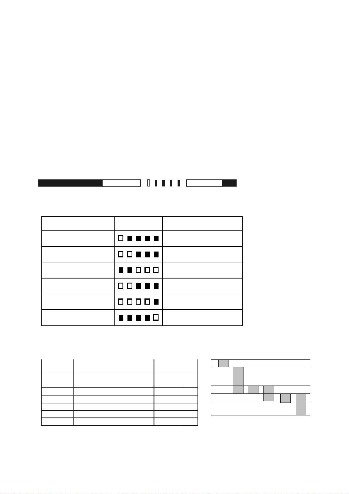
CONTROL BOX
illuminated phase dark phase Flash-Code dark phase
for 10 sec for 0.6 sec for 1.2 sec
tlw
tv1
tvz
tz ts
tv2
DMG970
INTRODUCTION
The burner control box DMG 970 controls and supervises forced draught burners for gas and dual fuel.
The microprocessor programming sequence ensures extremely stable timings independent of voltage variations,
ambient temperature and/or switch-on cycles. The built-in information system not only provides a continuous
monitoring of the actual state of the box (including monitoring of the start-up phase) but also informs about the
possible cause of a lockout. The lockout cause is stored in such a way that it can be retrieved even after a power
failure.
The control box is designed for maximum safety in case of fluctuations in the voltage supply. If the mains voltage
drops below the permitted level, operation is interrupted and the control box automatically prevents the start
sequence from being repeated. In this way, the safety of the system is not put at risk by a drop in the mains voltage.
This low-voltage protection works not only during start-up but also permanently during operation.
LOCK-OUT IDENTIFICATION
In the case of a failure the LED is permanently illuminated. Every 10 seconds the illumination is interrupted by a flash
code which indicates the cause of the error. The following sequence is performed and is then repeated as long as
the unit is not reset.
FLASH CODES
ERROR MESSAGE POSSIBLE FAULT
lock out safety time
stray light
air pressure s witch c losed
air press ure swit ch ti m eout air press ure swit ch does not
air press ure switc h opened
los s of flame
SEQUENCE TIMINGS
SEGMENT OPERATION
tlw
tv1 Supervised pr e- pur ge time 40
tvz Pre-ignition time 3
tz Ignitio n time total 5.5
ts Safety time 3
tv2 Delay 2nd-stage 12.5
Max. reaction time for air
proving switch
FL A SH CO DE
within lock out safety time no
flame es tabl i shm ent
stray l ight during startup
detec t or may be faulty
air pressure s witch c ont act
welded
cl ose within spec i fied tim e
air pressure s witch opened
during operation
los s of flame during operation
DURATION (S)
60
SG10080501
Page 10

PRE-COMMISSIONING CHECKS
The capacity of Selectos SG burners
using natural gas has been
determined at a minimum supply
pressure of 17.8mbar (max 40mbar).
For LPG the supply pressure should
be between 25mbar and 40mbar.
These burners will operate
satisfactorily on gas supply
pressures lower than those quoted
above, but burner capacity will be
reduced accordingly.
Any LPG high pressure regulator
fitted must be equiped with over
pressure shut off protection.
Turn off the gas supply at the manual
shut off valve upstream of the gas
valve inlet.
Fit an approved pressure measuring
instrument at the pressure test point
on the inlet of the gas MultiBloc. Turn
on the gas supply. Check gas
pressure, this will record static
pressure which will be higher than
running pressure, which should not
be less than 17.8mbar when running
on main flame.
INNER ASSEMBLY
Ensure that the ignition electrode
and ionisation probe are correctly
adjusted. Correct positioning is
shown on the Component
Identification page.
Ensure that the head has been
positioned according to the gas rate.
GAS TYPE
Ensure that the burner head is correct
for the type of gas to be used. Check
the burner data plate.
PURGING
The gas line is purged by loosening
the screw on the inlet pressure test
nipple. Connect a plastic hose and
conduct the gas into atmosphere.
After purging the gas line re-tighten
the screw.
LEAKAGE TESTING
When making a leak test of the gas
supply system the gas valve should
be closed. Connect a pressure gauge
to the test nipple on the gas valve.
The test pressure in the system
should be 1.5 x maximum inlet
pressure or minimum 150 mbar. If
there is any leakage, locate the
source by means of soapy water or a
leak detection spray. After tightening
repeat the test
DRY RUN
Turn off the electricity supply to the
burner. Close the manual gas shutoff valve.
To prevent the gas pressure (if fitted)
switch from locking out, remove the
cover and fit a temporary link.
Adjust the thermostats to call for
heat and switch on the electrical
supply to the burner, the pre-purging
period will begin (24-40 seconds). At
the end of this period the pre-ignition
period starts (3 seconds).
The gas valve is energized and opens
and the flame would be established.
At the end of the safety time (3 to 5
seconds) the control box will go to
lockout. The gas valve will be deenergised and the motor will stop
running. The dry run is complete.
Ensure to remove the link from the
gas pressure switch after the test is
finished.
IMPORTANT
After each adjustment, the gas flow rate and flue gas analysis should be checked.
ALWAYS
Use approved test equipment (Continually monitoring electronic equipment is recommended).
NEVER
Rely on a visual inspection of the flame as a guide to combustion quality.
SG10090501
Page 11

COMMISSIONING
Reference should be made to the
Burner Gas Controls and Adjustment
section of this manual for identification
and location of the following
adjustments.
None of these adjustments should
be made in isolation. One
adjustment will have an effect on
another. It is therefore essential that
the combustion quality and gas
throughput are monitored during the
commissioning procedure
PILOT BYPASS ADJUSTMENT
(B07 VALVE ONLY)
The bypass valve opens at the same
time as the first valve. Ignition gas
flow is set by using bypass restrictor.
Turn anticlockwise to increase and
clockwise to decrease rate.
If the governor pressure is set too low
there will be insufficient pressure for
the pilot bypass to operate.
MAIN GAS GOVERNOR
With a screwdriver turn the adjusting
screw to its minimum position then
turn back four complete revolutions.
This will give a reduced gas flow rate
to enable further adjustments to
commence.
Note: Should the burner lockout
when establishing start and main
flames then the probable cause is
air or inert gas in the gas line. This
can be removed by purging the line
through the pressure test points
located on the gas MultiBloc.
Alternatively, there may be
insufficient pressure on the gas
governor.
SETTING MAIN FLAME GAS RATE
Switch the burner on and allow it to
establish main flame.
Check the gas throughput with a gas
meter or with other approved
measuring instrument.
With a screwdriver slowly adjust the
gas governor to increase the gas
volume through the burner to the rate
required for the appliance.
Ensure that other appliances served
by the same meter are isolated when
gas throughputs are being adjusted.
With the gas flow rate for main flame
set and the burner running with stable
flame, the flue gases can now be
checked for CO2 and O2 with suitable
combustion testing instruments.
Figures of 9-10% CO2 and 3-5% O
2
are acceptable. For reasons of safety
the CO (carbon monoxide) should be
checked and should not exceed 100
ppm.
To achieve good combustion
efficiency or if the CO content is
exceeded, adjustments to the air and
gas settings can now be made while
the burner is running on main flame.
ADJUSTING THE MAIN VALVE
FAST INITIAL LIFT.
B01 VALVE - The adjuster acts as a
damper to the main valve, controlling
the rate of opening after initial lift. This
adjustment is used to reduce the
volume of gas that the valve passes
during the ignition safety phase.
Switch off and restart the burner.
Note the quality of the light up during
the ignition stage. If the light up is
weak, then increase the amount of
fast initial lift by turning the adjuster
anticlockwise. Turn the adjuster
clockwise if a heavy light up is
encountered. Repeat until a
satisfactory setting is achieved.
B07 VALVE - The adjuster acts to
control the rate of change between
high and low position. Turn the valve
clockwise to slow down the rate and
anticlockwise to increase the rate of
change.
SETTING LOW FLAME RATE
HIGH/LOW BURNER
(MB-ZRDLE VALVES ONLY)
Low flame gas rate is achieved by
adjusting the low gas setting of the
two position solenoid valve on the gas
MultiBloc.
Turn the low gas rate adjusting ring
on the gas MultiBloc to achieve low
flame throughput (refer to Gas
Controls and Adjustments). Care
must be taken so as not to exceed
the turndown ratio for the burner
model being commissioned.
AIR PRESSURE SWITCH
Located on the right side of the
burner casing viewed from the rear,
it is required to prove adequate air
flow throughout the burner operating
cycle. Flow failure at any stage following the first few seconds of prepurge will lockout the burner
To set the Air Pressure Switch :-
Switch off the electrical supply to the
burner.
Remove the air pressure switch
cover. Fit a manometer to the pressure switch to check the actual air
pressure against the pressure switch
dial setting.
Switch on the electrical supply and
allow two stage burners to establish
low flame and single stage burners
to establish main flame.
Slowly turn the adjusting dial clockwise until the flame is extinguished.
The burner will go to lockout.
Turn the dial one division
anticlockwise and reset burner
lockout. The burner will then continue
through its cycle until either the start
rate flame is established or the burner
goes to its lockout position.
If the burner goes to lockout repeat
the procedure once per burner cycle
until the start rate flame is
established.
Allow the burner to cycle to low flame
(two stage) and main flame (single
stage) and then turn the adjusting dial
a further two divisions anticlockwise.
Switch off the electrical supply to the
burner, replace the air pressure
switch cover and remove the
manometer.
CHECK FLAME SIGNAL
With the burner isolated, connect in
series with the ionisation probe and
the gas burner control a DC
Ammeter. Switch on the burner.
Once the flame is established, the
microammeter will record the signal
strength. (Check high and low flame
if applicable). A minimum reading of
1.5µA will give reliable operating
conditions.
Readings below this figure may arise
from poor burner adjustment. Check
and reset if found to be necessary or
refer to the section in Fault Finding.
Switch off the power to the burner,
remove the microammeter, and
reconnect the ionisation probe.
Check that all covers to components
and locking devices are properly
secured.
Check that the appliance control
instruments are set to safe limits.
Commissioning is now complete.
SG10100501
Page 12
ROUTINE SAFETY CHECKS
TO BE CARRIED OUT ONL Y BY QUALIFIED AND EXPERIENCED PERSONNEL.
Check that the plant room is ventilated at all times.
Frequently inspect the air inlet of the burner and ensure that there are no obstructions to air flow.
FLAME DETECTION SYSTEM
Flame Probe (Flame Rectification Rod)
Switch off the electrical supply to the burner. Break the flame signal circuit by removing any connection to the
ionisation probe.
Switch on the electrical supply . Check that the burner locks out at the end of the ignition cycle.
Switch off the electrical supply . Complete flame signal check circuit.
Switch on the electrical supply . Reset lockout.
UV (Ultra-Violet) Cell
Switch off the power supply to the burner . Remove the UV cell from the burner casing and cover the quartz glass
envelope to exclude any light. Do not touch the quartz glass with fingers.
Switch off the power supply to the burner . Remove the UV cell from the burner casing. Switch on the power supply
and during the pre-purge period show the UV cell to an external light source. The burner should go immediately to
lockout. Reset lockout
Switch on the power supply . Check that the burner locks out at the end of the ignition cycle. Switch of f the power
supply. Replace UV cell switch on the power supply. Reset lockout.
ROUTINE MAINTENANCE
Switch off electrical supply and gas supply to the burner .
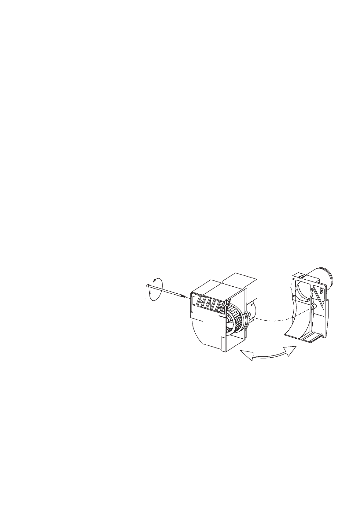
Combustion Air Fan
Access can be gained to the combustion
air fan by opening the fan case as shown
in the diagram.
Clean the blades regularly with a stiff
brush. Care should be taken to avoid damaging the fan blades. Check that the air
inlet into the fan is clean.
When re-assembling the fan casing ensure that the gasket is correctly located.
Inner Assembly
Open the hinged extension as follows:Remove the MultiBloc plug from its socket
on the control package.
Remove the safety bolts from the hinged extension. Remove the pin appropriate to the direction in which the head
is to be opened.
Open the hinged extension, disconnect the ignition electrode H.T . lead and if fitted the flame probe lead.
Remove the locking screw securing the inner assembly gas pipe to its manifold. Carefully withdraw the inner
assembly from the hinged extension.
Air Diffuser And Gas Nozzle
Clean using a stiff brush.
Ignition Electrode
Clean and check the electrode is not cracked or worn. Renew if necessary .
Check the settings of the ignition electrode and flame rectification probe, and reset if necessary. Replace all
components and covers, and secure all fittings. The burner is now ready for operation. Switch on the electricity
supply and gas supply to the burner.
SG10110501
Page 13

GAS COMMISSIONING SHEET
The details below are to be completed by the Commissioning Engineer
Installer’s Name : _________________________________________________________
Address :________________________________________________________________
_______________________________________________________________________
_______________________________________________________________________
Site Address : ____________________________________________________________
_______________________________________________________________________
_______________________________________________________________________
Appliance : Type :___________ Size : ___________ Serial No. : ___________
Burner : Type :___________ Size : ___________ Serial No. : ___________
Commissioning date : _________________________________
Guarantee Expiry date : _______________________________
Gas type : __________________________________________
Gas Pressure upstream of main gas governor :
a) Standing : __________________ mbar b) Running : ___________________mbar
Gas pressure at burner head ________________ mbar _____________ in.w.g.
Gas rate (High) ________________ m
Gas rate (Low) ________________ m
3
3
_____________ ft3/hr
_____________ ft3/hr
Heat input ________________ MJ/hr _____________ Btu/h
CO ________________ % _____________ %
CO
2
________________ % _____________ %
Gross flue gas temperature ________________ °C _____________ °F
Ambient temperature ________________ °C _____________ °F
Nett flue gas temperature ________________ °C _____________ °F
Efficiency ________________ % _____________ %
SG10120501
Page 14

BURNER SERVICE RECORD
The details below are to be completed by the Servicing Engineer
This sheet to be completed and signed following each service / adjustment
DATE DETAILS OF SERVICE SIGNATURE
SG10130501
Page 15

BURNER SERVICE RECORD
The details below are to be completed by the Servicing Engineer
This sheet to be completed and signed following each service / adjustment
DATE DETAILS OF SERVICE SIGNATURE
SG10130501
Page 16

FAULT FINDING
Any modifications to the installation or component settings resulting from actions suggested below may
require the re-establishment of the various settings as indicated earlier in this manual.
Burner Motor Fails T o S t art
Check:
• that the electrical supply is sufficient and the burner is correctly wired.
• all fuses for continuity and size.
• all control instruments are “calling for heat”.
• the gas train is electrically connected.
• the control box is not locked out (e.g. signal lamp faulty). (If the control box is locked out, press
the reset button).
• there is sufficient gas pressure.
• the burner probe is not earthed.
• the air pressure switch is in the “start” position, as follows: -
Switch off the electrical supply . Remove the plug-in assembly from the control box base. Check for an
open circuit between the air pressure switch terminals.
If there is continuity between terminals, turn the dial on the air pressure switch fully anticlockwise to the
minimum setting. If there is now an open circuit, the air pressure switch is in order, otherwise the air
pressure switch is faulty and must be renewed.
If the air pressure switch isn't in its made position the motor will start for approximately 2 to 3 seconds,
it then will lockout for 10 seconds before attempting a further start. If it is still in the made position a
lockout will occur.
Start Failure Without Ignition
Check:
• The air pressure switch is set correctly.
• The electrode is correctly set and the porcelain is not cracked.
• The ignition transformer is not faulty.
• The control box is not faulty.
Start Failure Without Flame
If the start flame is not properly established, the safety circuit of the sequence controller will cause
lockout in one second.
The cause may be insufficient signal to the flame detection device. Alternatively the flame signal circuit
may be incomplete, or there is insufficient gas to allow the flame monitoring device to take over and
signal the sequence controller to continue its cycle. This may be remedied by adjusting the fast initial lift
of the downstream safety valve.
Check:
• The probe is correctly positioned.
• For bad earth continuity/faulty wiring.
• The ignition tranformer for crossed polarity.
• The flame signal circuit is incomplete.
SG100 01 05
Page 17

FAULT FINDING Continued.....
Burner Fails T o Establish Main Flame.
Check:
• The gas valves are operating correctly.
• The combustion air is set correctly .
• There is sufficient gas.
• The control box is not faulty .
Incorrect Rotation Of Burner Motor
Motor rotates clockwise viewed from the shaft end. If the burner motor rotation is incorrect, the single
phase motor should be renewed. On three phase motors, interchange any two phases. In normal
circumstances, this will correct the rotation.
SG100 01 05
Page 18

Enertech Limited,
P O Box 1,
Vines Lane
Droitwich,
Worcestershire,
WR9 8NA
 Loading...