

Page 1

Installation & Maintenance Manual
PO Series Automatic Oil Burner
Fully Modulating
Oil Burner
Page 2

PO Series ContentsPage A.2
CC
CC
C
ONTENTSONTENTS
ONTENTSONTENTS
ONTENTS
IMPORTANT INFORMATION .............................................................................. A.4
SAFETY ................................................................................................................... A.4
EMERGENCY INSTRUCTIONS ........................................................................................ A.4
EUROPEAN BOILER EFFICIENCY DIRECTIVE (B.E.D.) ........................................................ A.4
GENERAL INFORMATION ................................................................................. B.1
INTRODUCTION ....................................................................................................... B.2
FEATURES ............................................................................................................... B.2
Burner Designation .............................................................................................................. B.2
Burner Capacity ...................................................................................................................B.2
Fuel .....................................................................................................................................B.2
Controls...............................................................................................................................B.2
Operating Mode ..................................................................................................................B.2
SITE CONDITIONS AND SERVICES ................................................................................ B.3
Flue and Chimney Requirements ......................................................................................... B.3
Plant Room Ventilation ........................................................................................................B.3
Existing Appliances ..............................................................................................................B.3
Oil Supply ...........................................................................................................................B.3
Electrical Power Supply ........................................................................................................B.4
BURNER PACKAGING, ASSEMBLY AND INSTALLATION ........................................................ B.4
Packaging For Transit ............................................................................................................B.4
Assembly And Installation ....................................................................................................B.4
Fitting To The Appliance.......................................................................................................B.4
Air Supply ............................................................................................................................B.5
Combustion Chamber Conditions ........................................................................................B.5
Electrical Power Supply ........................................................................................................B.5
TECHNICAL SPECIFICATION .............................................................................. C.1
BURNER SPECIFICATION SHEET .................................................................................... C.2
BURNER AND COMPONENT IDENTIFICATION .................................................................. C.3
BURNER OPERATION................................................................................................. C.3
BURNER CONTROLS ................................................................................................. C.3
Modulating Unit .................................................................................................................. C.3
Flame Monitor .....................................................................................................................C.5
BURNER OPERATING SEQUENCE .................................................................................. C.5
Burner Sequence Controller .................................................................................................C.5
RWF40 MODULATING CONTROL............................................................................... C.5
Operation ............................................................................................................................C.5
Basic display ........................................................................................................................ C.5
To change the working set point. ..........................................................................................C.5
To enter a new parameter ....................................................................................................C.6
COMBUSTION HEAD DETAILS ..................................................................................... C.6
COMMISSIONING ......................................................................................... D.1
INDIVIDUAL SETTING RECORD .................................................................................... D.2
Page 3

Page A.3
PO Series Contents
SAFETY ................................................................................................................... D.2
E
MERGENCY INSTRUCTIONS ........................................................................................ D.2
INSPECTION ............................................................................................................ D.2
INITIAL SETTINGS ..................................................................................................... D.3
DRY RUN .............................................................................................................. D.3
LIVE RUN ............................................................................................................... D.3
General .............................................................................................................................. D.3
Oil Supply Temperature And Pressure ................................................................................. D.4
Initial Checks ...................................................................................................................... D.4
MODULATING UNIT ................................................................................................. D.5
COMMISSIONING THE BURNER ................................................................................... D.6
Checking The Flame Signal ................................................................................................. D.6
Setting The Air Pressure Switch ........................................................................................... D.7
Final Checks........................................................................................................................ D.7
RWF40 MODULATION............................................................................................. D.7
On Completing Commissioning ........................................................................................... D.7
COMMISSIONING SHEET : OIL ................................................................................. D.11
E : OPERATION AND MAINTENANCE .................................................................. E.1
NORMAL OPERATION ................................................................................................. E.2
Automatic Modulation......................................................................................................... E.2
ROUTINE SAFETY CHECKS ...........................................................................................E.2
Combustion Air.................................................................................................................... E.2
Flame Detector .................................................................................................................... E.2
Combustion Air Pressure Switch ........................................................................................... E.2
ROUTINE MAINTENANCE ............................................................................................E.2
Combustion Air Fan ............................................................................................................. E.2
Burner Inner Assembly ......................................................................................................... E.3
Oil Filters ............................................................................................................................. E.3
Oil Preheater ....................................................................................................................... E.3
FAULT FINDING .........................................................................................................E.3
Modulating System .............................................................................................................. E.3
Incorrect Rotation of the Fan Motor ..................................................................................... E.3
Fan Motor Fails To Start ........................................................................................................ E.3
Fan Motor Starts And Burner Goes To Lockout ..................................................................... E.4
Start Flame Failure ............................................................................................................... E.4
Main Flame Is Not Established ............................................................................................. E.4
Fan Motor Only Runs Continuously ..................................................................................... E.4
SPARE PARTS ............................................................................................................E.4
BURNER SERVICE RECORD ..........................................................................................E.5
Page 4

PO Series ContentsPage A.4
IMPORTANT INFORMATION
SS
SS
S
AFETYAFETY
AFETYAFETY
AFETY
It is essential that the following instructions and adjustments are carried out by qualified engineers
that are experienced in forced draught pressure jet oil burner commissioning. Nu-way cannot be
held responsible for any consequential damage, loss or personal injury as a result of customers
failing to follow these instructions, or as a result of misuse.
EE
EE
E
MERGENCYMERGENCY
MERGENCYMERGENCY
MERGENCY
I I
I I
I
NSTRUCTIONSNSTRUCTIONS
NSTRUCTIONSNSTRUCTIONS
NSTRUCTIONS
P Series Burners are designed and constructed to meet all applicable European Directives.
When used in accordance with the instructions provided, P Series Burners are unlikely to produce
a hazardous condition. If, however, such a condition should arise in connection with the burner,
the appliance or any instrument, machine or service in the vicinity of the burner, the FUEL AND
ELECTRICITY SUPPLIES SHALL BE ISOLATED IMMEDIATELY and they shall remain isolated until
the fault has been identified and rectified.
EE
EE
E
UROPEANUROPEAN
UROPEANUROPEAN
UROPEAN
B B
B B
B
OILEROILER
OILEROILER
OILER
E E
E E
E
FFICIENCYFFICIENCY
FFICIENCYFFICIENCY
FFICIENCY
D D
D D
D
IRECTIVEIRECTIVE
IRECTIVEIRECTIVE
IRECTIVE
(B.E.D.) (B.E.D.)
(B.E.D.) (B.E.D.)
(B.E.D.)
All burners and boiler bodies marketed separately within the European Union must comply with
EN267 - Oil Burners, and EN303 - Heating Boilers. Burner adjustments must be made in accordance
with boiler manufacturers’ instructions, and these must include flue gas temperatures, average
water temperature and CO2 or O2 concentration.
Page 5

Page B.1
PO Series General Information
GENERAL INFORMATION
Page 6

PO Series General Information
Page B.2
II
II
I
NTRODUCTIONNTRODUCTION
NTRODUCTIONNTRODUCTION
NTRODUCTION
This handbook has been produced to enable users
to install, commission and use P Series burners
safely and efficiently. At each stage the conditions
that should be met and the adjustments and other
actions which should be carried out are detailed
and the locations of the various components and
adjustment mechanisms are identified. Where
appropriate, this information is supported by tables
and graphs.
Literature on the proprietary components used in
P Series burner systems is available on request.
FF
FF
F
EAEA
EAEA
EA
TURESTURES
TURESTURES
TURES
The P Series of fully automatic burner equipment
is offered for industrial and air heater applications.
This is a versatile range of fully modulating burners
with a turndown of 3:1.
P Series burners meet current test authority
requirements both in the UK and overseas.
P Series burners are designed for flange mounting
to the appliance. All components are pre-wired,
input and output circuits being grouped for ease
of connection to the power supply and to electrical
equipment on the burner head, air damper and
oil pumping and heating units.
Larger sizes of PO burners can be supplied with
air/steam oil atomisation in place of the usual
pressure jet.
This technique, for larger thermal ratings, reduces
emissions, increases turndown and prolongs oil
pump life because lower oil pressures can be used.
For more information contact Nu-Way.
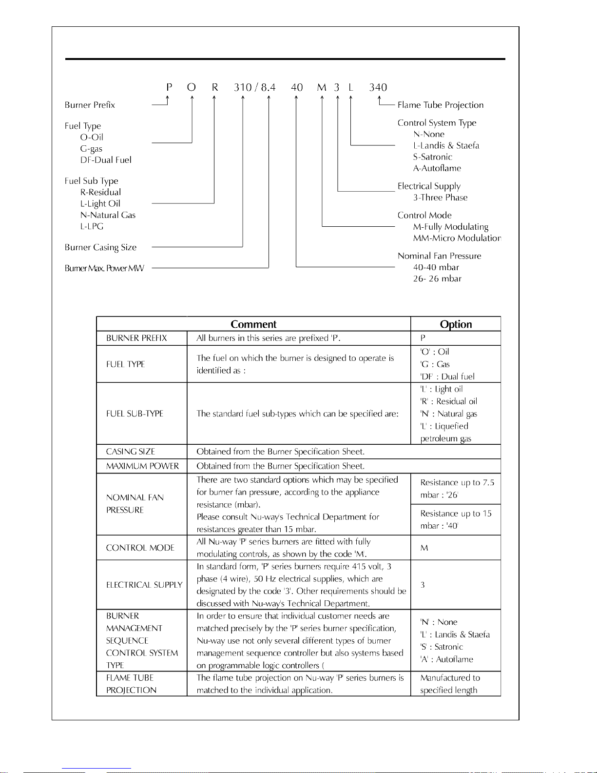
Burner Designation
Each burner is described by a comprehensive code
that defines all the important parameters of each
individual burner and is an important point of
reference for burners in service. In addition to the
burner casing size and maximum power output,
the code is composed as shown in the Table on
Page B.6.
Burner Capacity
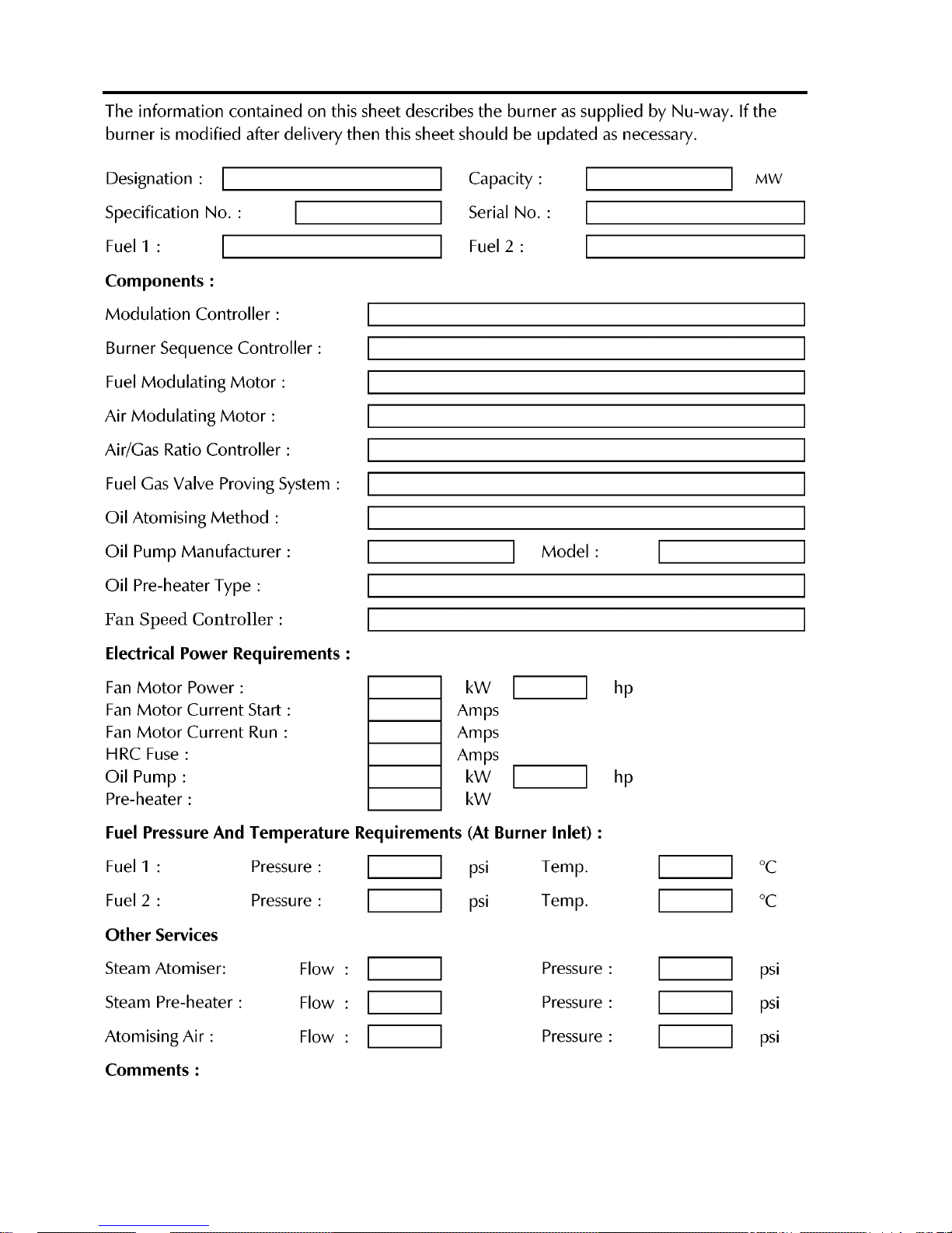
The burner output (based on the gross calorific
value) is shown on the Burner Specification Sheet
on Page C.2 Technical Details.
Fuel
The PO is available in two forms, to use distillate
or residual fuel oils.
Controls
The control panel, housed in a free-standing or
wall-mounted cabinet, is a purpose designed and
robustly constructed unit that complies with
relevant Standards and Codes of Practice and can
be tailored to individual customer requirements.
Depending on the burner specification, the control
panel incorporates such components as a burner
management sequence controller, a fuel selector
switch (for the dual fuel range), modulating control
gear, a starter for the combustion air fan, starters
for fuel pumps and boiler feed water pump, and
safety devices e.g. low and high water cut-out
relays.
Air for combustion can be adjusted to give
maximum efficiency. An air pressure switch
provides safe shutdown if the combustion air
supply becomes insufficient for complete
combustion.
A photo electric cell and automatic programming
control unit provide continuous flame supervision.
Operating Mode
P Series burners are all fully modulating offering a
standard turndown of 3 to 1.
To ensure efficient operation of any boiler, two
requirements are of paramount importance. The
air to fuel ratio must be kept to a minimum whilst
being sufficient for complete combustion and the
settings for this condition, once arrived at, are
accurately repeated. The temperature or pressure
of the boiler must be monitored by the control
system and the correct amounts of fuel and air fired
to achieve the set value, variations from this set
point must be minimised even when the load
changes.
Modulation By Electro-Mechanical Systems
P Series burners can be supplied with a Landis and
Staefa RWF40 modulating controller. This unit is
designed specifically for the control of boiler
temperature or steam pressure in oil- and gas-fired
heating plant.
The system comprises a reversible motor that is
coupled directly to the cam shaft of the modulating
unit. Two adjustable cams are mounted on this
shaft, one of which operates the air linkage and
the other, the modulating oil cam.
Page 7

Page B.3
PO Series General Information
SS
SS
S
ITEITE
ITEITE
ITE
C C
C C
C
ONDITIONSONDITIONS
ONDITIONSONDITIONS
ONDITIONS
A A
A A
A
NDND
NDND
ND
S S
S S
S
ERVICESERVICES
ERVICESERVICES
ERVICES
Flue and Chimney Requirements
It is important that:
- the flue pipe from the appliance and the joint
between this flue and the chimney are sealed
to prevent leakage of combustion products
- the flue pipe from the appliance does not
protrude into the chimney beyond the inside
wall
- the top of the flue or chimney shall be higher
than any roof within a radius of 10 metres
- checks are made to ensure that the chimney
is suitable for oil-fired appliances and that
the proposed installation complies with all
Local Authority and other regulations
covering such installations
- if more than one appliance is connected to a
common flue or chimney, the cross section
of this flue or chimney should be adequate
for the total volume of combustion products
from the appliances
- it is recommended that each appliance
should be exhausted into a separate flue.
Plant Room Ventilation
An adequate dust-free supply of fresh air is required
for the burner at both high and low levels in
accordance with the appropriate standards.
Existing Appliances
The appliance should be prepared for installation
of a P Series burner by thorough cleaning, including
the removal of all adhering tar, scale and dirt. An
inspection should also be carried out to ensure that
the appliance is in good condition. Any doubt
about the suitability of the appliance should be
referred to the manufacturer.
Oil Supply
In addition to the oil system supplied with the
burner, there are some requirements for the main
oil storage and supply system that supplies oil to
the burner system.
Main Oil Storage Tank
Residual fuel oils must be maintained at all times
at the temperature specified by the fuel supplier.
The Table on Page B.7 shows the temperatures and
pressures for Class D, E, F and G oils.
Oil Deliveries
It is good practice to shut down boilers whilst the
delivery of oil is made and allow 30 minutes for oil
sediment to settle out before re-starting the
burners.
Ring Main System
The oil from the tank must be supplied to the
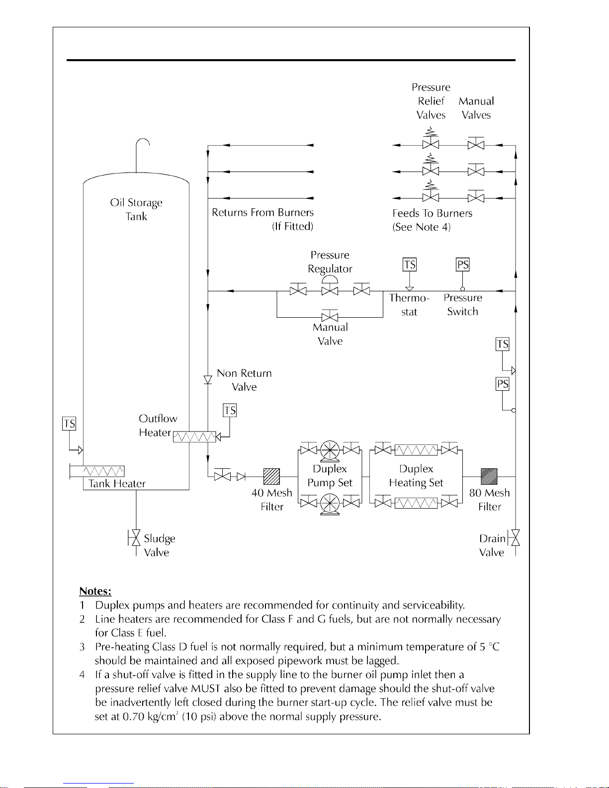
burner from a pumped ring main system. A typical
system is shown on Page B.8.
The inlet pressure of the oil will depend upon the
type of oil. Oil must be handled and delivered at
the temperatures and pressures shown in the Table
on the Burner Specification Sheet on Page C.2
Technical Specification.
The ring main pumps and pipe size must be
designed to at least 1.25 times the total swept
volume of the burner pump(s) it supplies. Oil supply
pipes must be constructed and installed to comply
with local conditions and appropriate Codes and
Standards. All pipework must be supported firmly,
and in the case of residual oils, lagged, traced and
thermostatically controlled. (The minimum pipe
size is 1.5 inch BSP).
Galvanised steel pipe should not be used.
It shall be of sufficient size to satisfy the pressure
and volume flow requirements of the burner under
all firing conditions.
Checks should be made to ensure that all meters
and other components are appropriately rated for
the maximum flow rate that is anticipated.
The final connection to the oil pump inlet port
should be made using the flexible pipe supplied
with the burner.
Precautions For Residual Oil
If heavy oils are heated to too high a temperature,
then lighter fractions will vaporise and this will
cause premature wear to the pump.
It is essential to filter heavy fuel oil before the
burner inlet. The filtration system should be
selected according to the individual features of the
installation but the diagram on Page B.8 gives some
basic guidelines. The ring main pressure should be
measured at the pump vacuum gauge port to allow
for any pressure drop caused by the filters.
For residual oil burners the pipework should be
insulated, trace heated and thermostatically
controlled.
Page 8

PO Series General Information
Page B.4
Electrical Power Supply
A three phase 50 Hz electrical supply is required.
Power requirements are listed on the Burner
Specification Sheet on Page C.2 Technical
Specification. The power supply provided must
comply with all relevant Codes and Standards.
BB
BB
B
URNERURNER
URNERURNER
URNER
P P
P P
P
ACKACK
ACKACK
ACK
AGINGAGING
AGINGAGING
AGING
, A, A
, A, A
, A
SSEMBLSSEMBL
SSEMBLSSEMBL
SSEMBL
YY
YY
Y
AA
AA
A
NDND
NDND
ND
I I
I I
I
NSTNST
NSTNST
NST
ALLALL
ALLALL
ALL
AA
AA
A
TIONTION
TIONTION
TION
Packaging For Transit
All PO Series modulating burners are supplied in
partly assembled form consisting of the following:
- burner head and air plenum chamber
- damper section with modulating air system
- modulating oil system as appropriate
- combustion air fan
- floor/wall mounted burner control panel
- a pumping and heating unit, or pumping unit
only for distillate oil burners, is supplied as a
separate component inclusive of flexible
pipes to make all necessary oil connections.
Assembly And Installation
P Series burners are supplied in partly assembled
form comprising some or all of the units indicated
above, depending upon the type(s) of fuel to be
fired.
Make sure that the appliance is suitable for the
heat input of the burner. If there is any doubt in
this area, reference should be made to the
appliance manufacturer.
Fitting To The Appliance
If the burner is to be fitted to a new appliance
refer to the manufacturer’s recommendations.
If the burner is to be fitted to an existing appliance,
the burner front plate and appliance must be
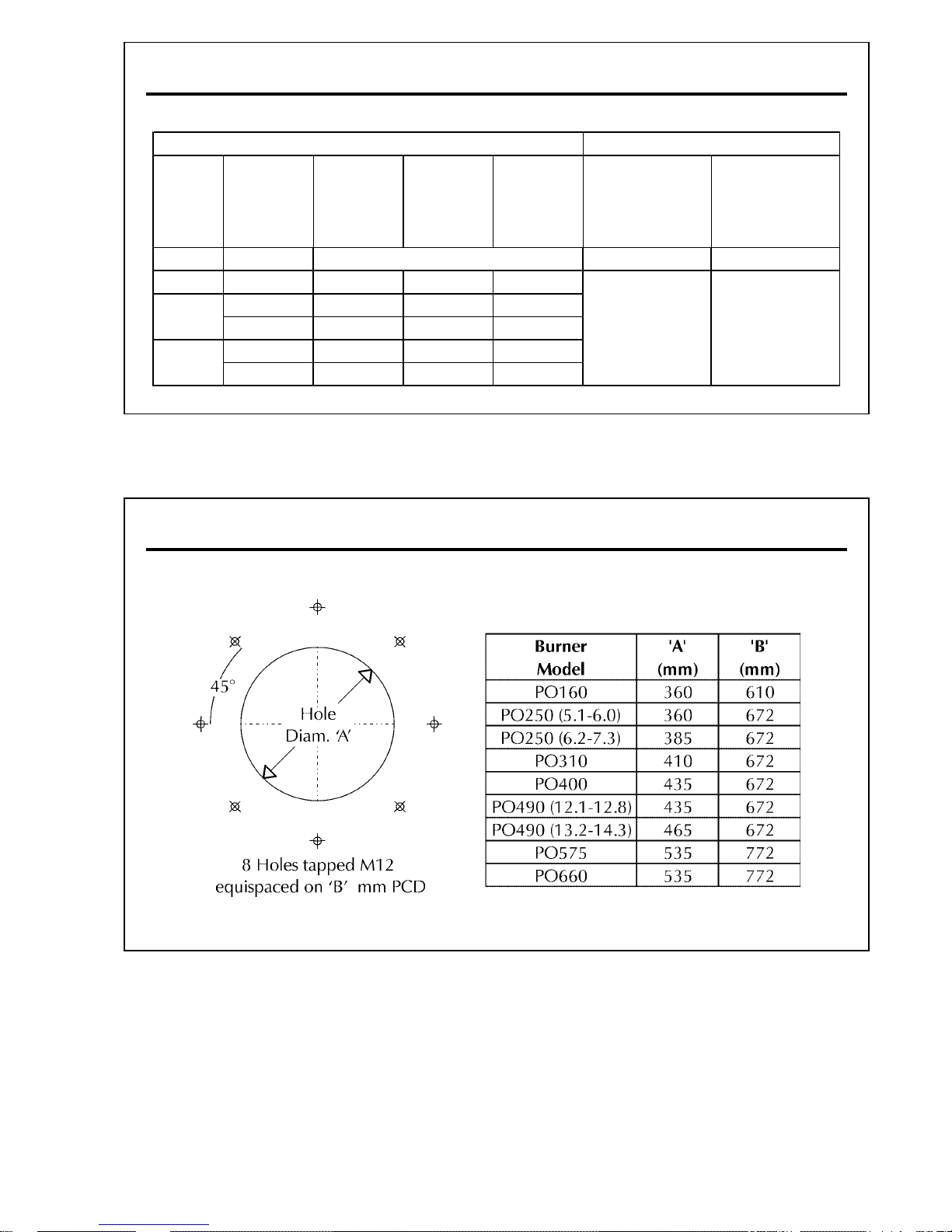
prepared; the details of the drilling arrangements
are shown on Page B.7.
The chimney, flues, passageways and heat transfer
surfaces on the existing appliances must be
cleaned. An inspection should be carried out to
ensure that the appliance is in good condition. Any
doubt about the suitability of the appliance should
be referred to the manufacturer.
To assemble the burner:
1 Fit the burner head to the prepared
appliance front plate.
2 Ensure that the joint between the burner and
the mounting flange is sealed effectively using
the gasket provided. The flame tube should
not generally extend beyond the inner face
of the furnace brickwork or the front plate
protection, except where extensions have
been expressly specified by the appliance
manufacturer.
3 Fit the damper section to the burner head
using the fasteners and gasket provided.
4 Position the combustion air fan and connect
the damper section using the fasteners and
gasket provided. Depending on the appliance
layout it may be necessary for the customer
to provide a connecting duct section between
the damper and the fan scroll (not supplied
by Nu-way).
5 For PO burners, place the pumping and
heating unit (or pumping unit) in the desired
position.
6 Connect the flexible oil pipes from the oil
inlet and return to the pumping (and heating)
unit, and the main oil supply pipework.
7 Locate the control panel in the desired
position and make the necessary connections
between the burner head, pumping (and
heating) unit and other auxiliary appliance
controls.
Reference must be made to the wiring diagrams
that are supplied with the burner (electrical
connection diagrams do not form part of this
handbook); all electrical wiring must comply with
all applicable Codes and Standards.
Air Supply
A floor-mounted fan provides the air supply for the
system, although the fan can be suspended for the
smaller sizes of burner. The flange on the
rectangular outlet is drilled for bolting onto the air
damper section of the burner unit. For safety, a
wire mesh guards the circular inlet of the fan. The
motor unit is enclosed, air-cooled and mounted
on a rigid base. The fan orientation/burner
mounting positions would have been specified by
the customer when the order was placed.
Page 9

SUPPLEMENT TO HANDBOOKS
SPECIFICATION CHANGES
In accordance with the Requirements for Electrical Installations BS
7671:2001 Amendment No 2 (the IEE wiring regulations), wiring colour
coding has been amended to Brown (L) and Blue (N) for single phase
power circuits and Brown (L1) Black (L2) and Grey (L3) and Blue (N) in
three phase power circuits from 1 June 2006.
Full details of the changes can be found in Amendment No 2 (AMD 14905)
to BS 7671:2001 - which is a free download from the IEE website
(www.iee.org/cablecolours). They are also within the new version of
BS7671:2001 (Incorporating Amds 1& 2) published on 31st March; this
new version of the Wiring Regulations can be identified by its brown cover.
Supplement Wiring.PMD
Revision 120606A
NEW WIRING COLOURS
Page 10

Page B.5
PO Series General Information
Electrical Power Supply
Connect the power supply to the burner observing
all applicable Codes and Standards. Reference
should be made to the wiring diagrams provided
in the instruction pack that is supplied with all P
Series burners and to those wiring diagrams in the
appliance manufacturer’s instructions.
All external auxiliary control circuits should be
connected with reference to the appropriate wiring
diagram. All systems and circuits should be checked
to ensure that correctly rated fuses are used.
Page 11
PO Series General Information
Page B.6
BB
BB
B
URNERURNER
URNERURNER
URNER
D D
D D
D
ESIGNAESIGNA
ESIGNAESIGNA
ESIGNA
TIONTION
TIONTION
TION
C C
C C
C
ODEODE
ODEODE
ODE
Page 12
Page B.7
PO Series General Information
BB
BB
B
URNERURNER
URNERURNER
URNER
M M
M M
M
OUNTINGOUNTING
OUNTINGOUNTING
OUNTING
D D
D D
D
ETET
ETET
ET
AILAIL
AILAIL
AIL
OO
OO
O
ILIL
ILIL
IL
H H
H H
H
ANDLINGANDLING
ANDLINGANDLING
ANDLING
T T
T T
T
EMPERAEMPERA
EMPERAEMPERA
EMPERA
TURESTURES
TURESTURES
TURES
A A
A A
A
NDND
NDND
ND
P P
P P
P
RESSURESRESSURES
RESSURESRESSURES
RESSURES
Fuel
Class
Viscosity
(Seconds)
Minimum
From Tank
Burner
Inlet
Atomising
kg/cm
2
psi
D 35 0.35 to 0.70 5 to 10
E 200 16 16 82
960 30 43 110
1500 36 65 118
3500 50 82 132
4200 55 86 140
Fuel Handling Temperatures (°C)
Fuel Delivery Pressures
Minimum 5 Recommended
4 to 5 57 to 71
F
G
Page 13
PO Series General Information
Page B.8
TT
TT
T
YPICYPIC
YPICYPIC
YPIC
ALAL
ALAL
AL
P P
P P
P
UMPEDUMPED
UMPEDUMPED
UMPED
O O
O O
O
ILIL
ILIL
IL
R R
R R
R
INGING
INGING
ING
M M
M M
M
AINAIN
AINAIN
AIN
Page 14

Page B.9
PO Series General Information
Page 15

PO Series General Information
Page B.10
AAD \PFinal\B_Gen\PO\B_Gen.pmd 250504A
Page 16

Page C.1
PO Series Technical Specification
TECHNICAL SPECIFICATION
Page 17
PO Series Technical SpecificationPage C.2
BB
BB
B
URNERURNER
URNERURNER
URNER
S S
S S
S
PECIFICPECIFIC
PECIFICPECIFIC
PECIFIC
AA
AA
A
TIONTION
TIONTION
TION
S S
S S
S
HEETHEET
HEETHEET
HEET
Page 18

Page C.3
PO Series Technical Specification
BB
BB
B
URNERURNER
URNERURNER
URNER
A A
A A
A
NDND
NDND
ND
C C
C C
C
OMPONENTOMPONENT
OMPONENTOMPONENT
OMPONENT
II
II
I
DENTIFICDENTIFIC
DENTIFICDENTIFIC
DENTIFIC
AA
AA
A
TIONTION
TIONTION
TION
The general arrangement of a PO burner employing
RWF40 Controller is shown in the diagram Burner
and Component Identification on Page C.7. An
enlarged view of the burner head casing is shown
in the diagram on Page C.8.
These diagrams are for illustrative purposes only
and actual components supplied may vary from
those shown.
All personnel concerned with commissioning and/
or operation of P Series burners should familiarise
themselves particularly with the information
presented in this section.
BB
BB
B
URNERURNER
URNERURNER
URNER
O O
O O
O
PERAPERA
PERAPERA
PERA
TIONTION
TIONTION
TION
When the boiler control calls for heat, the burner
modulating unit will travel to the ‘high flame’
position and interlock the control circuit. An air
pre-purge will take place at this position for a predetermined period, at the end of which the burner
sequence controller will stop until the modulating
unit has travelled to the ‘low flame’ position and
interlocked the control circuit again. The sequence
control will now recommence its operational cycle
and the burner will light and remain at low flame
until the high flame release signal is given by the
sequence control.
Under the instruction of the modulating controller,
the modulating unit will now move to high flame
and remain at this position until the desired boiler
temperature/pressure is attained. From this stage,
the modulating controller will drive the burner
towards the low flame position, but, depending
on the temperature/pressure, will stop in any
intermediate position between low and high
flame.
BB
BB
B
URNERURNER
URNERURNER
URNER
C C
C C
C
ONTROLSONTROLS
ONTROLSONTROLS
ONTROLS
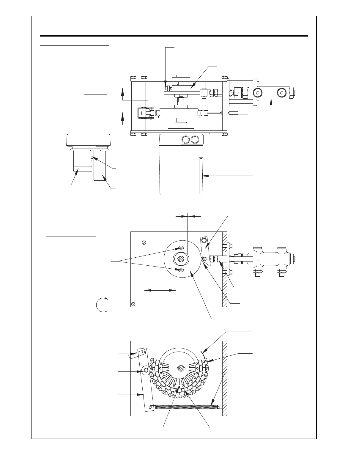
Modulating Unit
The Nu-way modulating unit consists of a reversible
servomotor, which is directly coupled to the
camshaft of the modulating unit. Two adjustable
cams are mounted on this shaft, one of which is
operating the burner air inlet control damper and
is of the variable contour type, the second cam is
the modulating oil cam (see illustrations on Page
C.18).
Oil System
The Burner Oil Control System Drawings on pages
C.10 & .11 show the burner hydraulic circuit. Oil
for combustion is drawn from the supply through
a fixed displacement pump and supplied direct to
the burner nozzle. A return line from the back of
the nozzle is connected to a ‘spill regulating valve’
which regulates the oil pressure at the nozzle
according to the position of an internal piston
which is actuated by the oil control cam in the
modulating unit.
Air Damper
To control the air for combustion, PO burners have
an adjustable multi-blade damper located in a
rectangular section attached directly to the burner
casing (diagrams on Pages C.7 and C.8). This
damper is driven directly by a servo-motor and
must be set during commissioning.
Air Diffuser
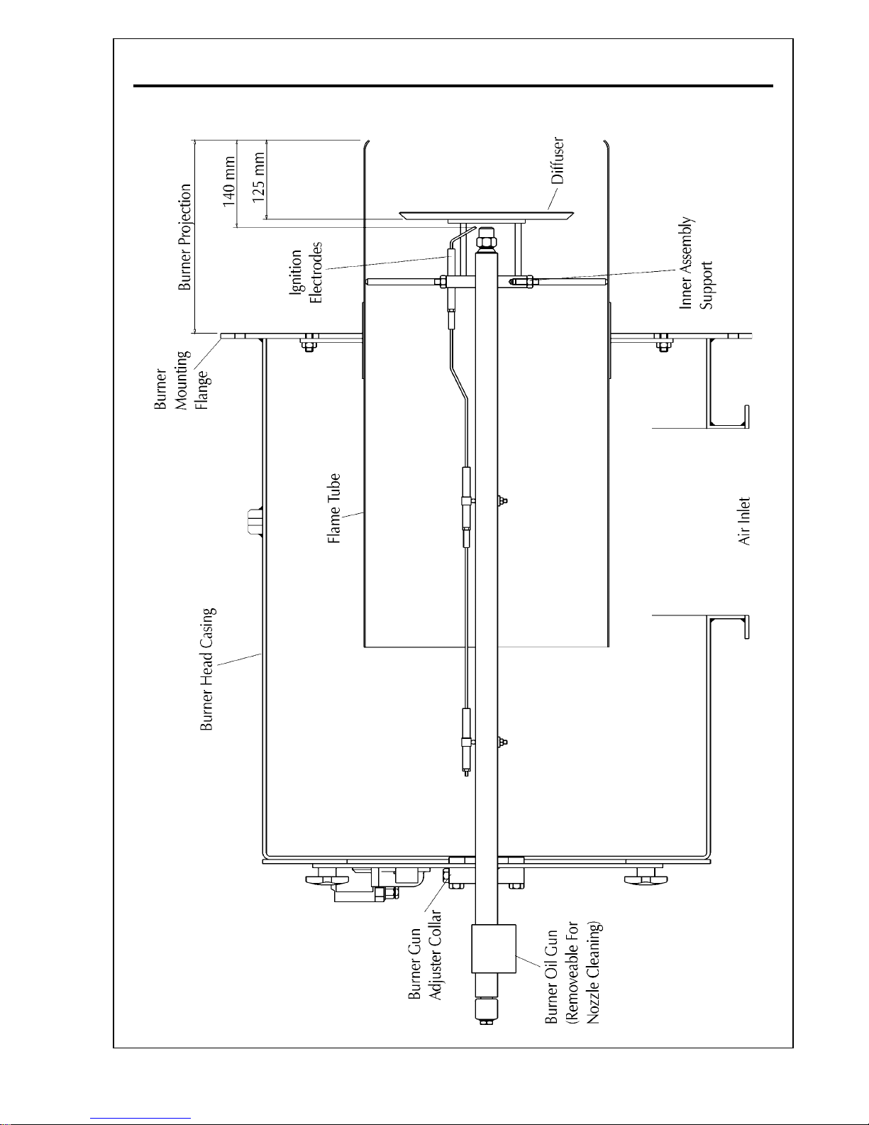
An air diffuser (shown in the diagram Burner Head
on Page C.15) is fitted to the front end of the inner
assembly and is located within the flame tube. It
directs the combustion air flow and creates a
pressure drop across the burner head, promoting
good air/fuel mixing and flame stability.
Air Pressure Switch
The air pressure switch is located on the rear of
the burner casing. Its function is to ensure that the
combustion air flow is adequate under all operating
conditions.
An air flow failure at any stage beyond the first few
seconds of the pre-purge period will result in a safe
burner shutdown.
Oil Controls
The components vary according to whether
distillate or residual oil is fired. In all cases a twopipe system is essential to ensure that the oil pump
remains primed. The oil must be supplied and
maintained at the temperature and pressure given
in the Table on Page B.8.
PO burners are supplied with an oil system where
specified, (see diagrams on Page C.10 Distillate Oil
Control Train Schematic and on Page C.11 Residual
Oil Control Train Schematic) consisting of :
- pumping/heating set
- oil manifold block
- oil valve (normally-closed; for distillate fuel
oil)
- inner gun assembly housing the oil nozzle
- oil solenoid valve (tip shut-off)
Page 19

PO Series Technical SpecificationPage C.4
- motorised spill control valve
- non-return valve
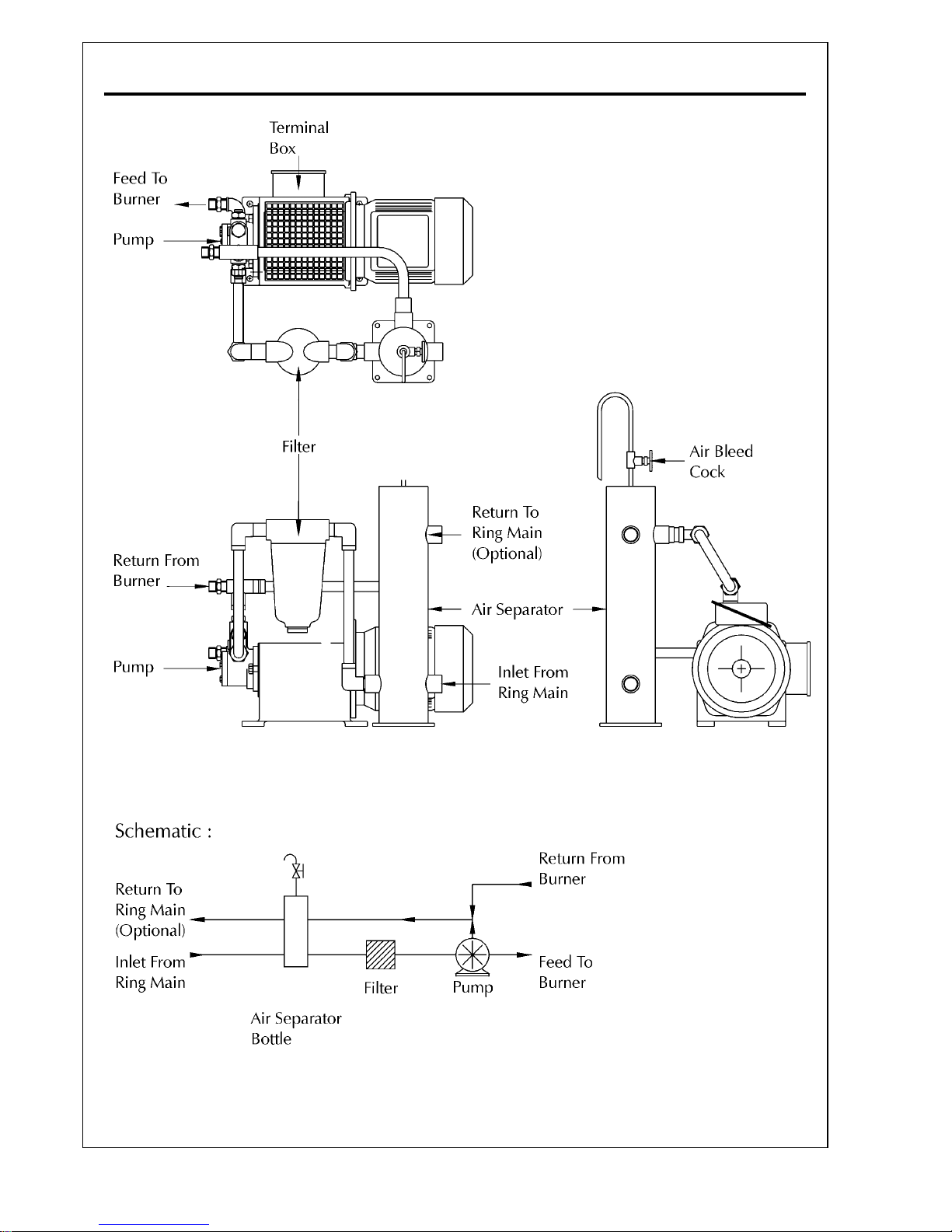
Pumping Set For Class D Fuel
The pump unit is free standing and comprises :
- oil pump
- motor
- oil filter(s)
- air bottle
The unit is assembled for floor mounting (see
diagrams Distillate Oil Pumping Set on Page C.12
and Oil Pumps on Page C.9). This unit is designed
to deliver the oil volume and pressure for the
required burner output.
Filter(s) are an integral part of the burner oil supply
system. The filter(s) should be checked regularly as
failure to do so may result in a drop in oil pressure
to the system.
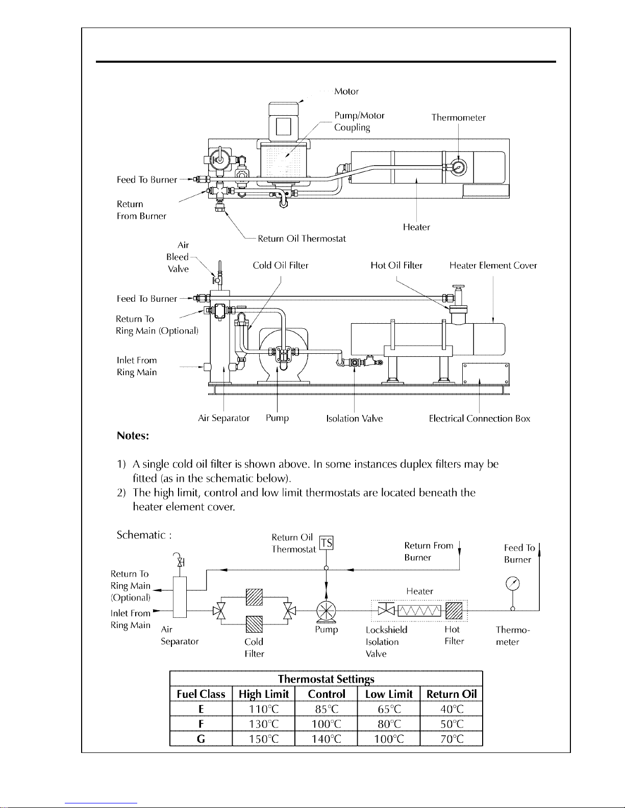
Pumping/Heating Set For Class E, F and G Fuels
The pump unit is free standing and comprises :
- oil pump
- motor
- hot oil filter
- cold oil filter(s)
- air bottle
- isolation valve (for residual fuel oil)
- return thermostat
- oil pre-heater tank with thermometer to
record the temperature of the oil at the outlet.
The pre-heater contains three thermostats:
- High limit thermostat
- Control thermostat
- Low limit thermostat (reverse acting)
The return thermostat is fitted in the return oil line
and will override the burner firing controls and start
the burner oil pump in order to maintain the
correct oil temperature in the nozzle and burner
pipework.
The thermostats should be set to the temperatures
specified in the Table forming part of diagram
Residual Oil Pumping Set on Page C.13.
The unit is pre-assembled on a base plate for floor
mounting (see diagrams Residual Oil Pumping Set
on Page C.13 and Oil Pumps on Page C.9). This
unit is designed to deliver the oil volume at
temperature and pressure for the required burner
output.
The pump should not be started when the oil is
cold as this can lead to damage to the pump and
couplings. The oil must be supplied and
maintained at the temperature and pressure given
in the Table on Page B.8.
Filter(s) are an integral part of the burner oil supply
system. The filter(s) should be checked regularly
as failure to do so may result in a drop in oil pressure
to the system.
Oil Control Train
The oil control train consists of a high pressure fuel
pump driven by the burner fan motor.
The oil nozzle throughput is controlled by a
variable orifice regulator situated in the return
supply oil line, and actuated by the Modulating
Unit described below. Solenoid operated normally
closed valves in the feed and return lines act as
the safety shut off for the nozzle.
Oil Manifold
The oil manifold block is located on the burner
casing and incorporates pressure gauges to measure
pump and spill pressures.
Solenoid Valve
For burners designed for distillate oil firing there is
a solenoid valve which is ‘normally-closed’ and is
located between the manifold block and the oil
lance (see diagram on Page C.10).
There is no solenoid valve fitted when the system
is designed to fire residual oil (see diagram on Page
C.11).
Inner Assembly Gun
The oil inner assembly gun is located in the middle
of the head casing assembly of the burner. Its
primary function is to carry oil from the oil pump
to the nozzle and to recirculate the oil back through
the spill regulating valve.
The spill-back atomiser utilises a spring loaded
orifice shut-off needle that is closed by the spring
of the actuating piston of the burner lance. This
guarantees a reliable shut-off under any condition.
This piston is driven by the supply pressure, via a
branch pipe, and controlled by a solenoid valve.
The needle opens by means of a spring and moves
to the correct position governed by a fixed stop on
the needle itself.
During the pre-purge period the needle holds the
orifice closed and the fuel oil circulates through
the lance and the atomiser under the set supply
and return pressure. When the solenoid is actuated,
immediate oil atomisation and ignition are
achieved.
Page 20

Page C.5
PO Series Technical Specification
Oil Nozzle
The oil nozzle is of the spill-back type and is fitted
to the front end of the inner assembly and located
in the flame tube. Page C.6.
The primary function of the nozzle is to spray oil
in a suitable pattern into the combustion air stream
at a rate appropriate to the appliance’s thermal
rating.
Oil Solenoid Valve (tip shut-off)
This valve operates the needle that releases oil to
the burner tip.
Non-return Valve
This valve allows flow in one direction only.
Control Panel
The control panel is a separate unit, free-standing
or wall-mounted, that is positioned adjacent to the
burner unit. The panel design depends upon
whether the boiler is for water heating or steam
raising. The sequence controller, relays, indicating
lamps, panel isolating switch etc. are contained
within this unit.
The burner is also fitted with an ignitor/terminal
box on the side of the burner casing. This is a
junction for all electrical components that are held
in the free standing control panel.
Connections must be made between the control
panel and the terminal box.
Flame Monitor
All P Series burners are fitted with continuous flame
supervision systems employing a photo electric cell
to detect the presence of a flame.
BB
BB
B
URNERURNER
URNERURNER
URNER
O O
O O
O
PERAPERA
PERAPERA
PERA
TINGTING
TINGTING
TING
S S
S S
S
EQUENCEEQUENCE
EQUENCEEQUENCE
EQUENCE
The operating sequence of P Series Burners begins
with checks on external interlocks and a check for
no flame, a pre-purge period on full air is then
initiated.
On completion of the pre-purge period the
appropriate oil valve or valves open, ignition is
initiated and low fire is established then the burner
modulates to high fire.
The burner sequence controller will then continue
to its normal operating position (i.e. it continues
to supervise the control functions and is therefore
able to shutdown the burner safely should this be
necessary), after driving to high fire, the modulating
controller will drive the burner towards the low
flame position, but, depending on the temperature/
pressure, will stop in any intermediate position
between low and high flame.the burner will be
controlled by the modulation controller.
Burner Sequence Controller
The burner sequence controller, together with the
flame monitoring system, provide a safe light-up
sequence for the burner.
A Landis & Staefa burner controller of the type
LAL2.25 (see the diagram Burner Sequence
Controller : Landis & Staefa LAL2.25 on Page C.14)
is fitted as standard.
RWF40 MRWF40 M
RWF40 MRWF40 M
RWF40 M
ODULODUL
ODULODUL
ODUL
AA
AA
A
TINGTING
TINGTING
TING
C C
C C
C
ONTROLONTROL
ONTROLONTROL
ONTROL
Operation
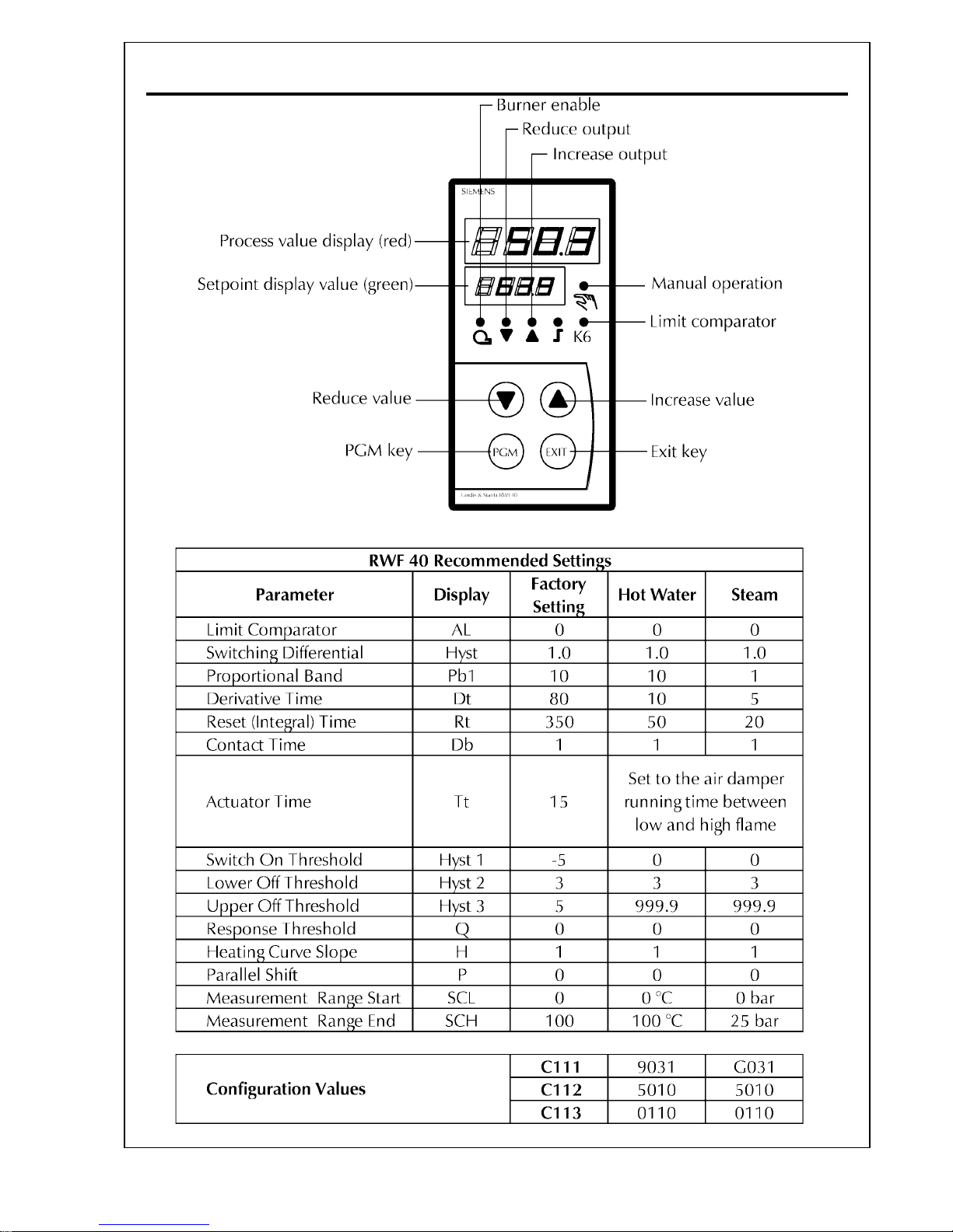
The burner employs a modulation system using a
Landis & Staefa RWF40 Universal Controller
(shown on Page C.17).
The modulating unit drives a reversible motor
that is coupled directly to the combustion air
damper linkage. When the RWF40 determines
that a change to the burner output is required,
the air damper and the oil spill back regulating
valve are adjusted accordinly.
Basic display
The diagram on Page C.17 shows the RWF40 after
switching on the supply voltage. This condition is
called the basic display. The actual operating value
and the currently active set-point will be shown.
Manual operation, self-optimization, the operating
parameter and the configuration levels can be
activated from this display.
To change the working set point.
The basic display shows the actual pressure/
temperature of the boiler in red and the required
set point pressure/temperature beneath in smaller
green digits.
One quick press of the PGM button, the display
changes to show the set point as the larger red
digits and the SPI in the lower small green digits.
Page 21
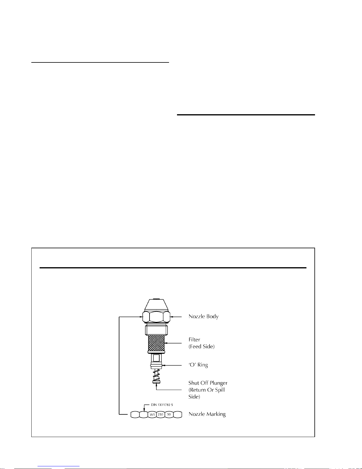
PO Series Technical SpecificationPage C.6
FF
FF
F
LUIDICSLUIDICS
LUIDICSLUIDICS
LUIDICS
O O
O O
O
ILIL
ILIL
IL
N N
N N
N
OZZLEOZZLE
OZZLEOZZLE
OZZLE
Alter the red display using the up/down buttons
to show the new required set point, press exit or
let the unit time out to return to the basic display
which should be the new set point figure.
To enter a new parameter
The parameters dictate the way in which the burner
firing rate alters in response to changes in the
pressure/temperature of the boiler.
A major factor that determines the need to change
the parameters is if the burner is fitted to a steam
or hot water boiler. The table on Page C.18
indicates the parameter and its setting for steam
and hot water boilers. It must be emphasised that
it is only an indication and any departure from
these settings should be made in small increments,
with time given to see how the burner is reacting
to the changed parameter.
Press and hold the PGM button down until the
green set point figure changes to an AL, the larger
upper figures show the value. Use the up/down
buttons to set the new value, press the PGM button
to enter the value and change to the next screen.
To cancel an entry press exit. Scroll through the
screens, (PGM button) modifying any value found
to be in error (up/down buttons). At the last screen
the PGM button will return the controller to the
original operating display.
At any point in the procedure the original
operating display can be obtained by letting the
unit time out, the value in the display at the time
out will be accepted.
A value can only be altered within the permitted
range of that parameter. All other parametrs must
remain as supplied.
Note: The detector range parameters SCL & SCH
are given as °C for Hot Water (temperature) and
bar for Steam (pressure).
CC
CC
C
OMBUSTIONOMBUSTION
OMBUSTIONOMBUSTION
OMBUSTION
H H
H H
H
EADEAD
EADEAD
EAD
D D
D D
D
ETET
ETET
ET
AILSAILS
AILSAILS
AILS
The combustion Head and Inner assembly are
shown in the diagram Burner Head on Page C.15.
Page 22
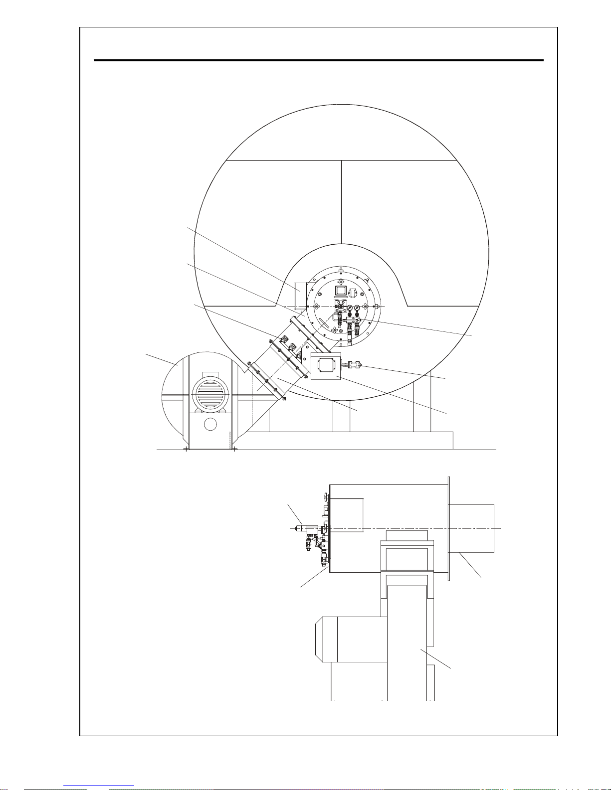
Page C.7
PO Series Technical Specification
BB
BB
B
URNERURNER
URNERURNER
URNER
A A
A A
A
NDND
NDND
ND
C C
C C
C
OMPONENTOMPONENT
OMPONENTOMPONENT
OMPONENT
I I
I I
I
DENTIFICDENTIFIC
DENTIFICDENTIFIC
DENTIFIC
AA
AA
A
TIONTION
TIONTION
TION
Combustion Air
Control Damper
Ignitor/Terminal
Box Assembly
Oil Valve
Assembly
Burner
Head Casing
Transition
Ductwork
Combustion
Air Fan
Modulating Cam Uni
t
Oil Lance
Flame Tube
Inner Assembly
Access Plate
Combustion Air Fan
This diagram is for
illustrative purposes
only.
Actual components
supplied may vary from
those shown.
Please refer to the
Burner Specification
Sheet and the
drawings elsewhere in
this manual for details
of the components
supplied.
Oil spill control valve
Page 23
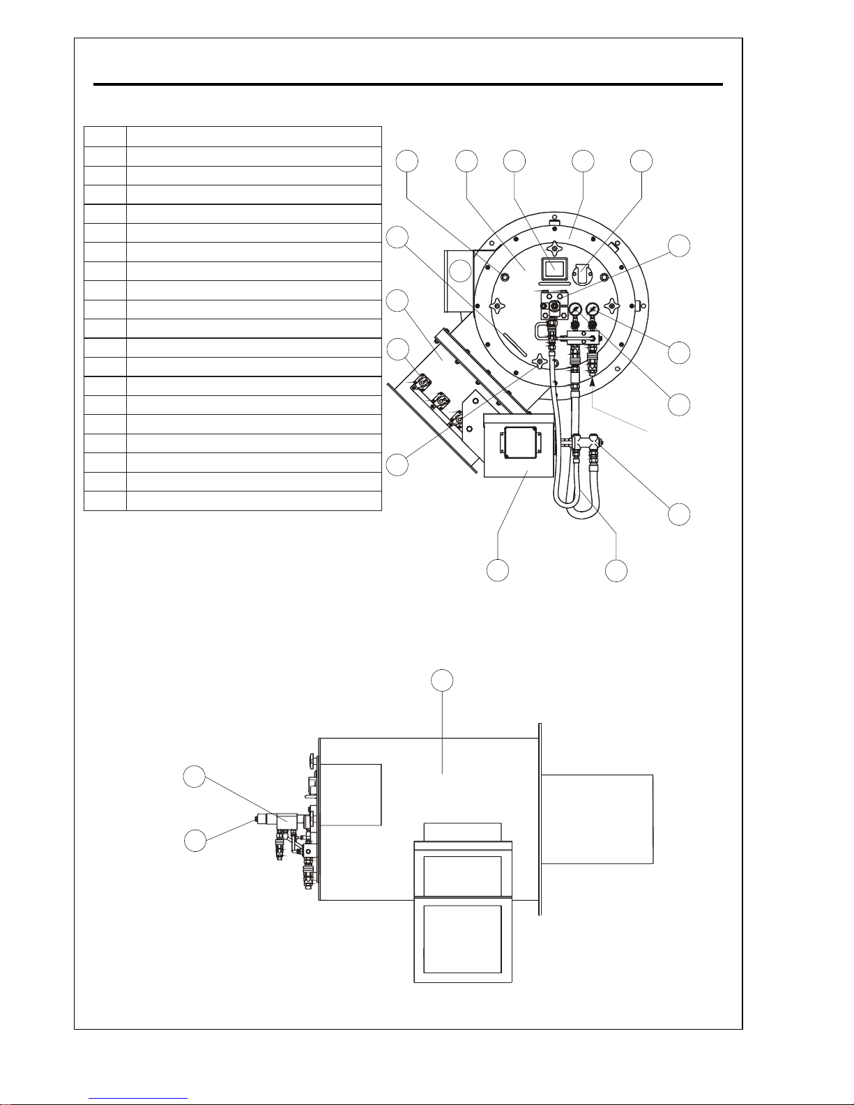
PO Series Technical SpecificationPage C.8
metItnenopmoC
1)'a'x3(tekcoSdoRediuG
2etalpkcaBylbmessArennI
3ssalGthgiS
4gniRrotpadAetalpkcaB
5redloHlleC.V.U
6kcolBpmalCecnaLrenruB
7egauGerusserPliOtelnI
8egauGerusserPliOkcaBllipS
9evlaVlipS
01eniLdeelBffo-tuhSpiTelzzoN
11tinUmaCdnarotoMgnitaludoM
21)'b'x4(stuNgniniateRetalpkcaB
31enaVlortnocriA
41tinUrepmadriA
51ylbmessAkcolBlanimreTdnarotingI
61seldnaHlawardhtiWetalpkcaB
71gnisaCdaeHrenruB
81dioneloSffo-tuhSpiTelzzoN
91ecnaLliOkcaBllipS
18
20
19
BB
BB
B
URNERURNER
URNERURNER
URNER
ANDAND
ANDAND
AND
C C
C C
C
OMPONENTOMPONENT
OMPONENTOMPONENT
OMPONENT
I I
I I
I
DENTIFICDENTIFIC
DENTIFICDENTIFIC
DENTIFIC
AA
AA
A
TIONTION
TIONTION
TION
D D
D D
D
ETET
ETET
ET
AILAIL
AILAIL
AIL
6
7
8
1 23 4 5
16
13
14
12
11
9
10
15
a
a
b
b
b
b
a
Oil Inlet from
Pump Unit
Page 24
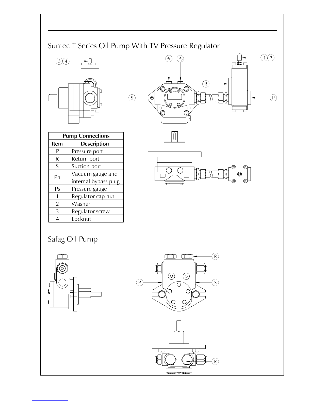
Page C.9
PO Series Technical Specification
OO
OO
O
ILIL
ILIL
IL
P P
P P
P
UMPSUMPS
UMPSUMPS
UMPS
Page 25
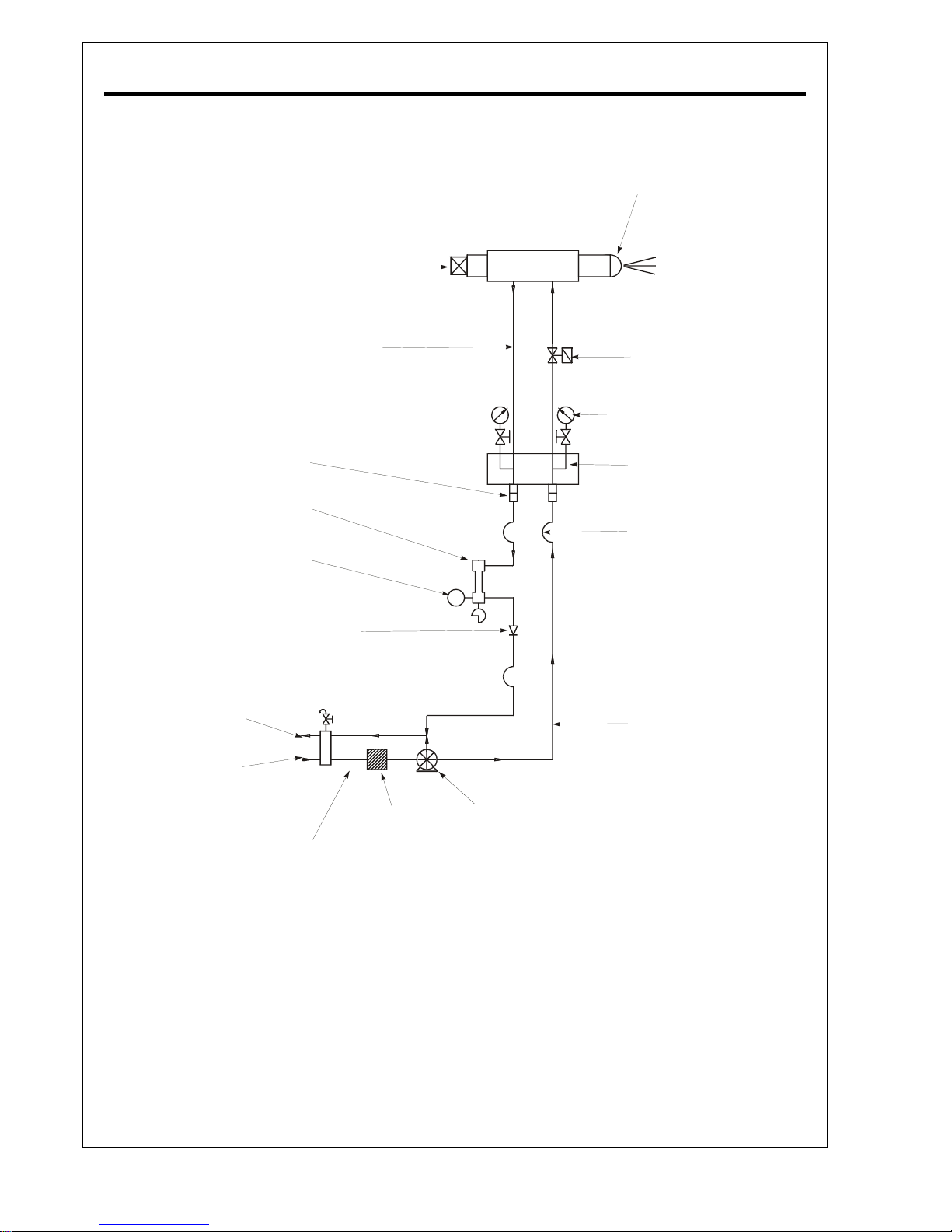
PO Series Technical SpecificationPage C.10
DD
DD
D
ISTILLISTILL
ISTILLISTILL
ISTILL
AA
AA
A
TETE
TETE
TE
O O
O O
O
ILIL
ILIL
IL
C C
C C
C
ONTROLONTROL
ONTROLONTROL
ONTROL
T T
T T
T
RAINRAIN
RAINRAIN
RAIN
S S
S S
S
CHEMACHEMA
CHEMACHEMA
CHEMA
TICTIC
TICTIC
TIC
Notes:
1 All interconnecting pipework must have a minimum bore of 19mm (3/4") and must be pressure
rated for 42kg/cm².
2 Pipework connections between the burner oil system and the separate pumping set are not
supplied by Nu-Way.
3 Connections to the ring main on the air separator bottle air 1" BSP.
.
Spill Back Nozzle
Tip Shut Off
Solenoid Valve
Solenoid Valve
Pressure Guages
Manifold Block
Quick Release
Couplings
Flexible Connections
Spill Control Valve
Non Return
Valve
Feed To Burner
Return from Burner
Feed
Return
Pump
Cold Filter
Air Separator
Return to
Ring Main
(Optional)
Inlet from
Ring Main
Pressure Switch
Burner Mounted
Components
Pumping Set
Components
Page 26
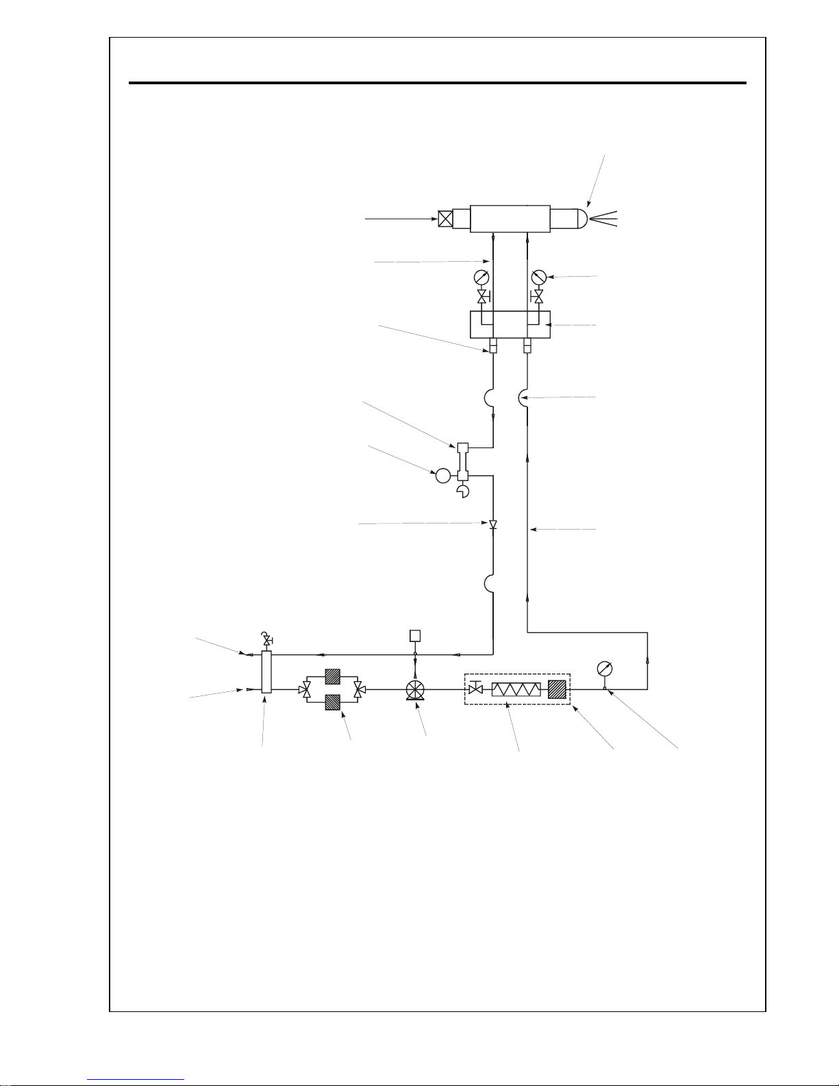
Page C.11
PO Series Technical Specification
RR
RR
R
ESIDUESIDU
ESIDUESIDU
ESIDU
ALAL
ALAL
AL
O O
O O
O
ILIL
ILIL
IL
C C
C C
C
ONTROLONTROL
ONTROLONTROL
ONTROL
T T
T T
T
RAINRAIN
RAINRAIN
RAIN
S S
S S
S
CHEMACHEMA
CHEMACHEMA
CHEMA
TICTIC
TICTIC
TIC
Spill Back Nozzle
Tip Shut Off
Solenoid Valve
Pressure Guages
Manifold Block
Quick Release
Couplings
Flexible Connection
s
Spill Control Valve
Non Return
Valve
Feed To Burner
Return from Burner
Feed
Return
Pump
Cold Filter
Air Separator
Return to
Ring Main
(Optional)
Inlet from
Ring Main
Pressure Switch
Lockshield
Isolation Valve
Hot
Filter
Thermometer
Burner Mounted
Components
Pumping/Heating Set
Components
Notes:
1 All interconnecting pipework must have a minimum bore of 19mm (3/4") and must be
pressure rated for 42kg/cm².
2 Pipework connections between the burner oil system and the separate pumping set are
not supplied by Nu-Way.
3 Connections to the ring main on the air separator bottle air 1" BSP.
4 On residual fuel oil burners this pipework must be maintained at the burner atomising
temperature and in the case of class F and class G fuels must also be trace heated.
Page 27
PO Series Technical SpecificationPage C.12
DD
DD
D
ISTILLISTILL
ISTILLISTILL
ISTILL
AA
AA
A
TETE
TETE
TE
O O
O O
O
ILIL
ILIL
IL
P P
P P
P
UMPINGUMPING
UMPINGUMPING
UMPING
S S
S S
S
ETET
ETET
ET
Page 28
Page C.13
PO Series Technical Specification
RR
RR
R
ESIDUESIDU
ESIDUESIDU
ESIDU
ALAL
ALAL
AL
O O
O O
O
ILIL
ILIL
IL
P P
P P
P
UMPINGUMPING
UMPINGUMPING
UMPING
/H/H
/H/H
/H
EAEA
EAEA
EA
TINGTING
TINGTING
TING
S S
S S
S
ETET
ETET
ET
Page 29
PO Series Technical SpecificationPage C.14
BB
BB
B
URNERURNER
URNERURNER
URNER
S S
S S
S
EQUENCEEQUENCE
EQUENCEEQUENCE
EQUENCE
C C
C C
C
ONTROLLERONTROLLER
ONTROLLERONTROLLER
ONTROLLER
: L : L
: L : L
: L
ANDISANDIS
ANDISANDIS
ANDIS
& S & S
& S & S
& S
TT
TT
T
AEFAEF
AEFAEF
AEF
AA
AA
A
L L
L L
L
AL2.25AL2.25
AL2.25AL2.25
AL2.25
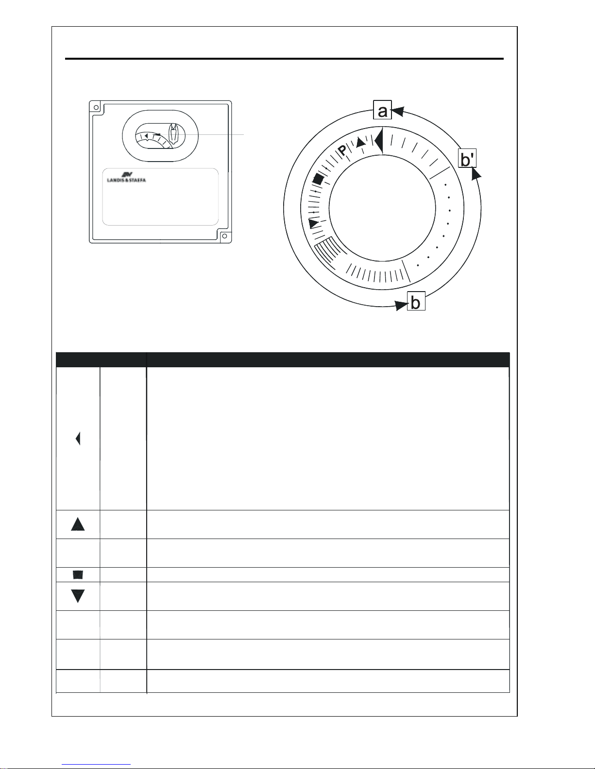
Enlarged Detail Of Sequence Indicator
Sequence
Indicator
P
1
I
In the event of a fault condition the sequence
disc stops rotating, with the symbol appearing
above the indicator mark indicating the nature
of the fault.
If the fault leads to a lockout condition the
orange lockout indicator will be illuminated.
Symbol Lockout Fault
No
No
Yes
Yes
No
None Yes
Yes
Yes
1
Failure of one or more of the pre-start checks. Before allowing the
sequence to begin the unit carries out the following checks:
Burner Controller not in lockout position.
A
ir Damper Closed (proved by limit switch supplying voltage from terminal
11 to terminal 8).
Fuel Valves closed (
p
roved by limit switch supplying voltage to terminal 12)
Fuel pressure switch, Limit Thermostat or Limit Pressure Switch all closed
(proved by continuity between terminals 4 and 5)
Interru
p
tion to sequence whilst controller waits for the air damper to drive to
open position (proved by servo motor limit switch).
Lockout caused by the failure of the air pressure switch to changeover from
the 'no air' position shortly after the pre-purge.
Lockout caused by a fault in the flame supervision circuit.
Interruption to sequence whilst controller waits for the air damper to
drive to start position (proved by servo motor limit switch).
Lockout during the pre-ignition period not marked by a symbol is
usually caused by premature flame signal.
Lockout caused by the absence of a flame signal at the end of the first safety
period (time for start flame establishment).
Lockout caused by the loss of the flame signal during normal operation.
Page 30
Page C.15
PO Series Technical Specification
BB
BB
B
URNERURNER
URNERURNER
URNER
H H
H H
H
EADEAD
EADEAD
EAD
Page 31
PO Series Technical SpecificationPage C.16
EE
EE
E
LECTRODELECTRODE
LECTRODELECTRODE
LECTRODE
S S
S S
S
ETTINGETTING
ETTINGETTING
ETTING
D D
D D
D
ETET
ETET
ET
AILAIL
AILAIL
AIL
Page 32
Page C.17
PO Series Technical Specification
MM
MM
M
ODULODUL
ODULODUL
ODUL
AA
AA
A
TIONTION
TIONTION
TION
C C
C C
C
ONTROLLERONTROLLER
ONTROLLERONTROLLER
ONTROLLER
: L : L
: L : L
: L
ANDISANDIS
ANDISANDIS
ANDIS
ANDAND
ANDAND
AND
S S
S S
S
TT
TT
T
AEFAEF
AEFAEF
AEF
AA
AA
A
RWF40 RWF40
RWF40 RWF40
RWF40
Page 33
PO Series Technical SpecificationPage C.18
MM
MM
M
ODULODUL
ODULODUL
ODUL
AA
AA
A
TINGTING
TINGTING
TING
U U
U U
U
NITNIT
NITNIT
NIT
(Cams shown in the Low
Flame Position)
Motor Unit
Camstack
Lever
Servomotor
Oil Spill Back
Regulating Valve
Oil Cam -
A
Air Cam -
B
Oil Cam Adjusting Screw
Oil Cam Hub
Rotation for High
Flame Position
Locking
Screws
Spill Pressure
Reduce Increase
Cam Disk
Roller
Adjustable Plunger
Cam Follower
Throw
Oil Cam View On -
A
Adjuster Locking Screws
Profile Adjuster
Profile Band
Damper Drive Arm
Cam Lever
Roller
Retaining Saddl
e
Return Spring
A
ir Cam View On -
B
Page 34

Page C.19
PO Series Technical Specification
Page 35

PO Series Technical SpecificationPage C.20
AAD PFinal\C_Tech\Po\RWF40\C_Tech.pmd 250504A
Page 36

Page D.1P Series Commissioning
COMMISSIONING
Page 37

P Series CommissioningPage D.2
II
II
I
NDIVIDUALNDIVIDUAL
NDIVIDUALNDIVIDUAL
NDIVIDUAL
S S
S S
S
ETTINGETTING
ETTINGETTING
ETTING
R R
R R
R
ECORDECORD
ECORDECORD
ECORD
This manual contains commissioning sheets (Page
D.11) of essential information that should be
completed by the commissioning engineer with
individual details of the burner. These details
should be verified periodically and changed as
adjustments occur.
SS
SS
S
AFETYAFETY
AFETYAFETY
AFETY
IIt is essential that commissioning be undertaken
only by suitably qualified and experienced
personnel. In the case of P Series Burners,
commissioning engineers should be experienced
in commissioning forced draught, fully modulating
oil burners.
Nu-way can accept no responsibility for
consequential loss, damage or injury, which results
from a failure to follow the commissioning
instructions provided or from commissioning
procedures being undertaken by unqualified
personnel.
It is the commissioning engineer’s responsibility
to ensure that all settings are in accordance with
the appropriate local standards and applicable
codes of practice.
EE
EE
E
MERGENCYMERGENCY
MERGENCYMERGENCY
MERGENCY
I I
I I
I
NSTRUCTIONSNSTRUCTIONS
NSTRUCTIONSNSTRUCTIONS
NSTRUCTIONS
P Series Burners are designed and constructed to
meet all applicable European Directives.
When used in accordance with the instructions
provided, P Series Burners are unlikely to produce
a hazardous condition. If, however, such a
condition should arise in connection with the
burner, the appliance or any instrument, machine
or service in the vicinity of the burner, the FUEL
AND ELECTRICITY SUPPLIES SHALL BE
ISOLATED IMMEDIATELY and they shall remain
isolated until the fault has been identified and
rectified.
II
II
I
NSPECTIONNSPECTION
NSPECTIONNSPECTION
NSPECTION
Before commissioning is started it is important to:
- Check that the electrical wiring is complete
and complies with all applicable Codes and
Standards.
- Ensure that the fuses are fitted and are of the
correct ratings.
- Check electrical earthing.
- Verify that the oil pipework is correctly sized
and that it has been checked for leakage.
- Check that the appropriate modulating
detector which is supplied loose with each
burner, is fitted correctly to the appliance.
(Technical Specification Pages C.2).
- Make all personnel involved in the
commissioning aware of the location of the
emergency oil and electricity isolation points.
- Check that the appliance's ventilation and
flueing arrangements are adequate.
- Ensure that any warning notices appropriate
to the commissioning procedure are in
position.
- Ensure that all necessary tools and test
equipment are available and ready for use.
Essential items include temperature
measuring instruments for measuring flue gas
and appliance water temperatures, and a
means of analysing the flue products for
carbon dioxide (CO2), oxygen (O2), carbon
monoxide (CO) and smoke.
- Check that all relevant documentation is
available, including, where appropriate:
- The agreed plant performance
specification.
- Plant drawings and pipework layouts.
- Electrical logic and wiring diagrams.
- Certificates confirming satisfactory
completion of procedures such as
soundness testing, purging and
electrical safety tests.
- Commissioning, operating, emergency
shutdown and maintenance
instructions for the plant.
- Establish that the operation of plant other
than that being commissioned will not have
an adverse effect on the operation of the
plant to be commissioned, and similarly, that
the operation of the plant to be
commissioned will not have an adverse effect
on other plant.
- Confirm that the operation of adjacent plant
and machinery will not constitute a hazard
to the personnel involved in commissioning.
- Establish that the appliance is in an
appropriate and safe condition to be fired;
for example, that there is water in the boiler.
- Set the appliance controls to call for heat.
Page 38

Page D.3P Series Commissioning
II
II
I
NITIALNITIAL
NITIALNITIAL
NITIAL
S S
S S
S
ETTINGSETTINGS
ETTINGSETTINGS
ETTINGS
To prepare the burner for commissioning:
1. Check that the electrical power to the control
panel and to the burner is off.
2. Remove the cover from the Landis & Staefa
SQM10 air damper servo-motor and check
the cam positions. Adjust if necessary.
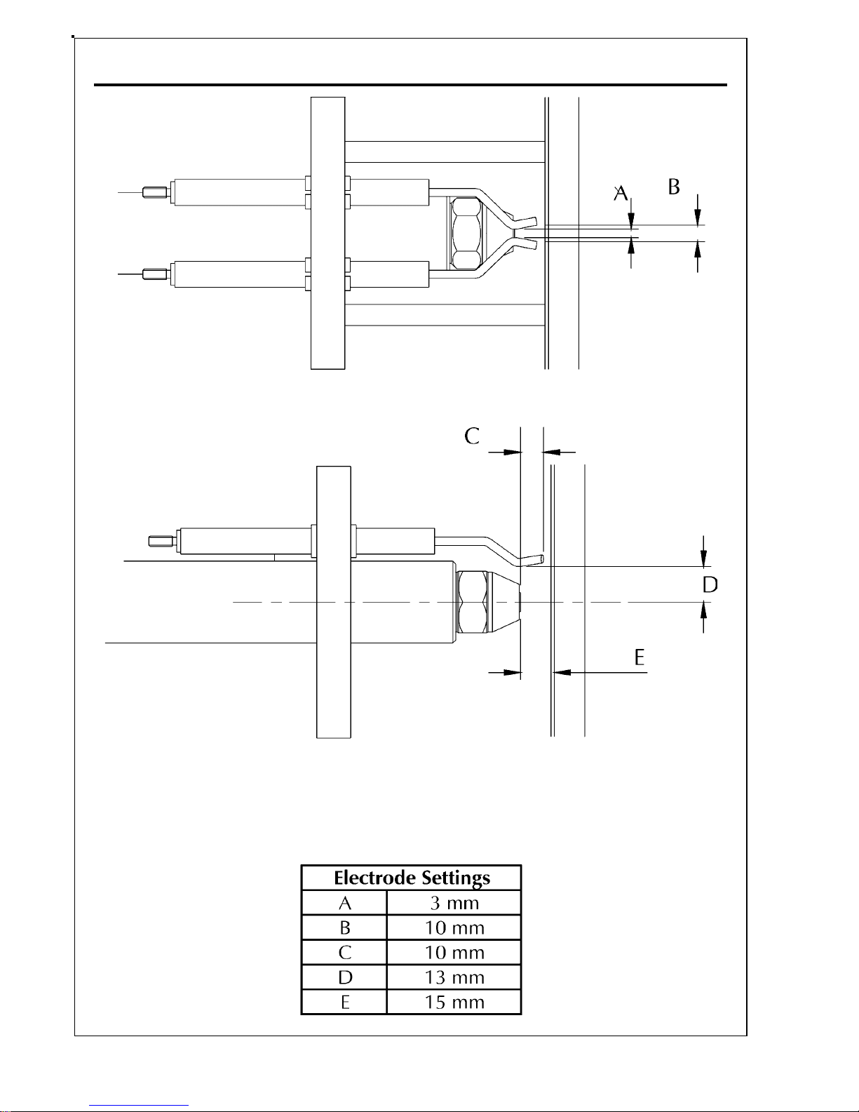
3. Check and if necessary re-set the ignition
electrode gaps. The burner head
arrangement is shown on Page C.16 and
access instructions are provided in Operation
and Maintenance on Page E.3.
4. When the inner assembly is out and whilst
the back cover is off, check that the air
damper is in the closed position. If not in the
closed position put power on to the control
panel. DO NOT SWITCH ON THE BURNER.
The damper servomotor should run to the
closed position and stop. After the motor has
stopped the damper blades should be fully
closed, if not adjust the blades on their
spindles.
Warning - In some applications the fan may be
running so care must be exercised.
5. Set the air pressure switch to minimum. (This
must be re-set to the desired level during
commissioning).
DD
DD
D
RYRY
RYRY
RY
R R
R R
R
UNUN
UNUN
UN
The following procedure should be followed. It is
important that a complete and flawless dry run be
completed before fuel is supplied to the system.
1. Check that the electrical supply to the control
panel and burner are turned off.
2. Switch the burner On/Off switch to ‘OFF’
position.
3. Check that the oil pipework and ringmain
are ready for operation.
4. Set the Hand/Auto switch on the control
panel to the ‘Hand’ position.
5. Establish the electrical supply to the control
panel. Press the sequence controller re-set
button if necessary. If the sequence controller
is not at its start position it will motor round
to its start position and wait.
6. Ensure that the flame detection system
detects the presence of a simulated flame or,
where permissible an independent flame
source.
Remove the flame detector from the burner,
expose the detector to a flame or simulated
flame. This should cause a lockout indicated
by illumination of the corresponding
indicator light on the control panel.
7. Replace the flame detector in its housing in
the burner. Reset the sequence controller
using the ‘Reset’ button on the control panel.
8. Switch off the electrical power supply to the
control panel and to the burner.
LL
LL
L
IVEIVE
IVEIVE
IVE
R R
R R
R
UNUN
UNUN
UN
General
The instructions in this section are presented as a
sequence. No separate set of actions (for example,
checking the flame signal) should be followed in
isolation without paying particular attention to any
safety precautions such as isolating the electrical
supply to the burner which must precede such
actions. At all stages, the operation of the burner
should be checked against the programming
sequence controller diagram (Technical
Specification Page C.14).
Before proceeding check again that :
· The electrical wiring is complete and
complies with all relevant Codes and
Standards.
· All fuses are fitted, and are of the correct
ratings.
· The oil supply pipework is correctly installed
and has been leak tested. If, at any time
during commissioning, there is a fuel leak,
FUEL AND ELECTRICITY SUPPLIES SHALL
BE ISOLATED IMMEDIATELY and the leak
sealed before proceeding.
· The appliance is in an appropriate and safe
condition to be fired.
· The appliance controls are set to call for heat.
Oil Supply Temperature And Pressure
Check that the temperature and pressure of the
oil delivered to the burner are as stated in General
Information Page B.8. If residual fuel is used check
that the oil supply is at the correct temperature.
For residual oil ensure that pressure inlet to the
pump is correct, for distillate oil pressure set to
1bar.
Page 39

P Series CommissioningPage D.4
Initial Checks
1. Remove the access lid on the modulating
cam box unit.
2. Establish electrical supply to the control
panel and switch the burner on. If the burner
sequence controller is at lockout press the
re-set button.
3. Switch on the burner at the control panel.
The modulating unit camshaft should now
rotate to the high flame setting, and the
combustion air motor will start the air prepurge phase.
4. Observe that the rotation of the combustion
air fan is in the direction of the arrow on the
fan casing. If the fan rotation is incorrect,
switch off the electricity supply and take
action to remedy this.
5. Check motor rotation is correct for the pump.
6. The burner will proceed through its ignition
sequence. Check that an ignition spark is
present. (If there is no spark and the burner
goes to lockout the air pressure switch may
require adjustment - refer to Operation and
Maintenance Page E.2).
7. Remove and cover the photoelectric cell with
a clean lint free cloth, switch on the burner,
and allow it to run through to lockout.
During this run check that the ignition spark
is occurring, and note the spill and line oil
pressures at the moment of ignition. Reset
the sequence control and repeat the run if
necessary to check these functions. If
necessary, adjust the spill pressure to the
correct figure according to the nozzle
specification and the line pressure at the
burner pump to 27.8 bar (400 psi).
8. The ignition spark will cease and the system
will go to lockout.
9. Uncover and replace the photocell.
10. Switch off the burner and the electrical power
supply to the control panel.
THE BURNER IS NOW READY TO BE
COMMISSIONED.
CC
CC
C
OMMISSIONINGOMMISSIONING
OMMISSIONINGOMMISSIONING
OMMISSIONING
THETHE
THETHE
THE
B B
B B
B
URNERURNER
URNERURNER
URNER
Establish fuel supply to the burner. Establish
electrical supply to the control panel and switch
the burner on. If the burner sequence controller is
at lockout press the re-set button.
Warning - From this point onwards the ignition
sequence will be initiated and fuel will be admitted
to the burner. Care must be exercised.
NOTE: HAND/AUTO Selector switch.
This switch must always be in the ‘auto’ position
when the burner is required to start. The ‘hand’
selection can be made immediately the burner has
stated to fire. Should the burner stop in the ‘hand’
position it will restart but will not modulate until
’auto’ has been selected.
1. With the ‘hand/auto’ switch set to ‘hand,
‘inch’ the camshaft round until the back of
the oil cam is in line with the spill valve push
rod. This is the low flame position. Adjust
the oil cam to about 1.5mm (3mm stroke)
and lock in that position.
2. Check to ensure the spill valve push rod bears
lightly against the cam.
3. Turning now to the air cam, adjust the
thumbscrews out to a reasonable maximum
and adjust the linkage until the air damper
is fully closed. Note the position of the
operating lever against the air damper
position scale in the cam box.
4. ‘Inch’ the camshaft back to the ‘high flame’
position, i.e. through 180°, and adjust the
band by means of the thumbscrews until the
air inlet damper is open to suit the desired
high flame position. Again note the operating
lever position on the scale. At this stage it
will have been found that nearly all the
thumbscrews have been adjusted to avoid
straining the band, which will now have a
fairly smooth contour between low and high
flame positions.
5. ‘Inch’ the camshaft back to the low flame
position, and adjust the thumbscrews to give
a small opening at the air damper, using the
scale as a guide.
6. Check all fuel and electrical supply
connections to the burners. Set HAND/
AUTO switch to “AUTO”.
Page 40

Page D.5P Series Commissioning
7. Reset the sequence controller and allow the
burner to start pump. Immediately the burner
starts, switch the ‘hand/auto’” selector to the
‘hand’ position and hold the low flame until
the appliance is ready to accept high flame.
During this period check and adjust the low
flame oil throughput.
8. Check flame visually. If flame is not clean,
adjust the air cam. When a satisfactory flame
is achieved, again check line and spill
pressures. The oil consumption rate should
now be between 40 and 50% of the rated
maximum.
9. Measure flue gas composition and adjust air
as necessary.
10. Use the ‘inching’ switch to modulate to high
flame and adjust the air cam to give a
reasonable flame.
11. Check the oil consumption. If this is not
correct for the full burner rating the oil cam
must be adjusted as follows:-
12. ‘Inch’ burner to low flame, and carefully note
spill pressure. To increase the minimum rate
adjust as shown in the diagram. Adjust to
give more eccentricity for more oil at high
flame, and vice versa.
13. Return to minimum setting and compensate
for any changes.
14. ‘Inch’ the burner to high flame and again
check oil flow.
15. Continue to repeat the above procedure until
the high flame oil rate is correct.
16. ‘Inch’ the burner to two or three intermediate
positions between low and high flame, and
adjust the air cam at each position to give
the desired flue gas analysis.
17. Check burner performance through the
range, adjust air can as necessary and secure
the thumbscrews by means of the grub
screws.
Checking The Flame Signal
1. Check that electrical power is off.
2. Open the ‘Terminal/Ignitor Box Unit’ panel
and disconnect the wire from terminal 20.
3. Connect a DC micro-ammeter between
terminal 20 and the wire that has been taken
from terminal 20.
4. Establish the electrical supply and switch on
the burner. Allow the burner to light and
operate normally.
5. Observe the reading on the micro-ammeter
at all firing levels. A steady reading in excess
of 7 microamps is satisfactory. Lower readings
may cause intermittent burner lock-out and
indicate a need for adjustment of the burner
settings - refer to Section E, Operation and
Maintenance.
6. Switch off the burner and the electrical power
supply to the burner. Disconnect the microammeter and replace the wire in terminal 20.
7. Close the ‘Terminal/Ignitor Box Unit’ panel.
Setting The Air Pressure Switch
1. Check that the electrical supply to the control
panel off and that the burner is off.
2. Remove the air pressure switch cover.
3. Fit a manometer or other approved pressure
measuring instrument to the pressure switch
so that the actual measured air pressure can
be compared to the pressure switch dial
setting.
4. Check that the Hand/Auto switch is set to
Hand operation.
5. Switch on electrical supply to the control
panel. Switch on the burner, allow the burner
to proceed through its sequence until it is
operating at low flame.
6. Slowly turn the adjusting dial on the air
pressure switch clockwise until the flame is
extinguished.
7. The burner will go to lock-out.
8. Turn the dial one division anti-clockwise and
re-set burner lock-out. The burner will then
continue through its cycle until either the start
rate flame is established or burner goes to its
lock-out position.
If the burner goes to lock-out, repeat the
procedure (turning the dial one division)
once per burner cycle until start rate flame is
established.
9. Allow the burner to cycle to low flame and
then turn the adjusting dial a further two
divisions anti-clockwise.
10. Switch off electrical supply to the control
panel and to the burner.
11. Replace the air pressure switch cover.
Page 41

P Series CommissioningPage D.6
12. Remove the pressure measuring
equipment.Final Checks
Final Checks
1. Check that all covers have been replaced and
that all locking devices are secure.
2. Check the operation of the appliance control
instruments and safety interlocks.
3. Ensure that the appliance safety controls and
any other interlocks are set to safe limits.
4. COMMISSIONING OF THE BURNER IS
NOW COMPLETE.
RWF40 MRWF40 M
RWF40 MRWF40 M
RWF40 M
ODULODUL
ODULODUL
ODUL
AA
AA
A
TIONTION
TIONTION
TION
A description of the operation of the RWF40 is
provided in the Technical Specification
Section on Pages C5 and C.6.
1. On the RWF40 check the parameter settings
and configuration values (Technical
Specification Page C.2)
2. Dial in the required Set Point.
3. Establish the electrical supply to the control
panel and switch on the burner.
4. Switch the Hand/Auto switch to Auto
operation.
The burner modulation is now under the control
of the RWF40.
5. Allow the burner to proceed through its
operating sequence and check that it is
responding appropriately.
The burner will now operate normally until:
(a) It is switched off by the appliance
controls.
(b) It is switched off manually.
(c) There is an electrical power failure. In
this event the burner will restart and
run normally when power is restored.
No manual intervention is required.
(d) A failure in any of the safety functions
monitored by the sequence controller.
On Completing Commissioning
When commissioning has been completed
satisfactorily the commissioning engineer shall
prepare a report, which shall contain the following:
1. Details of any modifications made to the
system, together with revised drawings if
necessary.
2. Customer and plant details, including any
serial numbers.
3. Operating levels and settings, including flue
gas analysis information.
This report shall be passed to the person
responsible for the plant. This responsible person
shall ensure that:
1. All personnel concerned with operating,
supervising and maintaining the plant receive
instruction covering:
- The way in which the plant operates
and the locations and functions of the
plant's safety systems.
- The correct light-up and shutdown
procedures.
- Adjustment of operating variables.
- Checking of plant interlocks.
- The plant's maintenance requirements.
- The actions to be taken in the event of
a fault condition.
2. Clear light-up and shutdown procedures are
displayed on the plant and that the pipes,
valves and switches involved are clearly
marked.
3. CLEAR AND CONCISE EMERGENCY
SHUTDOWN PROCEDURES ARE
DISPLAYED.
Page 42

Page D.7P Series Commissioning
Page 43
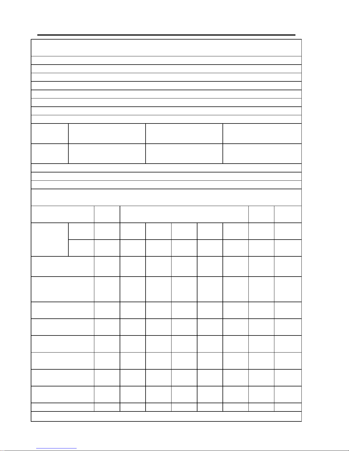
P Series CommissioningPage D.8
CC
CC
C
OMMISSIONINGOMMISSIONING
OMMISSIONINGOMMISSIONING
OMMISSIONING
S S
S S
S
HEETHEET
HEETHEET
HEET
: O : O
: O : O
: O
ILIL
ILIL
IL
Appliance
Serial
No.
:
Burner
Serial
No.
:
High
Fire
Low
Fire
Units
1
Oil
bar or
p
si
Air
mbar or
ins w.
g
.
kg/h or
lb/h
MW or
MJ/h or
Btu/h
% Dry
Basis
% Dry
Basis
ppm Dry
Basis
°C or
°F
°C or
°F
°C or
°F
%
1
Note : Where a choice of measurement units is shown, delete those not applicable
Flue Temp.
Ambient Temp.
Temp. Difference
Efficiency
Heat input
O
2
CO
2
CO
Firing Rate Intermediate Positions
Pressure
at burner
Oil rate
Standing
bar or
p
si
Running
bar or psi
Commissioning Date :
Guarantee Expiry Date :
Fuel Oil Type :
Oil pressure upstream of pump :
Type : Size :
Type : Size :
Site Address :
The details below are to to be completed by the Commissioning Engineer. The completed sheet
must then be
p
hotocopied and a copy forwarded to the appliance manufacturer.
Installer's Name :
Address :
Page 44

Page D.9P Series Commissioning
AAD PFinal\C_Tech\Po\RWF40\D_Comm.pmd 250504A
Page 45

P SeriesPage 10
Page 46

Page E.1
PO Series Operation And Maintenance
E : OPERATION AND MAINTENANCE
Page 47

PO Series Operation And MaintenancePage E.2
NN
NN
N
ORMALORMAL
ORMALORMAL
ORMAL
O O
O O
O
PERAPERA
PERAPERA
PERA
TIONTION
TIONTION
TION
Automatic Modulation
1. Establish the electrical power supply to the
control panel.
2 Ensure that the oil supply is operational at
the correct temperature and pressure
3. Switch on the burner. The burner will go
through the ignition sequence and be
released to modulation under the control of
the RWF40
The burner will now operate normally until :
- It is switched off by the appliance
controls
- It is switched off manually
- There is an elevtrical power failure. In
this event the burner will restart and
run normally whuen power is restored.
No manual intervention is required.
- A failure in any of the safety functions
monitored by the sequence controller.
RR
RR
R
OUTINEOUTINE
OUTINEOUTINE
OUTINE
S S
S S
S
AFETYAFETY
AFETYAFETY
AFETY
C C
C C
C
HECKSHECKS
HECKSHECKS
HECKS
THESE CHECKS SHOULD BE CARRIED OUT
ONLY BY APPROPRIATELY QUALIFIED AND
EXPERIENCED PERSONNEL
Combustion Air
Check that the plant room is well ventilated at all
times and inspect the burner air inlet frequently to
ensure that there is no obstruction to the air flow.
Flame Detector
1. Switch off the burner and the electrical
supply to the control panel
2. Remove the PE cell from the burner casing and
cover the quartz glass envelope to exclude light.
Care should be taken not to touch the glass.
3. Establish the electrical supply to the control
panel and switch on the burner. The burner
should go to lockout at the end of the ignition
cycle.
4. Switch off the burner and the electrical power
supply to the burner. Replace the PE cell.
Establish the electrical supply to the burner and
switch on the burner. Reset the lockout.
Combustion Air Pressure Switch
1. Check that the electrical supply to the control
panel off and that the burner is off.
2. Remove the air pressure switch cover.
3. Fit a manometer or other approved pressure
measuring instrument to the pressure switch
so that the actual measured air pressure can
be compared to the pressure switch dial
setting.
4. Switch on electrical supply to the control
panel. Switch on the burner, allow the burner
to proceed through its sequence until it is
operating at low flame.
5. Slowly turn the adjusting dial on the air
pressure switch clockwise until the flame is
extinguished.
6. The burner will go to lock-out.
7. Turn the dial one division anti-clockwise and
re-set burner lock-out. The burner will then
continue through its cycle until either the start
rate flame is established or burner goes to its
lock-out position.
If the burner goes to lock-out, repeat the
procedure (turning the dial one division) once
per burner cycle until start rate flame is
established.
8. Allow the burner to cycle to low flame and
then turn the adjusting dial a further two
divisions anti-clockwise.
9. Switch off electrical supply to the control
panel and to the burner
10. Replace the air pressure switch cover.
11. Remove the pressure measuring equipment.
RR
RR
R
OUTINEOUTINE
OUTINEOUTINE
OUTINE
M M
M M
M
AINTENANCEAINTENANCE
AINTENANCEAINTENANCE
AINTENANCE
ALWAYS SWITCH OFF THE ELECTRICAL POWER
AND FUEL SUPPLIES TO THE BURNER BEFORE
CARRYING OUT MAINTENANCE.
Combustion Air Fan
Access the fan blades as follows:
1. Remove the ring of nuts on the air inlet side
of the fan unit
2. Remove the plate containing the air inlet.
Page 48

Page E.3
PO Series Operation And Maintenance
Clean the fan blades with a stiff brush, taking care
not to damage them. Inspect the burner air inlet and
ensure that there is no obstruction to the air flow.
Replace the plate and retaining nuts.
Burner Inner Assembly
Air Diffuser
Remove the burner air diffuser plate for inspection
and cleaning as follows: -
1. Remove the PE cell from its holder and secure
to a safe place.
2. Fit the three guide rods through the sockets
on the front plate.
3. Loosen and remove the 4 nuts and washers
securing the backplate to the burner casing.
4. Pull the backplate assembly rearwards,
guiding the inner tube until the diffuser is
clear of the burner head casing
5. Clean the diffuser of any deposits using a
stiff brush.
Ignition Electrodes
Clean and check the electrodes are not cracked or
worn. Renew if necessary.
Check the settings of the ignition electrodes and
reset if necessary, details are shown on Page C.16.
Oil Nozzle
Remove the oil nozzle, dismantle it and wash the
internal filter and other components in a suitable
solvent. Remove any remaining deposits with a clean,
lint-free cloth. The oil nozzle should be replaced after
2000 hours operation.
Re-assemble the inner assemblies in reverse order.
Replace all covers and secure all fittings. The burner
is now ready for operation and remove the guide
rods. Switch on the electrical and fuel supplies to
the burner.
Oil Filters
The oil filter located on top of the preheater should
be removed and cleaned in paraffin or another
suitable solvent.
SAFETY WARNING : CLASS ‘G’ OIL BURNERS
OPERATE WITH OIL AT 140°C FOR
ATOMISATION. THE BURNER SYSTEM SHOULD
BE TAKEN OFF LINE AND ALLOWED TO COOL
BEFORE ATTEMPTING THESE TASKS.
In the case of the cold oil filter, remove the plug
from the sump and drain off any sludge and/or
water present at six-weekly intervals. The cleaning
knob on this filter should be rotated daily. If the
filter fitted in the oil supply line has a disposable
element this should be replaced at least once a
year, more frequently if this is dictated by the
condition of the fuel or other local conditions. If
the filter element is re-usable it should be cleaned
at appropriate intervals. After filter cleaning
operations it will be necessary to remove air from
the system by bleeding the pump.
Oil Preheater
Regular checks should be made to ensure that the
oil temperature is maintained at the correct level
(refer to the table on Page B.8).
FF
FF
F
AA
AA
A
ULUL
ULUL
UL
TT
TT
T
F F
F F
F
INDINGINDING
INDINGINDING
INDING
Any changes made in control settings as a result of
identifying and remedying fault conditions as
described below may necessitate partial or
complete recommissioning. Recommissioning
shall be undertaken only by appropriately qualified
and experienced personnel.
Modulating System
If malfunction of the modulating controller
(RWF40) is suspected, check that only a
compatible pressure/temperature detector has
been used. If problems persist then replacement
of the unit should be considered.
Incorrect Rotation of the Fan Motor
The fan motor rotates in the direction of the arrow
printed on the Nu-way nameplate mounted on the
fan casing. If the direction of rotation is incorrect,
interchange any two phases.
Fan Motor Fails To Start
Check that :
- The electricity supply is available
- The burner is correctly wired
- The fuses are correctly sized and not blown
- The motor overload is not tripped
- The burner controller is not locked out
- The appliance controls are calling for heat
- The oil preheater thermostats and oil
temperature
Page 49

PO Series Operation And MaintenancePage E.4
Fan Motor Starts And Burner Goes To
Lockout
If there is no ignition spark check that:
- The combustion air pressure sensor setting
is correct
- The ignition electrodes are in good condition
and correctly set
- The HT lead is not disconnected or damaged
- The ignition transformer is not faulty
- The burner controller is not faulty
If there is an ignition spark but no start flame check
- The oil supply to the burner
- The oil pump
- The pump
- The pump coupling
- The pump drive motor
- The oil presssure and temperature are in
accordance with the values in the Table on
Page B.8
- The oil valve(s) have opened at the
appropriate time in the sequence
- The filters are clear
- The nozzle is clear
- There is no carbon on the diffuser
Start Flame Failure
Failure of the start flame during the start flame
proving period will cause the sequence controller
to go to lockout. If this occurs check that:
- The glass envelope on the PE Cell is clean
and correctly orientated (it must face towards
the flame)
- The PE Cell and wiring are not faulty
- There is no carbon on the diffuser
- The nozzle is clear
- The flame detector current is adequate and
stable.
- The burner sequence controller is not faulty
- There is sufficient fuel under ignition
conditions to enable the flame to be detected
adequately.
Main Flame Is Not Established
Check that:
- The fuel pressure and flow rate are adequate
- The fuel valves are open at the appropriate
time in the sequence
- The manual isolation valves are open fully
and there are no partial blockages in the
control train
Fan Motor Only Runs Continuously
Check that:
- The air valve positioning motor is correctly
wired and working
SS
SS
S
PP
PP
P
AREARE
AREARE
ARE
P P
P P
P
ARTSARTS
ARTSARTS
ARTS
For spare parts contact Nu-way's Parts And
Components Division at the address and telephone
number listed on the rear cover of this manual. To
avoid delays, please provide the burner model and
serial numbers.
Page 50

Page E.5
PO Series Operation And Maintenance
BB
BB
B
URNERURNER
URNERURNER
URNER
S S
S S
S
ERVICEERVICE
ERVICEERVICE
ERVICE
R R
R R
R
ECORDECORD
ECORDECORD
ECORD
Page 51

PO Series Operation And MaintenancePage E.6
Page 52

Page E.7
PO Series Operation And Maintenance
Page 53

PO Series Operation And MaintenancePage E.8
NN
NN
N
OTESOTES
OTESOTES
OTES
Page 54

Page E.9
PO Series Operation And Maintenance
NN
NN
N
OTESOTES
OTESOTES
OTES
Page 55

PO Series Operation And MaintenancePage E.10
NN
NN
N
OTESOTES
OTESOTES
OTES
Page 56

Enertech Limited,
P O Box 1,
Vines Lane
Droitwich,
Worcestershire,
WR9 8NA
 Loading...