

Page 1

Installation & Maintenance Manual
NDF 35 - 100
Dual Fuel Burner
Page 2

CONTENTS
BURNER AND COMPONENT IDENTIFICATION FOR NDF MODULATING BURNER ............................ 4
BURNER AND COMPONENT IDENTIFICATION FOR NDF TWO STAGE (HIGH/LOW) BURNER ............ 6
INTRODUCTION .............................................................................................................. 9
FEATURES ...................................................................................................................... 9
Burner Capacity .............................................................................................................................. 9
Fuel ................................................................................................................................................. 9
Air Fan Size ................................................................................................................................... 10
Controls and Safety Systems .......................................................................................................... 10
Operating Mode ............................................................................................................................ 10
Burner Type Nomenclature............................................................................................................10
SITE CONDITIONS AND SERVICES ..................................................................................... 10
Flue and Chimney Requirements ...................................................................................................10
Plant Room Ventilation .................................................................................................................. 11
Existing Appliances ........................................................................................................................ 11
Combustion Chamber Conditions .................................................................................................. 11
Gas Supply ....................................................................................................................................11
Gas Boosters..................................................................................................................................11
Oil Supply .....................................................................................................................................13
Electrical Power Supply.................................................................................................................. 13
UNPACKING AND ASSEMBLY ............................................................................................ 13
INSTALLATION ............................................................................................................... 16
BURNER CONTROL AND OPERATION................................................................................. 17
Air Controls ...................................................................................................................................17
Gas Controls .................................................................................................................................. 17
Oil Controls - Twin Pressure Jet Oil Burners ................................................................................... 25
Oil Controls - Single Spill Back Nozzle Oil Burners. ....................................................................... 26
Control Panel ................................................................................................................................ 29
Burner Controller .......................................................................................................................... 36
Flame Monitor............................................................................................................................... 36
Modulating Controller ................................................................................................................... 36
BURNER OPERATING SEQUENCE ....................................................................................... 37
MODULATING CONTROLS ............................................................................................... 38
Controller ...................................................................................................................................... 38
Commissioning Controls. ............................................................................................................... 38
Temperature Detector. ................................................................................................................... 38
Pressure Detector. ......................................................................................................................... 38
General. ........................................................................................................................................38
COMMISSIONING : GENERAL ........................................................................................... 39
Safety And Emergency Notices ..................................................................................................... 39
Inspection ..................................................................................................................................... 39
Initial Settings ................................................................................................................................ 40
COMMISSIONING : OIL .................................................................................................. 40
Burner Dry Run - Twin Pressure Jet Burners (NDFL35-25 to 100-38 Two Stage (High/Low)) ............ 40
Burner Live Run - Twin Pressure Jet Burners (NDFL35-25 to 100-38 Two Stage (High/Low)) ........... 41
Burner Dry Run - Single Spill Back Burners (NDFL Modulating / NDFR - All Models) ...................... 41
Burner Live Run - Single Spill Back Burners (NDFL Modulating / NDFR - All Models) ..................... 42
COMMISSIONING : GAS ................................................................................................. 45
Burner Dry Run - NDFL/R All Models ............................................................................................ 45
Models NDF35 to NDF150Page 2
Page 3

Burner Live Run - NDFL/R All Models ........................................................................................... 46
FINAL COMMISSIONING STAGES - OIL AND GAS ................................................................. 48
Checking the Flame Signal ............................................................................................................. 48
Setting the Air Pressure Switch ....................................................................................................... 48
Modulating Control : Landis & Staefa RWF32 ................................................................................ 49
Final Checks .................................................................................................................................. 50
On Completing Commissioning .....................................................................................................50
FUEL CHANGEOVER PROCEDURE ....................................................................................... 50
Switching From Gas To Oil............................................................................................................. 50
Switching From Oil To Gas............................................................................................................. 51
ROUTINE SAFETY CHECKS ............................................................................................... 51
Combustion Air ............................................................................................................................. 51
Flame Detector .............................................................................................................................51
Valve Proving System (If Fitted) ...................................................................................................... 51
ROUTINE MAINTENANCE................................................................................................. 51
Combustion Air Fan - All Models ................................................................................................... 51
Replacing the Air/Gas Ratio Controller - All Models ........................................................................ 51
Burner Inner Assembly - Twin Pressure Jet Burners ......................................................................... 52
Burner Inner Assembly - Single Spill Back Burners .......................................................................... 52
Oil Filters....................................................................................................................................... 52
Oil Preheater - NDFR Only............................................................................................................ 52
FAULT FINDING ............................................................................................................ 52
Burner Motor Fails To Start............................................................................................................. 53
Fan Starts And Burner Goes To Lockout ......................................................................................... 53
Start Flame Failure ......................................................................................................................... 54
Incorrect Rotation Of Burner Motor ............................................................................................... 54
Main Flame Is Not Established ....................................................................................................... 54
Burner Motor Only Runs Continuously .......................................................................................... 54
SPARE PARTS ................................................................................................................ 54
APPENDIX .................................................................................................................... 55
Burner Head Details ...................................................................................................................... 56
Electrode Setting Detail ................................................................................................................. 58
Performance Envelopes................................................................................................................. 59
Oil Commissioning Sheet............................................................................................................... 62
Gas Commisioning Sheet ............................................................................................................... 63
BURNER SERVICE RECORD ............................................................................................... 64
NOTES ....................................................................................................................... 66
IMPORTANT - SAFETY
It is essential that the following instructions and adjustments are carried out by qualified engineers that
are experienced in forced draught gas and pressure jet oil burner commissioning. In the UK it is a legal
requirement that these engineers must also be CORGI registered. Nu-way cannot be held responsible
for any consequential damage, loss or personal injury as a result of customers failing to follow these
instructions, or as a result of misuse. Your attention is drawn to the Emergency Instructions on Page 39.
EUROPEAN BOILER EFFICIENCY DIRECTIVE (B.E.D.)
All burners and boiler bodies marked separately should comply with EN267 (oil burners) or EN676 (gas
burners) and EN303-1 (boiler bodies).
Burner adjustments must be made in accordance with boiler manufacturersí instructions, and these
must include the flue gas temperature, average water temperature and CO2 or O2 concentration.
Models NDF35 to NDF150
Page 3
Page 4
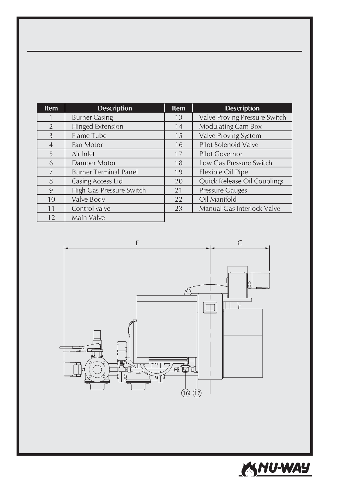
BURNER AND COMPONENT IDENTIFICATION FOR NDF MODULATING BURNER
(MODEL NDF125 SHOWN)
Models NDF35 to NDF150Page 4
Page 5
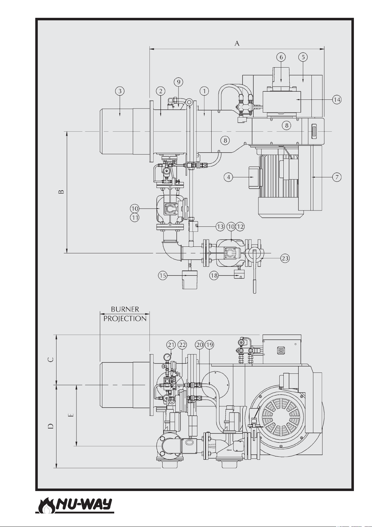
Models NDF35 to NDF150
Page 5
Page 6
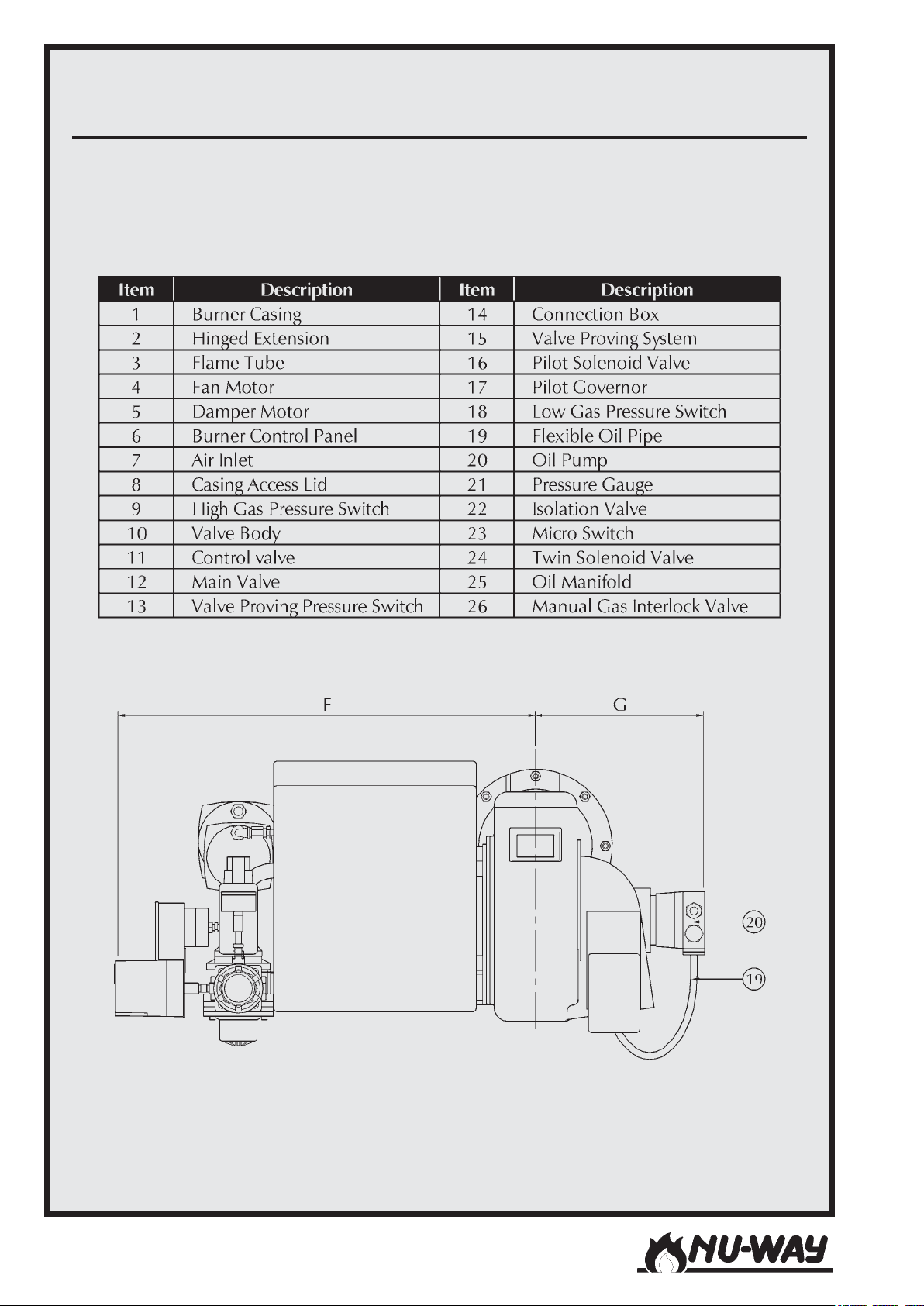
BURNER AND COMPONENT IDENTIFICATION FOR NDF TWO STAGE (HIGH/
LOW) BURNER (MODEL NDF35 SHOWN)
Models NDF35 to NDF150Page 6
Page 7
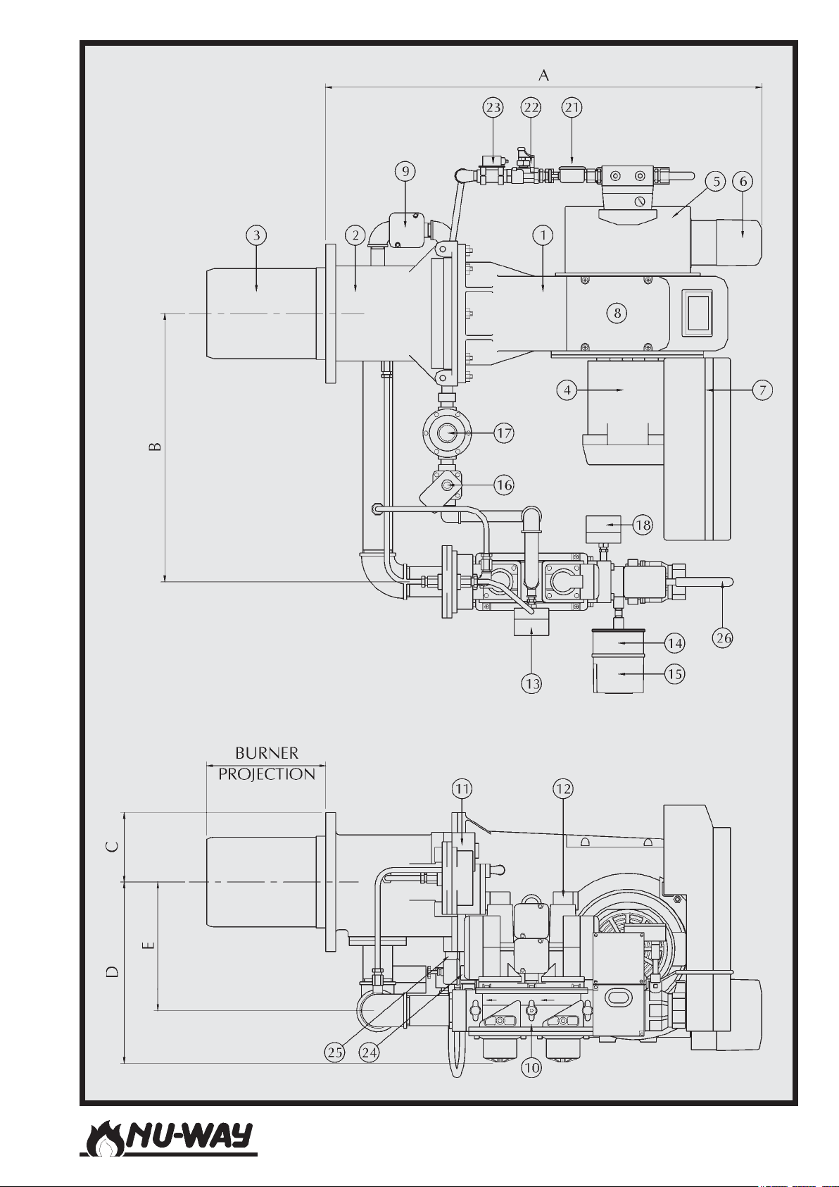
Models NDF35 to NDF150
Page 7
Page 8
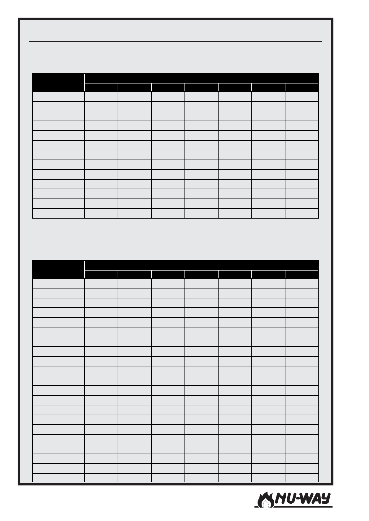
BURNER DIMENSIONS
g
)
Twin Pressure Jet Oil Nozzle Burners
NDFL35-25 to NDFL100-38 Two Stage (Hi/Lo)
Model
NDFL35-25 885 540 165 410 305 686 280
NDFL35-34 1069 540 165 410 305 686 330
NDFL35-38 1081 540 165 410 305 686 330
NDFL50-28 1069 540 165 410 305 800 370
NDFL50-34 1069 540 165 410 305 800 370
NDFL50-38 1081 540 165 410 305 800 370
NDFL60-28 1069 540 165 410 305 800 360
NDFL60-34 1069 540 165 410 305 800 360
NDFL60-38 1081 540 165 410 305 800 360
NDFL80-28 1069 920 165 550 385 1196 360
NDFL80-34 1069 920 165 550 385 1196 360
NDFL85-38 1081 920 165 550 385 1196 360
NDFL100-38 1081 920 165 550 385 1196 372
ABCDE FG
Dimension (All mm)
Single Spill Back Oil Nozzle Burners
NDFR35 to NDFR 150 Two Stage (Sliding Hi/Lo) & Modulatin
NDFL100-41 to NDFL150-44 Two Stage (Sliding Hi/Lo
Model
NDF35-25 810 540 280 410 305 686 210
NDF35-34 967 540 300 410 305 686 260
NDF35-38 1014 540 300 410 305 686 260
NDF50-28 967 540 300 410 305 800 260
NDF50-34 967 540 300 410 305 800 260
NDF50-38 1014 540 300 410 305 800 260
NDF60-28 967 540 300 410 305 800 260
NDF60-34 967 540 300 410 305 800 260
NDF60-38 1014 540 300 410 305 800 260
NDF80-28 967 920 300 550 385 1196 260
NDF80-34 967 920 300 550 385 1196 260
NDF85-38 1014 920 300 550 385 1196 260
NDF100-38 1014 920 300 550 385 1196 260
NDF100-41 1240 920 345 580 416 1196 440
NDF100-44 1240 920 345 580 416 1196 440
NDF125-36 1240 920 345 580 416 1196 440
NDF125-41 1240 920 345 580 416 1196 440
NDF125-44 1240 920 345 580 416 1196 440
NDF150-36 1240 920 345 580 416 1210 440
NDF150-41 1240 920 345 580 416 1210 440
NDF150-44 1240 920 345 580 416 1210 440
ABCDE FG
Dimension (All mm)
Models NDF35 to NDF150Page 8
Page 9
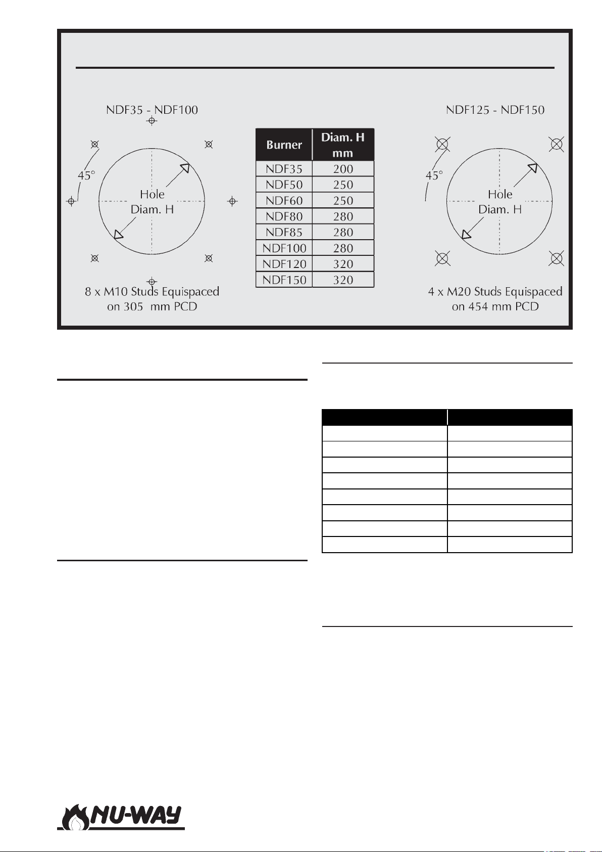
BURNER MOUNTING ARRANGEMENT
INTRODUCTION
This manual has been produced to enable users to
install, commission and use NDF burners safely and
efficiently. At each stage, the conditions that should
be met and the adjustments and other actions that
should be carried out are detailed and the locations of the various components and adjustment
mechanisms are identified. Where appropriate, this
information is supported by tables and graphs. Literature on the proprietary components used in
NDF burner systems is available on request.
FEATURES
Developed through extensive field experience in
the UK and overseas markets, the NDF series of
dual fuel burners meets all current test authority
requirements in these markets and sets new standards in efficient and reliable operation.
NDF burners are designed for flange mounting to
the appliance front plate and they are delivered
ready to install with a pre-wired packaged control
system and plug-in gas train.
Burner Capacity
The figures quoted are nominal burner outputs
based on the gross calorific value.
Burner Model Capacity (kW)
NDF35 583 - 1019
NDF50 1000 - 1500
NDF60 1500 - 1850
NDF80 1640 - 2360
NDF85 1840 - 2450
NDF100 1800 - 3000
NDF125 2950 - 3700
NDF150 3600 - 4500
Please refer to the Appendix of this handbook for
detailed burner performance data.
Fuel
Burners designated NDFL are suitable for light distillate oil (Class D) and those designated NDFR are
suitable for residual oils (Classes E, F and G). All
NDF burners are normally configured for natural
gas but versions suitable for liquefied petroleum
gas (LPG) or manufactured gas (towns gas) can be
supplied on request.
Models NDF35 to NDF150
Page 9
Page 10
Air Fan Size
To match NDF burners with the appliance, with
respect to both burner output and appliance resistance, a number of combustion air fan sizes are
available for each model as detailed in the table
below.
Burner Model Available Fan Sizes
NDF35 25, 34 & 38
NDF50 28, 34 & 38
NDF60 28, 34 & 38
NDF80 28 & 34
NDF85 38
NDF100 38, 41 & 44
NDF125 36, 41 & 44
NDF150 36, 41 & 44
The fan size quoted is the diameter of the fan
impellor (measured in cm) and appears as a suffix
to the model number. For example, a burner designated NDFR60 - 34 is a model 60 for residual
fuel oil firing with a 34 cm diameter combustion
air fan impellor.
Controls and Safety Systems
NDF burners are fitted with a combustion airflow
control and an air/fuel ratio control system which
together ensure smooth starting and optimum operating efficiency.
An air pressure switch provides safe burner shutdown if the combustion air supply becomes insufficient for complete combustion. The burner's additional safety systems include for gas pressure
monitoring (low and high) whilst gas firing, and
low oil temperature monitoring (NDFR) whilst firing on fuel oil. Continuous flame supervision is
provided by an ultraviolet (UV) cell and automatic
programming control unit.
Operating Mode
Standard NDF burners are manufactured for either fully modulating or two-stage (high/low) operation on both fuels. A special variation of the
NDFL35 to NDFL100-38 burner is available upon
request, designated Modulating - High/Low. In this
version, the burner operates in fully modulating
mode when firing on gas, and 2 stage (high/low)
mode when firing on oil.
Oil Firing
Fully Modulating Operation
All NDF burners manufactured for fully modulating operation use a single spillback oil nozzle.
If the burner has been correctly matched to the
appliance, a turndown ratio of up to 3.0:1 may be
achieved.
Two Stage Operation
NDFL burners up to and including the NDFL100 38 use twin simplex oil nozzles, one for low fire
and both for high fire.
The oil nozzles are sized to give a turndown ratio
of between 1.8 and 2.0:1.
NDFL burners NDFL100 - 41 and larger, together
with all NDFR burners are supplied with a system
designated 'Sliding High/Low' which uses a single
spillback oil nozzle (similar to that employed in
the fully modulating mode) which is constrained
to operate at either of two fixed oil flows corresponding to the high and low fire rates. If the burner
has been correctly matched to the appliance, a
turndown ratio of up to 3.0:1 may be achieved.
Gas Firing - All Modes
When gas firing, the fuel gas flow is controlled by
an automatic valve which, following commissioning, precisely matches the fuel flow to the air flow
to achieve the required fuel/air ratio at any point
in the full turndown range. If the burner has been
correctly matched to the appliance, a turndown
ratio between 2.0 and 2.5:1 may be achieved.
Burner Type Nomenclature
NDF burners are divided into two groups, depending on the oil nozzle employed:
Twin Pressure Jet Burners
Comprising two stage NDFL burners up to
and including the NDFL100 - 38
Single Spill Back Burners
Comprising two stage NDFL burners
NDFL100 - 41 and larger,
all fully modulating NDFL burners,
all two stage NDFR burners,
all fully modulating NDFR burners.
Throughout this handbook the burners are referred
to by this grouping.
SITE CONDITIONS AND SERVICES
Flue and Chimney Requirements
It is important that:
Models NDF35 to NDF150Page 10
Page 11

- The flue pipe from the appliance and the joint
between this flue and the chimney are sealed
to prevent leakage of combustion products.
- The flue pipe from the appliance does not
protrude into the chimney beyond the inside wall.
- The top of the flue or chimney shall be higher
than any roof within a radius of 10 metres.
- Checks are made to ensure that the chimney is suitable for gas and oil fired appliances
and that the proposed installation complies
with all Local Authority and other regulations
covering such installations.
- The flue must be balanced at the appliance
outlet.
- If more than one appliance is connected to
a common flue or chimney, the cross-section of this flue or chimney should be adequate for the total volume of combustion
products from the appliances.
Plant Room Ventilation
The burner must be supplied with dust free air at
sufficient rates for all firing conditions, in accordance with the appropriate Standards.
Existing Appliances
The appliance should be prepared for installation
of the NDF burner by thorough cleaning, including the removal of all adhering tar, scale and dirt.
An inspection should also be carried out to ensure
that the appliance is in good condition. Any doubt
about the suitability of the appliance for dual fuel
firing should be referred to the appliance manufacturer.
Combustion Chamber Conditions
When the burner is fitted to an appliance designed
to work under balanced or negative combustion
chamber pressure conditions the over-fire draught
must not exceed 0.25 mbar.
It is essential that a 90∞ manual isolation valve is
fitted upstream of the gas control train to allow
the burner to be isolated for maintenance. The
size of this valve should not be less than that of the
burner control train in order to avoid any restriction in gas flow.
Gas Boosters
When a gas booster is used, the gas pressure at
the booster inlet must not fall below 10 mbar under any conditions. A low gas pressure switch must
be fitted on the upstream side of the booster to
prevent it starting if the supply pressure is insufficient.
An additional pressure switch should be used to
monitor the pressure downstream of the booster
and prevent the burner going to high fire if the
pressure is insufficient.
It should be noted that CE marked burners fitted
with a low gas pressure switch will not run if the
gas pressure from the booster is insufficient. This is
due to the low gas switch being set to safegaurd
combustion quality at the high fire setting. In this
situation the booster outlet pressure switch will
have no bearing on the burner control, but can be
used to indicate booster failure
The booster should be installed as near to the
burner as possible. It should be positioned on a
firm, flat, horizontal surface using anti-vibration
mountings. All connecting pipework should be well
supported and accurately positioned in order to
avoid stressing the booster casing. Flexible connectors, which reduce both pipework stresses and
transmitted noise, must be fitted. The gas supplier
should be asked to recommend the size of
pipework between the meter and the booster to
ensure that the required pressure and flow are
available.
Gas Supply
The gas supply pipework to the burner must be
appropriate to local conditions and must be constructed and installed in compliance with appropriate Codes and Standards. It shall be of sufficient
size to satisfy the pressure and volume flow requirements of the burner under all firing conditions. Checks should be made to ensure that all
meters and other components are appropriately
rated for the maximum gas flow rate anticipated.
Models NDF35 to NDF150
Page 11
Page 12
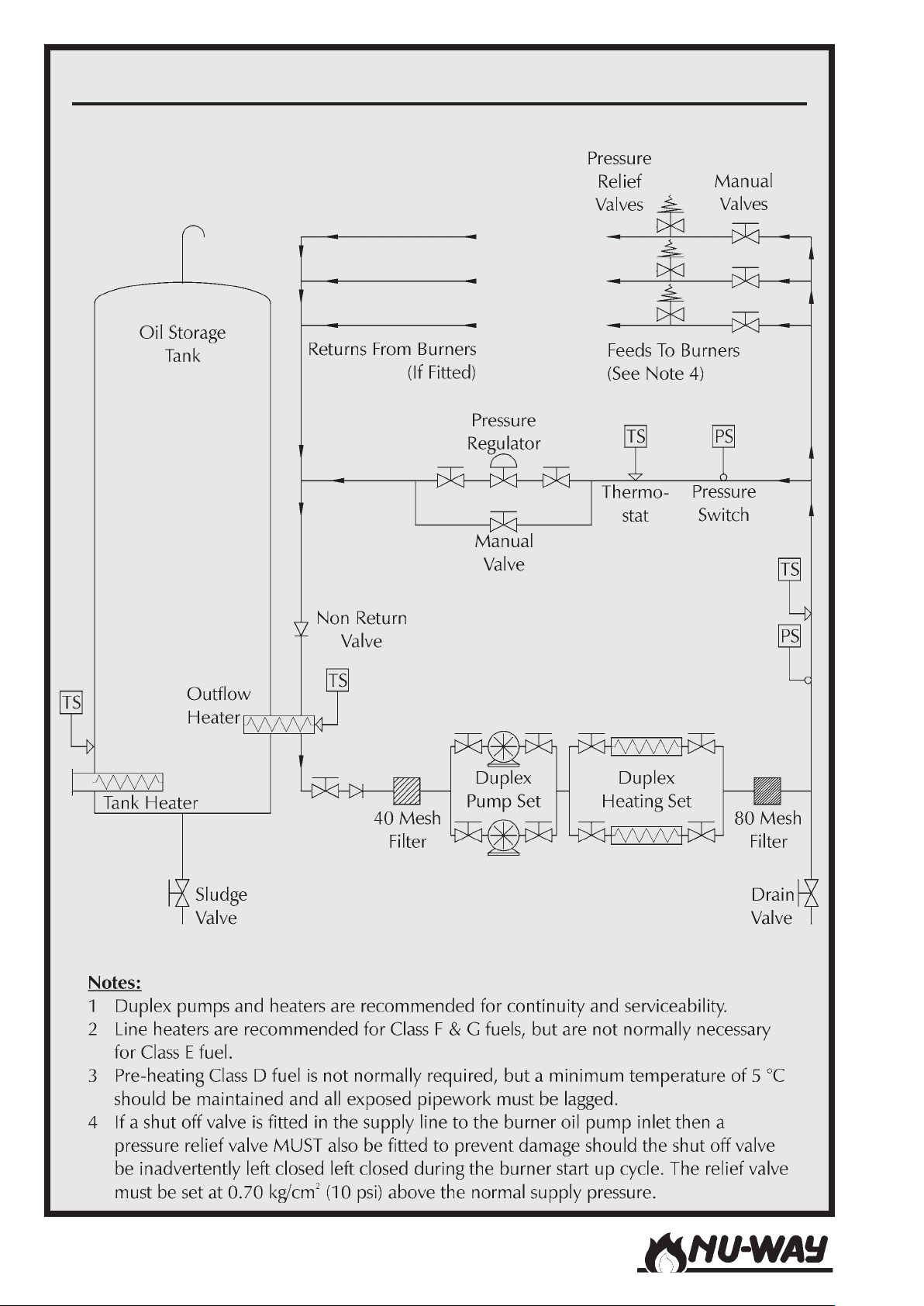
A TYPICAL PUMPED OIL RING MAIN
Models NDF35 to NDF150Page 12
Page 13
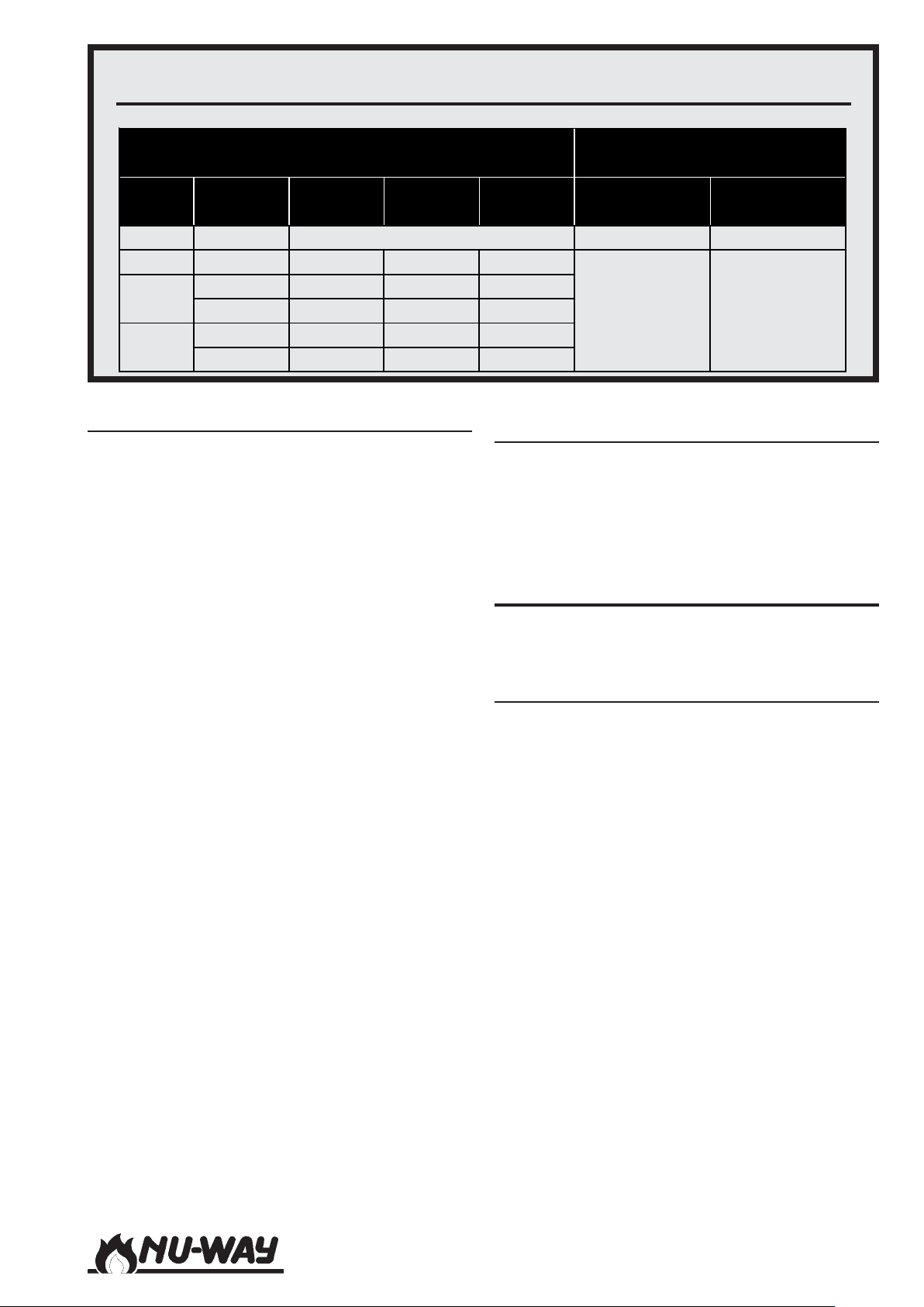
OIL HANDLING TEMPERATURES AND PRESSURES
p
Fuel Handling Temperatures (°C)
Fuel
Class
D 35 0.35 to 0.70 72.5 Max
E 200 16 16 82
F
G
Viscosity
(Seconds)
960 30 43 110
1500 36 65 118
3500 50 82 132
4200 55 86 140
Minimum
From Tank
Minimum 5 Recommended
Burner
Inlet
Oil Supply
The oil supply pipework to the burner must be
appropriate to local conditions and must be constructed and installed in compliance with appropriate Codes and Standards. It shall be of sufficient
size to satisfy the pressure and volume flow requirements of the burner under all firing conditions. Checks should be made to ensure that all
meters and other components are appropriately
rated for the maximum oil flow rate anticipated.
Galvanised steel pipe should not be used. The supply pipework should include an appropriate filter.
The final connection to the oil pump inlet port
should be made using the flexible pipes supplied
with the burner.
NDFL burners may employ a pumped ring main
or a gravity feed oil supply system.
Where a gravity feed system is used it should be
designed and sized such that the oil pressure at
the pump inlet is not less than 350 mbar and not
more than 689 mbar. A two-pipe system must be
used. It is important to ensure that the return pipe
is not obstructed as this may result in damage to
the pump.
Where it is thought desirable, a pumped ring main
(refer to the schematic diagram on Page 12) of appropriate capacity may be used for NDFL burners
and such a system is essential where the burner is
to operate on residual oil (NDFR burners). The capacity of the ring main pump should be at least
1.25 times that of the burner pump(s) that it is required to supply. In the case of NDFR burners the
pipework and oil storage tank should be insulated,
trace heated and thermostatically controlled in accordance with the data shown in the table on Page
13.
Fuel Delivery Pressures
Atomising
(At Inlet To Burner Oil Pum
2
kg/cm
4 to 5 57 to 71
psi
)
Electrical Power Supply
A 400 Volt, three-phase 50 Hz supply is required.
Power requirements are listed in the Tables on
Pages 14, 15 and 16. The power supply provided
must comply with all relevant Codes and Standards.
UNPACKING AND ASSEMBLY
To safeguard against damage in transit, NDF burners are supplied in partly assembled form.
Twin Pressure Jet Burners
(NDFL35-25 to 100-38 2 Stage (High/Low))
NDFL burner systems comprise two units:
- The burner body, complete with control
package, hinged extension and flame tube
assembly.
- The gas control train.
To assemble the burner:
- Fit the gas control train to the burner body
using the gasket supplied, ensuring that the
gasket is fitted correctly with all holes corresponding with those on the burner flange.
- Connect the combustion air impulse pipe
from the SKP70 air/gas ratio controller to the
left side of the hinged extension.
- Connect the multi-pin plug on the gas valve
train to the socket on the rear of the control
package.
Note: In some circumstances it may be advisable
to fit the burner casing to the appliance before
attaching the gas control train. It is recommended
that lifting gear should be employed if necessary.
Models NDF35 to NDF150
Page 13
Page 14
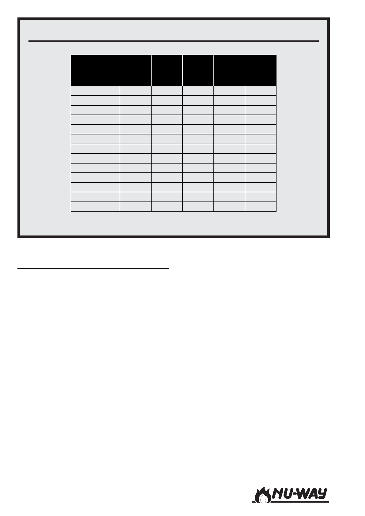
ELECTRICAL POWER REQUIREMENTS : TWIN PRESSURE JET OIL BURNERS
(NDFL35-25 to NDFL100-38 Two Stage Operation)
Fan
BURNER
NDFL35-25 1.1/1.5 15.8 2.7 1.0 10
NDFL35-34 2.2/3.0 29.3 5.0 1.5 16
NDFL35-38 3.0/4.0 38.6 6.6 2.5 20
NDFL50-28 2.2/3.0 29.3 5.0 1.5 16
NDFL50-34 3.0/4.0 38.6 6.6 2.5 20
NDFL50-38 4.0/5.5 49.7 8.5 2.5 25
NDFL60-28 2.2/3.0 29.3 5.0 1.5 16
NDFL60-34 4.0/5.5 49.7 8.5 2.5 25
NDFL60-38 4.0/5.5 49.7 8.5 2.5 25
NDFL80-28 3.0/4.0 38.6 6.6 2.5 20
NDFL80-34 4.0/5.5 49.7 8.5 2.5 25
NDFL85-38 5.5/7.5 66.1 11.3 2.5 32
NDFL100-38 7.5/10.0 88.9 15.2 4.0 32
NOTE: All above burner fan motors are started D.O.L.
Motor
kW/hp
Start
Current
A/Phase
FLC
A/Phase
Cable
Size
(mm2)
HRC
Fuse
(A)
Single Spill Back Burners
(NDFL Modulating Burners, NDFR Burners)
NDFR burner systems comprise four units:
- The burner body, complete with hinged extension and flame tube assembly.
- The gas control train.
- The oil pump unit (NDFL).
- The oil pumping and heating unit (NDFR).
- A free-standing or wall mounted control
panel.)
To assemble the burner:
- Fit the gas control train to the burner body
using the gasket supplied, ensuring that the
gasket is fitted correctly with all holes corresponding with those on the burner flange.
- Connect the combustion air impulse pipe
from the SKP70 air/gas ratio controller to the
left side of the hinged extension.
- Connect the multi-pin plug on the gas valve
train to the socket on the rear of the burner
mounted terminal panel.
- Place and secure the oil pump/pumping and
heating unit in the desired position. The floor
mounting arrangements are shown on Page
32 (residual fuels) and Page 33 (distillate fuels). Connect the unit to the burner pipework
using the flexible connectors provided.
- Fix the control panel in an appropriate position and make the electrical connections to
the burner package and oil pump unit, as
shown in the wiring diagram contained in
the instruction pack attached to the burner.
Note: In some circumstances it may be advisable
to fit the burner casing to the appliance before
attaching the gas control train. It is recommended
that lifting gear should be employed if necessary.
Models NDF35 to NDF150Page 14
Page 15
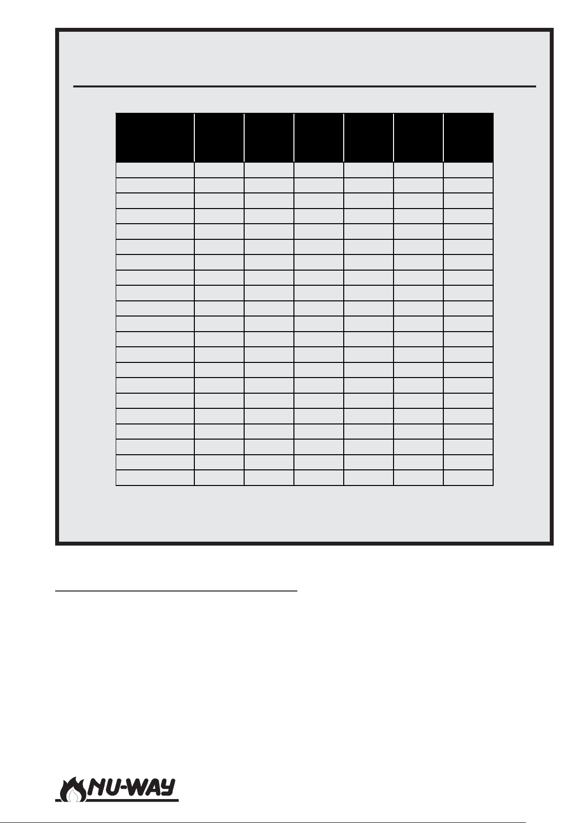
ELECTRICAL POWER REQUIREMENTS : SINGLE SPILL BACK NOZZLE DISTILLATE
OIL BURNERS
(NDFL35-25 to NDFL150-44 Modulating and Two Stage Operation)
Fan
BURNER
NDF35-25 1.1/1.5 0.55/0.75 25.2 4.3 1.5 16
NDF35-34 2.2/3.0 0.55/0.75 38.6 6.6 2.5 20
NDF35-38 3.0/4.0 0.55/0.75 48.0 8.2 2.5 25
NDF50-28 2.2/3.0 1.1/1.5 45.0 7.7 2.5 25
NDF50-34 3.0/4.0 1.1/1.5 54.4 9.3 4.0 32
NDF50-38 4.0/5.5 1.1/1.5 65.5 11.2 4.0 32
NDF60-28 2.2/3.0 0.75/1.0 41.0 7.0 2.5 25
NDF60-34 4.0/5.5 0.75/1.0 61.5 10.5 4.0 32
NDF60-38 4.0/5.5 0.75/1.0 61.5 10.5 4.0 32
NDF80-28 3.0/4.0 0.75/1.0 50.4 8.6 2.5 25
NDF80-34 4.0/5.5 0.75/1.0 61.5 10.5 4.0 32
NDF85-38 5.5/7.5 0.75/1.0 77.9 13.3 4.0 32
NDF100-38 7.5/10.0 1.5/2.0 101.3 17.3 4.0 40
NDF100-41 11.0/15.0 1.5/2.0 97.0 25.3 6.0 40
NDF100-44 11.0/15.0 1.5/2.0 97.0 25.3 6.0 40
NDF125-36 7.5/10.0 1.5/2.0 101.3 17.3 4.0 40
NDF125-41 11.0/15.0 1.5/2.0 97.0 25.3 6.0 40
NDF125-44 11.0/15.0 1.5/2.0 97.0 25.3 6.0 40
NDF150-36 11.0/15.0 1.5/2.0 97.0 25.3 6.0 40
NDF150-41 11.0/15.0 1.5/2.0 97.0 25.3 6.0 40
NDF150-44 15.0/20.0 1.5/2.0 123.6 32.9 10.0 50
Motor
kW/hp
Pump
Motor
kW/hp
Start
Current
A/Phase
FLC
A/Phase
Cable
Size
(mm
HRC
Fuse
2
)
(A)
NOTE: Burner fan motors up to and including 7.5 kW are started D.O.L.
Special Compact Burner Arrangement
Depending on the burner model and application,
a special compact version of NDFL Modulating and
NDFR burners can be supplied. These burner
models are supplied to special order only and are
delivered with the oil pumping (pumping and heating) equipment mounted under the burner throat.
If additional appliance control requirements are
not specified, then the burner control panel can
also be burner mounted. The equipment is thus
delivered as a packaged arrangement with all of
the interconnecting oil pipework and electrical
control connections pre-made. The gas control
train will be supplied loose.
IMPORTANT: - The NDF compact burner, in par-
ticular the NDFR series, will be heavier than its
standard counterpart. This must be taken into consideration when fitting the burner to the appliance.
It is strongly recommended that lifting gear should
be employed when carrying out this task.
Models NDF35 to NDF150
Page 15
Page 16
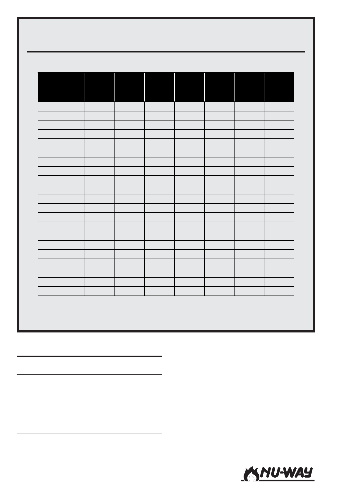
ELECTRICAL POWER REQUIREMENTS : SINGLE SPILL BACK NOZZLE RESIDUAL
OIL BURNERS WITH OIL PRE-HEATER
(NDFL35-25 to NDFL150-44 Modulating and Two Stage Operation)
Pump
BURNER
NDF35-25 1.1/1.5 31.6 14.0 4.0 32.0 6.0 1.5
NDF35-34 1.1/1.5 45.0 16.4 4.0 32.0 6.0 1.5
NDF35-38 1.1/1.5 54.4 18.0 4.0 40.0 6.0 1.5
NDF50-28 1.1/1.5 45.0 18.5 4.0 40.0 7.5 1.5
NDF50-34 1.1/1.5 54.4 20.1 4.0 40.0 7.5 1.5
NDF50-38 1.1/1.5 65.5 22.0 4.0 40.0 7.5 1.5
NDF60-28 1.1/1.5 45.0 18.5 4.0 40.0 7.5 1.5
NDF60-34 1.1/1.5 65.5 22.0 4.0 40.0 7.5 1.5
NDF60-38 1.1/1.5 65.5 22.0 4.0 40.0 7.5 1.5
NDF80-28 1.5/2.0 59.7 21.0 4.0 40.0 7.5 1.5
NDF80-34 1.5/2.0 70.8 22.9 4.0 40.0 7.5 1.5
NDF85-38 1.5/2.0 87.2 25.7 6.0 40.0 7.5 1.5
NDF100-38 1.5/2.0 101.2 28.1 6.0 40.0 7.5 1.5
NDF100-41 1.5/2.0 97.0 36.1 10.0 50.0 7.5 1.5
NDF100-44 1.5/2.0 97.0 36.1 10.0 50.0 7.5 1.5
NDF125-36 1.5/2.0 101.2 30.3 6.0 40.0 9.0 2.5
NDF125-41 1.5/2.0 97.0 38.3 10.0 50.0 9.0 2.5
NDF125-44 1.5/2.0 97.0 38.1 10.0 50.0 9.0 2.5
NDF150-36 1.5/2.0 97.0 42.7 10.0 63.0 12.0 4.0
NDF150-41 1.5/2.0 97.0 42.7 10.0 63.0 12.0 4.0
NDF150-44 1.5/2.0 123.7 50.3 16.0 80.0 12.0 4.0
Motor
kW/hp
Start
Current
A/Phase
FLC
A/Phase
Cable
Size
(mm2)
HRC
Fuse
(A)
Pre-
heater
kW
Cable
Size
(mm2)
NOTE: Burner fan motors up to and including 7.5 kW are started D.O.L. Above 7.5
INSTALLATION
General
Ensure that the appliance is suitable for the heat
input of the burner. If there is any doubt in this
area reference should be made to the appliance
manufacturer. Detailed burner performance data
are presented in the Appendix of this handbook.
Fitting to the Appliance
If the burner is to be fitted to a new appliance,
refer to the appliance manufacturer's recommendations.
Models NDF35 to NDF150Page 16
If the burner is to be fitted to an existing appliance, a mounting flange must be provided as detailed in the Section on Burner and Components
Identification. Ensure that the joint between the
burner and the mounting flange is sealed effectively using the gasket provided.
The flame tube should be flush with the inner face
of the appliance combustion chamber. Up to 10
mm protrusion may be acceptable (refer to the
appliance manufacturer) however it is not generally permissible for the flame tube to sit within the
appliance firing tunnel.
Page 17

Special extensions may be specified by the appliance manufacturer, for example in the case of a
reverse flame boiler.
Electrical Power Connection
Connect a three-phase, 50 Hz electrical supply to
the burner, observing all applicable Codes and
Standards. The electrical connections required are
shown in the wiring diagram contained in the instruction pack attached to the burner. These diagrams also show the external auxiliary control connections which must be made.
If the burner is supplied as part of a packaged appliance/burner unit, refer to the appliance manufacturer's instructions.
BURNER CONTROL AND OPERATION
All personnel concerned with commissioning and/
or operation of NDF burners should familiarise
themselves with the information presented in this
Section.
Single Spill Back Burners.
The single spill back burners employ a Landis &
Staefa SQM 10 motor as shown on Page 19. This
motor activates the damper through an adjustable
cam and cable system, and is mounted above the
air inlet on all models.
Air Diffuser
The air diffuser is fitted to the front of the burner
assembly, within the flame tube (refer to the Appendix). This diffuser controls the combustion air
flow and creates a pressure drop across the burner
head, promoting good fuel/air mixing and flame
stability.
Air Pressure Switch
The air pressure switch is located on the left side
of the burner casing. Its function is to ensure that
combustion air flow is adequate under all operating conditions.
Air flow failure at any stage beyond the first few
seconds of the pre-purge sequence will result in
burner lockout.
Air Controls
Air Regulator
NDF 35-25 to NDF 100-38.
The flow of combustion air into the burner is controlled by a single adjustable air damper blade located within the air damper casting on the right
hand side (in all cases, such descriptions refer to
the system as viewed from the rear) of the burner.
NDF 100-41 to NDF 150-44.
The flow of combustion air into the burner is controlled by a multiple-aperture rotary type damper,
fitted to the burner casing within the air inlet silencer on the right hand side of the burner.
Air Damper Motor
In all cases, the air damper is controlled by a servomotor containing adjustable limit switches for
the low and high fire positions.
Twin Pressure Jet Burners.
On twin pressure jet burners a Berger Lahr STM 6
5 cam motor is used, as shown on Page 18. A fully
closed position is provided to prevent air flowing
through the appliance when the burner is not in
operation. On these burners the servomotor is
mounted on the rear face of the air inlet and directly coupled to the air damper blade.
Gas Controls
A typical gas train fitted is shown on Page 20.
Gas Nozzle
NDF burners utilise a spiked head design with
multiple gas tubes fitted with appropriately sized
gas restrictors. Referred to as the "gas nozzle" this
is fitted to the front of the burner assembly, within
the flame tube (refer to the Appendix). The number
and diameter of the gas tubes in this nozzle are
specified in accordance with the rating of the
burner and the gas to be used (refer to the table in
the Appendix).
High Gas Pressure Switch
A high gas pressure switch is fitted at the outlet of
the gas train to ensure that any increase in gas supply pressure above the level needed to maintain
the set conditions results in a safe burner shutdown.
In most cases, high gas pressure would indicate a
fault with the air/gas ratio controller.
The pressure switch, which is fitted with an illuminated fault indicator and manual reset button, is
factory set to the maximum value. Final adjustment
of the setting of this switch is described in the Section on Commissioning.
Models NDF35 to NDF150
Page 17
Page 18
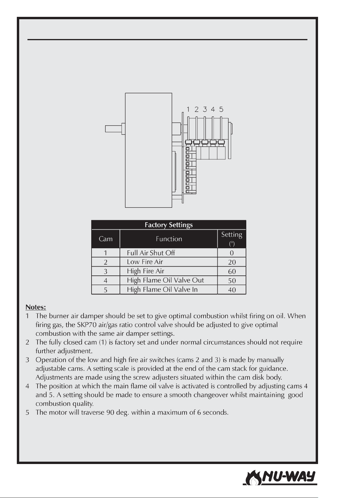
AIR DAMPER SERVOMOTOR : TWIN PRESSURE JET BURNERS
Model : Berger Lahr STM 6
Models NDF35 to NDF150Page 18
Page 19
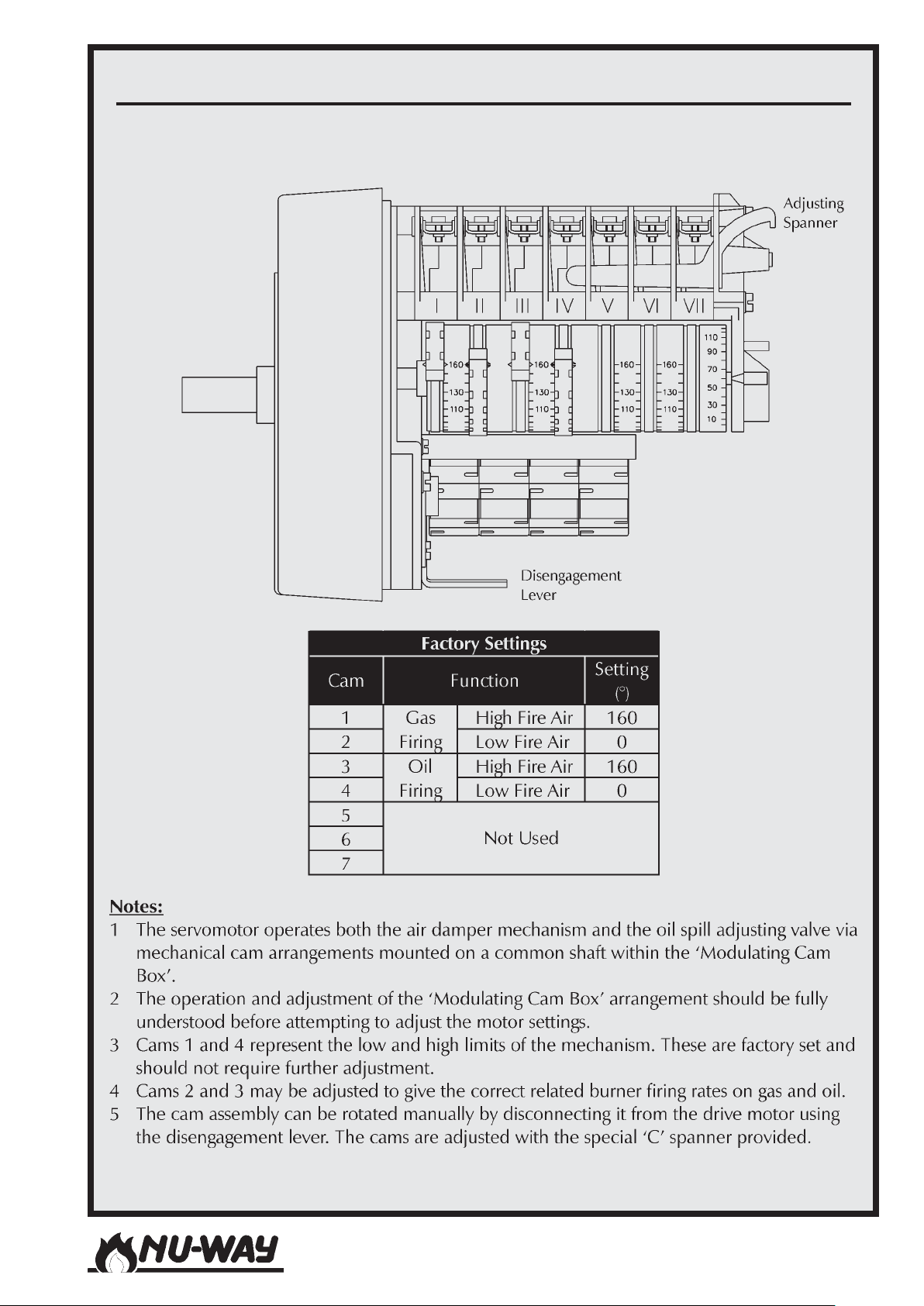
AIR DAMPER SERVOMOTOR : SINGLE SPILL BACK NOZZLE BURNERS
Model : Landis & Staefa SQM 10
Models NDF35 to NDF150
Page 19
Page 20
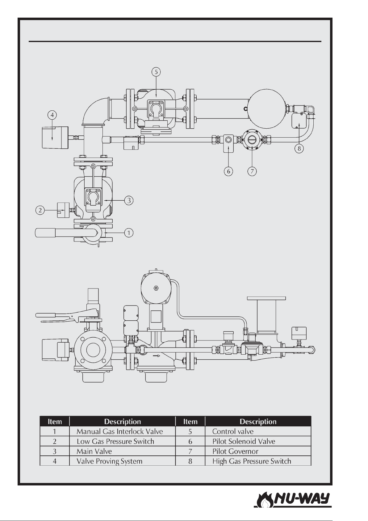
TYPICAL GAS TRAIN
Models NDF35 to NDF150Page 20
Page 21
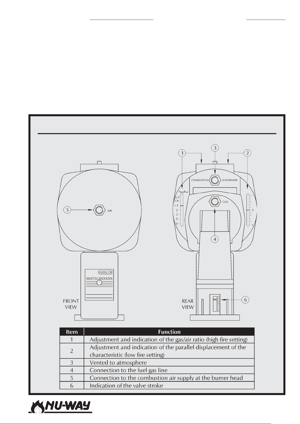
Low Gas Pressure Switch
Provision of a low gas pressure switch is required
by European Standard EN 676 - Automatic forced
draught burners for gaseous fuels. This pressure
switch is fitted to all burners which carry the CE
marking but it may not be fitted to non-CE marked
burners.
The low gas pressure switch monitors inlet gas pressure and ensures that any decrease in gas pressure
below the value needed to maintain satisfactory
combustion results in a safe burner shutdown. Final adjustment of the setting of this switch is described in the Section on Commissioning.
GAS CONTROL VALVE (SKP 70)
Gas Valve Train
In addition to the pressure switches noted above,
the gas control train includes an air/gas ratio controller, automatic safety shut-off valves and a governor in the start gas line. A manual isolation valve,
which must be fitted and wired during installation
at the inlet to the gas train, is electrically interlocked
to the burner control circuit. This valve must be in
the closed position when firing the burner on oil.
Models NDF35 to NDF150
Page 21
Page 22

SKP70 Air/Gas Ratio Controller
The air/gas ratio controller, shown on Page 21 varies the gas pressure in response to changes in combustion air pressure to ensure that the air/gas ratio
remains constant over the operating range of the
burner.
A separate gas pressure governor is not necessary.
Two impulse pipes (both factory supplied) are connected to the air/gas ratio controller.
The first is connected to the burner hinged extension and supplies air pressure to the ratio controller. Note that in installations with negative air pressure in the combustion chamber, this pipe must
always be under positive pressure. A second pipe
connected to the gas line downstream of the valve
set provides gas pressure to the ratio controller.
SKP70 combustion chamber impulse connection
The impulse connection to the combustion cham-
ber is not required in the majority of applications
and is therefore not supplied as part of the burner
package.
This is because the resistance of the combustion
chamber / flue assembly is assumed to remain constant and that the pressure within this chamber
will change in proportion to the burner gas and
combustion air pressure (as the burner output
changes).
If however the pressure in the combustion chamber does not change in proportion to the burner
gas or air pressure, i.e. the plant is fitted with a
flue gas fan, continuously operating flue gas damper
or the combustion chamber pressure changes from
negative to positive whilst moving from Low to High
flame, then a compensating circuit is required.
This means that the pressure in the combustion
chamber must be connected to the SKP70 so that
the controller can automatically offset the pressure changes.
This compensating circuit should also be used if
pressure shocks and vibrations, which adversely
affect burner start up, develop in the combustion
chamber during the start up phase.
Naturally, it must always be taken into consideration that the burner output decreases as the pressure in the combustion chamber increases, and
visa versa.
Installation of combustion chamber impulse pipe
A minimum inside pipe diameter of 8mm is rec-
ommended.
The impulse pipe should be as short as possible to
allow the controller to respond quickly to sudden
burner output changes. It must be installed such
that the gases will cool down in the area of the
impulse pipe and condensing gases will not enter
the controller but run back into the combustion
chamber. If necessary, a water trap must be provided.
Valve Proving System
Valve proving systems, as shown schematically on
Pages 23 and 24 are standard on all NDF burners
with maximum firing rates which exceed 1200 kW.
The standard model fitted is the Landis & Staefa
LDU 11 (see Page 23) but the Dungs VPS 504 (see
Page 24) is available as an option.
When the burner operating sequence is initiated,
the burner control box energises the proving system, which then carries out the following checks.
Landis & Staefa LDU11
The LDU11 control unit is designed to provide auto-
matic gas valve proving (leakage test) based on the
pressure proving principle.The system comprises the
control unit, which is fixed to a bracket / terminal
box assembly close to the main valve block, and a
dual pressure switch which is connected to the test
space between the main valves. The unit comes prewired as part of the gas train harness.
Gas valve proving is initiated automatically upon completion of the burner control circuit prior to burner
start up. The proving test is based on the 2-stage pressure proving principal. First, the main safety valve (V1)
on the upstream side of the gas circuit is tested by
evacuating the test space (via the pilot valve V3) and
by monitoring the atmospheric pressure in it, then
the valves (V2 and V3) on the burner side are tested
by pressurising the test space and monitoring the gas
pressure. If the pressure increases excessively during
the first test phase (TEST 1) or decreases excessively
during the second test phase (TEST 2), the control
unit inhibits burner start up and goes to lockout. The
lockout reset button lights up and signals a fault.
A programme indicator, which stops whenever a fault
is signalled, indicates which valve(s) set is leaking.
The control unit requires to be reset manually, either
on the unit itself or by a remote resetting if this has
been fitted.
Dungs VPS504
The VPS504 is a self-contained unit that operates on
the pressure build up principle. The unit is only suitable for use on valve line sizes up to and including 2"
(DN50).
Models NDF35 to NDF150Page 22
Page 23
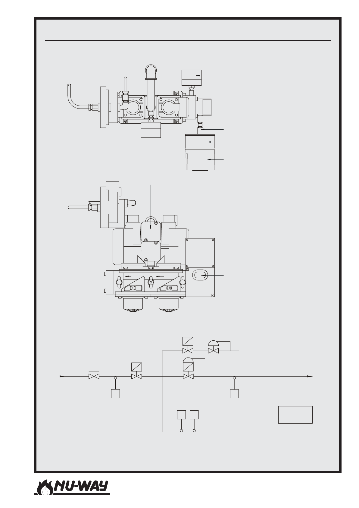
VALVE PROVING SYSTEM : LDU 11
S
(Standard Fitting)
Dual Gas Pressure
Switch Assembly
(’Mini-Maxi’)
Low Gas
Pressure Switch
Mounting Bracket
Terminal Box
LDU11 Control Unit
Schematic:
Manual Gas
Valv e With
Electrical
Interlock
Gas Inlet
Start Gas
Val ve (V3)
Main Gas
Val ve (V1)
Combined Main Valve
PS PS
Low Gas
Pressure Switch
Mini-Maxi Pressure
And Governor (V2)
PS PS
Start Gas
Governor
witches
Control Position Indicator,
‘Gas Proving Failed’ Neon and
Programme Reset Button
To B u rn e r
High Gas
Pressure Switch
Electrical
Connection
LDU 11
Models NDF35 to NDF150
Page 23
Page 24
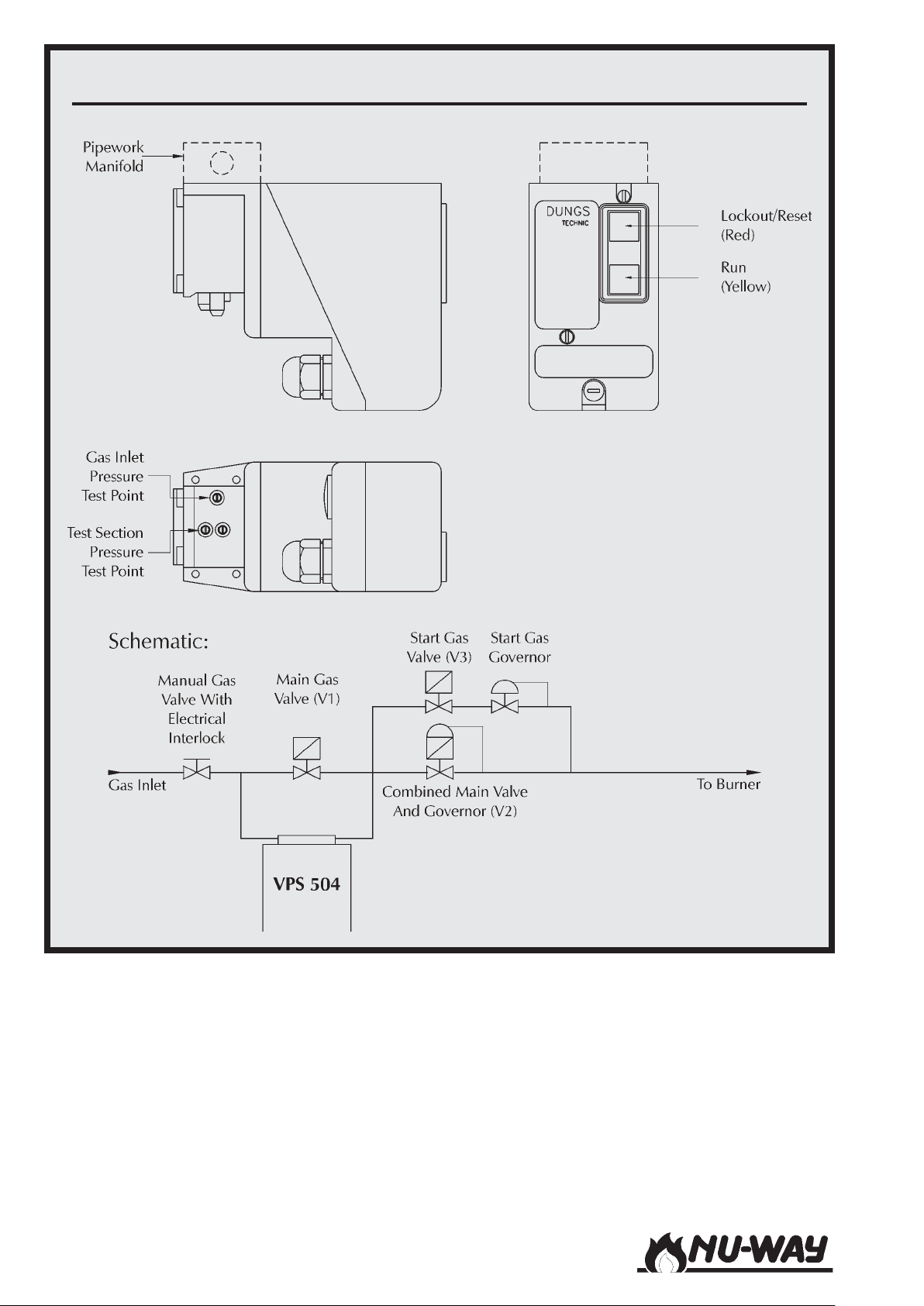
VALVE PROVING SYSTEM : VPS 504
(Optional Fitting)
The programmer starts functioning when the burner
controlling circuit is made. With valves V1, V2 and
V3 in the closed position, an internal pump increases
the gas pressure within the test section to 20 mbar
above the pressure at the inlet to the valve train.
During the test time an integral differential pressure
switch monitors the test section for leaks. When the
test pressure is reached the pump is switched off. If
the proving check has been successful (max. 30 seconds) the control circuit is released accompanied by
illumination of the yellow indicator light on the unit.
Models NDF35 to NDF150Page 24
If the proving check has been unsuccessful or if a pressure rise of 20 mbar has not been reached during the
test time (max. 26 seconds), the unit will switch to
the fault condition accompanied by illumination of
the red indicator light. This condition will remain until
the unit is manually reset or the control circuit is broken.
Page 25
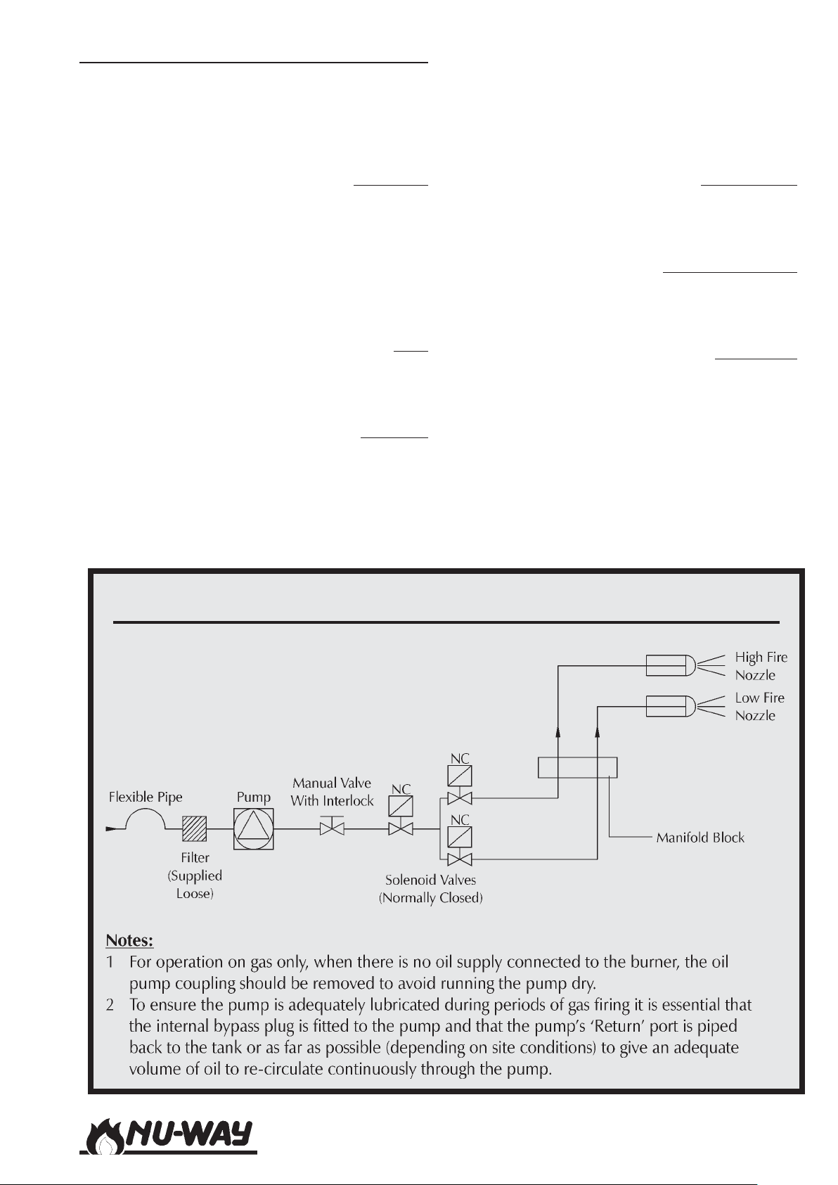
Oil Controls - Twin Pressure Jet Oil Burners
The oil control system used on NDFL burners with
twin pressure jet oil nozzles is shown on Page 25.
In addition to the oil pump it includes high and
low fire safety shut-off valves (normally closed type)
and a manually operated ball valve.
Oil Supply
Oil can be supplied from a two-pipe garvity system or from a two-pipe pumped ring main system. A two-pipe system is essential to enable oil
circulation through the oil pump during periods of
gas firing to ensure adequate lubrication. The oil
must be supplied and maintained at the temperatures and pressures given in the Table on Page 13.
Filter
The filter is usually supplied loose and must be
attached to the oil pump inlet prior to commissioning.
Oil Pump
The oil pump is mounted on the air inlet casing on
the right side of the burner. It is driven by the burner
motor through a flexible coupling.
When firing on gas for extended periods, it is recommended that this coupling is removed in order
to protect the pump from unnecessary wear.
Information on the pumps fitted to the NDF burner
range is given in the Table on Page 26.
The pumps are shown on Pages 27 -29.
Manual Valve
The manual valve is fitted with an electrical interlock to prove that the valve is in the closed position before the burner can be run on gas.
Oil Manifold Block
The oil manifold block is located below the burner
hinged extension. It connects the oil inner assembly to the external oil system.
Oil Nozzles
The two oil nozzles (high and low fire) are held in
a nozzle block located within the flame tube (refer
to the Appendix). The nozzles are pre-sized by Nuway in accordance with the heat inputs required
and the available operating pressure.
The oil nozzles are usually supplied in the instruction pack attached to the burner and must be fitted to the burner nozzle block prior to commissioning.
OIL CONTROL SYSTEM : TWIN PRESSURE JET OIL BURNERS
Models NDF35 to NDF150
Page 25
Page 26
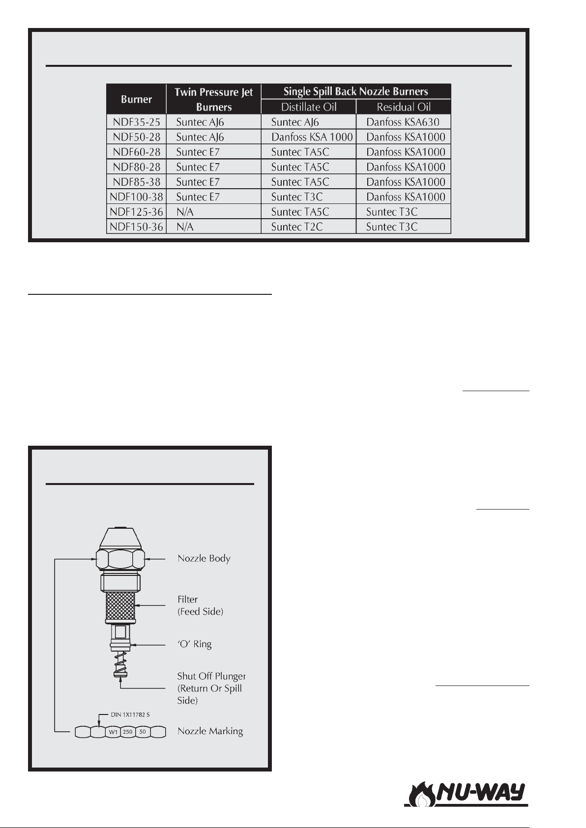
OIL PUMPS FITTED
Oil Controls - Single Spill Back Nozzle Oil
Burners.
The oil control system comprises the burner
mounted components and a separate pumping unit
for distillate fuels or pumping/heating unit for residual fuels.The burner mounted components are
similar for both light and residual oils. The separate oil pumping or pumping/heating set is connected to the burner utilising the braided high
pressure hoses supplied. The burner lance incorporates hydraulic tip shut off for the oil nozzle whilst the system controlling valves are closely
FLUIDICS W1 NOZZLE
mounted at the burner head.
Schematics of the oil controls are shown on Page
30 for residual fuels and Page 31 for distillate fuels.
Details of the pumping/heating set (for residual fuels), including the mounting arrangement are
shown on Page 32. The pumping set for distillate
fuels is shown on Page 33.
Manual Valve
On NDFL burners, a manual valve is fitted with an
electrical interlock, which proves that the valve is
in the closed position before the burner can be
run on gas.
This valve is not fitted to NDFR burners due to the
continual heating and recirculating requirements
of residual oils.
Oil Nozzle
NDFL Modulating / NDFR burners use a single oil
nozzle (Page 26) within the inner assembly (refer
to the Appendix).
This nozzle is factory-specified to deliver optimum
performance under the specified operating conditions. Any queries regarding the size of the nozzle
should be referred to Nu-way.
The nozzle is held in position by the inner assembly lance, through which oil flows from the manifold block to the nozzle and is recirculated through
the spill regulating valve.
Oil Manifold Block
The oil manifold block is located on the left side of
the hinged extension. It carries gauges which indicate pump pressure, hydraulic pressure and spill
pressure.
Models NDF35 to NDF150Page 26
Page 27
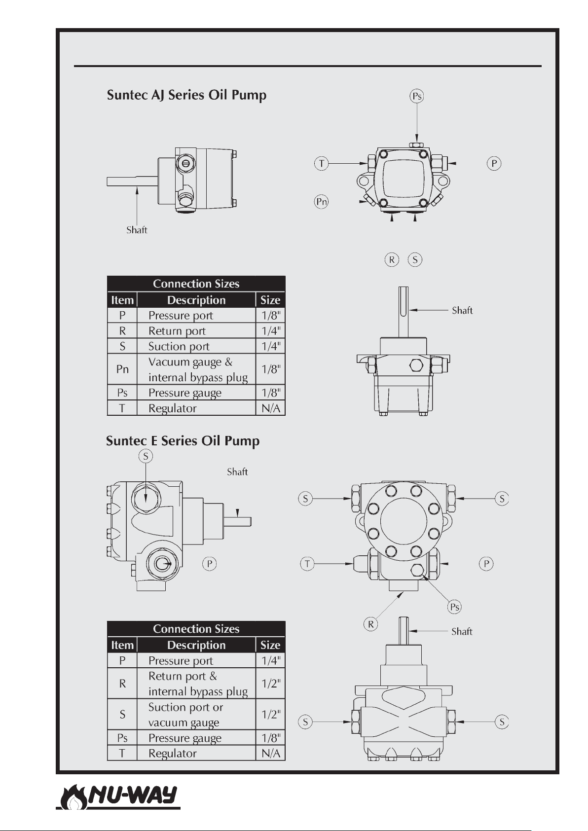
SUNTEC OIL PUMP IDENTIFICATION AND PORT SIZING
Models NDF35 to NDF150
Page 27
Page 28
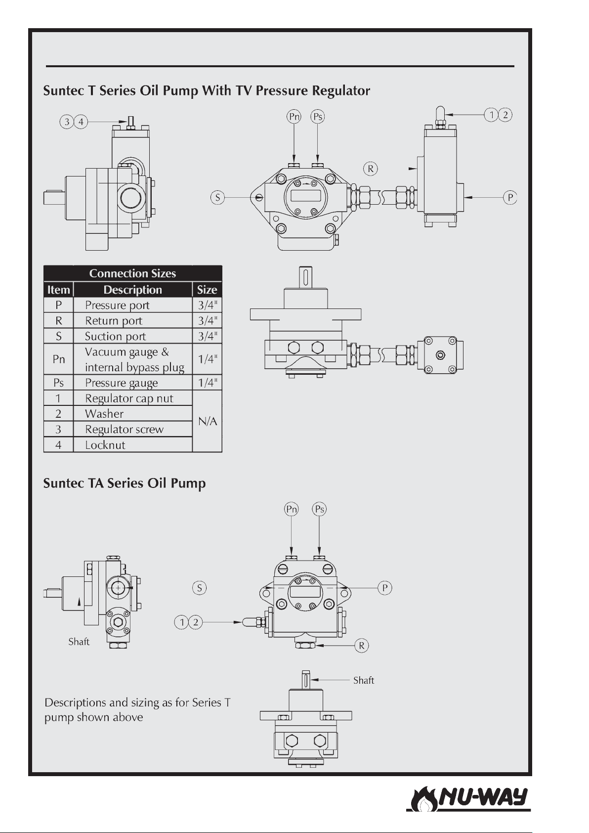
SUNTEC OIL PUMP IDENTIFICATION AND PORT SIZING
Models NDF35 to NDF150Page 28
Page 29
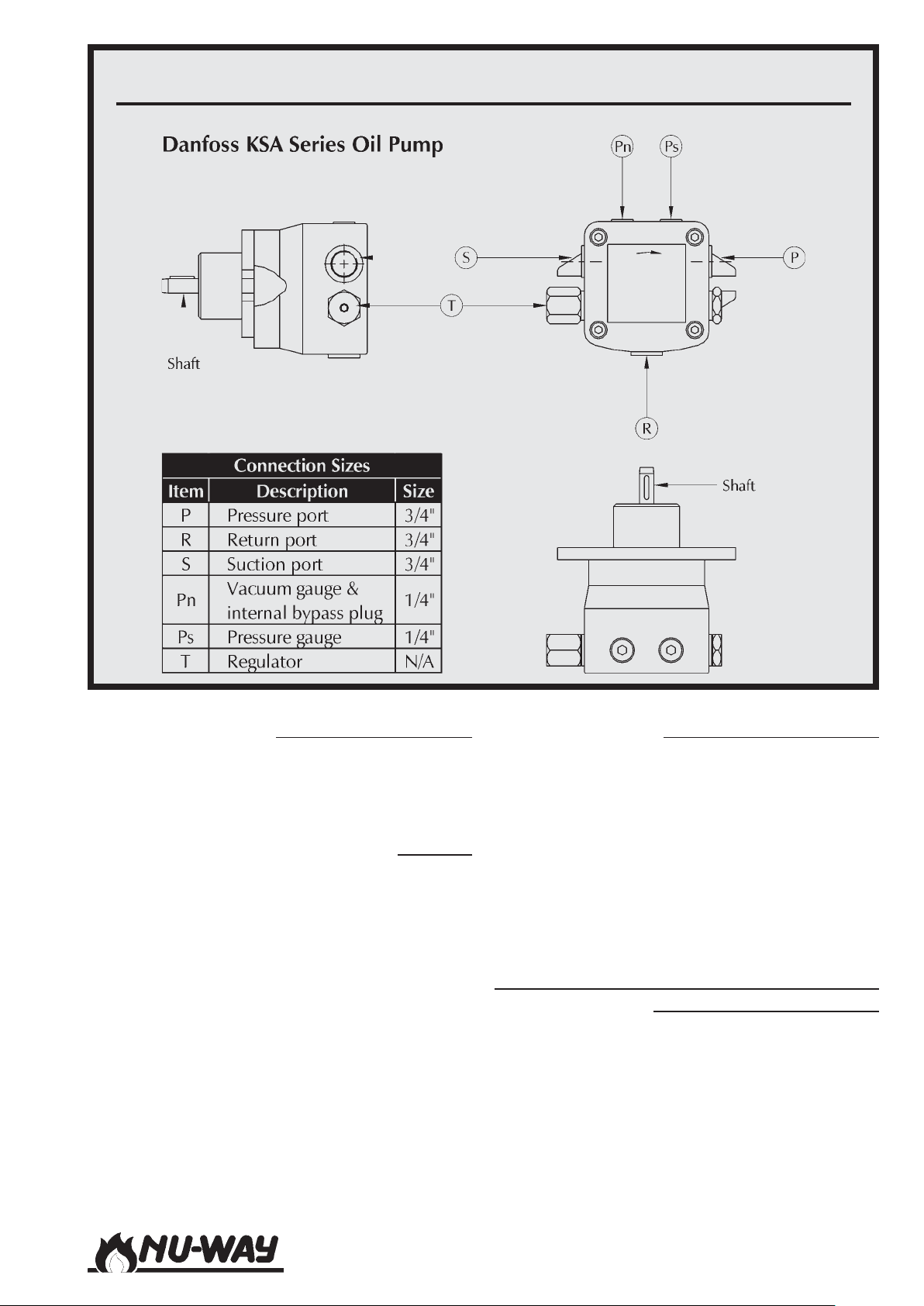
DANFOSS OIL PUMP IDENTIFICATION AND PORT SIZING
Oil Spill Regulating Valve
The oil spill regulating valve is actuated by the motor which actuates the air damper. It varies the spill
pressure in order to provide the required oil flow
rate at each operating condition.
Oil Pump
The oil pump is incorporated into a free-standing
packaged unit as shown schematically on Pages
32 and 33. This package includes the oil filters, an
air separation bottle and in the case of NDFR burners the oil preheater tank (including a thermometer to indicate outlet oil temperature) and the
return thermostat which ensures that the
recirculating oil temperature is maintained at an
appropriate level during shutdown periods.
Information on the pumps fitted to the NDF burner
range is given in the Table on Page 26.
The pumps are shown on Pages 27 -29.
Dummy Oil Inner Assembly
For NDFR burners firing ëGí class fuel, a dummy
oil inner assembly is available as an option. This
enables the oil lance to be removed during extended periods of gas firing, with the dummy assembly replacing it.
This will enable the oil pumping and heating unit
to continue to keep the oil system up to temperature without danger of oil being released into the
appliance whilst firing the burner on gas.
Control Panel
Twin Pressure Jet Oil Burners
On NDFL 2 stage burners the programming burner
controller, ignition transformer, contactors and
other items are located in an enclosure mounted
on the left side of the burner.
Models NDF35 to NDF150
Page 29
Page 30
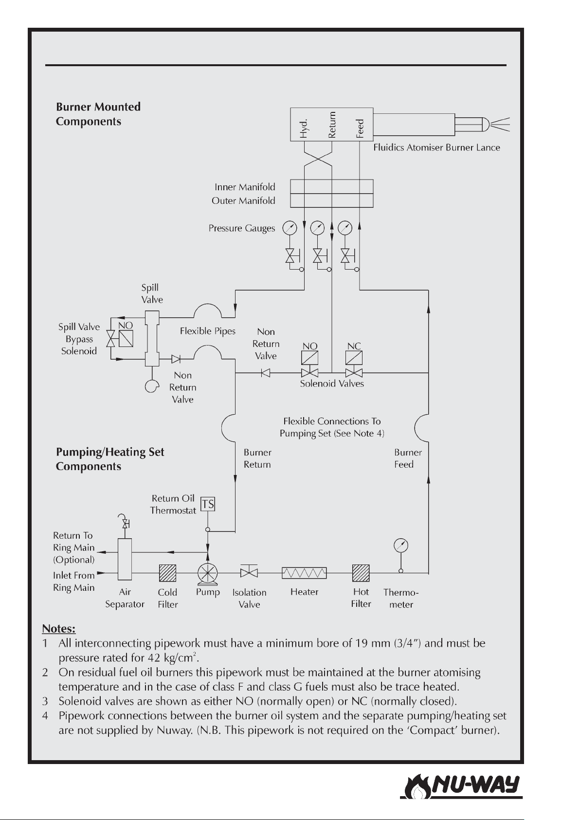
OIL CONTROLS : SINGLE SPILL BACK NOZZLE RESIDUAL OIL BURNERS
Models NDF35 to NDF150Page 30
Page 31
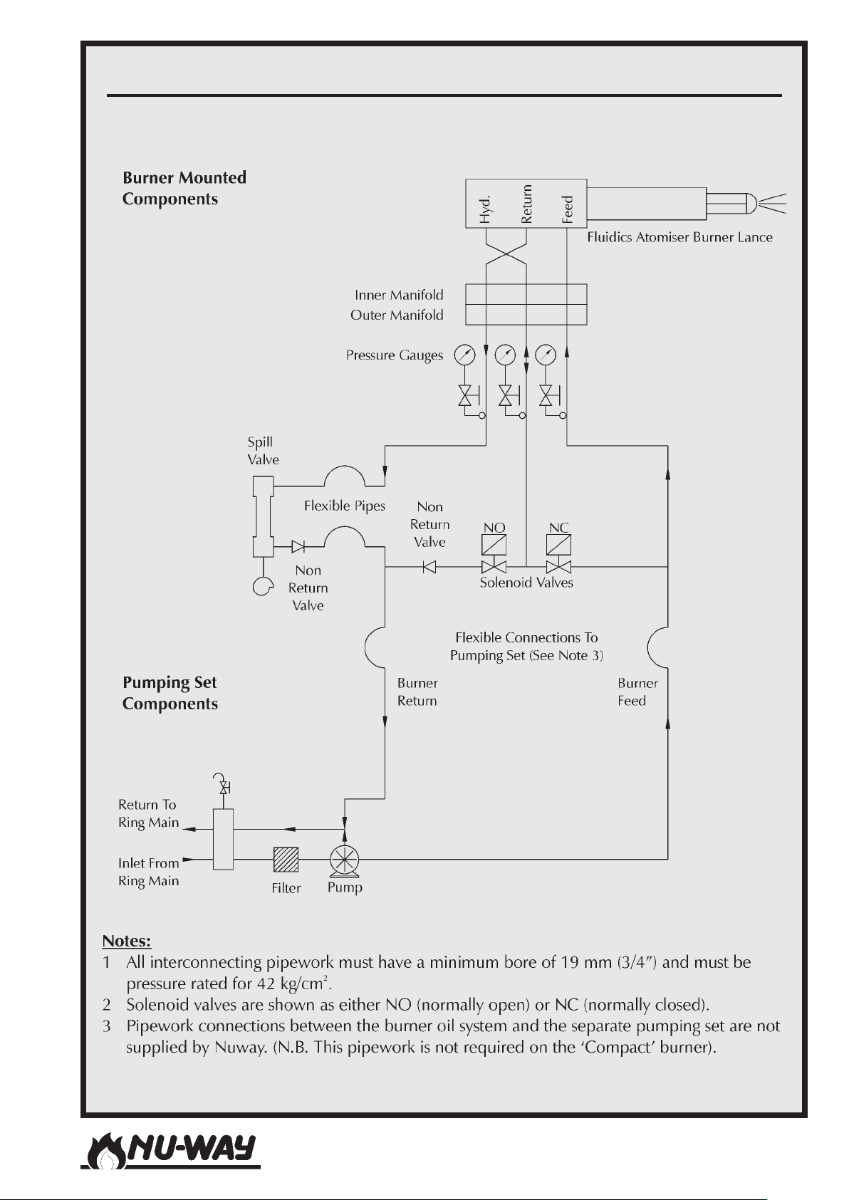
OIL CONTROLS : SINGLE SPILL BACK NOZZLE DISTILLATE OIL BURNERS
Models NDF35 to NDF150
Page 31
Page 32
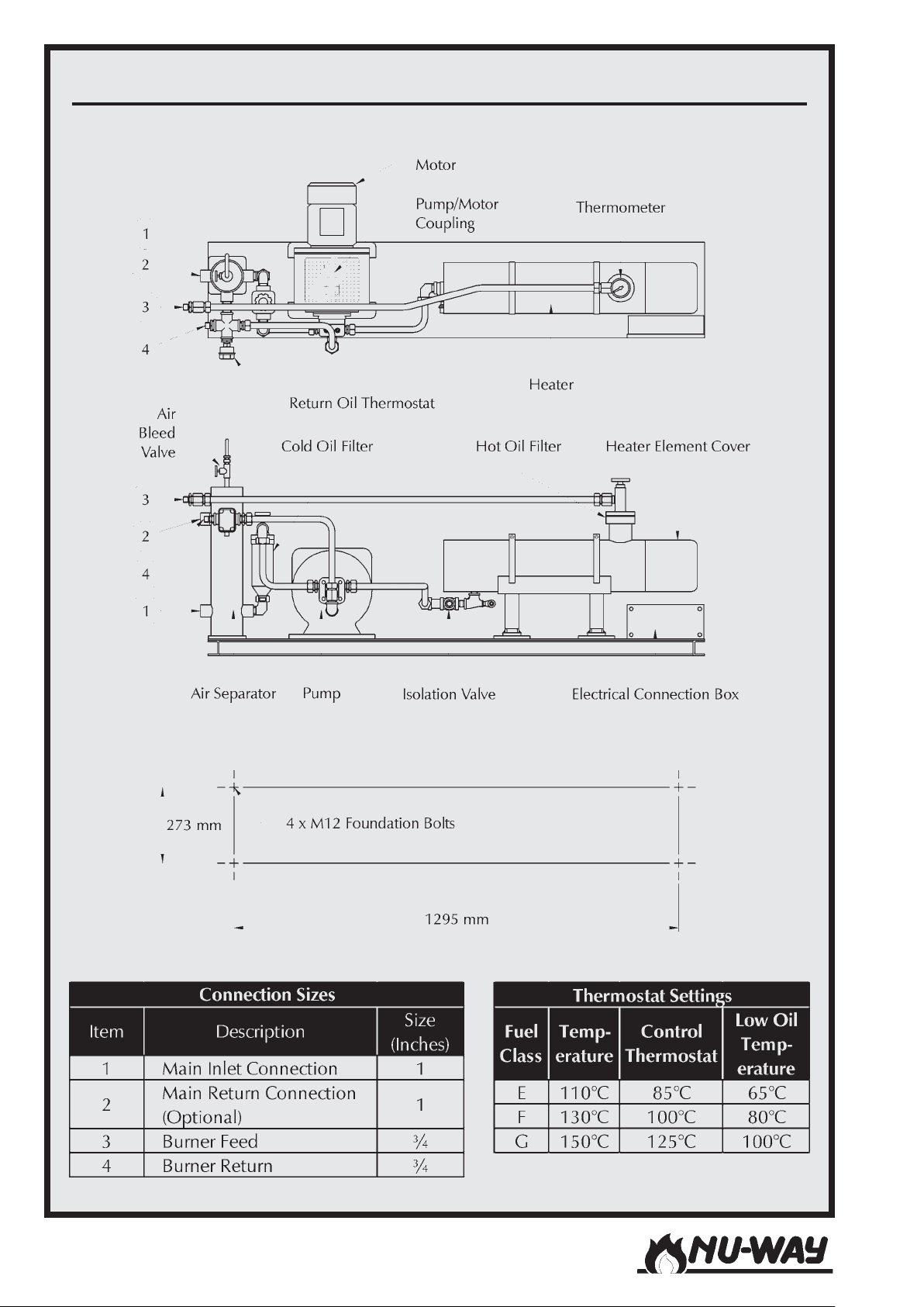
OIL PUMPING/HEATING SET FOR RESIDUAL FUELS
Models NDF35 to NDF150Page 32
Page 33
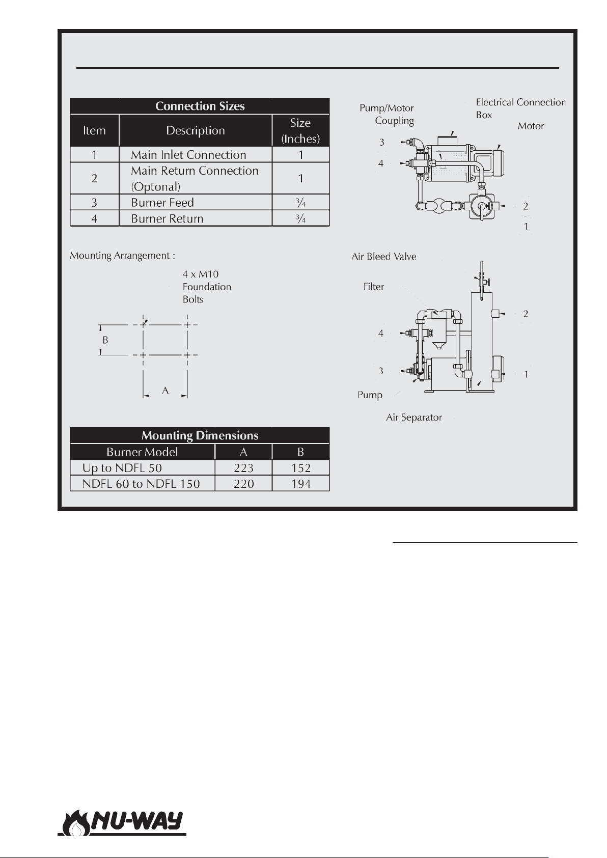
OIL PUMPING SET FOR DISTILLATE FUELS
The front panel of this enclosure carries the burner
On/Off switch and two neon indicator lights. The
amber light indicates "BURNER ON" and the red
light is illuminated when the burner stops as a result of "EXCESS TEMPERATURE / PRESSURE" in the
appliance.
The fuel selector switch and two additional neon
indicator lights are mounted on the side of the
enclosure. The amber light is illuminated when
"OIL" is the chosen fuel and the red light indicates
that "GAS" has been selected.
Models NDF35 to NDF150
Single Spill Back Nozzle Oil Burners
On NDF Modulating and Sliding High/Low burners, the enclosure mounted on the left side of the
burner serves mainly as a housing for electrical
connections, although it also contains the ignition
transformers and carries the burner On/Off switch,
the Hand/Auto switch and the Inching switch required by modulating burners
A separate free-standing panel contains the programming burner controller, contactors and other
items. This enclosure carries an amber light which
indicates "BURNER ON" and a red light which is
illuminated when the burner stops as a result of
"EXCESS TEMPERATURE / PRESSURE" in the appliance.
Page 33
Page 34
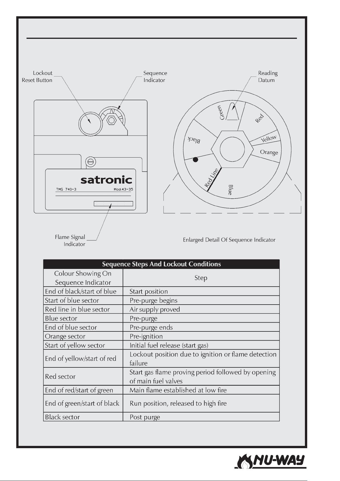
BURNER CONTROLLER : SATRONIC TMG 740
Models NDF35 to NDF150Page 34
Page 35
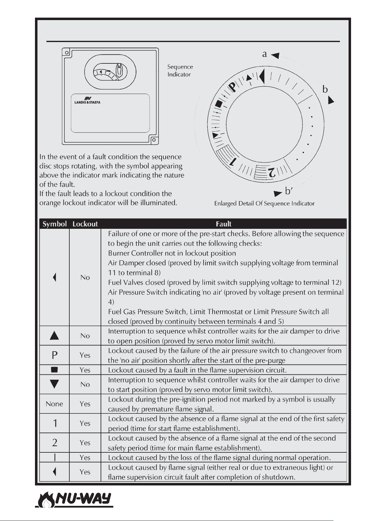
BURNER CONTROLLER : LANDIS & STAEFA LFL 1
Models NDF35 to NDF150
Page 35
Page 36
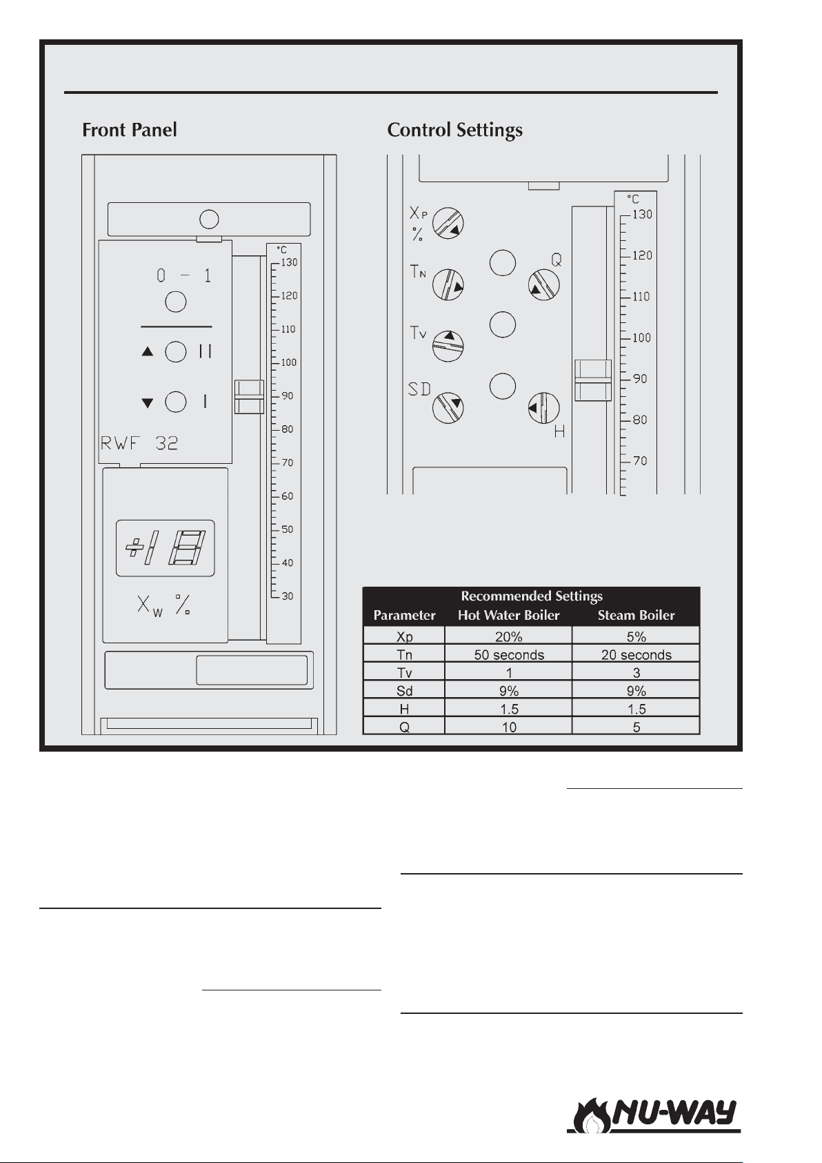
MODULATION CONTROLLER : LANDIS & STAEFA RWF 32
Also located on this enclosure are the fuel selector
switch and two additional neon indicator lights.
The amber light is illuminated when "OIL" is the
chosen fuel and the red light indicates that "GAS"
has been selected.
Burner Controller
The burner controller, together with the flame
monitor (see below), provide a safe light up and
shut down sequence for the burner.
Twin Pressure Jet Burners.
Two options are available, the Satronic TMG 740-
3 (shown on Page 34) or the Landis & Staefa LFL
1.333 (shown on Page 35)
Models NDF35 to NDF150Page 36
Single Spill Back Burners.
The Landis & Staefa LFL 1.333 (shown on Page
35) is fitted as standard.
Flame Monitor
In standard configuration, NDF burners are fitted
with a continuous flame supervision system which
uses an ultraviolet (UV) cell and amplifier (incorporated within the burner controller) to detect the
presence of the flame.
Modulating Controller
The Landis & Staefa RWF 32 (see Page 36) is fit-
ted as standard to all fully modulating burners.
Page 37
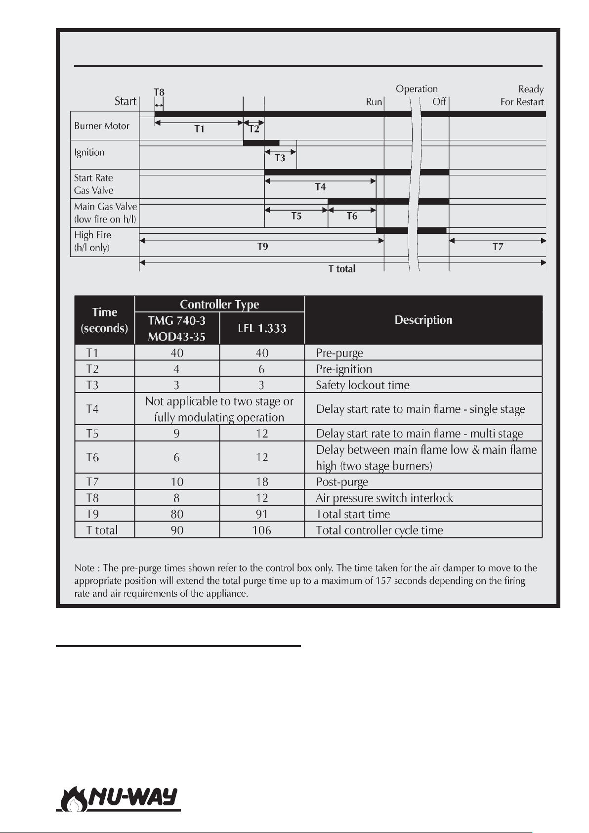
BURNER CONTROLLER SEQUENCE AND TIMING CHART
BURNER OPERATING SEQUENCE
The NDF burner operating sequence (refer to the
controller sequence diagram on Page 37 ) begins
with a pre-purge period on full air. When gas is
selected this fuel is then supplied to the burner at
start rate and ignition initiated. Start gas flame proving is followed by establishment of the main flame.
Models NDF35 to NDF150
When oil is selected, on completion of the prepurge period the appropriate oil valve or valves
open, ignition is initiated and the flame is established.
In both cases, the burner controller will then continue to its normal operating position and the operation of the burner will be controlled by the pressure and/or temperature requirements of the appliance.
Page 37
Page 38

MODULATING CONTROLS
Controller
The standard method of operation is based on the
Landis & Staefa RWF32 Universal Controller, which
has been designed for use in oil and gas fired installations, where it provides temperature or pressure control of modulating burners with continuously adjustable fuel throughput.
The control output of the RWF32 is a potential
free 3-position switch, which is used for the control of reversible motors. The control signals for
the open (Y1) and closed (Y2) are indicated on the
controller face by light emitting diodes.
Replaceable range insert circuit boards which are
used in conjunction with passive detectors of type
QAE22 (temperature) and QBE61 (pressure)
achieve configuration of the unit to a control value
and setting range.
When the boiler control calls for heat, the modulating servomotor will travel to the high flame position and interlock the control circuit. An air prepurge will take place at this position for a pre-determined period, at the end of which the burner
sequence controller will stop until the modulating
servomotor has travelled to the low flame position
and interlocked the control circuit again. The sequence controller will now recommence its operational cycle and the burner will light and remain at low flame until the high flame release signal is given by the sequence controller.
The modulating servomotor will now move to high
flame and remain at this position until the desired
boiler temperature/pressure is attained. From this
stage the modulating unit will commence to move
towards the low flame position, but, depending
on the temperature/pressure, will stop in any intermediate position between low and high flame.
Commissioning Controls
Two switches, Hand/Auto and Inching, are included in the burner panel. In Auto mode the
burner will respond to the demand of the boiler
via the RWF32 modulating controller. In ëHandí
mode, the RWF32 controller is disconnected from
the burner modulating servo. This servo can now
be 'inched' towards high or low flame by operating the 3 position bias inching switch, thus allowing combustion settings to be made at these points.
Whilst in ëHandí mode, care must be exercised
when the burner is in a high firing range so that
the boiler demand is not exceeded. It is imperative that the burner control circuit operating and
limiting instruments are fitted and functioning correctly.
Some panels may be fitted with a third switch marked
'Low Flame Hold'. This switch, when operated, has
the same effect as starting the burner in the 'Hand'
mode. That is, the burner will run through its starting
sequence, establishing flame at the low flame rate
and remaining at this state until manually commanded
otherwise. If the Low Flame Hold switch is activated
and the Hand/Auto switch is set in the Auto position,
releasing of the Low Flame Hold switch will result in
the Modulating Servo driving towards the high flame
position as determined by the RWF32 temperature
controller.
Temperature Detector
The immersion temperature detector type QAE22
is used in all hot water boiler applications. The
detector has a plastic casing to IP42 with a snap
on cover and an immersion stem. The connection
terminals can be accessed after removal of the
cover. Cable entry is made via a cable entry gland
Pg11. In all applications an immersion pocket with
a flat seal is supplied.
The detector should be installed in an elbow such
that the pocket points against the direction of flow.
With all detector versions, the immersion length
must be a minimum of 60mm.
Pressure Detector
The pressure detector type QBE61 is used in all
steam boiler applications. The detector has a plastic casing to IP42. It is necessary to mount the water trap pipe supplied.
General
The detector must not be covered by lagging.
Mounting instructions are printed on the packing.
The permissible lengths of the measuring cable be-
tween detector and controller are given in the following table:
Core
0.6 mm Diam. 5.5 mm 20 m
1.0 mm
1.5 mm
2
2
Outside
Diameter
6.6 mm 80 m
7.2 mm 120 m
Line
Length
Models NDF35 to NDF150Page 38
Page 39

COMMISSIONING : GENERAL
Safety
It is essential that commissioning shall be undertaken only by suitably qualified and experienced personnel. In the case of NDF burners,
commissioning engineers should be experienced
in commissioning forced draught oil and gas
burners.
In the UK, it is a legal requirement that anyone
working on gas installations, as defined in the
"Gas Safety (Installation And Use) Regulations
1994", is CORGI registered.
Nu-way can accept no responsibility for consequential loss, damage or injury which results
from a failure to follow the commissioning instructions provided or from commissioning procedures being undertaken by unqualified personnel.
In An Emergency
NDF burners are designed and constructed to
meet all essential requirements of the Gas Appliance Directive 90/396/EEC.
When used in accordance with the instructions
provided, NDF burners are unlikely to produce
a hazardous condition. If, however, such a condition should arise in connection with the burner,
the appliance or any instrument, machine or
service in the vicinity of the burner, the FUEL
AND ELECTRICITY SUPPLIES SHALL BE ISOLATED IMMEDIATELY and they shall remain isolated until the fault has been identified and rectified.
Inspection
Before commissioning is begun it is important to:
1 Check that the electrical wiring is complete and
complies with all applicable Codes and Standards.
2 Ensure that the fuses are fitted and of the cor-
rect ratings.
3 Check electrical earthing.
4 Verify that the gas and oil supply pipework is
correctly sized and that it has been checked
for leakage.
5 Ensure that the manual gas isolation valve at
the inlet to the gas train and the ball valve on
the oil line are operable, fully closed and leak
tight.
6 Make all personnel involved in the commis-
sioning aware of the location of the emergency
gas, oil and electricity isolation points.
7 Check that fittings such as purge and test points
are available.
8 Establish that the appliance is in an appropri-
ate and safe condition to be fired; for example, that there is water in the boiler.
9 Set the appliance controls to call for heat. Check
the appliance's ventilation and flueing arrangements.
10 Ensure that any warning notices appropriate to
the commissioning procedure are in position.
11 Ensure that all necessary tools and test equip-
ment are available and ready for use.
Essential items include a manometer or other
approved pressure measuring instrument,
means (which may be permanently installed
or provided specifically for commissioning) of
measuring the flow rates of oil and gas, equipment for checking the smoke number of the
flue products and a means of analysing the flue
products for carbon dioxide (CO2), oxygen (O2)
and carbon monoxide (CO).
12 Check that all relevant documentation is avail-
able, including, where appropriate:
- The agreed plant performance specification.
- Plant drawings and pipework layouts.
- Electrical logic and wiring diagrams.
- Certificates confirming satisfactory completion of procedures such as soundness
testing, purging and electrical safety tests.
- Commissioning, operating, emergency
shutdown and maintenance instructions
for the plant.
13 Establish that the operation of plant other than
that being commissioned will not have an adverse effect on the operation of the plant to be
commissioned and similarly, that the operation
of the plant to be commissioned will not have
an adverse effect on other plant.
14 Confirm that the operation of adjacent plant
and machinery will not constitute a hazard to
the personnel involved in commissioning.
Models NDF35 to NDF150
Page 39
Page 40

Initial Settings
To prepare the burner for commissioning on oil
and gas:
1 Remove the cover from the air damper mo-
tor and check the cam positions referring to
the appropriate diagram shown on Page 18
or 19. Adjust if necessary.
2 Remove the small plate on top of the gover-
nor section of the air/gas ratio controller.
Referring to the diagram on Page 21, set the
air/gas ratio on scale (1) to 0.8 by adjusting
screw (1), anti-clockwise to increase, clockwise to decrease. Set the ratio on the remaining scale to half a division on the positive
side of '0' by adjusting screw (2) in the same
way; anti-clockwise to increase, clockwise to
decrease.
3 Remove the cap from the start gas governor
and set the adjusting screw approximately
half way between the maximum and minimum settings, turning the screw clockwise
to increase the setting and anti-clockwise to
decrease it. Replace the cap. Never adjust
the governor to its maximum setting.
4 Check and if necessary re-set the ignition
electrode gaps to 2.5 to 3 mm. Access to the
burner head is explained on Page 52.
5 Ensure that oil of the correct class is avail-
able at the required temperature (on NDFR
systems: refer to the table on Page 13) and
pressure.
IT IS RECOMMENDED THAT THE BURNER
SHOULD BE COMMISSIONED FOR OIL FIRING
IN THE FIRST INSTANCE. SHOULD OIL NOT BE
AVAILABLE TO THE BURNER THEN GAS COMMISSIONING CAN PROCEED ONLY IF THE
PUMP DRIVE COUPLING IS REMOVED FROM
THOSE BURNERS WHERE THE OIL PUMP IS
DRIVEN BY THE BURNER FAN MOTOR. IT MUST
BE NOTED IN ALL CASES THAT WHEN OIL IS
AVAILABLE TO THE BURNER THE UNIT MUST
BE RE-COMMISSIONED ON BOTH FUELS. NOTICE SHOULD BE MADE OF THIS FACT, BOTH
AT THE BURNER AND WITHIN THE BURNER
HANDBOOK AND APPLIANCE LOGBOOK.
COMMISSIONING : OIL
Burner Dry Run - Twin Pressure Jet Burners
(NDFL35-25 to 100-38 Two Stage (High/
Low))
The following procedure should be followed. It is
important that a complete and flawless dry run be
completed before fuel is supplied to the system.
1 Check that the gas, oil and electrical power
supplies to the burner are turned off. Turn
the fuel selector switch on the control panel
to the oil position.
2 Check that the manual gas isolation valve at
the inlet to the gas train is closed and that
the ball valve between the oil pump and fuel
valves in the burner oil line is open.
3 Ensure that oil is available at the oil pump
on the burner at the required pressure and
class.
4 Prime the oil pump by opening the bleed
port until air-free oil flows from it. The pump
should not be rotated automatically until it
has been primed as this may lead to premature wear or pump seizure.
5 Open the panel door and set the burner to
low flame hold.
6 Set the air pressure switch to minimum.
7 Establish the electricity supply to the burner
and momentarily switch on the burner. Ob-
serve the rotation of the combustion air fan
motor, which should be anti-clockwise
viewed from the motor cowl end. If the di-
rection of rotation of the fan motor is incor-
rect, refer to the Section of this handbook
on Fault Finding.
8 If the fan rotation is correct switch on the
burner.
9 The burner motor will begin to run:
(a) Immediately if the system was switched
off during normal operation.
(b) On resetting the sequence control box
using the Off/On/Reset switch.
If at this stage the burner goes to lockout,
refer to the Section on Fault Finding.
10 The burner will proceed through its pre-purge
and ignition sequences. Check that an igni-
tion spark is present. If there is no spark and
the burner goes to lockout, the air pressure
switch may be at fault - refer to the Section
on Fault Finding.
Models NDF35 to NDF150Page 40
Page 41

11 Allow the burner to light momentarily. Switch
off the burner and the electrical supply to
the burner.
12 The burners safety systems have now been
proven on oil firing and commissioning can
proceed to the next stage.
Burner Live Run - Twin Pressure Jet Burners
(NDFL35-25 to 100-38 Two Stage (High/
Low))
The instructions in this section are presented as a
continuous sequence. No separate set of actions (for
example, checking the flame signal) should be followed in isolation without paying particular attention to any safety precautions such as isolating the
electrical supply to the burner which should precede
such actions. At all stages, the operation of the burner
should be checked against the programming controller sequence diagram on Page 37.
Setting Oil Flow Rates and Air/Fuel Ratios
From this point the oil commissioning process is concerned with setting the high and low fire oil flow rates
to appropriate values and ensuring that the combustion quality of the system is within acceptable limits.
During this process:
AFTER EACH ADJUSTMENT check the flue gas
analysis and oil flow rate.
ALWAYS use approved and calibrated test equipment.
NEVER rely on visual observation of the flame as
the only guide to combustion quality.
1 Open the manual shut-off valve in the burner
oil line.
2 Switch the burner on. Following the pre-purge
period the burner will initiate the ignition spark
and open the low fire oil valve.
3 The flame will be established and the UV cell
will begin monitoring. The burner will operate
continuously at low fire.
4 Check the oil pump pressure at the pump. Ini-
tially, set the pressure to 20.7 bar (300 psi). Observe the flame through the inspection window
at the rear of the burner casing to ensure the
flame is established around the outer edge of
the diffuser plate. A continuous halo should be
visible.
5 The burner is fitted with a five cam air damper
servo (refer to the diagram on Page 18). Adjust
the low fire air control cam (cam 2) if necessary so that the appearance of the flame is satisfactory.
6 Sample the flue products and check the smoke
number. Adjust the low flame air cam until a
clean, efficient flame is achieved.
7 Switch off the burner. The flame should go out
immediately with the oil pressure gauge falling
to just above zero. Switch off the electrical supply to the burner.
8 Open the control panel door and switch the
burner from low flame hold to normal run position. Re-secure the panel door.
9 Establish the electrical supply and switch on
the burner. Allow the burner to proceed
through its operating sequence until it is operating on high fire.
10 Observe that the flame is clear and steady with
a continuous halo visible around the diffusers
outer edge.
11 Sample the flue products and check the smoke
number. Adjust the high flame air cam (cam 3)
until a clean and efficient flame is achieved.
12 Check the oil flow rate. The appropriate low
fire rate is 55% (1.8:1 turndown) of the high
fire rate.
13 Re-adjust the pump pressure if necessary to
correct the oil flow rate at high flame.
14 The servomotor is fitted with 2 cams (refer to
the servomotor details on Page 18) which allow independent switching of the high flame
oil valve when moving from low to high flame
and vice-versa. These switches are factory set
but may be adjusted to improve the change
over characteristics if necessary.
15 Analyse the flue products on both high and low
fire.
16 Repeat the process of checking oil flow rate,
smoke number and flue product analysis until
satisfactory results are obtained at both high
and low fire.
17 Switch off the burner and the electrical power
supply to the burner.
Burner Dry Run - Single Spill Back Burners
(NDFL Modulating / NDFR - All Models)
The following procedure should be followed. It is
important that a complete and flawless dry run be
completed before fuel is supplied to the system.
1 Check that the gas, oil and electrical supplies
to the burner are turned off. Turn the fuel
selector switch on the control panel to the
oil position.
Models NDF35 to NDF150
Page 41
Page 42

2 Check that the manual gas isolation valve at
the inlet to the gas train is closed. Do not
close the ball valve at the outlet of the oil
pumping set.
3 Ensure that oil is available at the oil pump
on the burner at the required pressure and
class.
4 NDFL Burners: Prime the oil pump by open-
ing the bleed port until air-free oil flows from
it. The pump should not be rotated automatically until it has been primed as this may lead
to premature wear or pump failure.
5 NDFR Burners:
(a) Fill the oil pre-heater tank by removing
the hot oil filter retaining flange in the
outlet pocket on top of the tank. Fill to
the neck of the outlet with clean fuel
oil only.
(b) Check the pre-heater thermostat set-
tings, the recommended settings are
shown on Page 32.
6 Switch on the electricity supply to the burner
and check that the pump rotation is correct
to the direction arrows shown on the pump
face.
7 Open the manual isolation valve at the out-
let of the pumping set.
8 Open the control panel door and set the
burner for low flame hold.
9 Set the air pressure switch to minimum.
10 Remove the access lid on the modulating cam
box unit.
11 Switch on the burner at the control panel.
On NDFR burners a delay may be experi-
enced whilst the system attains temperature.
The modulating unit camshaft should now
rotate to the high flame setting, and the com-
bustion fan motor will start the air pre-purge
phase.
12 Allow the fan motor to run up to speed and
switch off the burner. Observe the rotation
of the combustion air fan motor, which
should be anti-clockwise viewed from the
motor cowl end. If the direction of rotation
of the fan motor is incorrect, refer to the Sec-
tion of this handbook on Fault Finding.
13 If the fan rotation is correct switch on the
burner.
14 The burner will proceed through its pre-purge
and ignition sequences. Check that an ignition spark is present. If there is no spark and
the burner goes to lockout, the air pressure
switch may be at fault - refer to the Section
on Fault Finding.
15 During this run note the spill and line oil pres-
sures at the point of ignition. Reset the sequence control and repeat the run if necessary to check these functions. If necessary,
adjust the line pressure at the burner pump
to 27.8 bar (400 psi) and the spill pressures
to the correct figures stamped on the burner
data plate.
16 Allow the burner to light momentarily. Switch
off the burner and the electricity supply to
the burner.
17 The burnerís safety systems have now been
proven on oil firing and commissioning can
proceed to the next stage.
Burner Live Run - Single Spill Back Burners
(NDFL Modulating / NDFR - All Models)
The instructions in this section are presented as a
continuous sequence. No separate set of actions
(for example, checking the flame signal) should be
followed in isolation without paying particular attention to any safety precautions such as isolating
the electrical supply to the burner which should
precede such actions. At all stages, the operation
of the burner should be checked against the programming controller sequence diagram on Page
37.
Setting Oil Flow Rates and Air/Fuel Ratios
From this point the oil commissioning process is
concerned with setting the high and low fire oil
flow rates to appropriate values and ensuring that
the combustion quality of the system is within acceptable limits. During this process:
AFTER EACH ADJUSTMENT check the flue gas
analysis and oil flow rate.
ALWAYS use approved and calibrated test equipment.
NEVER rely on visual observation of the flame
as the only guide to combustion quality.
Models NDF35 to NDF150Page 42
Page 43
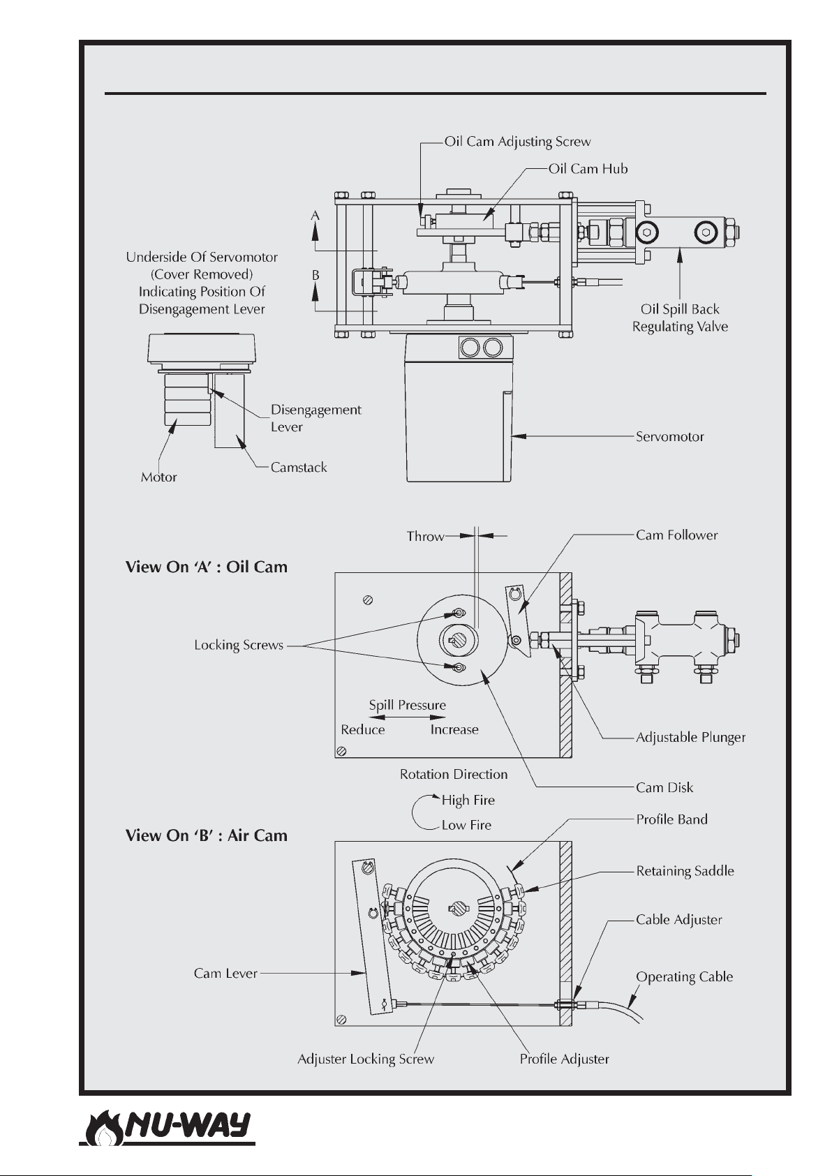
MODULATING CAM BOX
Models NDF35 to NDF150
Page 43
Page 44

New NDF Modulating burners are generally supplied against the firing specification of the appliance. In this case the system and spill pressures
may be pre-set and require checking and minor
adjustments only. The following section describes
how to set up the modulating cam box unit from
the beginning. The modulating cam box is shown
on Page 43.
The modulating cam layshaft can be rotated by
hand by using the gearbox disengagement lever in
the drive servomotor.
1 Ensure that the modulating cam arrangement
is in the low flame position. Adjust the oil
cam (refer to Page 43) so that it gives approximately 1.5mm throw (3mm stroke) and
lock in position.
2 Check to ensure that the spill valve push rod
bears lightly against the oil cam (refer to Page
43).
3 Turning to the air cam, rotate the thumb-
screws in or out so that they give a reasonable amount of adjustment in each direction.
Adjust the flexible cable (at either end if necessary) until the air inlet damper is fully closed
(i.e. until all the slack is taken up on the cable).
4 Adjust the thumbscrews to give a small open-
ing of the air damper at low flame.
5 Reset the sequence control and allow the
burner to start. Immediately the burner starts,
switch the Hand/Auto selector switch to the
'Hand' position and hold low flame until the
appliance is ready to accept high flame. During this period, check and adjust the low
flame oil throughput.
6 Observe the flame through the inspection
window at the rear of the burner casing to
ensure the flame is established around the
outer edge of the diffuser plate. A continuous halo should be visible. If the flame is dirty,
adjust the air cam thumbscrews until the
flame becomes clean.
7 After a suitable delay, inch the camshaft to
the high flame position (i.e. through 180∞)
by means of the inching switch on the control panel. Adjust the air cam profile by means
of the thumbscrews until the air damper is
now fully open. At this stage it will be found
that all of the thumbscrews between low and
high position will require adjusting so as to
avoid over stressing the cam profile band.
Once this has been done, there should be a
fairly smooth profile between low and high
flame positions.
8 Ensure that the flame is visually clean
throughout the modulation range at all times.
9 Check the oil consumption. If this is not cor-
rect for the full burner rating, the oil cam
must be adjusted as follows: -
(a) Inch the burner to low flame and note
the spill pressure.
(b) To increase the minimum rate, adjust
as shown on Page 43.
(c) Adjust the cam to give more eccentric-
ity for more oil at high flame, and viceversa.
(d) Return to the minimum setting and
compensate for any changes.
(e) Inch the burner to high flame and again
check the oil flow.
Continue to repeat (a) to (d) until the high
flame oil rate is correct.
10 When a satisfactory flame is achieved, again
check the line and spill pressures. Check the
pre-heater temperature (if fitted) and adjust
if necessary.
11 Inch the camshaft back to the low flame po-
sition. The oil consumption rate should now
be between 40 and 50% of the rated maximum.
12 Sample the flue products and check the
smoke number. Adjust the combustion air
volume as necessary.
13 Check the burner performance throughout
the range adjusting the air cam profile as
necessary to give a clean and efficient flame.
When a satisfactory setting has been
achieved, lock the air cam thumbscrews with
the grubscrews fitted in the side face of the
cam body. Refit the modulating cam unit access cover.
14 Switch off the burner and the electricity sup-
ply to the burner.
Models NDF35 to NDF150Page 44
Page 45

COMMISSIONING : GAS
Burner Dry Run - NDFL/R All Models
The following procedure should be followed. It is
important that a complete and flawless dry run be
completed before fuel is supplied to the system.
IT IS RECOMMENDED THAT THE BURNER
SHOULD BE COMMISSIONED FOR OIL FIRING
IN THE FIRST INSTANCE. SHOULD OIL NOT BE
AVAILABLE TO THE BURNER THEN GAS COMMISSIONING CAN PROCEED ONLY IF THE
PUMP DRIVE COUPLING IS REMOVED FROM
THOSE BURNERS WHERE THE OIL PUMP IS
DRIVEN BY THE BURNER FAN MOTOR. IT MUST
BE NOTED IN ALL CASES THAT WHEN OIL IS
AVAILABLE TO THE BURNER THE UNIT MUST
BE RE-COMMISSIONED ON BOTH FUELS. NOTICE SHOULD BE MADE OF THIS FACT, BOTH
AT THE BURNER AND WITHIN THE BURNER
HANDBOOK AND APPLIANCE LOGBOOK.
Important Note Regarding Combustion Air Settings: -
IF THE BURNER HAS ALREADY BEEN COMMISSIONED ON OIL, THE COMBUSTION AIR SETTING MUST NOT BE RE-ADJUSTED. THE GAS
RATE MUST BE MATCHED TO THE EXISTING
SETTINGS.
NDFR firing ëGí fuel
1 Check that the gas, oil and electrical power
supplies to the burner are turned off. Turn
the fuel selector switch on the control panel
to the gas position.
2 Check that the manual gas isolation valve at
the inlet to the gas train and the ball valve in
the oil line (NDFL) are closed.
3 On NDFR burners firing class 'G' fuel, if the
dummy inner assembly is to be used (see Page
29), open the hinged extension and remove
the oil lance from the gas inner assembly. The
lance and nozzle should be flushed through
with clean class 'D' oil immediately to prevent blockage by the cooling fuel oil.
Fit the three port dummy inner assembly
manifold supplied as an option. This will enable the oil pumping and heating unit to continue to keep the oil system up to temperature without danger of oil being released into
the appliance whilst firing the burner on gas.
Fit the inner assembly plug to the back of the
gas inner assembly. This maintains the cross
sectional area of the annular air passage
within the primary air tube, as if the oil lance
is fitted.
4 Check that the gas pipework between the
plant isolation valve and the safety shut-off
valves has been tested for soundness and
purged in accordance with an appropriate
Procedure, for example IGE/UP/1 ëSoundness
testing and purging on industrial and commercial premisesí.
5 Open the control panel cover and set the
burner for low flame hold. (On modulating
burners not fitted with a low flame hold
switch, set the Hand/Auto switch to the
ëHandí position).
6 If a gas booster is fitted, ensure that it is turned
on.
7 Remove the cover from the low gas pressure
switch and fit a temporary link between ter-
minals 2 and 3. Replace the cover.
8 Set the air pressure switch to minimum.
9 Establish the electrical supply to the burner
and momentarily switch on the burner. Ob-
serve the rotation of the combustion air fan
motor, which should be anti-clockwise
viewed from the motor end. If the direction
of rotation of the fan motor is incorrect refer
to the Section of this handbook on Fault Find-
ing.
10 If the fan rotation is correct switch on the
burner.
11 The burner motor will begin to run:
(a) Immediately if the system was switched
off during normal operation.
(b) On pressing the reset button on the
control box.
If at this stage the burner goes to lockout,
refer to the Section on Fault Finding.
12 The burner will proceed through its ignition
sequence. Check that an ignition spark is
present. If there is no spark and the burner
goes to lockout the air pressure switch may
require adjustment - refer to the Section on
Fault Finding.
13 The ignition spark will cease and the system
will go to lockout. Switch off the burner and
the electrical power supply to the burner.
Models NDF35 to NDF150
Page 45
Page 46

14 Switch off the gas booster (if fitted). Remove
the temporary link fitted to the low gas pressure switch and replace the cover.
15 The burner's safety systems have now been
proven and commissioning can proceed to
the next stage.
Burner Live Run - NDFL/R All Models
General
The instructions in this section are presented as a
continuous sequence. No separate set of actions
(for example, checking the flame signal) should be
followed in isolation without paying particular attention to any safety precautions such as isolating
the electrical supply to the burner which should
precede such actions. At all stages, the operation
of the burner should be checked against the programming controller sequence diagram on Page
37.
Before proceeding, check again that:
1 The electrical wiring is complete and com-
plies with all relevant Codes and Standards.
2 All fuses are fitted and are of the correct rat-
ings.
3 The gas and oil supply pipework is correctly
installed and has been leak tested. If, at any
time during commissioning, there is a SMELL
OF GAS the gas and electricity supplies must
be isolated and the leak sealed before proceeding.
4 The appliance is in an appropriate and safe
condition to be fired.
5 The appliance controls are set to call for heat.
Selecting Gas
1 Ensure that the ball valve in the oil line is
closed.
2 Turn the fuel selector switch on the control
panel to the gas position.
Gas Supply Pressure
The supply pressure at the inlet to the burner shall
not be less than that required for the maximum
required continuous output from the burner, and
not more than 100 mbar (up to NDF100-38) or
200 mbar (NDF100-41 and upwards). Refer to the
gas inlet pressure graphs (running pressures) contained in the appendix of this handbook. Before
proceeding with commissioning:
1 Fit a manometer or other approved pressure
measuring instrument to the pressure test
point on the upstream side of the first safety
shut-off valve.
2 Open the manual gas isolation valve at the
inlet to the gas train.
3 Check that the gas pressure is adequate.
Establishing the Start Gas Flame
1 Remove the control panel cover and remove
the pilot check link. Replace the cover.
2 Establish the electrical supply to the burner
and switch on the burner.
3 The burner controller will run through its se-
quence, initiating the ignition spark and
opening the start gas safety shut-off valve.
4 The start gas flame will be established and
the UV cell will begin monitoring. The burner
will operate continuously at start gas rate. If
the burner goes to lockout, increase the start
gas rate slightly at the governor and reset the
burner.
5 Confirm the leak tightness of the pipework
downstream of the start gas safety shut-off
valve using a proprietary detection fluid.
6 Switch off the burner. Switch on the burner
and allow the ignition sequence to be repeated, confirming that the start gas flame is
reliable.
7 Switch off the burner and the electrical power
supply to the burner. Remove the control
panel cover and replace the pilot check link.
Replace the cover.
Setting Main Flame Rates and Air/Gas Ratios
From this point the gas commissioning process is
concerned with setting the main and start gas flow
rates to appropriate values and ensuring that the
combustion quality of the system is within acceptable limits. During this process:
AFTER EACH ADJUSTMENT check the flue gas
analysis and gas flow rate.
ALWAYS use approved and calibrated test equipment.
NEVER rely on visual observation of the flame
as the only guide to combustion quality.
Models NDF35 to NDF150Page 46
Page 47

1 Fit a manometer or other approved pressure
measuring instrument to the gas pressure test
point nearest to the burner head. The relationship between the pressure at this point
and burner heat input is shown in the graphs
in the Appendix. This information is provided
only as a guide and it should not be used in
conjunction with pressure measurements as
a substitute for accurate measurement of gas
flow rate using, for example, a gas meter.
2 Ensure that the flue gas analysis equipment
is functioning.
3 Close the manual gas isolation valve at the
inlet to the gas train to an opening of approximately 20%.
4 Set the gas inlet pressure switch to its mini-
mum value.
5 With the burner set for low flame hold (hand
operation), re-establish the electrical supply
and switch on the burner.
6 The burner controller will run through its se-
quence, initiating the ignition spark and
opening the start gas safety shut-off valve. The
start gas flame will be established and the
UV cell will begin monitoring.
7 The main gas control valve will open and low
fire will be established. Open the upstream
manual valve slowly until it is fully open,
observing the CO level.
8 If the CO level is too high (see below) reset
the low fire adjusting screw (2) on the air/gas
ratio controller (refer to the diagram on Page
21) until an acceptable figure is achieved. In
extreme cases the adjustment on screw (2)
may be exhausted without achieving an acceptable CO level. In this event, reset the
high fire adjusting screw (1) until an acceptable CO level is achieved.
9 Confirm the leak tightness of the pipework
downstream of the main gas safety shut-off
valve using a proprietary detection fluid.
10 Switch off the burner and the electrical power
supply to the burner.
11 Open the control panel cover and switch the
burner from low flame hold to normal run
position. On modulating and sliding high/low
burners select the ëAutoí position of the Hand/
Auto switch. Close the cover.
12 Establish the electrical supply to the burner
and switch on the burner. The burner con-
troller will run through its sequence. Low fire
will be established, expanding to main flame.
Monitor the flame visually during the transi-
tion from low to high fire. If the flame be-
comes more intense and compact this indi-
cates an excess of combustion air. If the flame
becomes large and shapeless, this indicates
an excess of fuel. Either condition is accept-
able at this stage provided that the flame is
stable and the commissioning process con-
tinues immediately. If in doubt, switch off the
burner and adjust screw (1) on the air/gas
ratio controller appropriately before restart-
ing the burner.
13 With the burner running on high fire, meas-
ure the flue CO2 level and adjust screw (1) to
bring the level to an acceptable level. Note
that at this stage the burner may be overfiring
the appliance and producing excessively high
levels of CO. Check the level of O2 to con-
firm the CO2 reading.
14 Set the burner for low flame hold (ëHandí
operation) and switch on the burner. Allow
the burner controller to run through its cycle
until the burner is running on low fire.
15 Adjust the low fire adjusting screw (2) to bring
the CO2 level to an acceptable level.
16 Changing the low fire setting on the air/gas
ratio controller will have a slight effect on
the high fire setting. It may therefore be nec-
essary to repeat steps 13 to 15 several times
in order to achieve acceptable levels of CO
at both firing rates.
17 With the burner running on high fire, check
the gas flow rate with an appropriate instru-
ment, ensuring that the instrument has been
calibrated before use. If the flow rate is to be
measured using the main site gas meter or a
supplementary meter ensure that all other
gas appliances served by that meter are iso-
lated.
2
Models NDF35 to NDF150
Page 47
Page 48

18 Check the gas flow rate with the burner run-
ning on low fire. The appropriate low fire
rate is governed by the low fire combustion
air setting achieved during the oil commissioning phase. The turndown between high
and low fire should therefore mirror the figure achieved during this phase. If oil is unavailable and the burner is commissioned for
gas firing only, then the gas rate can be adjusted by varying the low and high fire positions of the air damper. In this case care
should be taken not to exceed the limits of
the burner performance envelope shown in
the Appendix.
19 Analyse the flue products on both high and
low fire.
Setting the Start Gas rate
Warning: Extended firing on start gas rate only can lead to
a build up of volatile gases within the appliance
combustion chamber. Running should be kept
to a maximum of 5 MINUTES ONLY.
1 Switch off the burner and the electrical power
supply to the burner.
2 Remove the control panel cover and remove
the pilot check link. Replace the cover.
3 Establish the electrical supply to the burner
and switch on the burner. Allow the burner
to light and establish the start gas flame.
4 Check the gas flow rate. The appropriate set-
ting is usually found between 25 and 30% of
the main flame gas rate. The start gas rate
must never be set at a level higher than 33%.
5 If it is necessary to adjust the start gas rate,
turn the adjusting screw in the start gas pressure governor clockwise to increase the gas
rate and anti-clockwise to reduce it. Make
small adjustments and check the gas rate after each change.
6 Switch off the burner and the electrical power
supply to the burner. Remove the control
panel cover and replace the pilot check link.
Replace the cover.
Setting the High Gas Pressure Switch
1 Remove the cover from the high gas pres-
sure switch.
2 Establish the electrical supply to the burner
and switch on the burner. Allow the burner
to proceed through its operating sequence
until it is operating on high fire.
3 Turn the adjusting dial on the pressure switch
anti-clockwise slowly until the switch trips,
causing the pressure switch indicating light
to be illuminated and the burner to shut
down.
4 Turn the adjusting dial approximately 20%
clockwise.
5 Refit the cover and reset the pressure switch
by pressing the button on the cover. The
burner will restart.
Setting the Low Gas Pressure Switch
1 Switch off the burner and the electrical power
supply to the burner.
2 Remove the cover from the low gas pressure
switch.
3 Establish the electrical supply to the burner
and switch on the burner. Allow the burner
to proceed through its operating sequence
until it is operating on high fire.
4 Turn the adjusting dial on the pressure switch
clockwise slowly until the switch trips, causing the burner to shut down. Turn the adjusting dial anti-clockwise slowly until the
burner restarts and main flame is established.
FINAL COMMISSIONING STAGES - OIL
AND GAS
Checking the Flame Signal
1 Remove the control panel cover and discon-
nect the flame signal check link.
2 Connect a DC micro-ammeter across the ter-
minals.
3 Establish the electrical supply to the burner
and switch on the burner. Allow the burner
to light and operate normally.
4 Observe the reading on the ammeter at all
firing levels including start gas. A steady reading in excess of 7 microamps is satisfactory.
Lower readings may cause intermittent
burner lockout and indicate a need for adjustment of the burner settings - refer to the
Section on Fault Finding.
5 Switch off the burner and the electrical power
supply to the burner. Disconnect the ammeter and replace the flame signal check link.
Replace the control panel cover.
Setting the Air Pressure Switch
1 Remove the air pressure switch cover.
Models NDF35 to NDF150Page 48
Page 49

2 Fit a manometer or other approved pressure
measuring instrument to the pressure switch
to enable a comparison to be made between
the pressure switch indicator and the measured pressure.
3 Remove the control panel cover and remove
the low fire hold link. Replace the cover.
4 Establish the electrical supply to the burner
and switch on the burner. Allow the burner
to proceed through its sequence until it is
operating on low fire.
5 Increase the pressure switch setting slowly
until the flame is extinguished and the burner
goes to lockout.
6 Turn the dial down one division and reset
the burner. If lockout occurs again, turn the
dial down a further division and reset the
burner. Repeat this process until the burner
lights and runs satisfactorily.
7 Turn the adjusting dial down a further two
divisions.
8 Switch off the burner and the electrical power
supply to the burner. Remove the manometer. Replace the pressure switch cover.
9 Remove the control panel cover and replace
the low fire hold link. Replace the cover.
Modulating Control : Landis & Staefa
RWF32
The RWF32 controller has been specifically designed for the control of boiler temperature or
steam pressure in oil and gas fired plant.
The unit is normally mounted in the side face of
the burner panel and is protected by a clear plastic cover, which can be swung downwards for access to the setting controls.
By using the appropriate setting range insert, the
controller is configured for a controlling value and
required setting range. This setting range insert
forms part of a measuring bridge on the detector
side and also carries the setting scale. The setting
unit itself is an integral part of the controller.
In addition to the setpoint slider, further setting
controls are located beneath the silver fascia plate
situated above the digital display unit. All the settings can be adjusted whilst the burner is in operation.
Three LEDs indicate the following operational status: -
Control ON/OFF (0-1)
Control Pulse OPEN (II) / CLOSED (I)
The digital display below the LEDs gives the set
value / actual value deviation as a percentage of
the inserts setting range up to +/- 19%. Measuring
and display takes place at 2 second and intervals
and in 1% steps.
Settings : General
The setting slider should be adjusted to the setpoint
temperature or pressure.
Before and during adjustments : 1 Write down the setting values found on the
controller units supplied.
2 Alter only one parameter at a time (i.e. do
not alter Xp, Tv and Tn at the same time).
3 Make corrections in small steps only.
4 Make further adjustments only after the pre-
vious adjustment has produced a clear reac-
tion.
An increase in the parameter Xp produces greater
control stability but slows down the system response to load or setpoint changes.
A decrease in the parameter Xp improves the systems response to load changes, but the control stability may suffer i.e. control oscillations may occur.
Commissioning of the plant will be considerably
simplified and accelerated when, during the setting operations, the load conditions can be kept
fairly constant, thus making it easier to recognise
clearly the control system's response to load or
setpoint changes.
For most general applications we recommend the
settings listed in the table on Page 36. However
should these settings not prove to be sufficient then
the following procedures can be carried out.
Adjustments in the case of a slow correcting
response
Reduce the set values in a stepwise fashion, allowing the system time to settle before making further
adjustments. Firstly reduce only Xp (down to 5%).
If this is not satisfactory then reduce Tv (down to
0) and finally Tn.
Adjustments in the case of an excessively fast
correcting response
Usually in connection with control oscillations, the
selected set values should be increased in a
stepwise fashion, again allowing the system to stabilise before proceeding further. Firstly increase Xp,
then Tv (up to approximately 3) and finally Tn until
stability is reached.
Models NDF35 to NDF150
Page 49
Page 50

A data sheet containing in depth information on
the RWF 32 and its operation is available upon
request.
Final Checks
1 Check that all covers have been replaced and
that all locking devices are secure.
2 Check the operation of the appliance con-
trol instruments and safety interlocks.
3 Ensure that the appliance safety controls and
any other interlocks are set to safe limits.
4 COMMISSIONING IS NOW COMPLETE.
5 Establish the electrical supply to the burner
and switch on the burner. Allow the burner
to proceed through its operating sequence
until it is operating on high fire. The burner
will now operate normally until:
(a) It is switched off by the appliance con-
trols.
(b) It is switched off manually.
(c) There is an electrical power failure. In
this event the burner will restart and
run normally when power is restored.
No manual intervention is required.
On Completing Commissioning
When commissioning has been completed satisfactorily the commissioning engineer shall prepare
a report, which shall contain the following:
1 Details of any modifications made to the sys-
tem, together with revised drawings if necessary.
2 Customer and plant details, including any
serial numbers.
3 Operating levels and settings, including flue
gas analysis information.
This report shall be passed to the person responsible for the plant. This responsible person shall ensure that:
1 All personnel concerned with operating, su-
pervising and maintaining the plant receive
instruction covering:
- The way in which the plant operates
and the locations and functions of the
plant's safety systems.
- The correct light-up and shutdown pro-
cedures.
- Adjustment of operating variables.
- Checking of plant interlocks.
- The plant's maintenance requirements.
- The actions to be taken in the event of
a fault condition.
2 Clear light-up and shutdown procedures are
displayed on the plant and that the pipes,
valves and switches involved are clearly
marked.
3 CLEAR AND CONCISE EMERGENCY SHUT-
DOWN PROCEDURES ARE DISPLAYED.
FUEL CHANGEOVER PROCEDURE
Note that on completion of the commissioning
procedure detailed above the burner is set for gas
firing. The procedure to be followed when switching fuels during normal operation is as follows:
Switching From Gas To Light Oil
1 Switch off the burner and the electrical power
supply to the burner.
2 Close the manual gas isolation valve.
3 Open the ball valve in the oil line.
4 Turn the fuel selector switch on the control
panel to the oil position.
5 If the burner has been operated on gas for a
prolonged period, it may be necessary to refit
the burner oil pump coupling and re-prime
the pump.
6 Establish the electrical supply to the burner
and switch on the burner. Allow the burner
to proceed through its operating sequence
until it is operating on high fire.
Switching From Gas To Heavy Oil
1 Switch off the burner and the electrical power
supply to the burner.
2 Close the manual gas isolation valve.
3 On burners which have been firing with the
optional dummy oil inner assembly installed,
remove this assembly and the inner assem-
bly plug. Replace them with the normal oil
lance.
4 Ensure that oil is available at the required
temperature (refer to the table on Page 13)
and pressure.
5 Turn the fuel selector switch on the control
panel to the oil position.
6 Establish the electrical supply to the burner
and switch on the burner. Allow the burner
to proceed through its operating sequence
until it is operating on high fire.
Models NDF35 to NDF150Page 50
Page 51

Switching From Light Oil To Gas
Flame Detector
1 Switch off the burner and the electrical power
supply to the burner.
2 Close the ball valve in the oil line.
3 Open the manual gas isolation valve.
4 Turn the fuel selector switch on the control
panel to the gas position.
5 Establish the electrical supply to the burner
and switch on the burner. Allow the burner
to proceed through its operating sequence
until it is operating on high fire. If the burner
has been operating on oil for a prolonged
period it may be necessary to purge the gas
line of air.
Switching From Heavy Oil To Gas
1 Switch off the burner and the electrical power
supply to the burner. This will also isolate the
oil pump and preheater.
2 SAFETY WARNING : CLASS ëGí OIL BURN-
ERS OPERATE WITH OIL AT 140∞C FOR AT-
OMISATION. THE BURNER SYSTEM
SHOULD BE ALLOWED TO COOL BEFORE
ATTEMPTING THIS OPERATION.
If the optional dummy inner oil assembly is
to be used, remove the oil lance and replace
it with the dummy inner oil assembly and
inner assembly plug.
3 Open the manual gas isolation valve.
4 Turn the fuel selector switch on the control
panel to the gas position.
5 Establish the electrical supply to the burner
and switch on the burner. Allow the burner
to proceed through its operating sequence
until it is operating on high fire. If the burner
has been operating on oil for a prolonged
period it may be necessary to purge the gas
line of air.
ROUTINE SAFETY CHECKS
THESE CHECKS SHOULD BE CARRIED OUT
ONLY BY APPROPRIATELY QUALIFIED AND EXPERIENCED PERSONNEL
Combustion Air
Check that the plant room is well ventilated at all
times and inspect the burner air inlet frequently to
ensure that there is no obstruction to the air flow.
1 Remove the UV cell from the burner casing
and cover the quartz glass envelope to exclude light. Care should be taken not to touch
the glass.
2 Establish the electrical supply to the burner
and switch on the burner. The burner should
go to lockout at the end of the ignition cycle.
3 Switch off the burner and the electrical power
supply to the burner. Replace the UV cell.
Establish the electrical supply to the burner
and switch on the burner. Reset the lockout.
Valve Proving System (If Fitted)
1 Introduce a gas leak by slackening the screw
in the pressure test point between the main
valves.
2 Switch on the electrical supply to the burner
and the burner itself. The valve proving system should lock out through failing gas pressure as the burner runs through its start cycle.
3 Re-tighten the screw in the pressure test point
and reset the lockout button on the valve
proving system.
ROUTINE MAINTENANCE
ALWAYS SWITCH OFF THE ELECTRICAL POWER
AND FUEL SUPPLIES TO THE BURNER BEFORE
CARRYING OUT MAINTENANCE.
Combustion Air Fan - All Models
Remove the burner top cover to gain access to the
combustion air fan. Clean the fan blades with a
stiff brush, taking care not to damage them. Inspect the burner air inlet frequently and ensure
that there is no obstruction to the air flow.
Replacing The Air/Gas Ratio Controller - All
Models
If mechanical or electrical failure necessitates replacement of the air/gas ratio controller, the burner
must be recommissioned to ensure that it is returned to the correct combustion and throughput
settings. Replacement of the air/gas ratio controller and the subsequent recommissioning shall be
undertaken only by appropriately qualified and
experienced personnel.
Models NDF35 to NDF150
Page 51
Page 52

Burner Inner Assembly - Twin Pressure Jet
Burners
To gain access to the burner inner assembly, first
remove the multi-pin plug from the socket on the
control system. Remove the locking nut securing
the hinged extension and open this extension.
Disconnect the ignition leads. Remove the caphead
screw which secures the burner inner assembly to
the hinged extension and withdraw the inner assembly, taking care not to damage it. Clean the air
diffuser and gas nozzle with a stiff brush. Clean
and reset the ignition electrodes and check that
they are not cracked or worn. Renew the electrodes if necessary. Remove the oil nozzle, dismantle it and wash the internal filter and other components in a suitable solvent. Remove any remaining deposits with a clean, lint-free cloth. The oil
nozzle should be replaced after 2000 hours operation. Reverse the order of actions detailed above
to replace the inner assembly and prepare the
burner for normal operation.
Burner Inner Assembly - Single Spill Back
Burners
To gain access to the burner inner assembly, first
remove the multi-pin plug from the socket on the
control system. Remove the locking nut securing
the hinged extension and open this extension.
Disconnect the ignition leads. Remove the two
screws which secure the oil manifold within the
hinged extension. Remove the four bolts which
locate the inner assembly and withdraw the assembly, taking care not to damage it. Clean the air
diffuser and gas nozzle with a stiff brush. Clean
and reset the ignition electrodes and check that
they are not cracked or worn. Renew the electrodes if necessary. Remove the oil gun, complete
with nozzle, from the centre of the inner assembly. Remove the nozzle from the gun and wash it
in a suitable solvent, removing any remaining deposits with a clean, lint-free cloth. The oil nozzle
should be replaced after 5000 hours operation.
Reverse the order of actions detailed above to replace the inner assembly and prepare the burner
for normal operation.
Oil Filters - NDFL
If the filter fitted in the oil supply line has a disposable element this should be replaced at least once
a year, more frequently if this is dictated by the
condition of the fuel or other local conditions. If
the filter element is re-usable it should be cleaned
at appropriate intervals.
After filter cleaning operations it will be necessary
to remove air from the system by bleeding the
pump.
Oil Filters - NDFR
The oil filter located on top of the preheater should
be removed and cleaned in paraffin or another
suitable solvent.
SAFETY WARNING : CLASS ëGí OIL BURNERS
OPERATE WITH OIL AT 140∞C FOR ATOMISA-
TION. THE BURNER SYSTEM SHOULD BE
TAKEN OFF LINE AND ALLOWED TO COOL
BEFORE ATTEMPTING THESE TASKS.
In the case of the cold oil filter, remove the plug
from the sump and drain off any sludge and/or
water present at six-weekly intervals. The cleaning
knob on this filter should be rotated daily. If the
filter fitted in the oil supply line has a disposable
element this should be replaced at least once a
year, more frequently if this is dictated by the condition of the fuel or other local conditions. If the
filter element is re-usable it should be cleaned at
appropriate intervals. After filter cleaning operations it will be necessary to remove air from the
system by bleeding the pump.
Oil Preheater - NDFR Only
Regular checks should be made to ensure that the
oil temperature is maintained at the correct level
(refer to the table on Page 13).
FAULT FINDING
Any changes made in control settings as a result
of identifying and remedying fault conditions as
described below may necessitate partial or complete recommissioning. Recommissioning shall
be undertaken only by appropriately qualified
and experienced personnel.
Models NDF35 to NDF150Page 52
Page 53
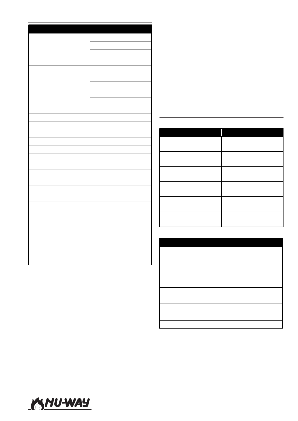
Burner Motor Fails To Start
y
y
s
g
t
t
pp
t
y
y
y
y
y
y
p
y
y
pp
g
y
g
g
g
y
y
y
y
y
p
y
g
y
y
Possible Reason Remed
Reinstate power suppl
No power supply to
burner
Power supply to burner
OK
Gas train disconnected Check and reconnec
Appliance controls
incorrectl
set
Gas supply isolated Restore suppl
Low gas pressure Check and rectif
Low gas pressure
switch incorrectl
set
Air pressure switch not
in start
osition
Fuel selector switch
incorrectl
set
Oil line ball valve
incorrectl
set
Valve proving system
locked out
Oil preheater limit
thermostat tri
ed
Low oil temperature
To check that the air pressure switch is in the "start"
position:
1 Switch off the electrical power supply to the
burner.
2 Remove the plug-in assembly from the con-
trol box base.
3 Using a suitable instrument, check for elec-
trical continuity between the following terminals:
Satronic TMG 740 Terminals 16 and 17
Landis & Staefa LFL 1.333 Terminals 13 and
14.
Check fuse
Check burner correctly
wired
Check appliance
controls callin
for hea
Check burner not
locked ou
Check motor overload
not tri
ed
Check and adjust as
necessar
Check and adjust as
necessar
Check as below
Check and reset
Check and reset
Check and reset
Check and rectify
Check thermostat
settin
4 If the air pressure switch is not in the start
position turn the setting dial clockwise fully
to the maximum setting. Check again for
continuity between the above terminals. If
there is no continuity the pressure switch is
faulty and should be renewed.
If a gas booster is fitted:
1 Ensure that the low inlet gas pressure switch
is not locked out.
2 Check that the booster drive belt is fitted.
3 Verify that the booster motor is rotating cor-
rectly.
Fan Starts And Burner Goes To Lockout
(1) No Ignition
Possible Reasons Remed
Air pressure switch
settin
Ignition electrode
settin
Cracked electrode
insulation
HT lead disconnected
or dama
Ignition transformer
fault
Programming controller
fault
s incorrect
s incorrect
ed
Possible Reasons Remed
Gas supply isolated
ressure too low Investigate and remed
Gas
Air flow incorrect for
as flow
Valves fail to open
Manual isolation valve
closed
Carbon on diffuser Clean
Reset
Reset
Renew electrode
Reconnect or renew as
necessar
Renew electrode
Check and renew as
necessar
(2) No Flame - Gas Firing
Check gas supply to
burner
Check and adjust as
necessar
Check wiring, replace
valves if fault
Open valve
Models NDF35 to NDF150
Page 53
Page 54
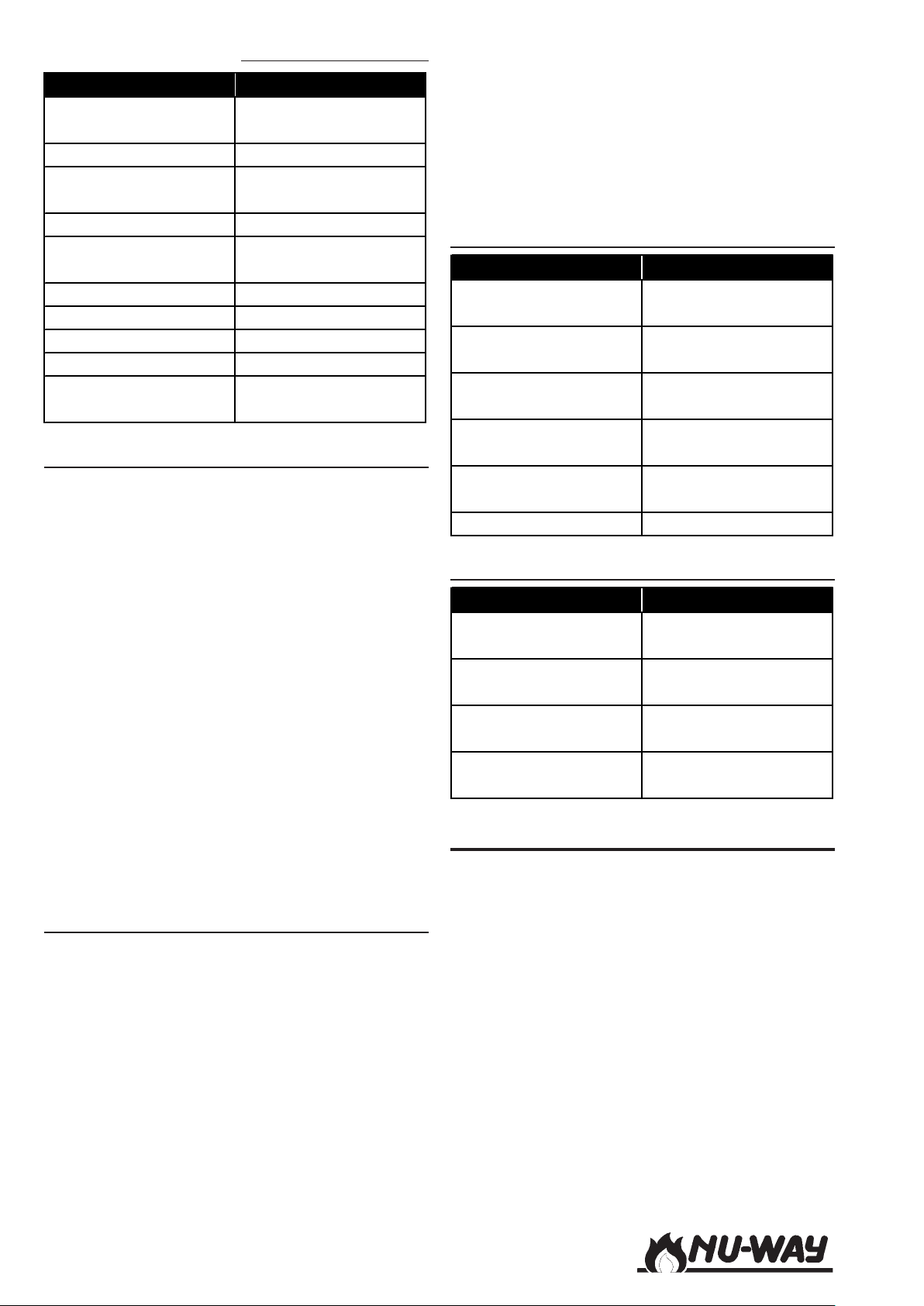
(3) No Flame - Oil Firing
y
p
p
y
y
y
p
p
y
p
y
y
y
y p
g
t
y
g
y
Possible Reasons Remed
Oil supply interrupted
Pum
coupling failed Replace
Pump drive motor (if
fitted) failed
Oil
ressure too low Investigate and remed
Valves fail to open
Oil pump fault
Filter blocked Clean or re
Nozzle blocked Clean or re
Carbon on diffuser Clean
Oil temperature too
low
Check oil supply to
burner
Check wiring, fuses
etc.
Check wiring, replace
valves if fault
Replace
lace
lace
Check and rectify
Start Flame Failure
Failure of the start rate flame will produce lockout.
Confirm start flame failure by checking the flame
signal at the appropriate stage. If the flame signal
is low, the cause may be:
1 A dirty or wrongly positioned (it must face
towards the flame) glass envelope on the UV
cell.
2 A fault in the UV cell or its wiring - check
and replace if necessary.
3 The flame signal check link has been re-
moved - check and replace.
4 There is insufficient fuel under ignition con-
ditions to allow the flame to be detected
adequately - adjust the flow rate.
5 Partial blockage of the oil nozzle - check and
clean if necessary.
6 Carbon on the air diffuser - check and clean
if necessary.
Incorrect Rotation Of Burner Motor
The motor should rotate anti-clockwise as viewed
from the motor end. If the direction of rotation is
incorrect interchange two phases in the threephase power supply. If this does not correct the
direction of rotation the motor should be renewed.
If it is necessary to change this motor or the combustion air fan the following procedure should be
followed:
1 Switch off the burner and the electrical power
supply to the burner.
2 Disconnect the multi-pin plug from the
socket on the control system.
3 Remove the screw which holds the control
system to its mounting bracket.
4 Lift the control system from its mounting
bracket and rest it on the gas valve train.
5 The securing studs, fixing nuts and bolts on
the mounting flange are now readily accessible.
Main Flame Is Not Established
Possible Reasons Remed
Fuel pressure or flow
too low
Main gas/oil valve fails
to o
en
Programming controller
fault
Low fire hold link
removed
Gas train gasket
incorrectl
Air settin
ositioned
incorrect Rese
Check fuel supply to
burner
Check wiring, replace
valve if fault
Check and renew as
necessar
Replace link
Reposition
Burner Motor Only Runs Continuously
Possible Reasons Remed
Air control damper
motor failed
Air control damper cam
loose
Microswitch fails to
chan
eover
Damper motor
incorrectl
wired
Renew
Tighten
Renew
Rewire
SPARE PARTS
For spare parts contact Nu-way's Parts And Components Division at the address and telephone
number listed on the rear cover of this manual. To
avoid delays, please provide the burner model and
serial numbers.
Models NDF35 to NDF150Page 54
Page 55
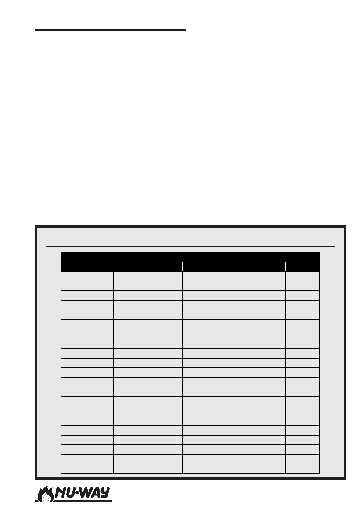
APPENDIX
C
This appendix contains additional information and
documentation including:
- Burner head details and dimensions
- Electrode setting details
- Burner performance envelopes
- Commissioning sheets (oil and gas). Blank
sheets are provided which must be filled in
by the engineer on completion of commissioning.
For two stage (high/low) burners the pressure,
combustion quality and temperature data
should be obtained for both high and low
fire settings for both oil and gas firing.
For fully modulating burners additional data
at intermediate positions in the operating
range between high and low fire are required.
A copy of the completed sheet must be sent
to the appliance manufacturer.
- Burner service record sheets , to enable the
user to maintain a service history
- Blank ëNotesí pages, to allow the user to
make any relevant notes, comments or other
relevant information.
Burner Head Dimensions (accompanies drawings on Pages 56 and 57)
Model
AB
NDF35-25 178 171 149 70 6 6.0
NDF35-34 178 171 149 70 6 6.0
NDF35-38 178 171 149 70 6 6.0
NDF50-28 219 206 190 89 8 9.5
NDF50-34 219 206 190 89 8 9.5
NDF50-38 219 206 190 89 8 9.5
NDF60-28 219 206 190 89 8 9.5
NDF60-34 219 206 190 89 8 9.5
NDF60-38 219 206 190 89 8 9.5
NDF80-28 254 228 203 89 8 9.5
NDF80-34 254 228 203 89 8 9.5
NDF85-38 254 228 203 89 8 9.5
NDF100-38 254 228 203 89 8 9.5
NDF100-41 305 279 248 89 8 12.7
NDF100-44 305 279 248 89 8 12.7
NDF125-36 305 279 248 89 8 12.7
NDF125-41 305 279 248 89 8 12.7
NDF125-44 305 279 248 89 8 12.7
NDF150-36 305 279 238 89 8 12.7
NDF150-41 305 279 238 89 8 12.7
NDF150-44 305 279 238 89 8 12.7
Dimension
DNo. E F
Models NDF35 to NDF150
Page 55
Page 56
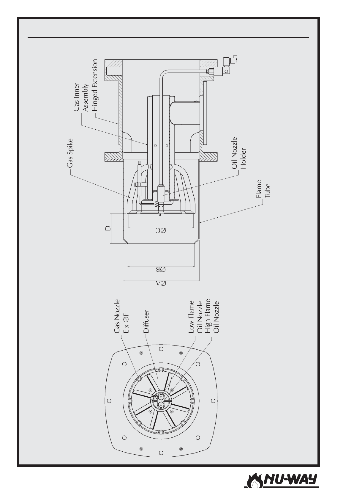
Burner Head Details : Twin Pressure Oil Jet Models
Models NDF35 to NDF150Page 56
Page 57
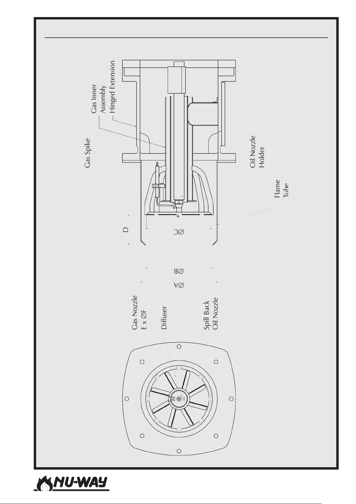
Burner Head Details : Single Spill Back Oil Nozzle Models
Models NDF35 to NDF150
Page 57
Page 58
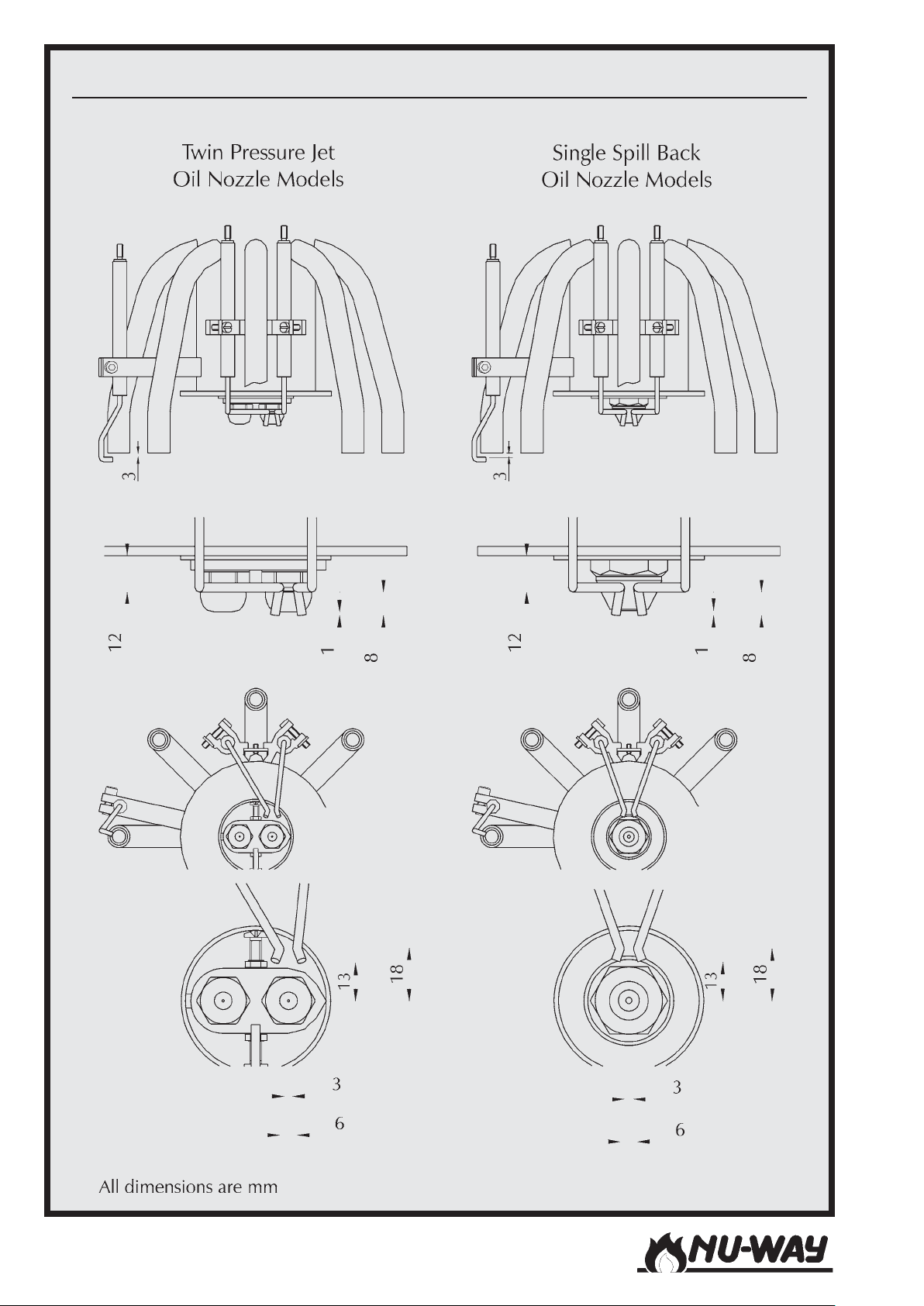
Electrode Setting Detail
Models NDF35 to NDF150Page 58
Page 59
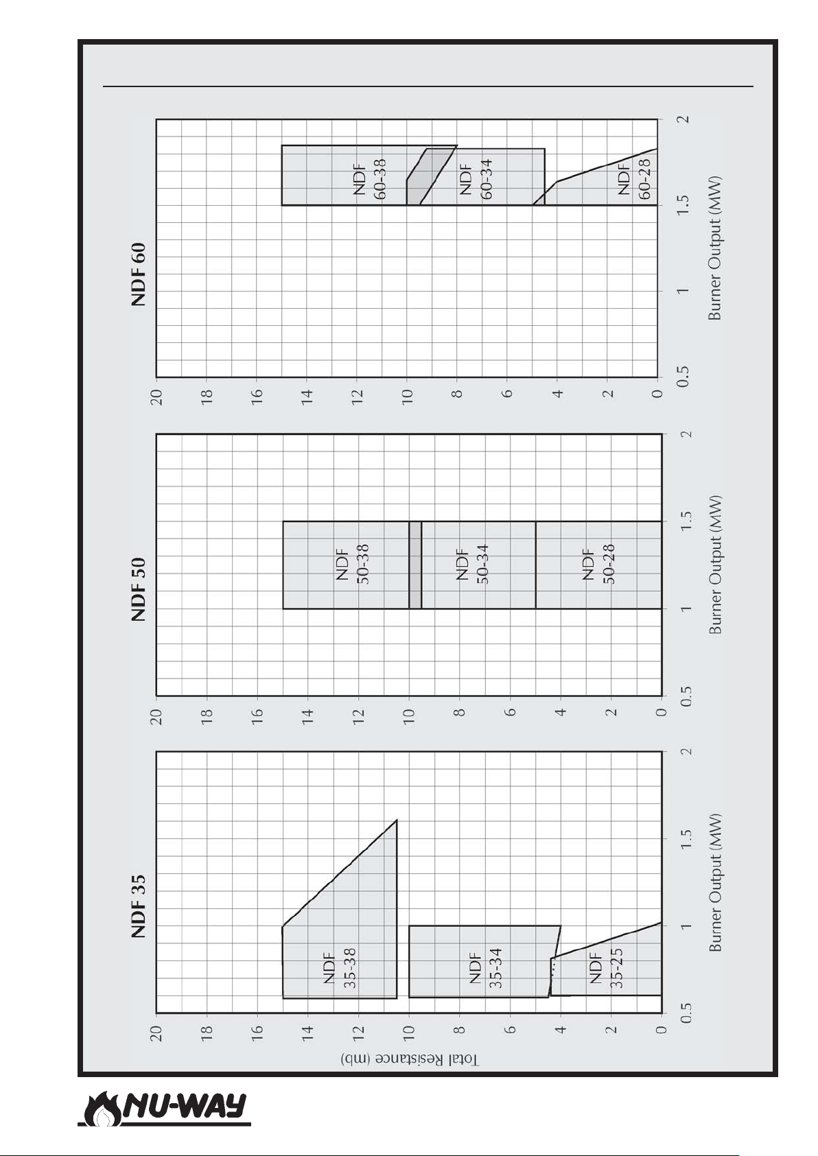
Performance Envelopes : NDF 35, NDF 50 And NDF 60
Models NDF35 to NDF150
Page 59
Page 60
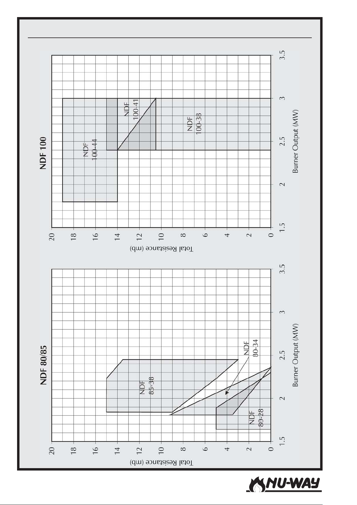
Performance Envelopes : NDF 80/85 And NDF 100
Models NDF35 to NDF150Page 60
Page 61
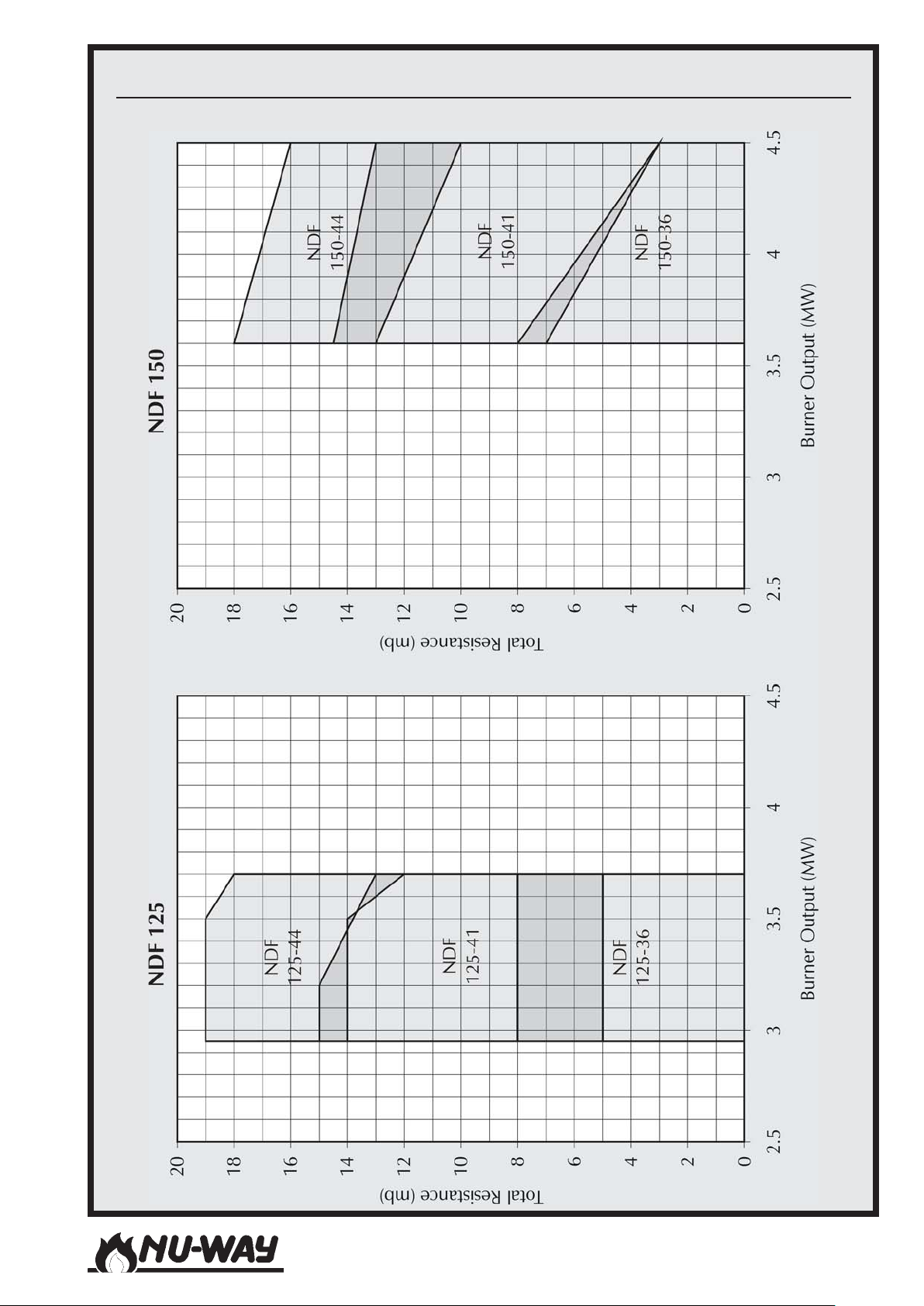
Performance Envelopes : NDF 100 And NDF 150
Models NDF35 to NDF150
Page 61
Page 62
Oil Commissioning Sheet
p
p
The details below are to to be completed by the Commissioning Engineer. The completed sheet
must then be
Installer's Name :
Address :
Site Address :
hotocopied and a copy forwarded to the appliance manufacturer.
Appliance
Burner
Type : Size :
Type : Size :
Serial
Number
Serial
Number
:
:
Commissioning Date :
Guarantee Expiry Date :
Fuel Oil Type :
Oil pressure upstream of pump :
Standing bar or psi Running bar or psi
Firing Rate Intermediate Positions
Pressure
at burner
Oil
Air
High
Fire
Oil rate
Low
Fire
Units
bar or
mbar or
ins w.c.
kg/h or
lb/h
MW or
Heat input
MJ/h or
Btu/h
O
2
CO
2
CO
Flue Temp.
Ambient Temp.
Temp. Difference
% Dry
Basis
% Dry
Basis
ppm Dry
Basis
°C or
°C or
°C or
1
si
°F
°F
°F
Efficiency
1
Note : Where a choice of measurement units is shown, delete those not applicable
Models NDF35 to NDF150Page 62
%
Page 63
Gas Commisioning Sheet
g
p
The details below are to to be completed by the Commissioning Engineer. The completed sheet
must then be
Installer's Name :
Address :
Site Address :
hotocopied and a copy forwarded to the appliance manufacturer.
Appliance
Burner
Type :
Type :
Size :
Size :
Commissioning Date :
Guarantee Expiry Date :
Fuel Gas Type :
Gas pressure upstream of main governor :
mbar or ins w.g. mbar or ins w.g.Standing Running
Firing Rate
Pressure
at burner
Gas
Air
High
Fire
Gas rate
Heat input
O
2
CO
2
CO
Flue Temp.
Ambient Temp.
Temp. Difference
Intermediate Positions
Serial
Number
Serial
Number
:
:
Low
Fire
1
Units
mbar or
ins w.
mbar or
ins w.c.
3
/h or
m
3
MW or
MJ/h or
Btu/h
% Dry
Basis
% Dry
Basis
ppm Dry
Basis
°C or
°F
°C or
°F
°C or
°F
.
Efficiency
1
Note : Where a choice of measurement units is shown, delete those not applicable
Models NDF35 to NDF150
%
Page 63
Page 64

BURNER SERVICE RECORD
reenignEgnicivreSehtybdetelpmoceboterawolebsliatedehT
cebotteehssihT
etaDecivreSfOsliateDerutangiS
tnemtsujda/ecivreshcaegniwollofdengisdnadetelpmo
Models NDF35 to NDF150Page 64
Page 65

BURNER SERVICE RECORD
reenignEgnicivreSehtybdetelpmoceboterawolebsliatedehT
cebotteehssihT
etaDecivreSfOsliateDerutangiS
tnemtsujda/ecivreshcaegniwollofdengisdnadetelpmo
Models NDF35 to NDF150
Page 65
Page 66

NOTES
Models NDF35 to NDF150Page 66
Page 67

NOTES
Models NDF35 to NDF150
Page 67
Page 68

Enertech Limited,
P O Box 1,
Vines Lane
Droitwich,
Worcestershire,
WR9 8NA
 Loading...