

Page 1

Installation & Maintenance Manual
MDFL 760
MDFL 1070
Dual Fuel Burner
Page 2

Contents
1. General information............................................................................................................. 3
2. Scope of delivery.................................................................................................................. 3
3. Maintenance and customer service..................................................................................... 3
4. Operating instructions .......................................................................................................... 3
5. Instruction of operating personnel ....................................................................................... 3
6. Filter/Strainer........................................................................................................................ 3
7. Key for code designation ..................................................................................................... 4
8. Technical specifications........................................................................................................ 4
9. Boiler connection dimensions .............................................................................................. 4
10. Ignition electrode .................................................................................................................. 5
11. Flame failure controller......................................................................................................... 5
12. Oil connection....................................................................................................................... 6
13. Oil pump ...............................................................................................................................8
14. External oil pump (option) .................................................................................................... 8
15. Front panel ........................................................................................................................... 9
16. Air flap positioning motor ..................................................................................................... 9
17. Remote switching .................................................................................................................9
18. Air pressure switch ............................................................................................................10
19. Gas pressure monitor......................................................................................................... 10
20. Functional control ...............................................................................................................10
21. Start-up............................................................................................................................... 11
22. Troubleshooting / process description ................................................................................15
23. Control unit ........................................................................................................................19
24. MPA 22 control unit display ................................................................................................19
25. Calculation principle for gas burner adjustment ................................................................ 20
26. Gas train KEV
1 ½" , KEV 2" and KEV DN65 ..................................................................21
II
27. Gas train KEV25 1" and KEV30 1½".................................................................................. 22
28. Nozzle selection diagram ...................................................................................................23
29. Adjustment tables............................................................................................................... 24
30. Exploded views / spare parts lists .....................................................................................25
31. Adjustments log.................................................................................................................. 32
32. Declaration of conformity for dual-fuel burner for heating oil
and natural gas or liquid gas ..............................................................................................33
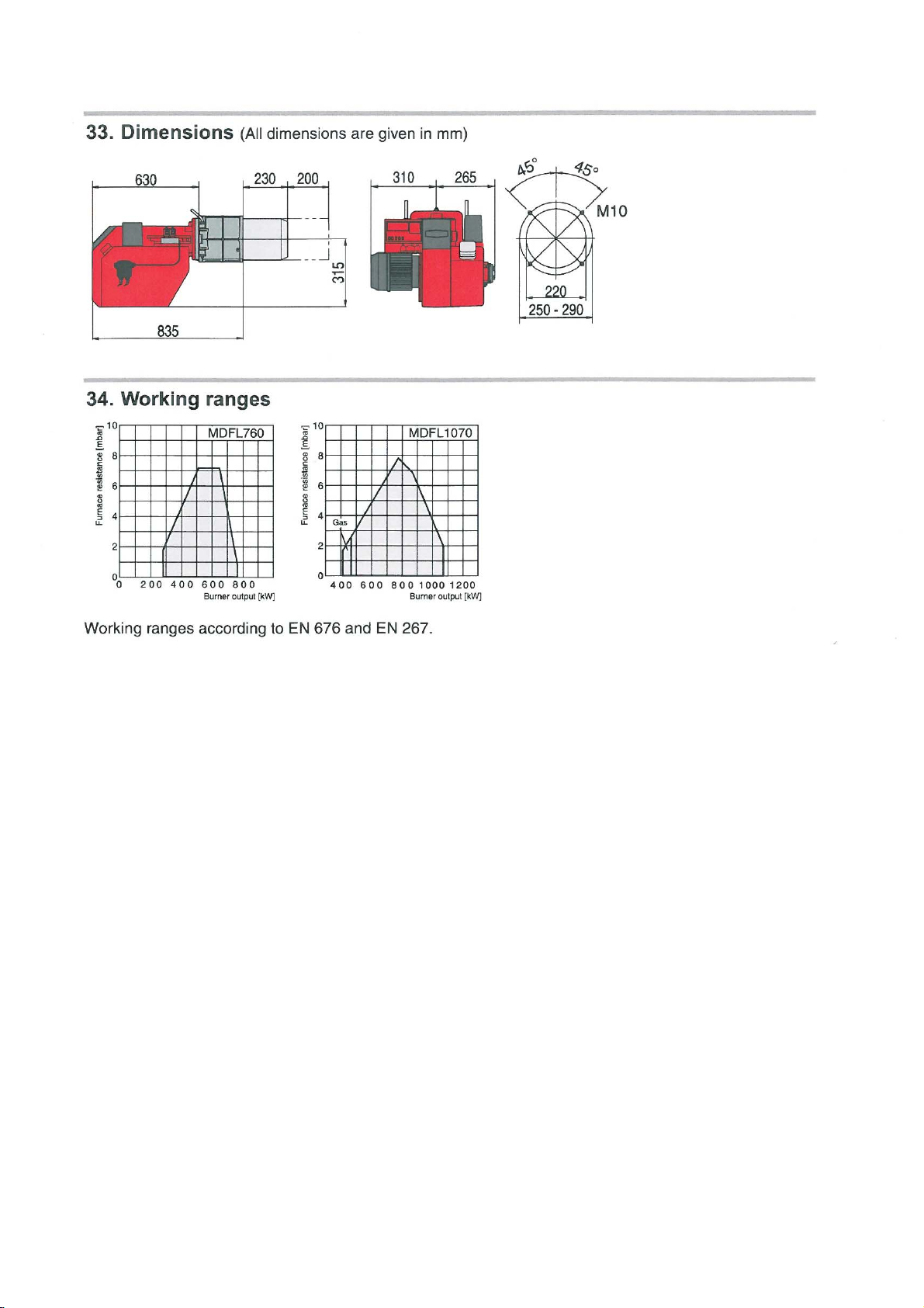
33. Overall dimensions ............................................................................................................ 34
34. Working ranges .................................................................................................................. 34
2
E. 30.07.07 • G. 07.06.11
Page 3

1. General information
Installation of a dual fuel burner must be performed in accordance with extensive regulations and guidelines. It is therefore the duty of the installer to be familiar with all applicable regulations and requirements.
Installation, start-up and maintenance must be performed with utmost care.
The burner must not be operated in rooms with high levels of air humidity (laundry rooms), dust or corrosive
vapours. The boiler room must be ventilated accordingly with ventilation air.
Light oil in accordance must be used. The burners are suitable for combustion of natural gas or liquid gas
and are in compliance with European standard EN 676 and 267.
2. Scope of delivery
Before installing the Nu-Way Series MDFL760/1070 dual fuel burner, please check that all the items included in the scope of delivery are present.
Scope of delivery:
burner, mounting kit, separate operating instructions, technical information, separate circuit diagram, flange
seal, one 7- pin connector and one 4- pin plug connector (Wieland connector).
Caution !
Oil nozzles are not included in the scope of delivery.
For gas:
Gas train
The gas pipe must be designed to conform to the flow rate and the available gas flow pressure and routed
with the lowest pressure loss over the shortest distance to the burner.
The loss of gas pressure via the gas train and the burner as well as the resistance on the fuel gas side of
the heat generator must be less than the connection flow pressure.
Caution !
Observe sequence and throughflow direction of fittings
3. Maintenance and customer service
The complete system should be checked once a year for correct functioning and leaks in accordance with
DIN 4755 by a representative of the manufacturer or other suitably qualified person.
According to EN 267 it is not permissible to perform repairs on components with a safety function. On the
other hand, the replacement of parts with genuine parts or approved equivalent parts is permitted.
We accept no liability for consequential damage in cases of incorrect installation or repair, the fitting of nongenuine parts or where the equipment has been used for purposes for which it was not intended.
4. Operating instructions
The operating instructions together with this technical information leaflet must be displayed in a clearly visible position in the boiler room. The address of the nearest customer service centre must be displayed on
the back of the operating instructions.
5. Instruction of operating personnel
Faults are often caused by operator error. The operating personnel must be properly instructed in how the
burner works. In the event of recurring faults, Customer Service should be notified.
6. Filter/Strainer
According EN 676 a filter/strainer shall be fitted at the inlet of the safety shut-off valve to prevent the ingress
of foreign elements.
E. 30.07.07 • G. 07.06.11
3
Page 4
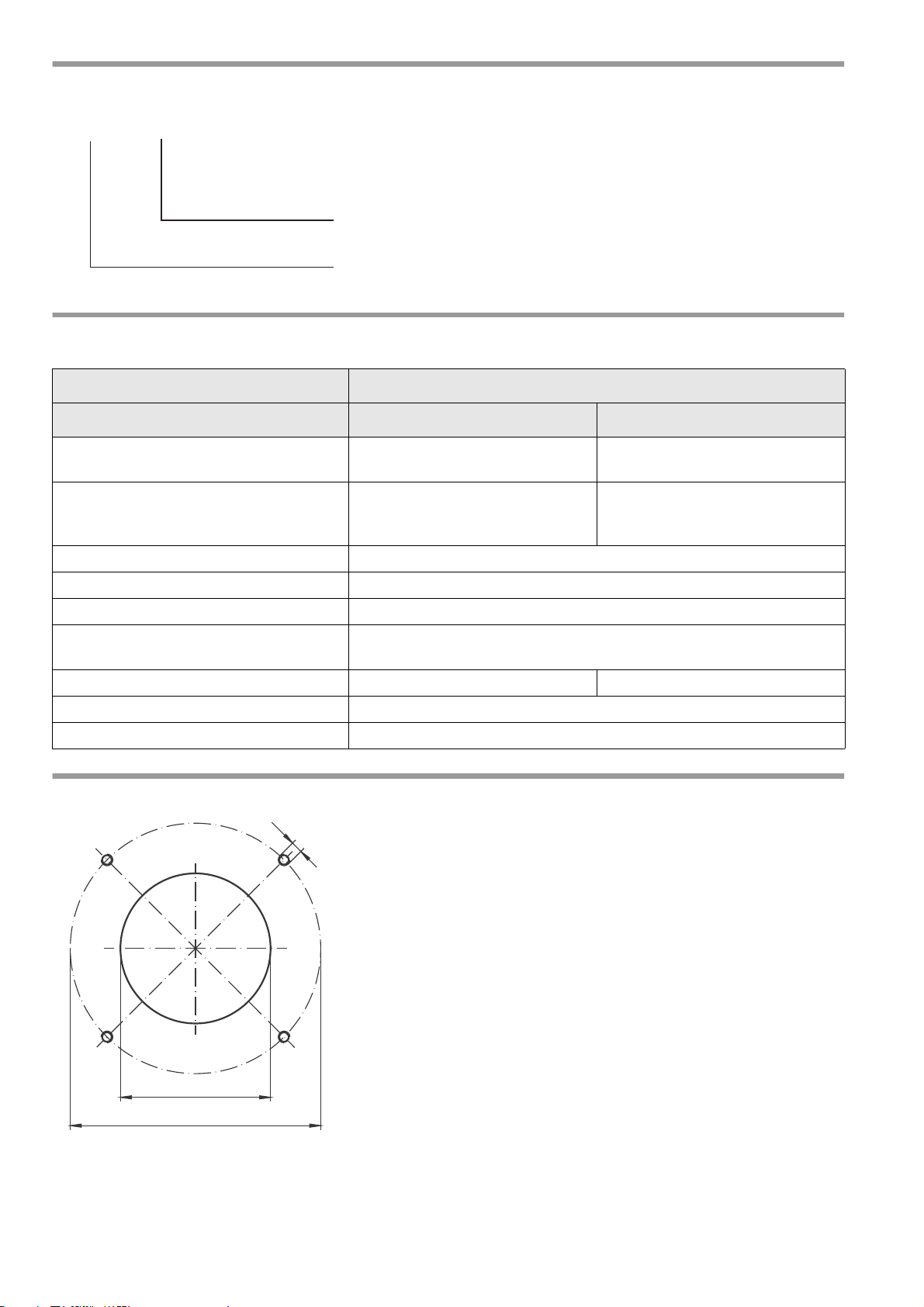
7. Key for code designation
MDFL760
Burner output max.
Series
M10
Ø220
Ø250 - 290
8. Technical specifications
Burner type
Technical specifications MDFL760 MDFL1070
Burner output in kW
(in gas-fired operation)
Burner output (in oil-fired operation)
in kg/h
(in kW)
Fuel Light oil, natural gas LL + E, LPG
Mode of operation Optionally oil/gas two-stage or gas modulating, oil two-stage
Voltage 3 / N / PE ~ 50 Hz / 400 V
Power consumption at start / during opera-
tion
Electric motor power (at 2800rpm) in kW 1.1 2.2
Flame failure controller KLC 1000
Control box MPA 22
9. Boiler connection dimensions
280 - 760 415 - 1070
23.6 - 64.1
(280 - 760)
6.5 A max./ 3.6 A eff.
(All dimensions are given in mm)
(469 - 1070)
39.5 - 90.2
E. 30.07.07 • G. 07.06.11
4
Page 5
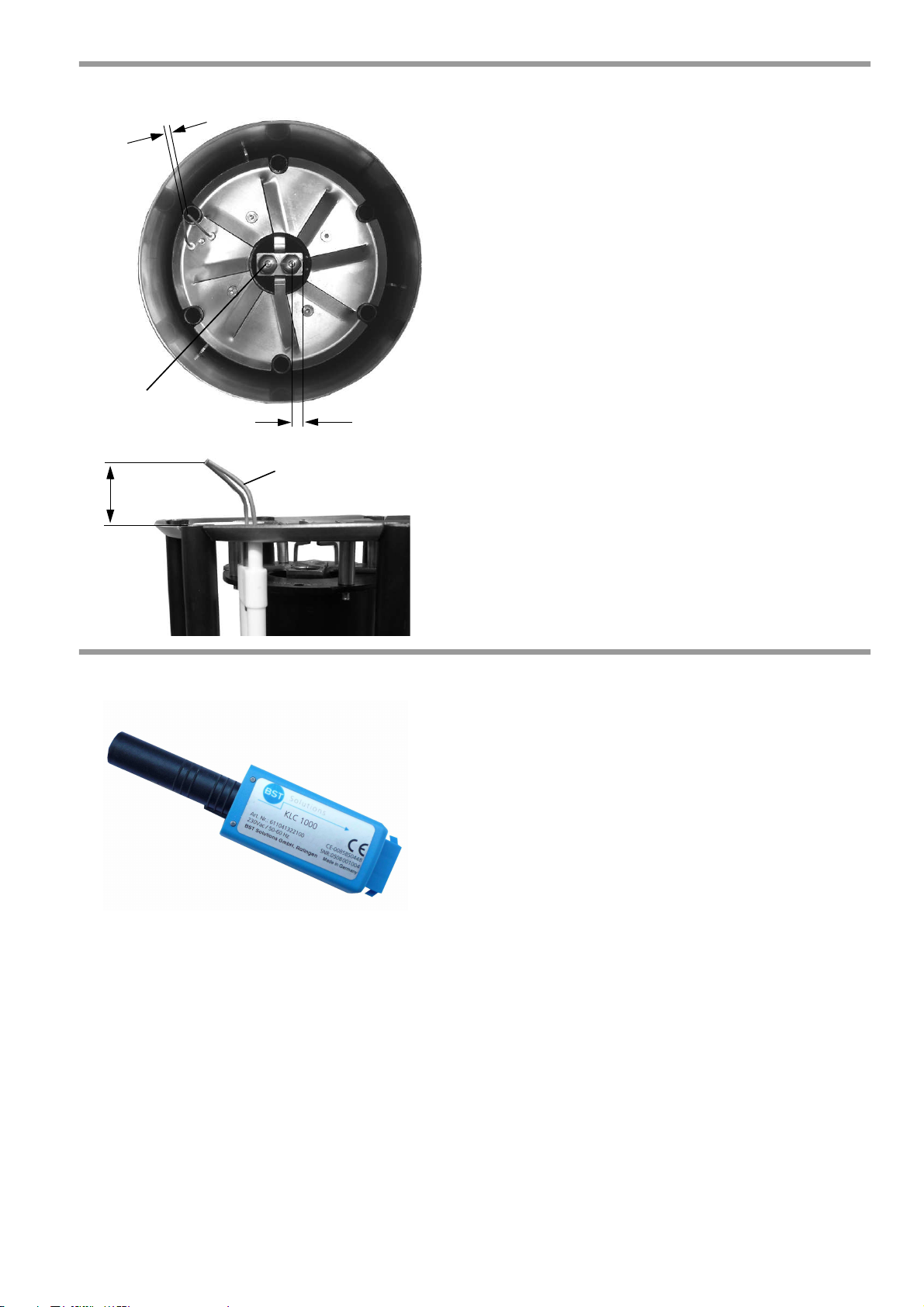
10. Ignition electrode
4
m
m
27 mm
13 mm
Gas ignition electrode
Oil ignition electrode
The following clearances between the nozzle and ignition
electrode should be observed:
The given dimensions are intended for checking purposes after making necessary corrective adjustments or replacing an electrode.
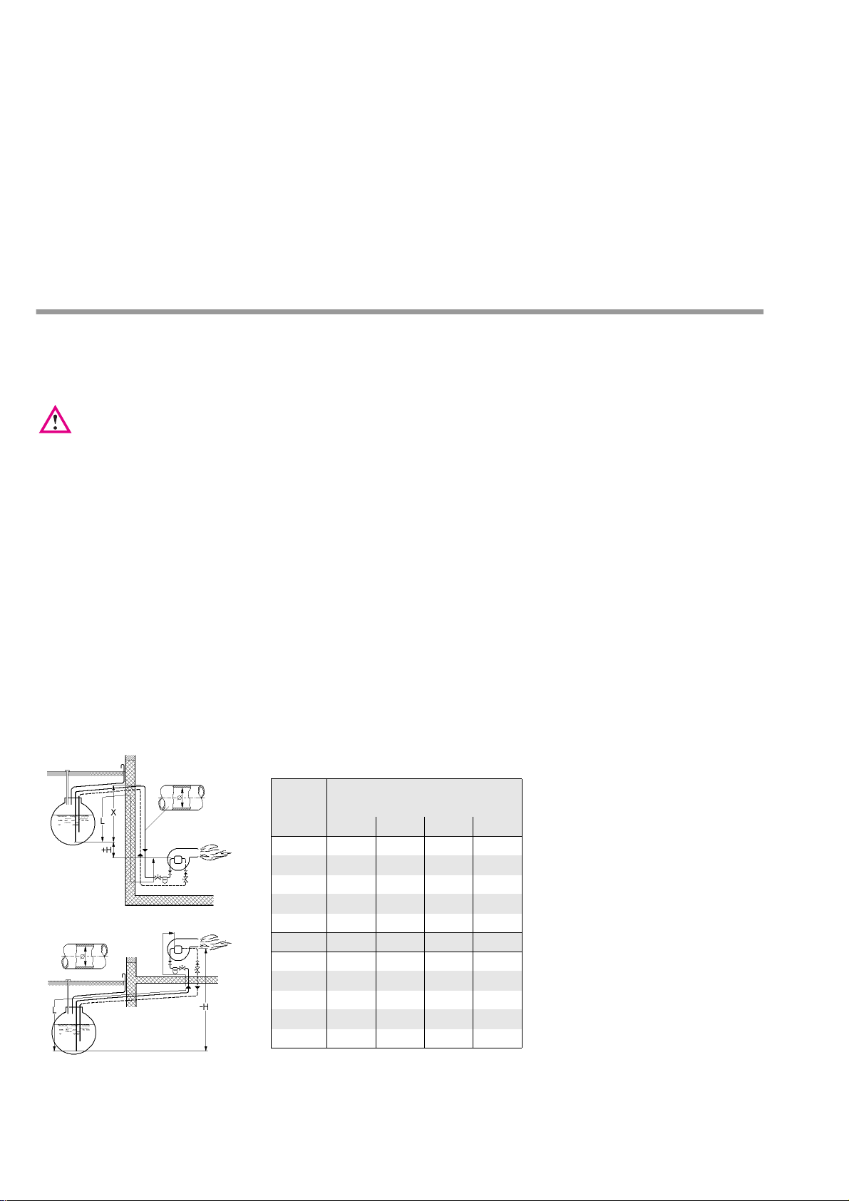
11. Flame failure controller
Commissioning and maintenance
The installation and commissioning must be done by qualified personnel only. Before energising the KLC
flame detector please check the cable and wiring connections are in accordance to the diagram and instructions given above. For good maintenance which will ensure trouble free operation of the KLC flame
detector; please keep the sight glass clean by wiping with a soft dry clean cloth. Warning: Do not use any
kind of cleaning sprays or fluids. During commissioning and after any cleaning maintenance, the flame detector should be checked, as the UV tube is subject to a natural ageing process and towards the end of its
life span it is prone to malfunction.
Operating Indicator LED:
LED is OFF: KLC is not switched on – no power supply
or ‘no flame’ is detected.
LED is FLASHING: KLC has detected a flame; the quality of the flame signal is indicated by the intensity of the
flashing of the LED – fast flashing indicates a healthy
flame signal and vice versa - slow flashing indicates a
weak flame signal.
LED is ON: KLC has detected the strongest level of
flame signal.
To check that the flame detector is sound we recommend the following procedures be followed:
• Start the burner with the fuel supply closed-off or remove the flame detector from its mounting flange
and cover the UV tube using a soft cloth to avoid touching the glass lens. The control box will lock-out
at the end of the safety time due to absence of a flame signal.
E. 30.07.07 • G. 07.06.11
5
Page 6
• Remove the flame detector from its mounting flange. Start the burner while exposing the flame detector to an external UV radiation source such as a cigarette lighter flame, or a small gas flame (n.b. electric room lighting or a torch is inadequate). The burner Control Box must go to lock-out due to
detecting an extraneous light source either immediately or at the end of the air pre-purge cycle,
depending on the type/model of the Control Box.
• Close off the fuel supply or remove flame detector from its mounting flange and cover the UV tube
using a soft cloth when the burner is in the "run" position. The control box must go immediately to
lock-out resulting in the burner shutting down.
If any of these safety checks do not function as described i.e. they should always result in burner shutdown
and control box lock-out; then it is essential to replace the flame detector with a new KLC flame detector.
For safety and trouble free burner operation, we recommend that the flame detector should be replaced
after every 10,000 hours of burner operation or approximately every 30months for a burner operating on
an average of 10 hours per day.
12. Oil connection
Oil lines must be routed to the burner as far as necessary to allow the oil hoses to be connected without
tension. Care must be taken to ensure that the burner can easily be moved into the service position.
Important: an oil filter must be installed before the oil pump.
The tables for single and double line installation show the maximum possible pipe length in dependence
on 3 factors with reference to heating oil type EL 4.8 cST.
• Height differential between pump and tank,
• nozzle delivery rate or pump type,
• pipe diameter.
4 brackets, 1 valve and 1 check valve for resistance were factored into the suction line length. Due to possible degassing of the oil, dimension "X" should not exceed a length of 4 m.
To convert the pump for operation on a single line system, the following points must be observed:
remove the return line and the connection nipple. Unscrew the bypass plug in the return line port and tightly
seal the port with a sealing plug. The pump suction flow will then be identical to the flow rate through the
nozzle.
Double line system
Suntec AJ4
H (m) L (m)
∅ mm 10 12 14 16
4.0 23 49 91 100
3.0 20 43 80 100
2.0 17 37 69 100
1.0 14 31 58 100
0.5 13 28 53 91
0 11 25 47 81
-0.5 10 22 42 72
-1.0 9 19 36 62
-2.0 6 13 25 43
-3.0 3 7 14 24
-4.0 - - - 5
E. 30.07.07 • G. 07.06.11
6
Page 7
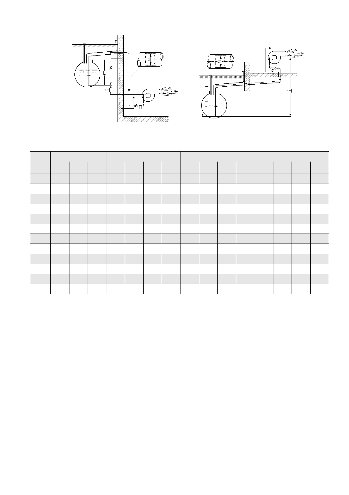
Single-pipe system
Nozzle 14 (gph) 20 (gph) 30 (gph) 45 (gph)
.∅ mm 8 10 12 8 10 12 14 10 12 14 16 10 12 14 16
H (m) L (m) L (m) L (m) L (m) L (m) L (m) L (m) L (m) L (m) L (m) L (m) L (m) L (m) L (m) L (m)
4.0 21 52 100 14 36 75 100 23 49 92 - 15 32 61 100
3.0 18 45 95 12 31 66 100 20 43 81 - 13 28 53 92
2.0 16 39 82 11 27 57 100 17 37 70 - 11 24 46 79
1.0 13 33 69 9 23 48 89 15 31 59 - 9 20 38 66
0.5 12 30 62 8 20 43 81 13 28 53 - 8 18 35 60
0 11 27 56 7 18 39 72 12 25 48 82 7 16 31 54
-0.5 9 23 49 6 16 34 64 10 22 42 72 - 14 27 47
-1.0 8 20 43 5 14 30 55 9 19 36 63 - 12 23 41
-2.0 5 14 30 3 10 21 39 6 13 25 44 - 8 16 28
-3.0 3 8 17 - 5 11 22 3 7 14 25 - 4 8 15
-4.0 - - 4 - - - 5 - - - 5 - - - -
E. 30.07.07 • G. 07.06.11
7
Page 8
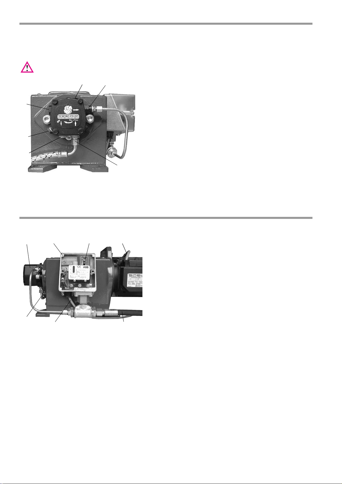
13. Oil pump
6
5
2
1
3
4
1
2
3 4
5
6
7
Oil lines must be routed to the burner as far as necessary to allow the oil hoses to be connected without
tension. Care must be taken to ensure that the burner can easily be moved into the service position.
Important: an oil filter must be installed before the oil pump.
Suntec oil pump
1 Supply
2 Return
3 Nozzle connection
4 Pressure gauging connection
5 Vacuum gauging connection
6 Pressure setting
To change over the pump for single line operation, the following points should be noted:
disconnect return line and remove connecting nipple. Unscrew the bypass plug in the return line port and
tightly seal the port with a sealing plug. The pump suction flow will then be identical to the flow rate through
the nozzle.
14. External oil pump (option)
1 Three-phase a.c. motor connecting cable
2 Oil pump power cord
3 Oil pressure switch connecting cable
4 Pressure line to burner
5 Oil pressure switch
6 Oil pressure setting screw
7 Oil pump
The external oil pump is supplied for burners which primarily
operate in gas burning mode.
In oil burning mode, the pump starts when a heating request
is issued. Oil pressure switch (5) is fitted for pressure monitoring. In the event of loss of oil pressure, the burner shuts
off automatically. The oil pressure switch is pre-set at the factory. Pressure can be adjusted using the setting screw (6).
E. 30.07.07 • G. 07.06.11
8
Page 9
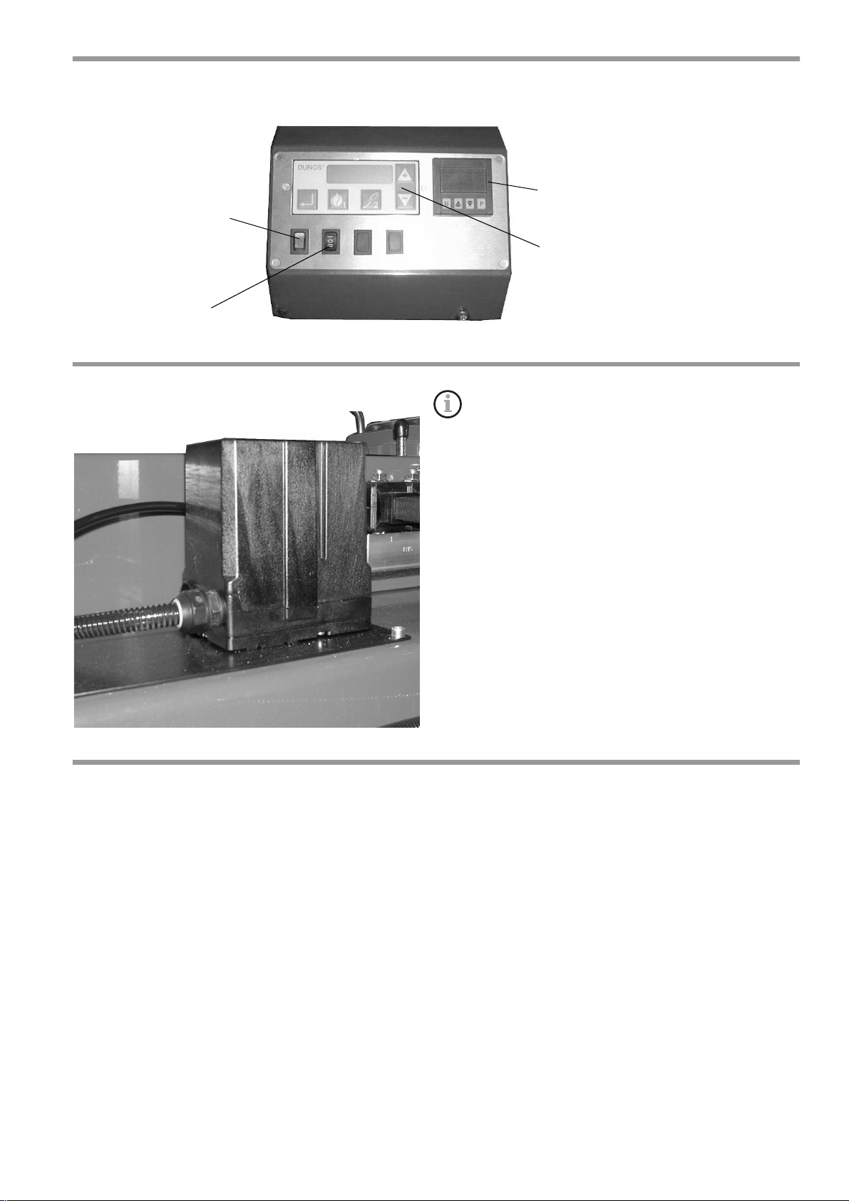
15. Front panel
Controller (option)
Display and operating unit AM01
On/Off
Selector switch
Oil operation/gas-fired operation
16. Air flap positioning motor
The air flap positioning motor is designed for air flap
adjustment on progressive two-stage burners or modulating burners. The motor is activated electronically
via the microprocessor-controlled control box.
17. Remote switching
Note
If the selector switch under the burner hood is in the "Remote" position, it is not possible to change over
between oil and gas operation with the selector switch on the front panel.
It is only possible to change over between oil and gas operation if the selector switch under the burner hood
is in the "Manual" position.
E. 30.07.07 • G. 07.06.11
9
Page 10
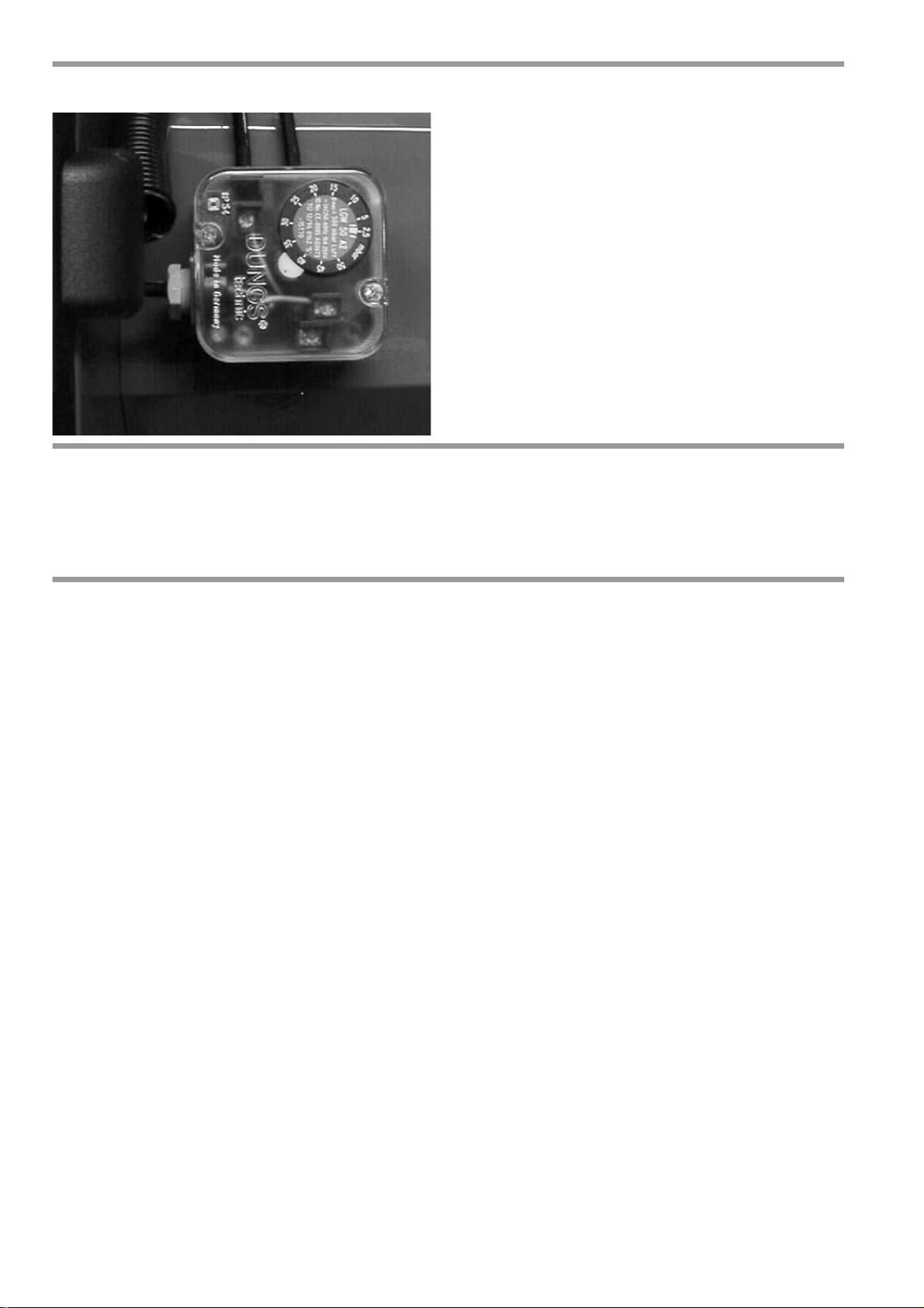
18. Air pressure switch
The air pressure switch is a differential pressure switch
and monitors pressure at the forced-air burner.
The air pressure switch is preset at the factory to
8 mbar.
19. Gas pressure monitor
The gas pressure monitor serves to monitor the gas inlet pressure. The burner is shut down if the gas inlet
pressure drops below the set minimum value (preset at factory). The burner starts up automatically again
when the minimum pressure is exceeded.
20. Function test
The flame monitor must undergo a safety test both at initial start-up and after modifications or if the system
has been out of use for a lengthy period of time.
Start-up test with blacked-out flame sensor:
The burner must go into lockout mode after expiry of the safety interval.
Start-up with exposed flame sensor:
The burner must go into lockout mode after approx. 20 s of pre-ventilation.
Normal start-up; if the burner is in operation, black out the flame sensor:
repeat start-up test, the burner must go into lockout mode after expiry of the safety interval.
10
E. 30.07.07 • G. 07.06.11
Page 11
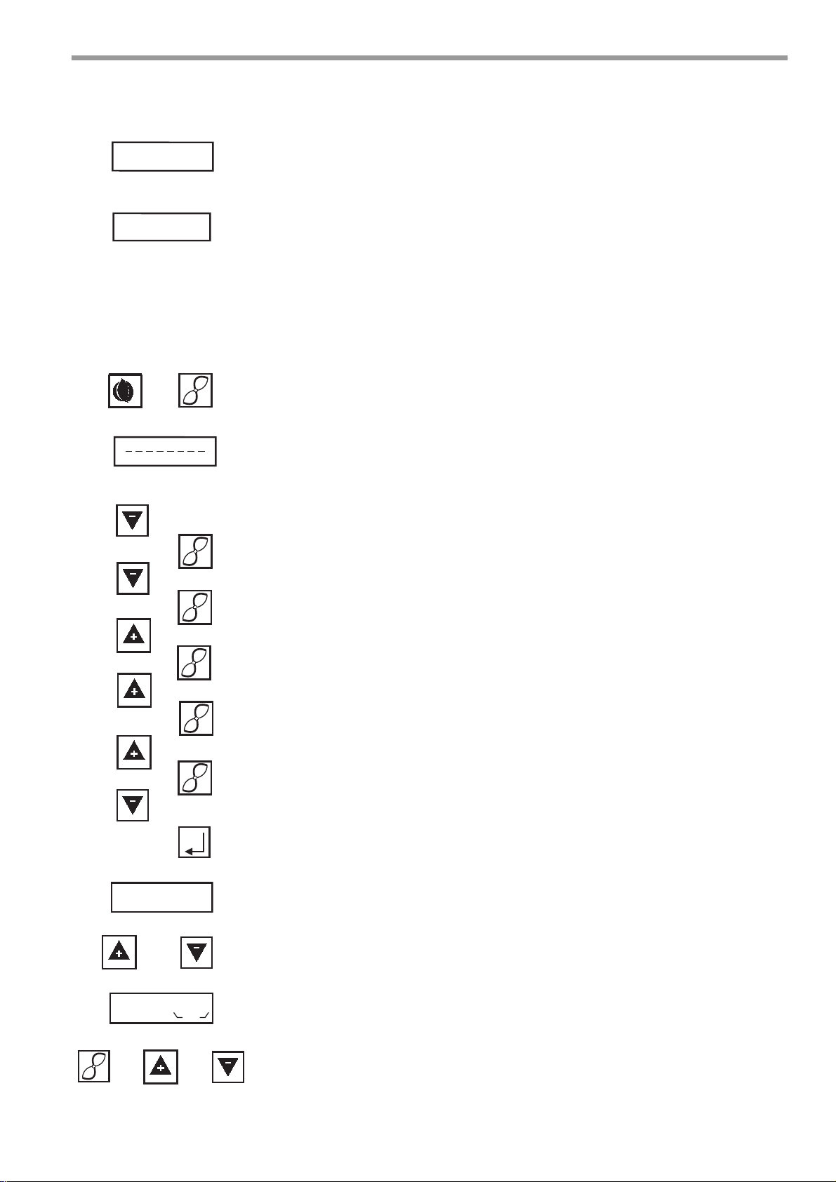
21. Commissioning:
1
2
OFF
OFFUPr
2
2
2
2
2
or
or
2
and
E OIL
P
9 OIL
P
L/A
Adjustment mode - oil-fired operation
To enter this adjustment mode, the burner must be on standby.
Standby means that the burner is connected to the power supply, but no heating request has been issued and the burner is switched to oil-fired operation. If
OFF appears on the display on MPA 22, the unit is running in standby mode
and has already been configured.
If OFFUPr appears on the display, the MPA 22 is also running in standby mode,
but the unit is still unprogrammed and all setting parameters still have to be entered by the following procedure.
Important: If the setting operation is interrupted within 30 min. or not completed correctly, OFFUPr will also be displayed.
To change new setting parameters or old setting parameters, follow these
steps:
Step 1:
Enter the safety code. Press key 1 and key 2 simultaneously
Step 2:
7 horizontal bars are now displayed. Enter the password as follows.
Note: The intervals between the individual inputs must not be longer than 20
sec., as the MPA 22 will otherwise revert to standby mode. If this is the case,
you will have to start the code entry procedure from the beginning again.
- Press the minus key twice.
- Confirm your entry by pressing key 2 once.
- Press the minus key once.
- Confirm your entry by pressing key 2 twice.
- Press the plus key 4 x.
- Confirm your entry by pressing key 2 once.
- Press the plus key twice.
- Confirm your entry by pressing key 2 once.
- Press the plus key 3 x.
- Confirm your entry by pressing key 2 once.
- Press the minus key 4x.
- Press the enter key once.
Password entry is now finished.
Step 3:
after the correct password has been entered, EOIL appears on the display.
Step 4:
the operating points 9OIL (stage 3), 3OIL (stage 2) and 1OIL (stage 1) can
now be selected by pressing the plus or minus key.
E. 30.07.07 • G. 07.06.11
Step 5:
After Stage 3 has been selected, 9OIL appears on the display. The Stage 3 operating point can be adjusted to values between 0° and 90° by holding down
key 2 and optionally pressing the plus or minus key.
Note: The setting value of Stage 3 should be set to a value 0.1° greater than
the value of Stage 2!
11
Page 12
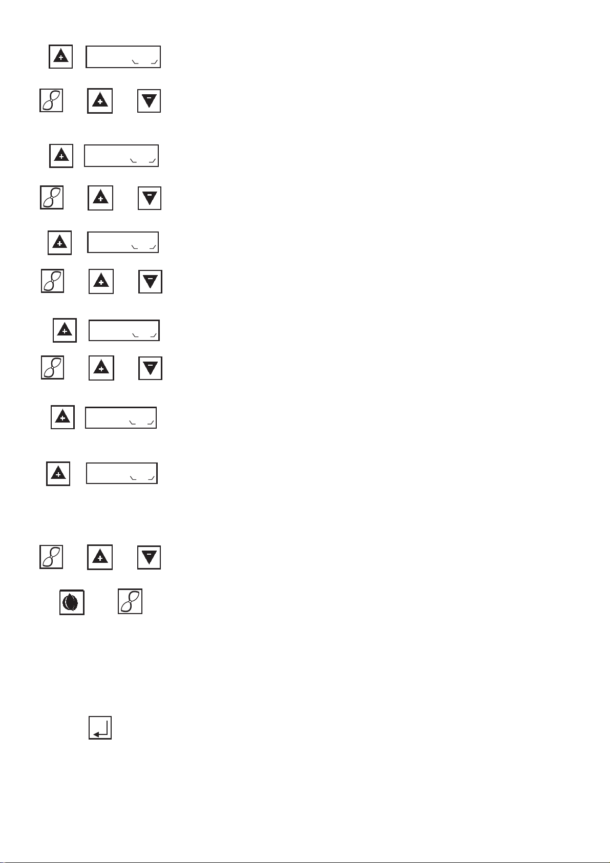
Step 6:
or
2
and
or
2
and
3 OIL
P
L/A
1 OIL
L/A
P
or
2
and
or
2
and
0 OIL
P
L/A
2 OIL
P
L/A
0 OIL
P
L/A
4 OIL
P
L/A
1
2
or
2
and
and
After you have set Stage 3, press the plus key to set Stage 2 . 3OIL appears
on the display.
The Stage 2 operating point can be adjusted to values between 0° and 90° by
holding down key 2 and optionally pressing the plus or minus key.
For basic setting values, please refer to the adjustment table.
Step 7:
After you have set Stage 2, press the plus key to set Stage 1. 1OIL. appears
on the display.
The Stage 1 operating point can be adjusted to values between 0° and 90° by
holding down key 2 and optionally pressing the plus or minus key.
For basic setting values, please refer to the adjustment table.
Step 8:
After you have set Stage 1 , press the plus key to set the ignition point P0.
0OIL. appears on the display.
The ignition point P0 can be adjusted to values between 0° and 90° by holding
down key 2 and optionally pressing the plus or minus key.
Step 9:
After you have set the ignition point P0 , press the plus key
to set the Stage 1 / 2 switch-over point. 2OIL. appears on the display.
The Stage 1 / 2 switch-over point can be adjusted to values between 0° and 90°
by holding down key 2 and optionally pressing the plus or minus key.
Step 10:
After the Stage 1 / 2 switch-over point has been set, press the plus key. 4OIL
of the Stage3 / 3 switch-over point appears on the display. The setting value
should be at Stage 3. Press the plus key again. OIL.
Appears on the display.
Close the safety loop. The burner should now start up and dwell in the ignition
position. If this is not the case, please repeat the procedure for adjustment of
the ignition point under Step 8.
Step 11:
The setting values are now adjusted in relation to the boiler and the required
burner output. The burner is in operation throughout the adjustment procedure
so that all boilers and measured data relevant to the burner can be recorded.
Adjust the operating points in the order Stage 1, Stage 2, Stage 3 (0.1° greater
than Stage 2), Stage 1 /2 switch-over point, Stage 3 / 4 switch-over point (0.1°
greater than Stage 2) and make adjustments by simultaneously pressing key
2 and the plus or minus key. To switch the burner to normal operation, press
key 1 and key 2 simultaneously for approximately 2 sec. The burner switches
to Stage 1 and then returns to normal operation. The setting procedure is now
completed and the values have been stored.
Note:
If you want to change values after finishing the setting procedure, you will have
to start from the beginning again, i.e. OFF.
Note: faults are cleared by pressing the enter key.
E. 30.07.07 • G. 07.06.11
12
Page 13
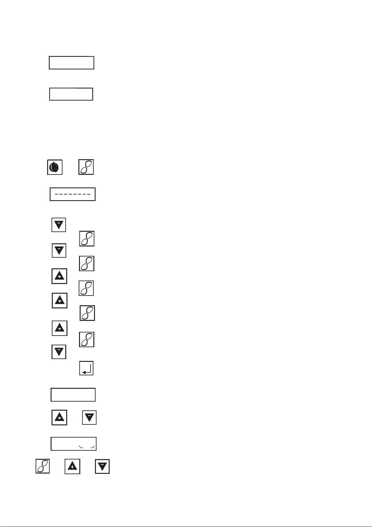
Adjustment mode - gas-fired operation
1
2
OFF
OFFUPr
2
2
2
2
2
or
2
and
or
GAS Pn
P
9GAS
P
L/A
To enter this adjustment mode, the burner must be on standby.
Standby means that the burner is connected to the power supply, but no heating request has been issued and the burner is switched to gas-fired operation.
If OFF appears on the display on MPA 22,
the unit is running in standby mode and has already been configured.
If OFFUPr appears on the display, the MPA 22 is also running in standby mode,
but the unit is still unprogrammed and all setting parameters still have to be entered by the following procedure.
Important: If the setting operation is interrupted within 30 min. or not completed correctly, OFFUPr will also be displayed.
To change new setting parameters or old setting parameters, follow these
steps:
Step 1:
Enter the safety code. Press key 1 and key 2 simultaneously
Step 2:
7 horizontal bars are now displayed. Enter the password as follows.
Note: The intervals between the individual inputs must not be longer than 20
sec., as the MPA 22 will otherwise revert to standby mode. If this is the case,
you will have to start the code entry procedure from the beginning again.
- Press the minus key twice.
- Confirm your entry by pressing key 2 once.
- Press the minus key once.
- Confirm your entry by pressing key 2 twice.
- Press the plus key 4 x.
- Confirm your entry by pressing key 2 once.
- Press the plus key twice.
- Confirm your entry by pressing key 2 once.
- Press the plus key 3 x.
- Confirm your entry by pressing key 2 once.
- Press the minus key 4x.
- Press the enter key once.
Password entry is now finished.
Step 3:
after the correct password has been entered, EGAS Pn appears on the display.
Step 4:
the operating points P9 (max load), P1 (min load) and P0 (starting point)
can now be selected by pressing the plus or minus key.
E. 30.07.07 • G. 07.06.11
Step 5:
After the operating point P9 has been selected, 9GAS appears on the display.
The max load operating point can be adjusted to values between 0° and 90° by
holding down key 2 and optionally pressing the plus or minus key.
For basic setting values, please refer to the adjustment table.
13
Page 14
or
2
and
or
2
and
1GAS
P
L/A
0GAS
P
L/A
GAS Pn
P
or
2
and
0GAS
P
L/A
or
1GAS
P
L/A
or
2
and
or
or
2
and
9GAS
P
L/A
1
2
and
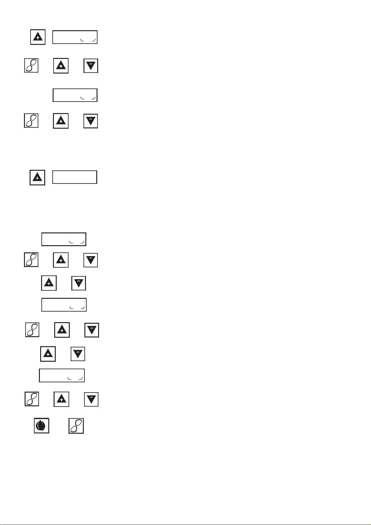
Step 6:
After you have set P9, press the plus key to set P1. 1 Gas appears on the display.
The min load operating point can now be set to a value between 0° and 90° by
holding down key 2 and optionally pressing the plus or minus key.
For basic setting values, please refer to the adjustment table.
Step 7:
After you have set P1, press the plus key to set P0 (the starting point). 0 Gas
appears on the display.
The operating point (starting point) can now be set to a value between
0° and 90° by holding down key 2 and optionally pressing the plus or minus
key. The value of P1 should preferably be set. If P1, (min. load) is set to a very
low value, it is recommended to set P0 to a higher value than P1 in order to
ensure stable starting.
For basic setting values, please refer to the adjustment table.
Step 8:
After you have set P0, press the plus key.
GAS Pn. appears on the display.
Now close the safety loop and issue a heating request.
The burner should now start up and dwell in the ignition position. If this is not
the case, please repeat the procedure for adjustment of ignition point P0 under
Step 7. After the burner has started up, the gas train must be set to the nozzle
pressure specified in the adjustment table.
Step 9:
The setting values are now adjusted in relation to the boiler and the required
burner output. The burner is in operation throughout the adjustment procedure
so that all boilers and measured data relevant to the burner can be recorded.
Adjust the operating points in the order P0,P1 and P9 and make adjustments
by simultaneously pressing key 2 and the plus or minus key. To switch the
burner to normal operation, press key 1 and key 2 simultaneously for approximately 2 sec. The burner switches to min output P1 and then returns to normal
operation.
The setting procedure is now completed.
Note:
If you want to change values after finishing the setting procedure, you will have
to start from the beginning again.
E. 30.07.07 • G. 07.06.11
14
Page 15
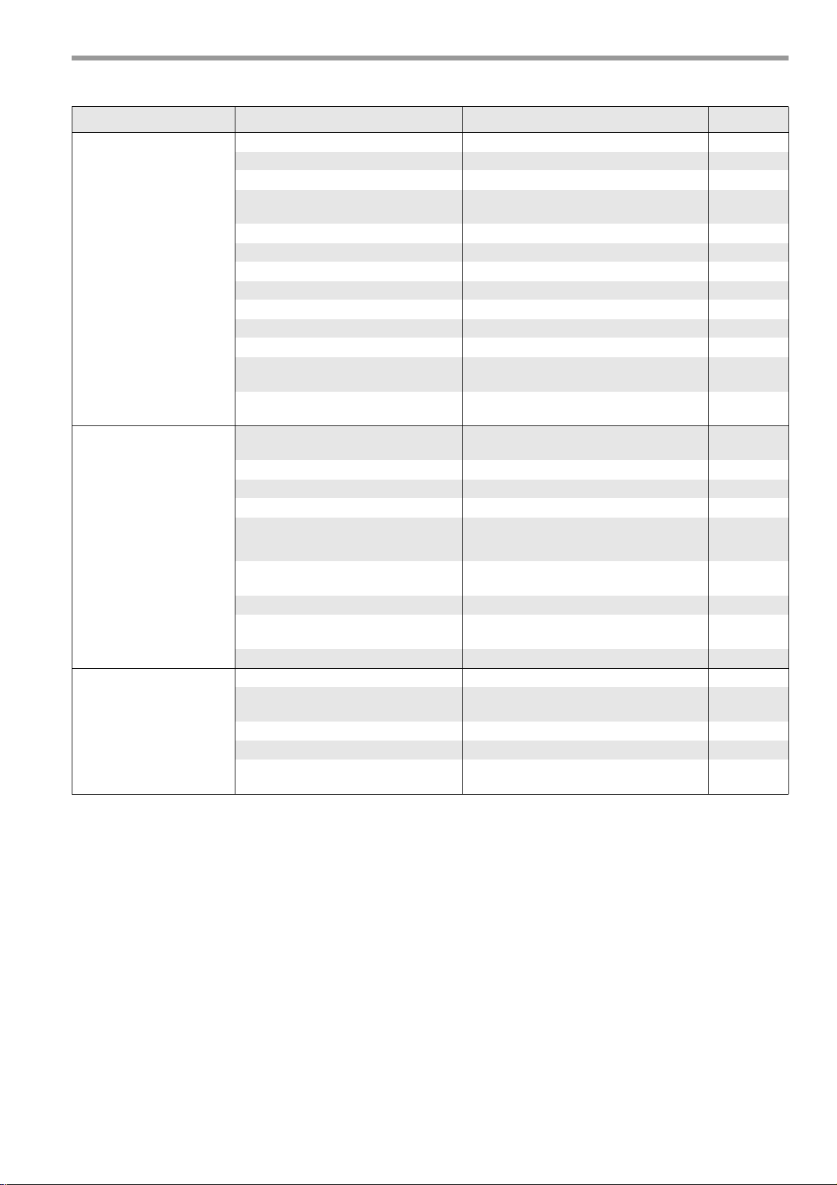
22. Troubleshooting / process description
Defect determined: Cause: Remedy: Fault code
Burner motor does
not start up
Burner starts up and
switches to fault mode
before or after expiry of
safety period
Electric supply lead faulty Rectify faults in electrical installation
Fuse faulty Replace
Safety thermostat locked Unlock 42 h
Temperature of controller setting is
exceeded
MPA 22 faulty Replace 04 h
Leak Rectify leak 44H / 43H
No gas Safeguard gas supply
Gas pressure monitor faulty Replace gas train 22 h
Filter in gas train dirty Clean or replace
Air pressure switch not in idle position Check air pressure switch (see page 9) 20 h
Burner motor faulty Replace
No load at terminal 5 Check plug connection and current path of
Mains voltage < 187 V
Air pressure switch does not switch
through during pre-ventilation
Ignition influencing of ionization monitor See Page 10 26 h
Gas solenoid valve does not open Replace gas train
Starting gas quantity set too low Increase starting gas quantity
No ignition Check ignition electrode and setting, igni-
Renewed start attempt after temperature
drop
solenoid valve
Rectify faults in electrical
installation
See Page 9 21 h
tion transformer and cable
Flame extinguishes
during operation
Phase and zero mixed up Connect connector unit in correct phase
sequence
Flame control faulty Check according to Page 10 2BH
Air pressure switch opens during opera-
tion
Gas nozzle dirty or faulty Replace gas nozzle
No gas Safeguard gas supply
Filter in gas train
dirty
Flame blow-off Incorrect burner setting 27 h
Air pressure switch contact opens Check/replace air pressure switch 21 h
Flame signal too weak Measure flame signal, check ionisation
See Page 9 21 h
Clean or replace
27 h
electrode
E. 30.07.07 • G. 07.06.11
15
Page 16
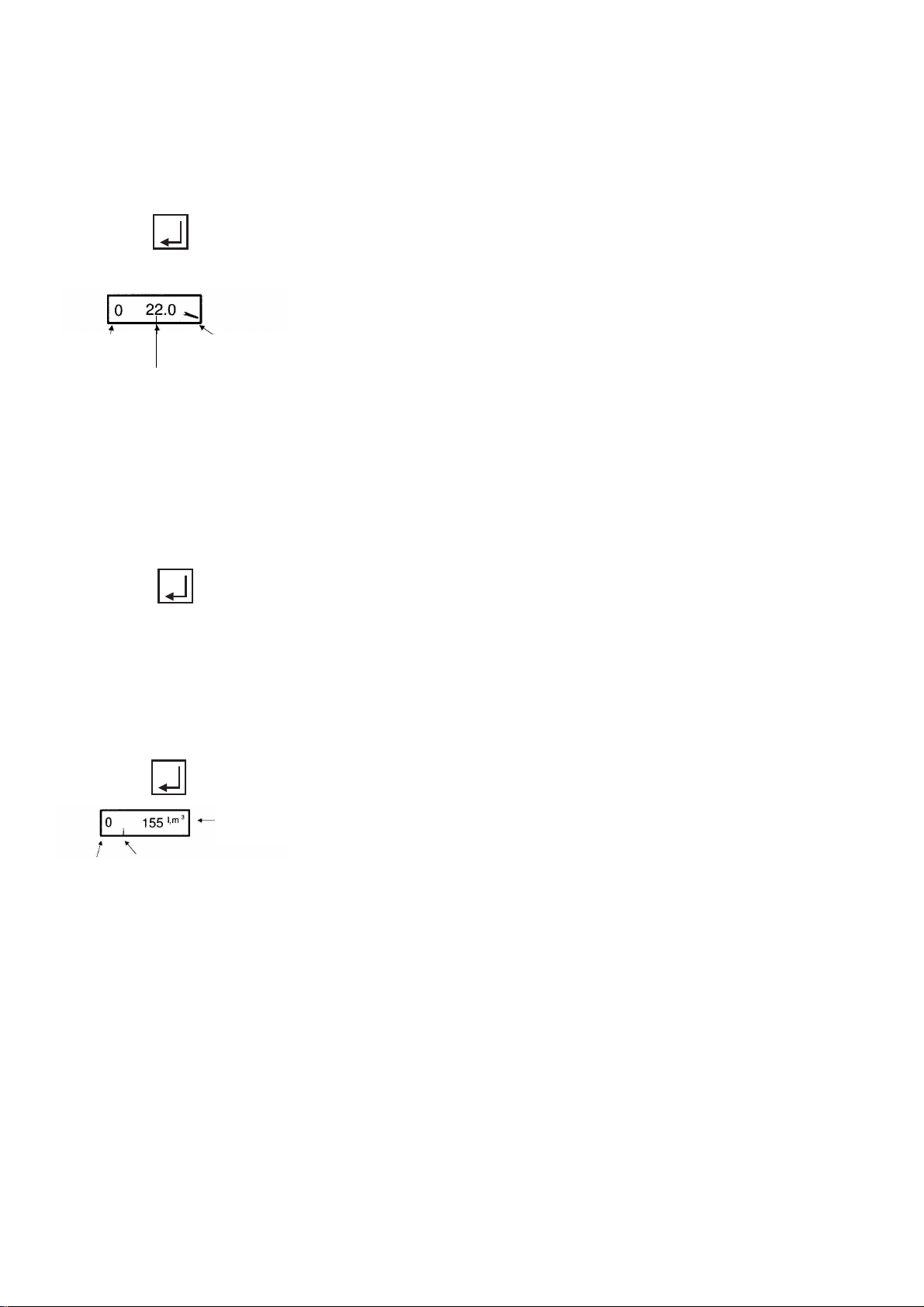
Service mode - pneumatic gas-fired operation
Adjustment
point
Adjustment
values
Service mode
symbol
Adjustment
point
Information mode symbol
display
value
The service mode serves to display the set parameters and to read out the fault memory. It can be invoked
in any operating state of the burner.
Important:
setting values cannot be changed in service mode. If no key is pressed for longer than 20 sec., the
display returns to standby mode.
To access the service mode, press the enter key for approx. 2 sec.
The following now appear on the display: point P0 and the air flap positioning motor setting value at ignition in angular degrees, plus a wrench
symbol denoting the service mode.
The following points can be retrieved by repeatedly pressing the enter
key:
- The characteristic curves for points P0, P1 and P9
- The last 6 fault messages P10 to P15 (see fault code MPA)
- The testing times of the valve proving system P16 and P17
- The flame quality P18
- The eBus address of the MPA P19
- The switch setting of the valve proving system P21
- The eBus address of the external controller P24
- The modulation delay
- The set start points P26
To exit the service mode, please press the enter key or wait approx.
20 sec.
Information mode
The information mode is intended for display of consumption figures, operating hours and software data.
To access information mode, press the Enter key for approx. 0.5 sec.
A zero and a value appear on the display.
The following values can be queried in information mode under setting
points 0 to 8. Retrieve by repeatedly pressing the enter key:
Important:
If no key is pressed for longer than 20 sec., the display returns to
normal operating mode.
0 = fuel consumption
1 = total operating hours
2 = for oil only
3 = for oil
only 4 = number of successful start-ups
5 = display of software version
6 = software creation date
7 = hardware number
8 = date of production
E. 30.07.07 • G. 07.06.11
16
Page 17

Troubleshooting the MPA
Code Description
04 h Internal hardware fault
05 h Internal hardware fault
06 h Internal hardware fault
07 h Internal hardware fault
09 h Internal hardware fault
10 h Internal hardware fault
11 h Internal hardware fault
12 h Internal hardware fault
13 h Internal hardware fault
14 h Internal hardware fault
15 h Internal hardware fault
20 h Air pressure switch is not in idle position
21 h Failure of air pressure switch
22 h Failure of gas pressure monitor
25 h No flame after safety period
26 h Outside light
27 h Flame failure during operation
29 h Internal hardware fault
2AH Internal hardware fault
2BH Short-circuit in photo resistor or internal fault
2CH Internal hardware fault
30 h Internal hardware fault
31 h Internal hardware fault
32 h Internal hardware fault
33 h Internal hardware fault
34 h Internal hardware fault
42 h Safety chain interrupted
43 h Y3 found to be leaking during leak check
44 h Y3 found to be leaking during leak check
45 h Internal hardware fault
46 h Internal hardware fault
47 h Internal hardware fault
48 h Internal hardware fault
4AH Internal hardware fault
5BH Internal hardware fault
4CH Internal hardware fault
4DH Internal hardware fault
4EH Internal hardware fault
50 h Internal hardware fault
51 h Internal hardware fault
52 h Internal hardware fault
53 h Internal hardware fault
54 h Internal hardware fault
55 h Internal hardware fault
56 h Internal hardware fault
57 h Internal hardware fault
58 h Internal hardware fault
59 h Internal hardware fault
E. 30.07.07 • G. 07.06.11
17
Page 18

Code Description
5AH Internal hardware fault
5CH Internal hardware fault
5DH Internal hardware fault
5EH Internal hardware fault
63 h Internal hardware fault
64 h Internal hardware fault
65 h Internal hardware fault
67 h Internal hardware fault
68 h Incorrect feedback from air flap positioning drive
(check connector and cable, actuator drive mounting and air flap mechanism)
6AH Air-flap actuator position is out of tolerance
(check connector and cable, actuator drive mounting and air flap mechanism)
6CH Internal hardware fault
6DH Internal hardware fault
6EH Actuator drive interchanged or incorrectly connected
6FH Burner detection error
70 h Internal hardware fault
71 h Internal hardware fault
73 h Internal hardware fault
74 h Internal hardware fault
75 h Internal hardware fault
76 h Internal hardware fault
77 h Internal hardware fault
78 h Internal hardware fault
79 h Internal hardware fault
Process description
Start-up tests Processor and program memory test / move actuator drives to reference position
State 01 Start-up decision (heating request present)
State 02 Blower idle state check
State 03 Blower start-up
State 04 Preventilation / operation of gas flap actuator over speed range
State 05 Preventilation / activate and test watchdog
State 06 Preventilation / move gas flap actuator to ignition position
State 07 Move air flap actuator to ignition position
State 08 Pre-ignition depending on parameters
State 09 Start-up safety period
State 10 Stabilisation period
State 11 Move positioning drive from ignition point to operating characteristic
State 12 Operation
State 13 VPS - evacuate valve cavity / (post-ventilate)
State 14 Test duration Y2 / (remaining post-ventilation time)
State 15 VPS - fill valve cavity / (remaining post-ventilation time)
State 16 Test duration Y3 / (remaining post-ventilation time)
State 17 Remaining post-ventilation time
State 18 Restart disable time / waiting loop for low gas program
State 20 Standby position
18
E. 30.07.07 • G. 07.06.11
Page 19
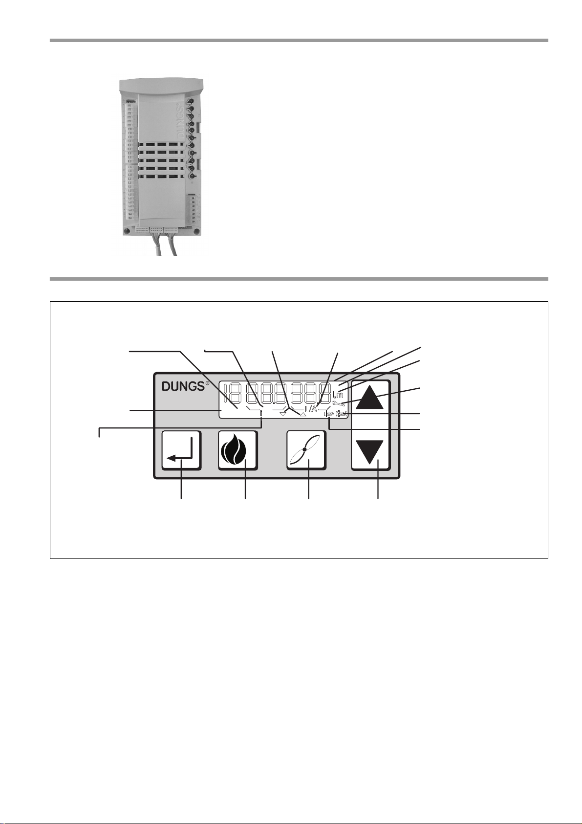
23. Control unit MPA 22
+
–
1
2
P
S
i
G
L/A
h
l,m
3
Acknowledgment or reset
key
Key 1
Actuation of gasflow control flap
in conjunction
with +/- key
Key 2
Actuation of airflow control flap
in conjunction
with +/- key
Key + / Key In conjunction
with key 1 or 2
On when
setup mode
is selected
Start-up
Lights up during
the run-up phase,
OFF during
operation
Lights up when the
gas-flow control
flap is active
On when
information
mode is active
Lights up when the
air-flow control
flap is active
h = Operating hours indicator
l, m3 = Oil or gas consumption
Operation, flame burning
Fault
Lights up when
service mode
is active
Liquid-crystal
display
Symbols for
open/close flaps
24. MPA 22 control unit display
The MPA 22 is a microprocessor-controlled intermittentduty control box for controlling and monitoring pneumatic
modulating forced-air burners with an actuator drive. For
operation as an automatic gas burner control with integral
valve proving system.
The MPA 22 has e-BUS connectivity.
Gas certification
EU type test approval according to EU Gas Appliance
Directive.
MPA 22 CE-0085AU316
E. 30.07.07 • G. 07.06.11
19
Page 20

25. Calculation principles for gas burner adjustment
V
n
Q
n
η
k
H
×
i n,
--------------------
430kW
0 90 10×4
kWh
m
3
-----------
, ,
----------------------------------------= 46
m
3
h
------
= =
V
B
V
n
f
------
46
m
3
h
------
0 94,
-------------= 49
m
3
h
------
= =
f
B P
G
+
1013
--------------
273
273 ϑ
G
+
--------------------
×=
The values given in the tables are setting values for start-up.
The necessary system adjustment must be newly determined in each case.
General:
the calorific value (H
for the normal state (0°C, 1013 mbar).
) of fuel gases is generally specified
i,n
Natural gas type E H
Natural gas type LL H
LPG gas (propane) H
= 10.4 kWh/m
i,n
= 9.3 kWh/m
i,n
=25.89 kWh/m
i,n
3
3
3
Gas counters measure the volume of gas in the operational state.
Gas flow determination:
To allow the heat generator load to be adjusted correctly, the gas flow rate must be determined in advance.
Example:
Altitude above sea level 230 m
Barometric air pressure B (acc. to table) 989 mbar
Gas pressure PG at meter 20 mbar
Gas temperature
Boiler output Q
J
G
n
16°C
430 kW
Efficiency hK (assumed) 90%
Calorific value H
i,n
10.4 kWh/m
3
Gas flow in standard state (Vn)
Gas flow in operating state (V B)
Conversion factor (f)
Annual average air pressure
Average geodetic altitude of the
supply region above sea level [m]
Annual average of air pressure (mbar) 1016 1013 1007 1001 995 989 983 977 971 965 959 953 947 942 936 930
from 1 51 101 151 201 251 301 351 401 451 501 551 601 651 701
to 0 50 100 150 200 250 300 350 400 450 500 550 600 650 700 750
Legend:
Qn = boiler output [kW]
hK = efficiency [%]
H
= lower standard calorific value [kWh/m3]
i,n
f = conversion factor
B = barometric air pressure [mbar]
= gas pressure at gas meter [mbar]
p
G
J
= gas temperature at gas meter [°C]
G
E. 30.07.07 • G. 07.06.11
20
Page 21
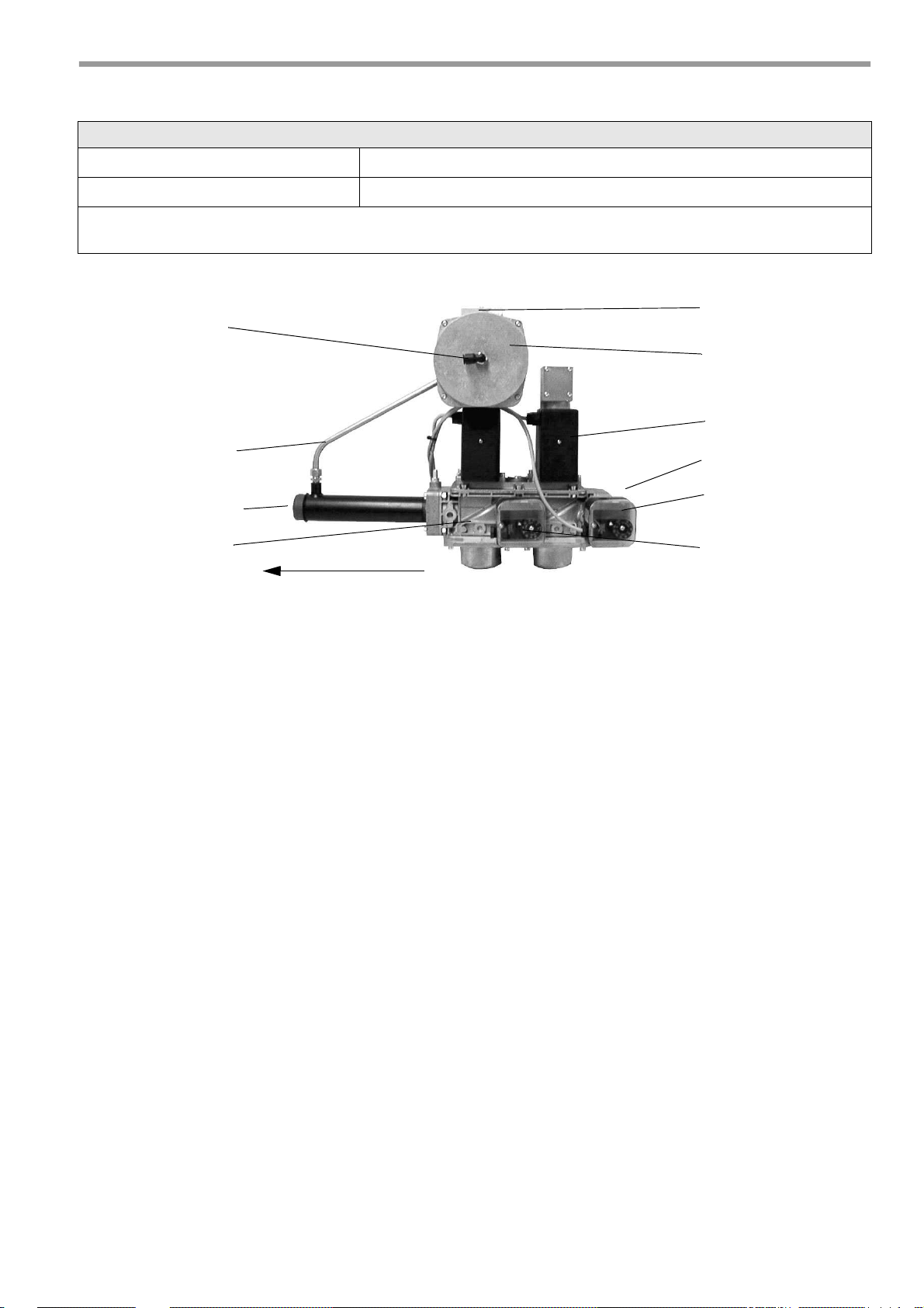
26. Gas train KEV II1 ½" , KEV 2" and KEV DN65
Gas pressure monitor
SKP 10
VGD
Pulse line p
G
SKP 70
Cover plate for
"AIR" air pressure connection
(gas inlet pressure)
Gas pressure monitor
for leak check
Adjustment screws
Direction of flow
Burner
Gas connection
Installing the gas train
Installation position only in horizontal line, not tilted.
Minimum distance to walling: 20 mm
Screw the measuring nipple for combustion chamber pressure into the gas jacket at the top.
Route the connecting hose between the measuring nipple for combustion chamber pressure and the gas train in a loose loop.
The air pressure connection nipple must be screwed into the gas jacket at the top.
Connect the blue hose to the "AIR" connection on the gas train and the air pressure connection on the gas
jacket. The blue hose serves as a control line for the gas train and must be routed in a loose loop without
kinking.
Remove the plate for covering the adjustment screws from the gas pressure regulator.
Start the burner.
1. Setting the air surplus in high and low-load operation
• Set the air flap positions P9 for high-load operation and P1 for low-load operation according to
29. Adjustment tables. Follow the setting procedure described in 19. Adjustment mode for pneumatic
gas-fired operation with MPA 22 display.
• In high-load operation, set the air surplus with the "large flame" adjustment screw on the gas pressure
regulator. The CO2 level in the flue gas should be 9-10% for natural gas.
• In high-load operation, set the air surplus with the "small flame" adjustment screw on the gas pressure
regulator. The CO2 level in the flue gas should be 9-10% for natural gas. The low-load setting influ-
ences the high-load setting.
• In high-load operation, check the air surplus and, if necessary, correct the setting with the "large
flame" adjustment screw on the gas pressure regulator.
2. Setting the output in high and low-load operation
• Check the high-load setting via the gas flow at the gas meter or compare the nozzle pressure with the
values stated in 27. Adjustment tables. The output can be increased by opening the air flap (to
increase P9) and reduced by closing the air flap (to reduce P9). The air surplus is not affected by this
adjustment.
• Check the low-load setting via the gas flow at the gas meter or compare the nozzle pressure with the
values stated in 27. Adjustment tables. The output can be increased by opening the air flap (increase
P1) and reduced by closing the air flap (reduce P1). The air surplus is not affected by this adjustment.
E. 30.07.07 • G. 07.06.11
21
Page 22
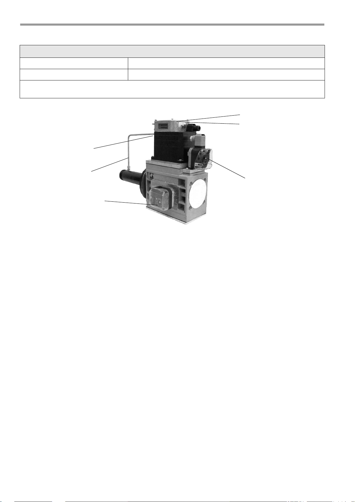
27. Gas train KEV25 1" and KEV30 1½"
Gas pressure monitor
Pulse line p
G
pG
V
N
Gas pressure monitor
for leak check
(gas inlet pressure)
Installing the gas train
Installation position only in horizontal line, not tilted.
Minimum distance to walling: 20 mm
Screw the air pressure measuring nipple into the gas jacket at the top.
Route the connecting hose between the air pressure measuring nipple and the gas train in a loose loop.
The air pressure connection nipple must be screwed into the gas jacket at the top.
The blue hose serves as a control line for the gas train and must be routed in a loose loop without kinking.
Cut the blue hose into two sections. Connect the first sections of blue hose to the "pL" connection on the
gas train and the air pressure connection on the gas jacket, and connect the other section to the "pF" measuring point on the combustion chamber. The hose must be routed in such a fashion that any condensate
forming inside the combustion chamber flows back, and not into the gas train.
Start the burner.
1. Setting the air surplus in high and low-load operation
• Set the air flap positions P9 for high-load operation and P1 for low-load operation according to
29. Adjustment tables. Follow the setting procedure described in 19. Adjustment mode for pneumatic
gas-fired operation with MPA 22 display.
• In high-load operation, set the air surplus at the adjustment screw "V" on the gas pressure regulator.
The CO2 level in the flue gas should be 9-10% for natural gas.
• In low-load operation, set the air surplus with the adjustment screw "N" on the gas pressure regulator.
The CO2 level in the flue gas should be 9-10% for natural gas. The low-load setting influences the
high-load setting.
• In high-load operation, check the air surplus and, if necessary, correct the setting using the adjustment
screw "V" on the gas pressure regulator.
2. Setting the output in high and low-load operation
• Check the high-load setting via the gas flow at the gas meter or compare the nozzle pressure with the
values stated in 27. Adjustment tables. The output can be increased by opening the air flap (to
increase P9) and reduced by closing the air flap (to reduce P9). The air surplus is not affected by this
adjustment.
• Check the low-load setting via the gas flow at the gas meter or compare the nozzle pressure with the
values stated in 27. Adjustment tables. The output can be increased by opening the air flap (increase
P1) and reduced by closing the air flap (reduce P1). The air surplus is not affected by this adjustment.
E. 30.07.07 • G. 07.06.11
22
Page 23
20
10
30
40
50
60
70
90
100
110
120
140
160
200
9 10 11 12 13 14 15 16 17 18 19 20
80
Öl-
durch-
satz
[kg/h]
Brenner-
leistung
[kW]
2100
1800
1500
1300
1100
960
850
750
650
540
480
370
320
250
200
160
130
110
Pumpendruck [bar]
Düsen-
größe
[gph]
30
28
26
24
22
20
18
16
15
14
13
10
8
7
6
5,5
3,5
3
12
9
6,5
5
2,5
2,75
11
7,5
4,5
4
Oil pump pressure [bar]
Burner
output
[kW]
Nozzle
size
[gph]
Oil
throughput
[kg/h]
28. Nozzle selection diagram
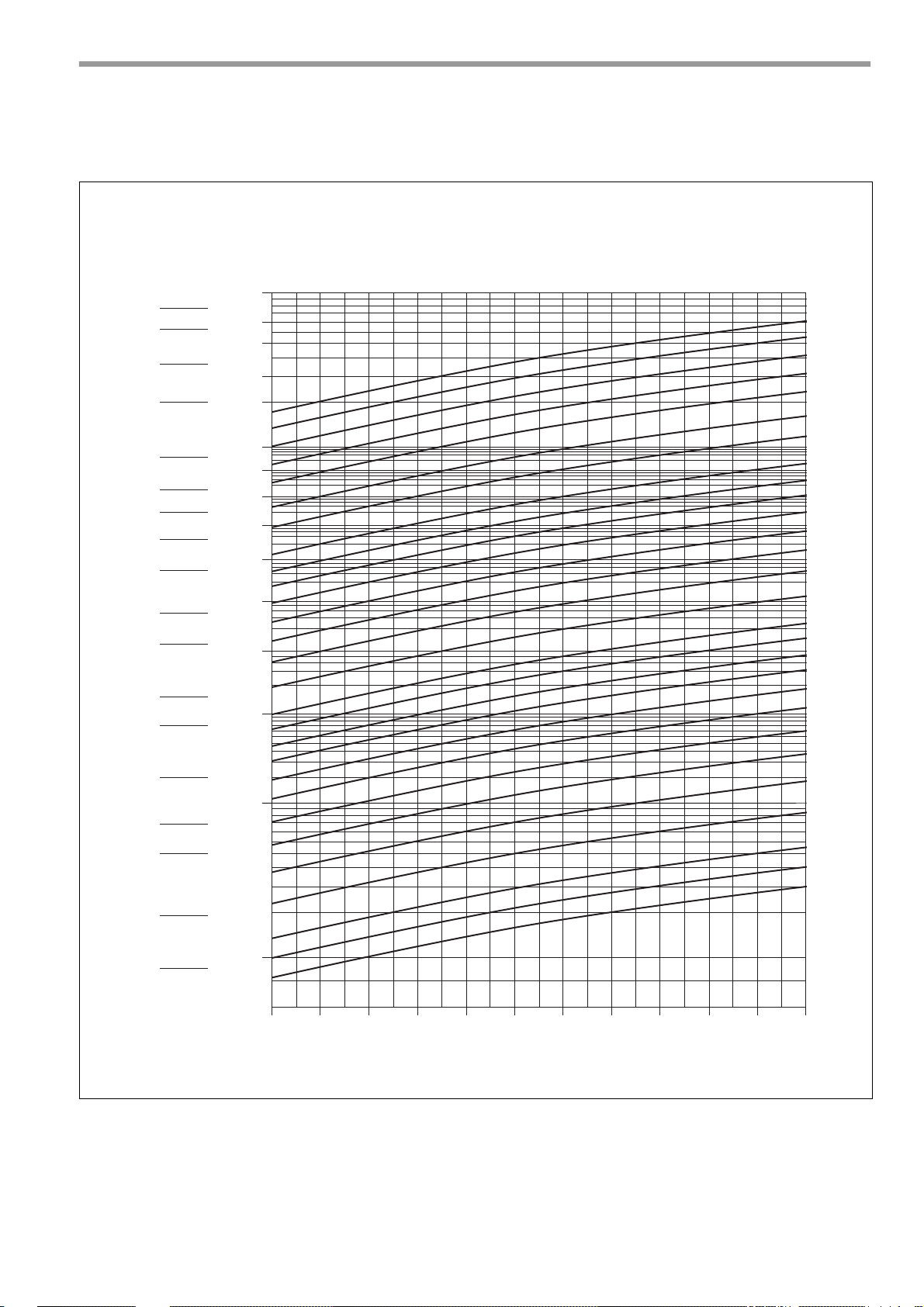
If the desired output deviates from the values specified in the tables, the nozzle size and the pump pressure
can be determined on the basis of the following diagram.
E. 30.07.07 • G. 07.06.11
23
Page 24
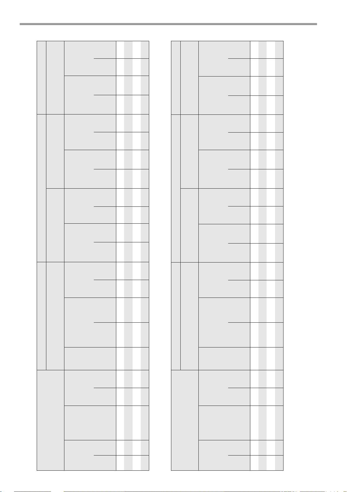
29. Adjustment tables
MDFL760 MDFL760 MDFL760
Light oil
H
i
= 11.86 [kWh/kg]
Natural gas L
H
i,n
= 9.3 [kWh/m
3
]
Natural gas H
H
i,n
= 10.4 [kWh/m
3
]
LPG
H
i,n
= 25.89 [kWh/m
3
]
Burner
output
[kW]
Boiler
output
η= 92% [kW]
Air flap
position
[ ° ]
Pump
pressure
[bar]
Oil nozzle
(Steinen)
Oil flow rate
[kg/h]
Gas nozzle
pressure
p
G
[mbar]
Gas flow rate
[m
3
/h]
Gas nozzle
pressure
p
G
[mbar]
Gas flow rate
[m
3
/h]
Gas nozzle
pressure
p
G
[mbar]
Gas flow rate
[m
3
/h]
St.
2
St.
1
St.
2
St.
2 P 9
St.
1 P 1
St.
2
St.
1
St.
2
St.
1
St.
2
St.
1
St.
2
St.
1
St.
2
St.
1
St.
2
St.
1
St.
2
St.
1
St.
2
St.
1
560 280 515 37 17.5 22 4/60°/S 4/60°/S 47.2 23,6 8.8 2.7 62,1 31.0 6.3 2.1 55.5 27.8 8.3 2.9 22.3 11.1
600 300 552 44 18 18 5/60°/SS 5/60°/SS 50.8 25.3 10.0 3.5 66.5 33.3 7.8 2.7 59.5 29.7 10,1 3.4 23,9 11.9
700 350 600 72 21 22 5/60°/SS 5/60°/SS 59.0 29.5 12.9 4.0 77,6 38.8 10,1 3.1 69,4 34,7 13.5 4.5 27,9 13.9
770 385 708 90 24 20 6/60°/SS 6/60°/SS 64,9 32.5 13.2 5.0 85,4 42,7 10.3 3.9 76.3 38.2 15.2 5.2 30,7 15.3
MDFL1070 MDFL1070 MDFL1070
Light oil
H
i
= 11.86 [kWh/kg]
Natural gas L
H
i,n
= 9.3 [kWh/m
3
]
Natural gas H
H
i,n
= 10.4 [kWh/m
3
]
LPG
H
i,n
= 25.89 [kWh/m
3
]
Burner
output
[kW]
Boiler
output
η= 92% [kW]
Air flap
position
[ ° ]
Pump
pressure
[bar]
Oil nozzle
(Steinen)
Oil flow rate
[kg/h]
Gas nozzle
pressure
p
G
[mbar]
Gas flow rate
[m
3
/h]
Gas nozzle
pressure
p
G
[mbar]
Gas flow rate
[m
3
/h]
Gas nozzle
pressure
p
G
[mbar]
Gas flow rate
[m
3
/h]
St.
2
St.
1
St.
2
St.
2 P 9
St.
1 P 1
St.
2
St.
1
St.
2
St.
1
St.
2
St.
1
St.
2
St.
1
St.
2
St.
1
St.
2
St.
1
St.
2
St.
1
St.
2
St.
1
830 450 764 43 14 20 6/60°/SS 7/60°/SS 70.0 37,9 13.0 4.0 92.0 49,9 10.2 3.1 82.3 44,6 17.5 5.6 33,1 17,9
900 450 828 52 14 20 7/60°/SS 7/60°/SS 75,9 37,9 14.0 4.8 99.8 49,9 10,9 3.8 89.2 44,6 21.2 5.6 35.8 17,9
960 480 883 57 17 18 8/60°/SS 8/60°/SS 80,9 40.5 14.5 5.0 106,4 53.2 11.3 3.9 95.2 47,6 25,9 6.5 38.2 19,1
1070 540 984 85 26 22 8/60°/SS 8/60°/SS 90.2 45.5 16.5 7,6 118,6 59,9 12.9 5.9 106,1 53.5 29.9 7.8 42,6 21.5
24
E. 30.07.07 • G. 07.06.11
Page 25
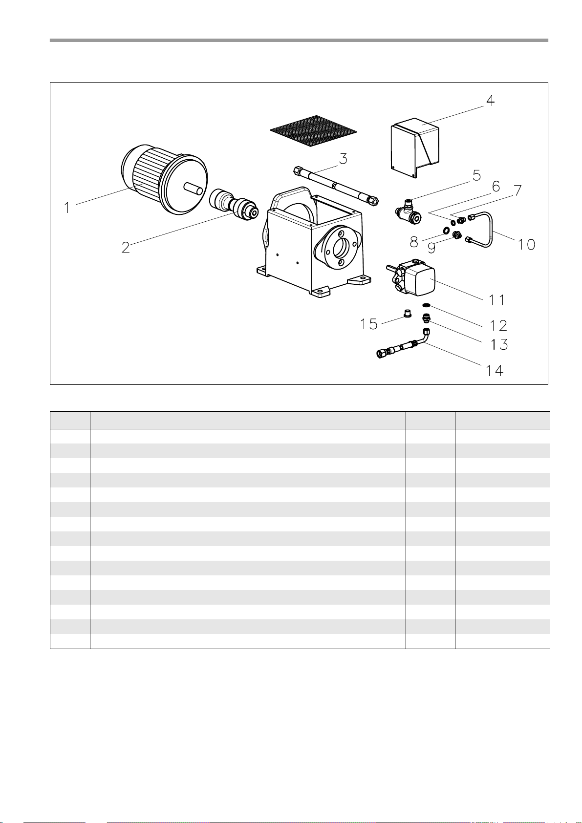
30. Exploded views / spare parts lists
ZBZ_2-237
Oil pump unit MDFL
Item Designation PU Art. No.
1 Motor 1.1 kW 50 Hz 1 36-90-11538
2 Coupling compl. for pump unit MK 1 47-90-27103
3 Hydraulic hose DN 8, 1500 mm lg. 1 47-90-25302
4 Pressure switch compl. with cable 1 47-90-25363
5 T-piece compl. for pump unit 1 44-90-23080
6 Conical nipple AL 14 x 10 x 2 50 37-50-10788
7 Pressure pipe nipple 5 47-50-20127
8 Conical nipple AL 13 x 18 x 2 50 37-50-11293
9 Hose nipple R 1/4“ 10 47-50-20862
10 Pressure pipe compl. for pump unit MDFL 1 47-90-27104
11 Oil pump AJ4, compl. for pump unit MDFL 1 47-90-27109
12 Sealing washer AL 13 x 18 x 2 50 37-50-11293
13 Hose nipple NW6 R 1/4“ 10 37-50-11348
14 Metal hose NW6 1200 mm lg. 1 47-90-11347
15 Screwed sealing plug R 1/4“ with hexagon socket 5 37-50-11798
E. 30.07.07 • G. 07.06.11
25
Page 26
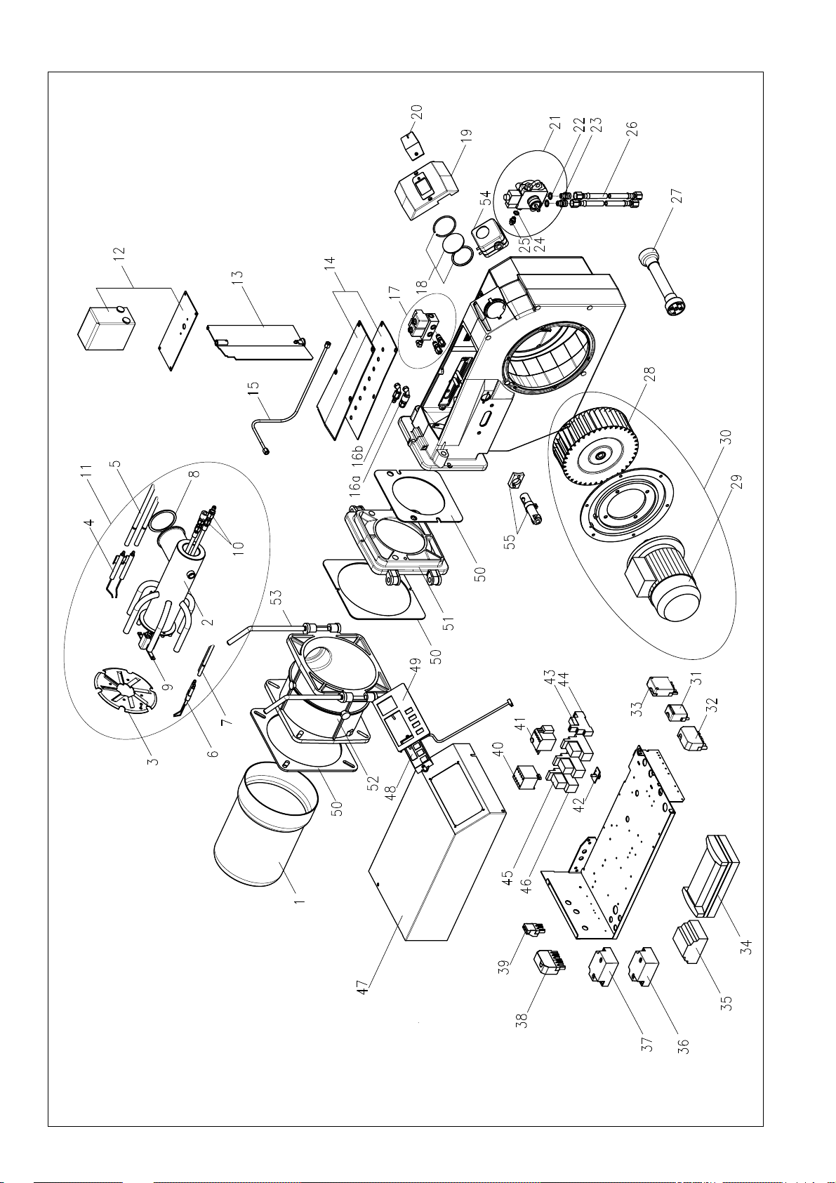
Combined gas/oil burner MDFL760
ZBZ_2-202.1
E. 30.07.07 • G. 07.06.11
26
Page 27
Item Designation PU Art. No.
1 Burner pipe MDFL760 1 47-90-25517
1 Burner pipe MDFL760, extended 100 mm 1 47-90-25514
1 Burner pipe MDFL760, extended 200 mm 1 47-90-26419
2 Mixing head MDFL welded 1 47-90-27084
2 Mixing head MDFL welded, extended 100 mm 1 47-90-27085
2 Mixing head MDFL welded, extended 200 mm 1 47-90-27086
3 Baffle plate MDFL 1 47-90-25515
4 Oil ignition electrodes compl. 1 47-90-26213
5 Oil ignition cable set 2 47-50-26104
5 Oil ignition cable set, extended 100 mm 2 47-50-25134
5 Oil ignition cable set, extended 200 mm 2 47-50-25005
6 Gas ignition electrode compl. 1 47-90-24921
7 Gas ignition cable set 2 47-50-25134
7 Gas ignition cable set, extended 100 mm 2 47-50-25004
7 Gas ignition cable set, extended 200 mm 2 47-50-25005
8 Seal for mixing head MDFL 5 47-50-25521
9 Nozzle holder MDFL compl. pre-assembled 1 47-90-25548
9 Nozzle holder MDFL compl. pre-assembled, extended 100 mm 1 47-90-25561
9 Nozzle holder MDFL compl. pre-assembled, extended 200 mm 1 47-90-26240
10 Hydraulic set 1 47-90-27087
11 Mixing head MDFL compl. pre-assembled, excl. ignition cable 1 47-90-25473
11 Mixing head MDFL compl. pre-assembled, extended 100 mm,
1 47-90-25562
excl. ignition cable
11 Mixing head MDFL compl. pre-assembled, extended 200 mm,
1 47-90-26108
excl. ignition cable
12 Actuator drive SAD 1.5 for MG20-ZM 1 47-90-24763
13 Air damper MG20 to 12.08 1 47-90-24663
13 Air damper MG20 from 12.08 1 47-90-27030
14 Cover for MG20 with seals 1 47-90-10698
15 Pressure pipe MDFL760 compl. 1 47-90-25560
16a Hydraulic sealing nipple T2320V, compl. 1 47-90-25465
16b Hydraulic coupling compl. 1 47-90-25464
17 Double solenoid valve block compl. 1 47-90-27105
18 Sight glass with seal 1 36-90-11544
19 Cover MG20 1 47-90-24857
20 Cover for sight glass 5 47-50-12106
21 Oil pump AL95, compl. for MDFL760 1 47-90-27125
22 Conical nipple AL 13 x 18 x 2 50 37-50-11293
23 Hose nipple R 1/4“ x R 3/8“ 10 46-50-10554
24 Sealing washer AL 14 x 10 x 2 50 37-50-10788
25 Pressure pipe nipple GES 6LLR 5 47-50-20127
26 Metal hose NW8 1500 mm lg. 1 57-90-10348
27 Coupling compl. 1 36-90-11539
28 Fan wheel Ø 218 x 80 1 36-90-11540-01
29 1.1 kW 400 V / 50 Hz motor 1 47-90-26721
30 1.1 kW motor with fan wheel 1 47-90-25205
31 4-pin socket green 1 37-90-20744
32 7-pin socket black/brown 1 37-90-20731
33 5-pin socket black 1 37-90-20748
E. 30.07.07 • G. 07.06.11
27
Page 28
Item Designation PU Art. No.
34 Logic module CL-LSR 1 47-90-25177
35 Control box MPA 22 1 47-90-24166
36 Ignition transformer Fida Mod. 26/35 incl. ignition cable 460 mm lg. 1 47-90-24469
37 Ignition transformer Fida Mod. 26/48 incl. ignition cable 460 mm lg. 1 47-90-26930
38 7-pin socket green 1 37-90-10831
39 3-pin socket black 1 37-90-20739
40 Miniature motor contactor B7-30-10 1 47-90-25171
41 Thermal overload relay 2.4 - 4 A 1 47-90-25172
42 Remote-manual switch 1 47-90-25040
43 Relay CR-P230AC2 1 47-90-25199
44 Base CR-PLSx 1 47-90-26713
45 Relay CR-M230AC4 1 47-90-25181
46 Base CR-M4LS 1 47-90-26731
- Mini motor contactor B7-30-10 for pump unit 1 47-90-25171
- Thermal overload relay for pump unit 2.4 - 4 A 1 47-90-25172
47 Hood for switch box MK30 1 47-90-25206
48 MPA display AM07 1 47-90-24167
49 Facing panel MDFL1070 1 47-90-25074
50 Seal set 1 47-90-26722
51 Gas jacket MG20 part 2 1 44-90-30242
52 Gas jacket MG20 part 1 1 44-90-33245
53 Securing rod MG20 2 46-50-21085
54 Differential pressure monitor 2.5 - 50 mbar 1 47-90-26723
55 Flame controller KLC1000 1 47-90-27184
- Inlet nozzle 1 36-90-11541
28
E. 30.07.07 • G. 07.06.11
Page 29
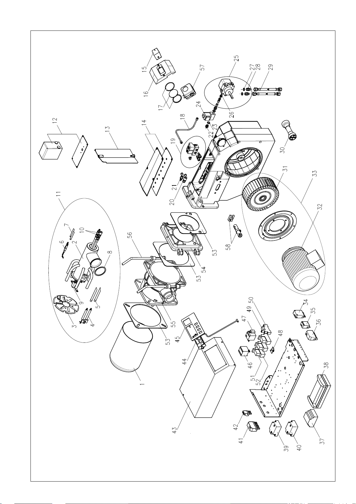
Combined gas/oil burner MDFL1070
ZBZ_2-240.1
E. 30.07.07 • G. 07.06.11
29
Page 30
Item Designation PU Art. No.
1 Burner pipe MDFL1070 1 47-90-25472
1 Burner pipe MDFL1070, extended 100 mm 1 47-90-26420
1 Burner pipe MDFL1070, extended 200 mm 1 47-90-26421
2 Mixing head MDFL welded 1 47-90-27084
2 Mixing head MDFL welded, extended 100 mm 1 47-90-27085
2 Mixing head MDFL welded, extended 200 mm 1 47-90-27086
3 Baffle plate MDFL 1 47-90-25515
4 Oil ignition electrodes compl. 1 47-90-26213
5 Oil ignition cable set 2 47-50-26104
5 Oil ignition cable set, extended 100 mm 2 47-50-25134
5 Oil ignition cable set, extended 200 mm 2 47-50-25005
6 Gas ignition electrode compl. 1 47-90-24921
7 Gas ignition cable set 2 47-50-25134
7 Gas ignition cable set, extended 100 mm 2 47-50-25004
7 Gas ignition cable set, extended 200 mm 2 47-50-25005
8 Seal for mixing head MDFL 5 47-50-25521
9 Nozzle holder MDFL compl. pre-assembled 1 47-90-25548
9 Nozzle holder MDFL compl. pre-assembled, extended 100 mm 1 47-90-25561
9 Nozzle holder MDFL compl. pre-assembled, extended 200 mm 1 47-90-26240
10 Hydraulic set 1 47-90-27087
11 Mixing head MDFL compl. pre-assembled, excl. ignition cable 1 47-90-25473
11 Mixing head MDFL compl. pre-assembled, extended 100 mm,
1 47-90-25562
excl. ignition cable
11 Mixing head MDFL compl. pre-assembled, extended 200 mm,
1 47-90-26108
excl. ignition cable
12 Actuator drive SAD 1.5 for MG20-ZM 1 47-90-24763
13 Air damper MG20 to 12.08 1 47-90-24663
13 Air damper MG20 from 12.08 1 47-90-27030
14 Cover for MG20 with seals 1 47-90-10698
15 Cover for sight glass 5 47-50-12106
16 Cover MG20 1 47-90-24857
17 Sight glass with seal 1 36-90-11544
18 Pressure pipe MDFL1070 compl. 1 47-90-25468
19 Double solenoid valve block compl. 1 47-90-27105
20 Hydraulic coupling compl. 1 47-90-25464
21 Hydraulic sealing nipple T2320V, compl. 1 47-90-25465
22 Hose nipple R 1/4“ x6LL 1 47-90-20862
23 Conical nipple AL 13 x 18 x 2 50 37-50-11293
24 Solenoid valve R 1/4“ compl. for MDFL burner 1 47-90-27106
25 Oil pump AJ4 compl. for MDFL burner 1 47-90-26063
26 Pressure pipe nipple GES 6LLR x 1/8“ 5 47-50-20127
27 Conical nipple AL 14 x 10 x 2 50 37-50-10788
28 Hose nipple R 1/4“ x R 3/8“ 10 46-50-10554
29 Metal hose NW8 1500 mm lg. 1 57-90-10348
30 Coupling MDFL1070 compl. 1 47-90-27179
31 Fan wheel Ø 224 x 82 1 47-90-24847
32 2.2 kW 400 V / 50 Hz motor 1 47-90-24846
33 2.2 kW motor with fan wheel 1 47-90-25508
34 5-pin socket black 1 37-90-20748
30
E. 30.07.07 • G. 07.06.11
Page 31

Item Designation PU Art. No.
35 4-pin socket green 1 37-90-20744
36 7-pin socket black/brown 1 37-90-20731
37 Logic module CL-LSR 1 47-90-25177
38 Control box MPA 22 1 47-90-24166
39 Ignition transformer Fida Mod. 26/35 incl. ignition cable 460 mm lg. 1 47-90-24469
40 Ignition transformer Fida Mod. 26/48 incl. ignition cable 460 mm lg. 1 47-90-26930
41 7-pin socket green 1 37-90-10831
42 3-pin socket black 1 37-90-20739
43 Hood for switch box MK30 1 47-90-25206
44 MPA display AM07 1 47-90-24167
45 Facing panel MDFL 1 47-90-25074
46 Miniature motor contactor B7-30-10 1 47-90-25171
47 Thermal overload relay 4 - 6 A 1 47-90-25173
48 Remote-manual switch 1 47-90-25040
49 Relay CR-P230AC2 1 47-90-25199
50 Base CR-PLSx 1 47-90-26713
51 Relay CR-M230AC4 1 47-90-25181
52 Base CR-M4LS 1 47-90-26731
- Mini motor contactor B7-30-10 for pump unit 1 47-90-25171
- Thermal overload relay for pump unit 2.4 - 4 A 1 47-90-25172
53 Seal set 1 47-90-26722
54 Gas jacket MG20 part 2 1 44-90-30242
55 Gas jacket MG20 part 1 1 44-90-33245
56 Securing rod MG20 2 46-50-21085
57 Differential pressure monitor 2.5 - 50 mbar 1 47-90-26723
58 Flame controller KLC1000 1 47-90-27184
- Inlet nozzle 1 36-90-11541
E. 30.07.07 • G. 07.06.11
31
Page 32
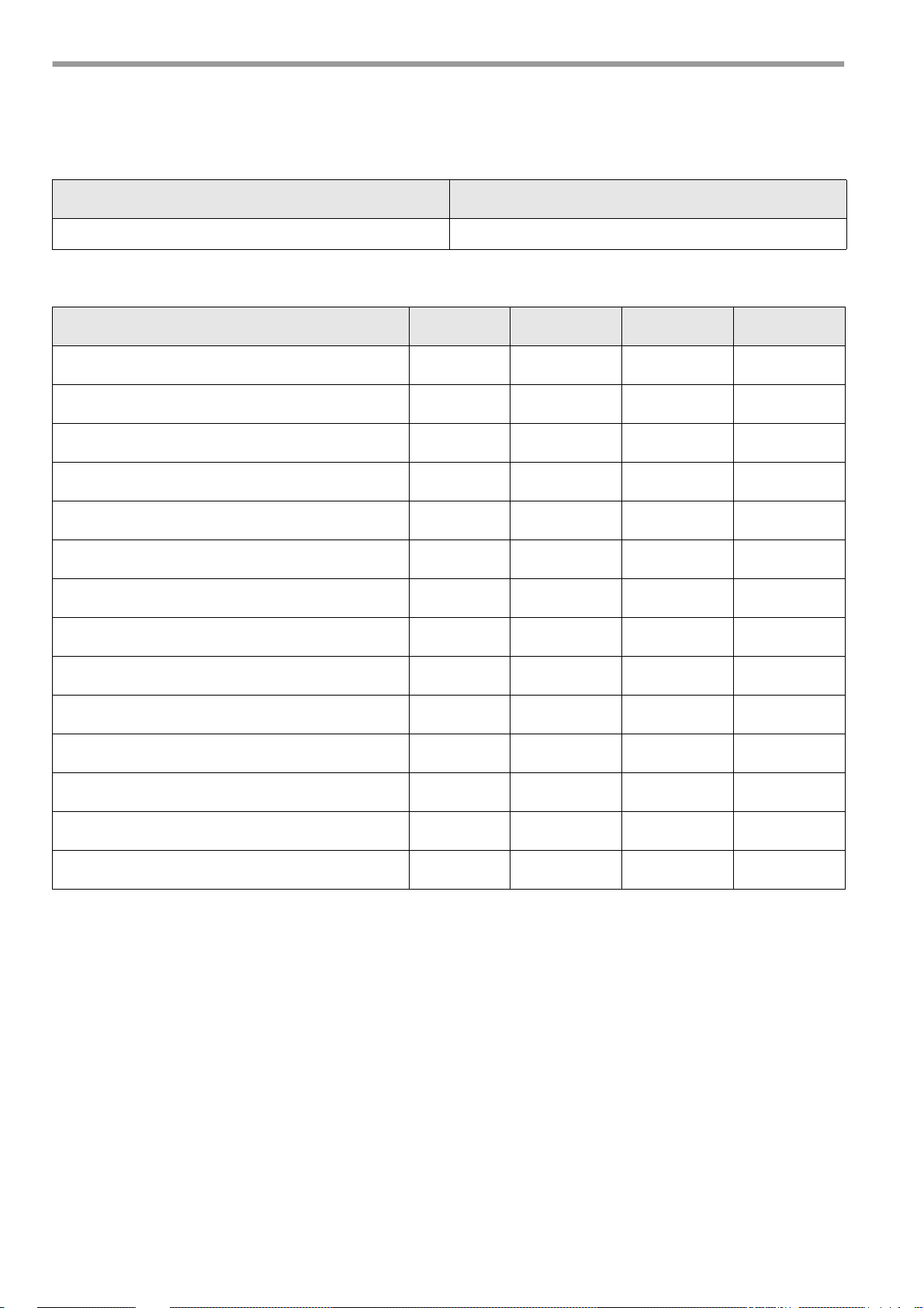
31. Adjustments log
Please enter the measured values into the Adjustments log.
Boiler type Gas fitting
Measured values min. max. Date
P0 (start point)
P1 (min load)
P9 (max load)
Flue gas temperature °C
Carbon dioxide (CO2 level) %
O2 content %
CO level %
Flue mbar
Nozzle pressure mbar
Boiler pressure mbar
Room temperature °C
Gas type
Setting value V at the fitting
Setting value N at the fitting
32
E. 30.07.07 • G. 07.06.11
Page 33
32. Declaration of conformity for dual-fuel burner for heating oil EL and
natural gas or liquid gas
We, Enertech GmbH, D-58675 Hemer, hereby declare on its own responsibility that the products
MDFL. ...
are in conformity with the following standards and regulations:
EN 267
EN 676
EN 50081
EN 50082
EN 60335
These products are CE labelled in compliance with the provisions of the following directives:
98 / 37 / EEC Machinery Directive
89 / 336 / EEC EMC Directive
73 / 23 / EEC Low Voltage Directive
92 / 42 / EEC Energy Efficiency Directive
CE - 0085BR0306 according to Test Report 143192E1/15563 (GWI) and
CE - 0085BR0307 according to Test Report 139082E1/15564 (GWI).
Hemer, 1 November 2007
R. Rebbe, Head of Operation
E. 30.07.07 • G. 07.06.11
33
Page 34
Page 35

Enertech Limited,
P O Box 1,
Vines Lane
Droitwich,
Worcestershire,
WR9 8NA
 Loading...