

Page 1
USER MANUAL
HIGH INTERCEPT LOW NOISE
AMPLIFIER (HILNA
TM
)
MODEL NUMBER: HILNA GPS
6002-1300-1201
Trusted RF Solutions
NUWAVES ENGINEERING
132 EDISON DRIVE.
MIDDLETOWN, OHIO 45044
PH: 513-360-0800
FAX: 513-539-8782
www.nuwaves.com
Page 2

HILNA GPS User Manual
Document 6002-1300-1201 Rev – 08222014
1
1 HILNA
TM
PRODUCT LINE OVERVIEW
NuWaves’ HILNA family of low noise amplifiers (LNAs) is designed to achieve high RF gain while
maintaining extremely low noise, and high third-order intercept point across a wide band. The HILNA’s
robust power supply also operates over a very broad range easily allowing the unit to be integrated into
systems without regard to power supply precision.
1.1 HILNA
TM
PRODUCT LINE HIGHLIGHTS
High Performance - Noise, Gain, Intercept, Dynamic Range: Unique combination of extremely
low noise, high gain, high output intercept, and wide band frequency coverage.
Robust Power Supply: Operates over a very broad range of power supply voltages. Included with
each LNA is a power connector with cable, as required.
Enclosures:
o The HILNA V1, HILNA G2V1, HILNA HF, and HILNA CF are housed in a black-anodized
extruded aluminum enclosure with optional mounting flanges.
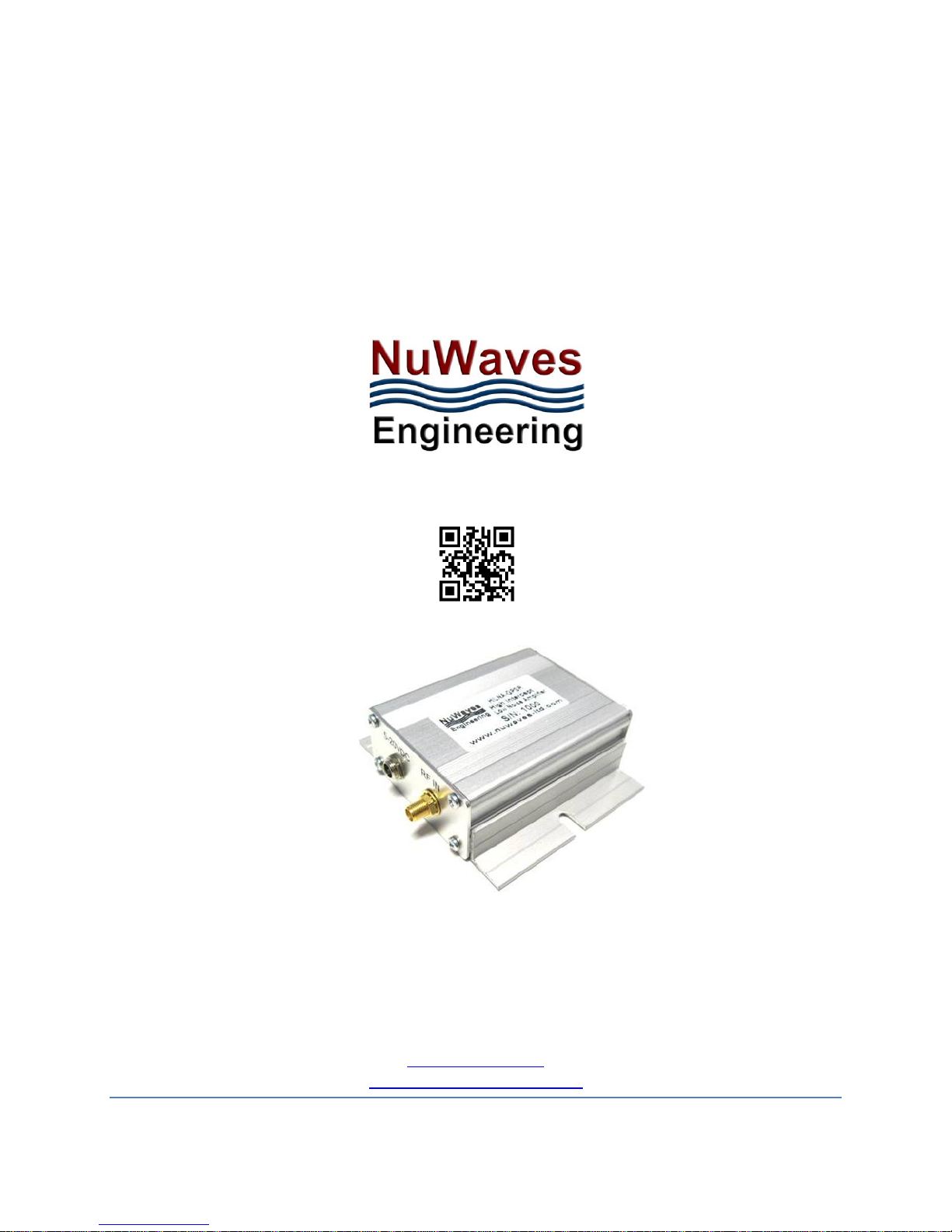
o The HILNA GPS is housed in a silver-anodized extruded aluminum enclosure with
optional mounting flanges.
o The µHILNA is housed in a miniature sleek black anodized milled aluminum
enclosure with mounting holes incorporated into the chassis.
o The HILNA 3G is housed in a black anodized milled aluminum enclosure with
mounting holes incorporated into the chassis.
o The HILNA CX is housed in a nickel plated rugged aluminum enclosure with
mounting holes incorporated into the chassis.
Completely Characterized: The HILNA family of low noise amplifiers has been completely
characterized over temperature, voltage, and frequency. The amplifiers are robust, offering
significant value for the OEM user or the Systems Integrator.
User Friendly: Reverse-voltage protection and regulator thermal shutdown provide defenses
against user interface issues.
High Reliability: NuWaves’ selection of conservatively rated components provides high
reliability. Each HILNA is inspected to IPC-A-610 Class II quality standards.
ESD Protection: The HILNA Amplifiers are suitable for many types of applications where ESD
susceptibility is prominent. The amplifiers are designed to withstand up to 1000 V utilizing ESD
waveforms described in IEC 61000 4-2.
Applications: IF or RF Buffer Amplifier ▪ Military Radios ▪ RF Wideband Front-Ends ▪ RF Pre-Amp ▪
TV ▪ Final Stage Amplifier for Low-Level Repeaters ▪ Ultra Low Noise Applications ▪ LNA for
Cellular Base Station ▪ High Linearity Systems ▪ High-Performance Receivers ▪ High-Power Drive
Signals for Increased Dynamic Range ▪ High Reliability RF Amplifier Applications ▪ Base Station
Applications ▪ VHF/UHF Amplification ▪ Final PA for Low-Power Applications ▪ Low-Noise
Transmit Driver ▪ Cable Modem ▪ Fixed Wireless ▪ Mobile Infrastructure ▪
Industrial/Scientific/Medical Band Applications
1.2 HILNA
TM
PRODUCT LINE MODELS
NuWaves offers several variants of the HILNA line-up. Product availability is depicted in Table 1.
Page 3
HILNA GPS User Manual
Document 6002-1300-1201 Rev – 08222014
2
Table 1: List of Models
MODEL
DESCRIPTION
HILNA V1
50 MHz to 1 GHz,
20 dB Gain
µHILNA
50 MHz to 1500 MHz,
20 dB Gain
HILNA G2V1
50 MHz to 1 GHz,
40 dB Gain
HILNA GPS
1.2 GHz to 1.6 GHz,
32 dB Gain
HILNA CF
50 MHz to 1 GHz,
38 dB Gain
HILNA HF
2 MHz to 50 MHz,
30 dB Gain
HILNA 3G
1 GHz to 3 GHz,
50 dB Gain
HILNA CX
5 GHz to 10 GHz,
30 dB to 43 dB Gain
2 HILNA
TM
GPS OVERVIEW
NuWaves’ HILNA GPS is a broadband low noise amplifier designed to achieve high gain while
maintaining low noise and a high third order intercept point specifically for L1 (1575.43 MHz) and L2
(1227.6 MHz) GPS signals.
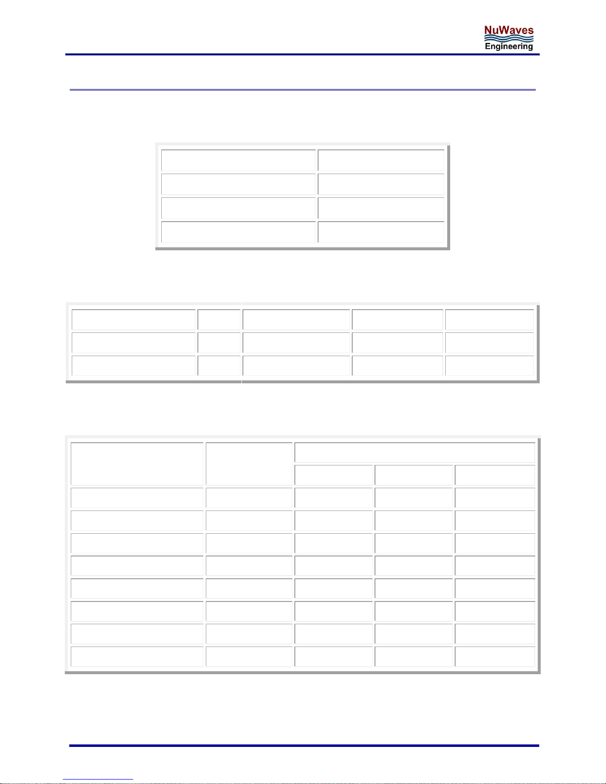
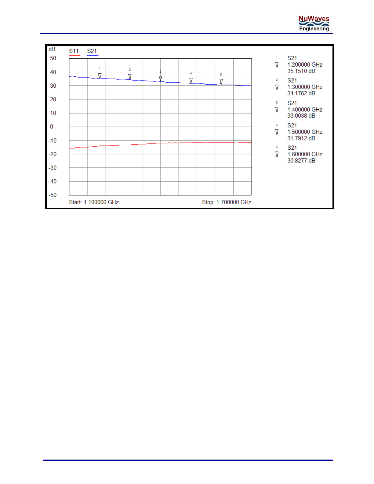
This high-performance module delivers 32 dB of gain across the frequency range of 1200 MHz to 1600
MHz with an OIP3 of +30 dBm and less than 1 dB of noise figure. The HILNA GPS is also usable up to
2000 MHz with over 28 dB of gain.
HILNA GPS’s robust power supply also operates over a very broad range easily allowing the unit to be
integrated into systems without regard to power supply precision.
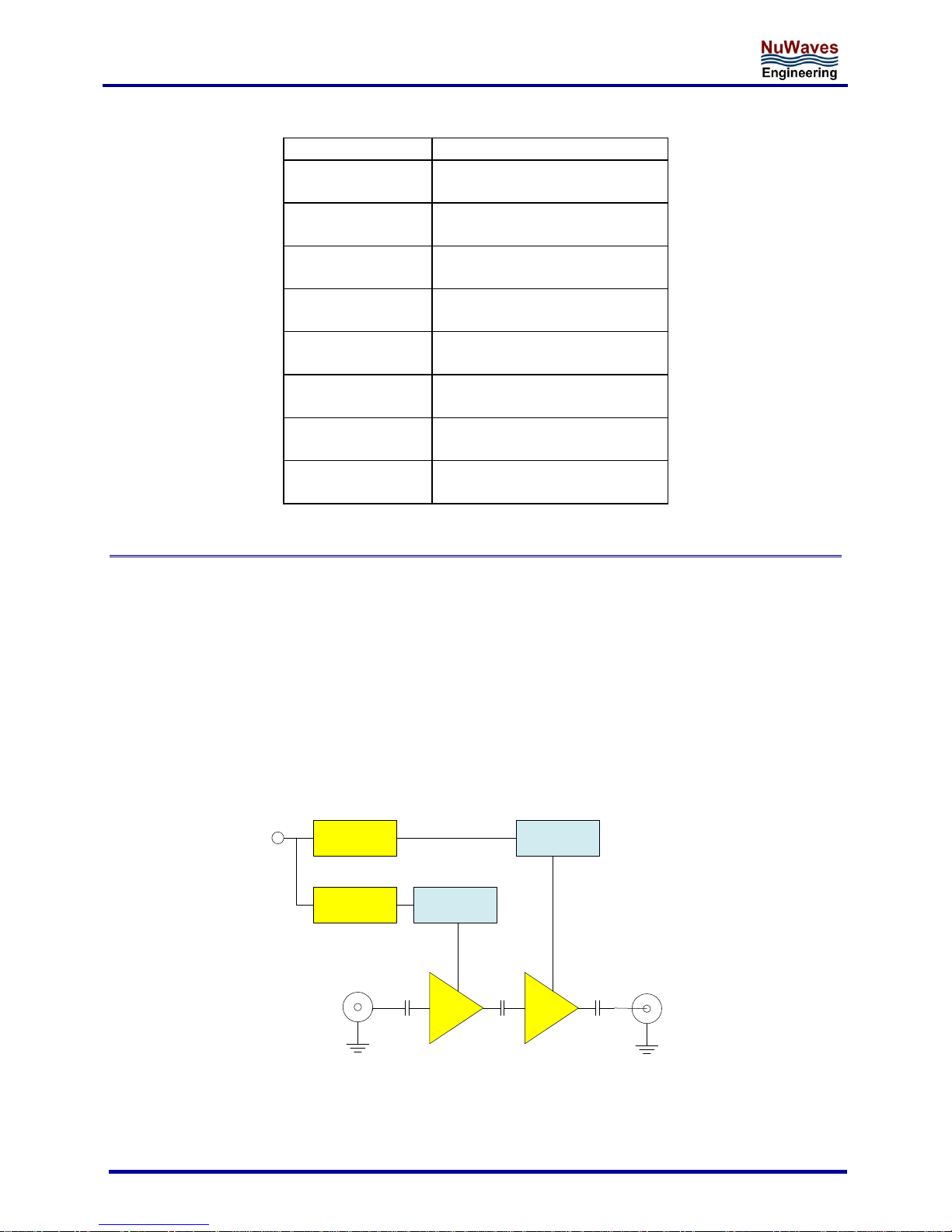
Linear
Regulator
Active Bias
1.2 GHz-1.6 GHz
(HILNAGPS)
G=18 dB
5-20 VDC
G=18 dB
Linear
Regulator
Active Bias
Figure 1: HILNA GPS Functional Diagram
Page 4
HILNA GPS User Manual
Document 6002-1300-1201 Rev – 08222014
3
2.1 HILNA GPS ELECTRICAL DATA
Table 2: HILNA GPS Absolute Maximum Rating
Operating Voltage
+20 VDC
RF Pin
+15 dBm
Operating Temperature
-30 to + 70 0C
Storage Temperature
-40 to + 85 0C
Table 3: HILNA GPS DC Specifications
Min
Typ
Max
Operating Voltage
V
+5
+12
+20
Current Consumption
mA
130
140
150
Table 4: HILNA GPS RF Specifications
PARAMETER
UNIT
HILNA GPS
Min
Typ
Max
Frequency Range
MHz
1200
1600
Gain
dB
30
33
35
Noise Figure
dB
0.7
.8
1.6
OIP3
dBm
28
30
32
P1dB
dBm
16
18
19
VSWR In
1.5:1
VSWR Out
2.0:1
Reverse Isolation
dB
45
53
56
Page 5
HILNA GPS User Manual
Document 6002-1300-1201 Rev – 08222014
4
Figure 2: HILNA GPS Frequency Response
Page 6
HILNA GPS User Manual
Document 6002-1300-1201 Rev – 08222014
5
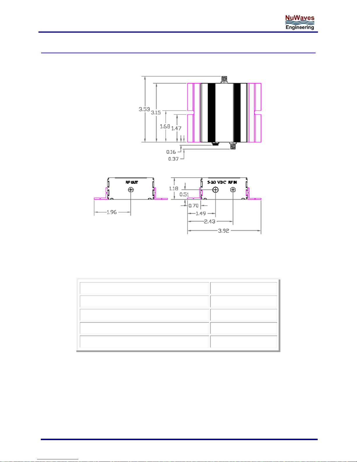
2.2 HILNA GPS MECHANICAL SPECIFICATIONS
Figure 3: HILNA GPS Mechanical Outline
Table 3: HILNA GPS Mechanical Specifications
RF Bulkhead Connector
SMA female
RF Input and Output Mating Connector
SMA male
DC Power Connector
Type 2 mm Circular
Dimensions (L x W x H)
3.15” x 2.50” x 1.18”
Weight
5.00 oz.
Page 7

HILNA GPS User Manual
Document 6002-1300-1201 Rev – 08222014
6
3 INSTALLING, CONNECTING, AND USING THE HILNA AMPLIFIER
HILNA amplifiers have been designed to be highly reliable under the specified operating conditions. The
following installation and interfacing guidelines should be followed to prevent damage to the RF
module.
3.1 CABLING
The HILNA GPS is equipped with high-performance RF connectors. Gold plated SMA-type receptacles are
used because they perform very well across the usable frequency range of the unit. For optimal
performance, a high-quality 50 coaxial cable with SMA-type plugs should be used to interface with the
amplifier.
Caution: Due to the wideband nature of the unit, installation should not be attempted on a tower
with transmit antennas.
If cables with the SMA-type connectors are not available, high quality adaptors are available for most
coaxial connector types.
3.2 POWER SUPPLY
The HILNA GPS contains internal linear voltage regulators. These regulators protect the circuitry from
voltage variations at the input and allow for the wide operating voltage. The power connector for the
units is an industry standard 2 mm circular connector. The only restrictions on the power source for the
unit are:
- Capable of sourcing 80 mA of current
- Capable of sourcing +5 VDC to +20 VDC
Car batteries (through a cigarette lighter adaptor), laboratory DC power supplies, or wall transformers
are suitable power sources as long as the superimposed ripple is low in amplitude.
3.3 CONNECTIONS
Caution: Do not apply RF to the unit until after all cable connections are made and power has been
applied.
Making the connections from the HILNA GPS is easily accomplished:
1. Connect the "RF OUT" connector on the unit to a 50 coaxial cable
2. Apply power to the unit by first plugging in the power cable sent with the unit into the DC power
input.
3. Connect the red lead to the positive side of the power supply and connect the black lead to the
negative side of the power supply. Power is now ready to be applied to the unit.
4. Connect the RF Source to the RF Destination with a second 50 coaxial cable.
5. Apply RF to the input cable assembly.
Caution: The HILNA amplifier contains components that are sensitive to
Electro-Static Discharge (ESD). The use of wrist strap, mats, and ground
straps should be adhered to during the installation process.
Page 8

HILNA GPS User Manual
Document 6002-1300-1201 Rev – 08222014
7
Powering down the unit is done by reversing this procedure.
Connection Summary:
Connect the RF Output to a good load. The characteristic impedance is 50 Ω.
Apply DC (+12 VDC Typical) at the power connector.
Connect an RF source to the RF Input connector.
Caution: Excess drive levels at the input to the amplifier can permanently damage
the unit. Under no circumstance should the RF Input level exceed +20 dBm.
3.4 ENVIRONMENTAL SPECIFICATIONS
The HILNA GPS units are rated for operation from -20 to +70 °C. The enclosure is NOT watertight so the
unit must be kept dry. It is recommended that the unit be installed in a well-ventilated area or mounted
to a heat sink if the input voltage exceeds +12 VDC. The unit will run warmer as the input voltage
increases.
4 GETTING HELP - APPLICATIONS ENGINEERING
NuWaves Engineering offers technical support for basic configuration help and troubleshooting, Monday
through Friday, 8 a.m. to 5 p.m. Eastern Time.
Technical Assistance, Application Engineering, and Sales:
Phone: (513) 360-0800
Email: [email protected]
NuWaves Home Page: http://www.nuwaves.com
Product Warranty:
http://www.nuwaves.com/wp-content/uploads/2011/04/NuWaves_Warranty__Repair.pdf
4.1 GENERAL INFORMATION
Copyright © 2006 - 2014 NuWaves Ltd. All rights reserved. The information contained in this user
manual is copyright protected. NuWaves reserves the right to make periodic modifications and product
improvements to the HILNA product line and the associated documentation.
 Loading...