

Page 1

NuMaker-M032SE
Feb. 20, 2019 Page 1 of 37 Rev 1.00
NUMAKER-M032SE USER MANUAL
Maker Nu-mbed NUC472 User Manual
ARM® Cortex®-M
32-bit Microcontroller
NuMaker-M032SE
User Manual
NuMicro® M032 Series
The information described in this document is the exclusive intellectual property of
Nuvoton Technology Corporation and shall not be reproduced without permission from Nuvoton.
Nuvoton is providing this document only for reference purposes of NuMicro microcontroller based system
design. Nuvoton assumes no responsibility for errors or omissions.
All data and specifications are subject to change without notice.
For additional information or questions, please contact: Nuvoton Technology Corporation.
www.nuvoton.com
Page 2

NuMaker-M032SE
Feb. 20, 2019 Page 2 of 37 Rev 1.00
NUMAKER-M032SE USER MANUAL
Maker Nu-mbed NUC472 User Manual
Table of Contents
1 Overview ............................................................................................. 6
NuMaker-M032SE Features ......................................................................... 6 1.1
2 NuMaker-M032SE Overview ..................................................................... 8
Front View ............................................................................................... 8 2.1
Rear View ............................................................................................... 9 2.2
Arduino UNO Compatible Extension Connectors ................................................ 10 2.3
Pin Assignment for Extension Connectors ........................................................ 12
2.4
System Configuration ................................................................................ 15 2.5
2.5.1 VIN Power Source ............................................................................................ 15
2.5.2 5 V Power Sources ........................................................................................... 15
2.5.3 3.3 V Power Sources ......................................................................................... 15
2.5.4 1.8V Power Sources ......................................................................................... 16
2.5.5 Power Connectors ............................................................................................ 16
2.5.6 USB Connectors .............................................................................................. 16
2.5.7 Power Switches ............................................................................................... 16
2.5.8 Power Supply Models ........................................................................................ 17
2.5.9 External Reference Voltage Connector ................................................................... 20
2.5.10 Ammeter Connector .......................................................................................... 20
2.5.11 Extension Connectors ........................................................................................ 20
2.5.12 Push-Buttons .................................................................................................. 21
2.5.13 LEDs ............................................................................................................ 21
Nu-Link2-Me ........................................................................................... 21 2.6
PCB Placement ....................................................................................... 22 2.7
3 Quick Start ........................................................................................ 23
Toolchains Supporting ............................................................................... 23 3.1
Nuvoton Nu-Link Driver Installation ................................................................ 23 3.2
BSP Firmware Download ............................................................................ 25 3.3
Hardware Setup ....................................................................................... 25 3.4
Find the Example Project ............................................................................ 27 3.5
Execute the Project under Toolchains ............................................................. 27 3.6
3.6.1 Keil MDK ....................................................................................................... 27
3.6.2 IAR EWARM ................................................................................................... 31
3.6.3 NuEclipse ...................................................................................................... 32
Page 3

NuMaker-M032SE
Feb. 20, 2019 Page 3 of 37 Rev 1.00
NUMAKER-M032SE USER MANUAL
Maker Nu-mbed NUC472 User Manual
4 NuMaker-M032SE Schematics ................................................................ 33
Nu-Link2-Me ........................................................................................... 33 4.1
M032 platform ......................................................................................... 34 4.2
Extension Connector ................................................................................. 35 4.3
5 REVISION HISTORY ............................................................................ 36
Page 4

NuMaker-M032SE
Feb. 20, 2019 Page 4 of 37 Rev 1.00
NUMAKER-M032SE USER MANUAL
Maker Nu-mbed NUC472 User Manual
List of Figures
Figure 1-1 NuMaker-M032SE Board ............................................................................................... 6
Figure 2-1 Front View of NuMaker-M032SE .................................................................................... 8
Figure 2-2 Rear View of NuMaker-M032SE .................................................................................... 9
Figure 2-3 Arduino UNO Compatible Extension Connectors ......................................................... 10
Figure 2-4 M032SE3AE Extension Connectors ............................................................................. 12
Figure 2-5 External Power Supply Sources on Nu-Link2-Me ........................................................ 17
Figure 2-6 External Power Supply Sources on M032 platform ...................................................... 18
Figure 2-7 Separate the Nu-Link2-Me from NuMaker-M032SE .................................................... 19
Figure 2-8 Wiring between Ammeter Connector and Ammeter ..................................................... 20
Figure 2-9 Front Placement ........................................................................................................... 22
Figure 2-10 Rear Placement .......................................................................................................... 22
Figure 3-1 Nu-Link USB Driver Installation Setup .......................................................................... 23
Figure 3-2 Nu-Link USB Driver Installation .................................................................................... 24
Figure 3-3 Open VCOM Function .................................................................................................. 25
Figure 3-4 ICE USB Connector ...................................................................................................... 25
Figure 3-5 Device Manger .............................................................................................................. 26
Figure 3-6 PuTTY Session Setting................................................................................................. 26
Figure 3-7 Template Project Folder Path ....................................................................................... 27
Figure 3-8 Warning Message of “Device not found” ...................................................................... 27
Figure 3-9 Project File Migrate to Version 5 Format ...................................................................... 28
Figure 3-10 Debugger Setting in Options Window......................................................................... 28
Figure 3-11 Programming Setting in Options Window ................................................................... 29
Figure 3-12 Compile and Download the Project ............................................................................ 29
Figure 3-13 Keil MDK Debug Mode ............................................................................................... 30
Figure 3-14 Debug Message on Serial Port Terminal Windows .................................................... 30
Figure 3-15 IAR EWARM Window ................................................................................................. 31
Figure 3-16 Compile and Download the Project ............................................................................ 31
Figure 3-17 IAR EWARM Debug Mode ......................................................................................... 32
Figure 3-18 Debug Message on Serial Port Terminal Windows .................................................... 32
Figure 4-1 Nu-Link2-Me Circuit ...................................................................................................... 33
Figure 4-2 M032 platform Circuit.................................................................................................... 34
Figure 4-3 Extension Connectors Circuit ....................................................................................... 35
Page 5

NuMaker-M032SE
Feb. 20, 2019 Page 5 of 37 Rev 1.00
NUMAKER-M032SE USER MANUAL
Maker Nu-mbed NUC472 User Manual
List of Tables
Table 2-1 Arduino UNO Extension Connectors and M032SE3AE Mapping GPIO List ................. 11
Table 2-2 M032SE3AE Full-pin Extension Connectors and GPIO Function List .......................... 14
Table 2-3 Vin Power Source .......................................................................................................... 15
Table 2-4 5V Power Sources ......................................................................................................... 15
Table 2-5 3.3 V Power Sources ..................................................................................................... 15
Table 2-6 1.8V Power Sources ...................................................................................................... 16
Table 2-7 Power Connectors ......................................................................................................... 16
Table 2-8 USB Connectors ............................................................................................................ 16
Table 2-9 Power Switches ............................................................................................................. 16
Table 2-10 Supply External Power through Nu-Link2-Me ............................................................. 17
Table 2-11 Supply External Power for M032 platform ................................................................... 19
Table 2-12 External Reference Voltage Connector ....................................................................... 20
Table 2-13 Ammeter Connector ..................................................................................................... 20
Table 2-14 Extension Connectors .................................................................................................. 20
Table 2-15 Push-Buttons ............................................................................................................... 21
Table 2-16 LEDs ............................................................................................................................ 21
Table 2-17 VCOM Function of Nu-Link2-Me .................................................................................. 21
Page 6
NuMaker-M032SE
Feb. 20, 2019 Page 6 of 37 Rev 1.00
NUMAKER-M032SE USER MANUAL
Maker Nu-mbed NUC472 User Manual
1 OVERVIEW
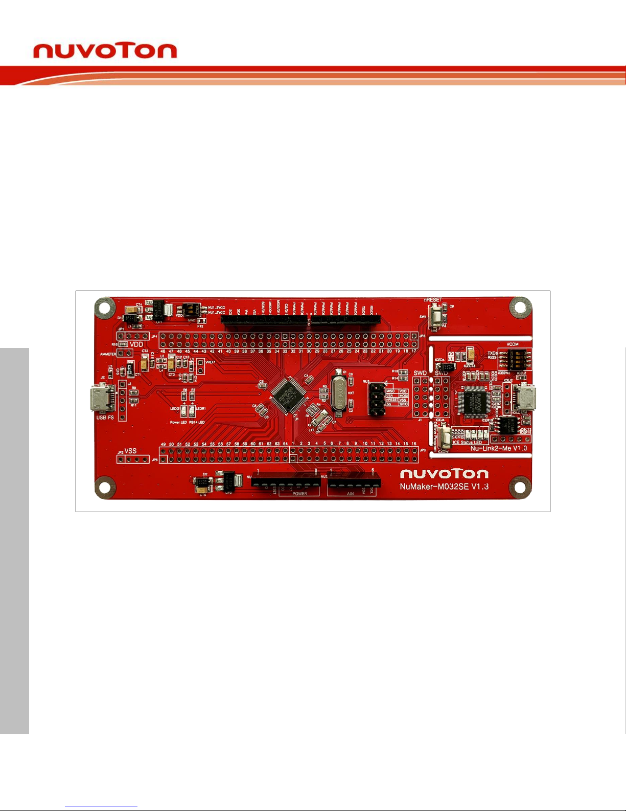
This user manual is aimed to give users a fast introduction to the use of NuMaker-M032SE board.
The NuMaker-M032SE consists of two parts, a M032 platform and an on-board Nu-Link2-Me
debugger and programmer. The NuMaker-M032SE allows users to quickly develop and easily
program and debug application.
The NuMaker-M032SE offers M032SE3AE full pins extension connectors, Arduino UNO compatible
extension connectors and diversified power supply option. It is an easy-to-develop platform for user to
expand the functionality and build the applications. The NuMaker-M032SE also provides an ammeter
connector, allows user to monitor the microcontroller’s power consumption during development.
The Nu-Link2-Me is a debugger and programmer that supports on-line programming and debugging
through SWD interface. The on-board 16 Mbit SPI Flash allows it able to off-line programming the
target microcontroller. Nu-Link2-Me provides virtual COM port (VCOM) function to print out messages
on PC. Nu-Link2-Me can be separated from NuMaker-M032SE, allowing user to use as a mass
production programming tool.
Figure 1-1 NuMaker-M032SE Board
NuMaker-M032SE Features 1.1
NuMicro® M032SE3AE used as main microcontroller with function downward compatible
with:
M032SE3AE
M032LE3AE
M032SE3AE full pins extension connectors
Arduino UNO compatible extension connectors
Ammeter connector for measuring the microcontroller’s power consumption
Fixable board power supply:
External VDD power connector
Arduino UNO compatible extension connector Vin
USB FS connector on M032 platform
Page 7

NuMaker-M032SE
Feb. 20, 2019 Page 7 of 37 Rev 1.00
NUMAKER-M032SE USER MANUAL
Maker Nu-mbed NUC472 User Manual
ICE USB connector on Nu-Link2-Me
On-board Nu-Link2-Me debugger and programmer:
Debug through SWD interface
On-line/off-line programming
Virtual COM port function
Page 8
NuMaker-M032SE
Feb. 20, 2019 Page 8 of 37 Rev 1.00
NUMAKER-M032SE USER MANUAL
Maker Nu-mbed NUC472 User Manual
2 NUMAKER-M032SE OVERVIEW
Front View 2.1
ICE USB Connector
VCOM Switch
Reset Button
ICE Status LED
Off-line Program Button
USB FS Connector
Power LED
PB14 LED
VDD Switch
Target Chip: M032SE3AE Target Chip Extension Connector
Arduino UNO Compatible Extension Connector
External VDD Connector
Nu-Link2-Me
Ammeter
ICE Chip: M48SSIDAE
External VSS Connector
M032 Platform
External V
REF
Connector
Figure 2-1 Front View of NuMaker-M032SE
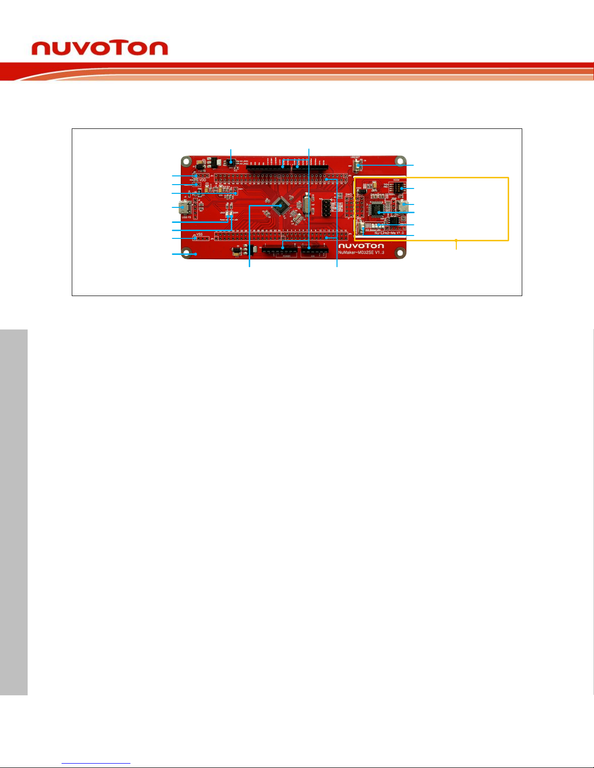
Figure 2-1 shows the main components and connectors from the front side of NuMaker-M032SE. The
following lists components and connectors from the front view:
Target Chip: M032SE3AE(U1)
USB FS Connector(J2)
Arduino UNO Compatible Extension Connectors (NU1, NU2, NU3, NU4)
M031 Extension Connectors (JP3, JP4, JP5 and JP6)
External VDD Power Connector(JP1)
External VSS Power Connector(JP2)
External V
REF
Connector(VREF1)
VDD Switch(SW2)
Ammeter Connector(AMMETER)
Reset Button(SW1)
Power LED and PB14 LED(LEDG1 and LEDR1)
Nu-Link2-Me
VCOM Switch
ICE Chip: M48SSIDAE(ICEU2)
ICE USB Connector(ICEJ3)
ICE Status LED(ICES0,ICES1, ICES2, ICES3)
Off-line Program Button(ICESW1)
Page 9
NuMaker-M032SE
Feb. 20, 2019 Page 9 of 37 Rev 1.00
NUMAKER-M032SE USER MANUAL
Maker Nu-mbed NUC472 User Manual
Rear View 2.2
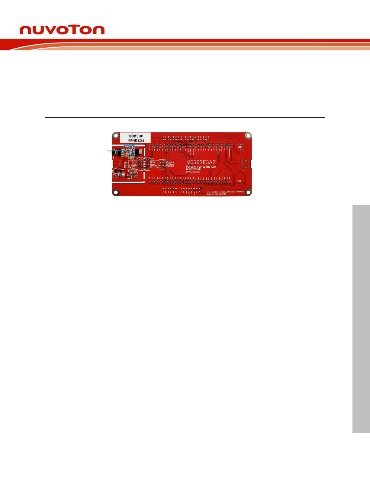
Figure 2-2 shows the main components and connectors from the rear side of NuMaker-M032SE.
The following lists components and connectors from the rear view:
Nu-Link2-Me
MCUVCC Power Switch (ICEJPR1)
ICEVCC Power Switch (ICEJPR2)
ICEVCC Power Switch
MCUVCC Power Switch
Figure 2-2 Rear View of NuMaker-M032SE
Page 10
NuMaker-M032SE
Feb. 20, 2019 Page 10 of 37 Rev 1.00
NUMAKER-M032SE USER MANUAL
Maker Nu-mbed NUC472 User Manual
Arduino UNO Compatible Extension Connectors 2.3
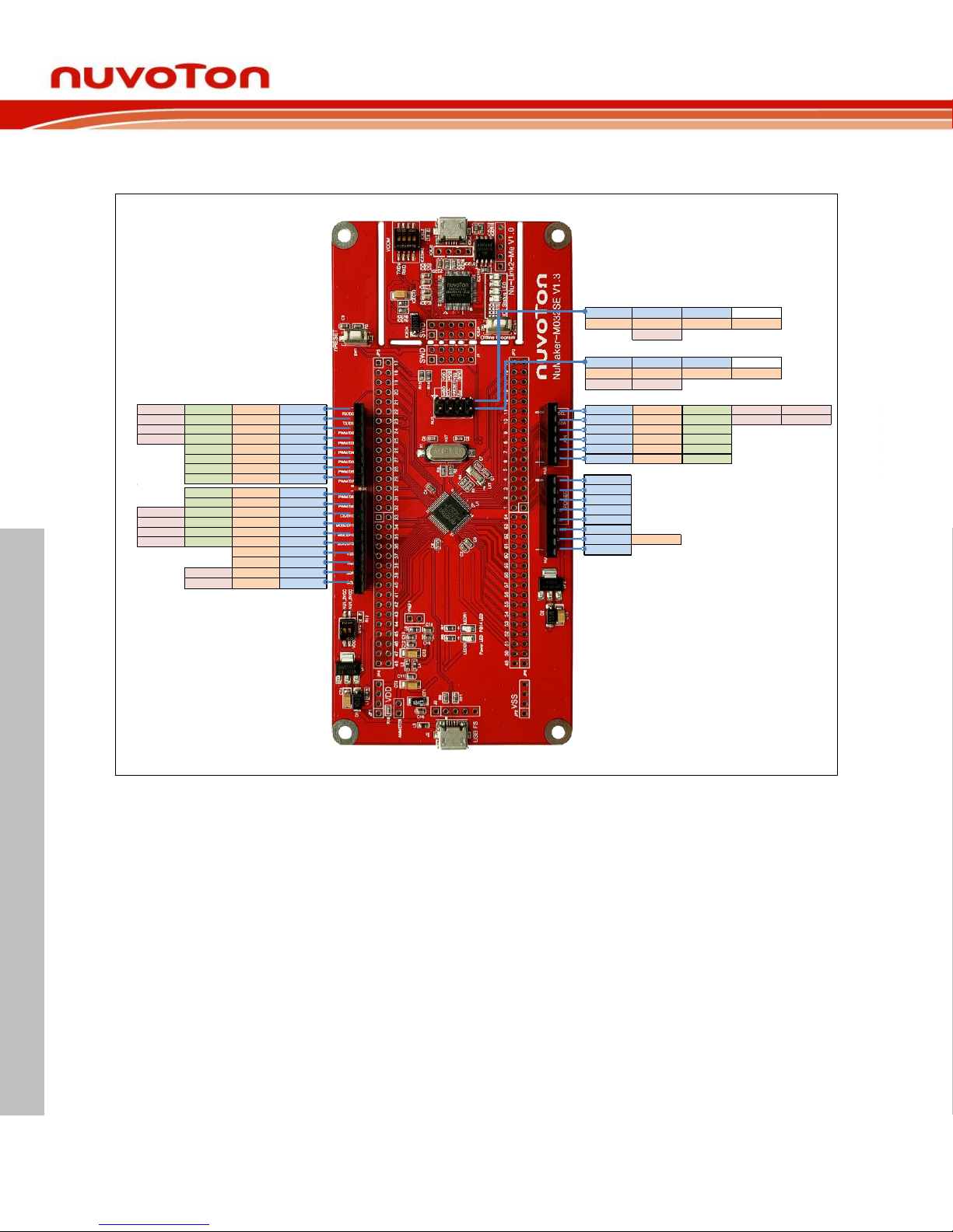
Figure 2-3 shows the Arduino UNO compatible extension connectors.
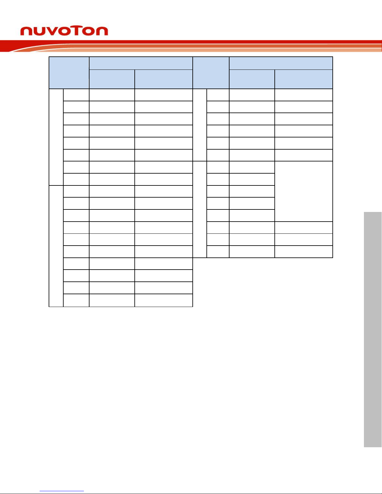
MISO CLK RESET SS
PA.9 PA.11 nRESET PA.8
USCI0_DAT1 USCI0_CLK
5V MOSI GND -
VDD PA.10 VSS PB.15
USCI0_DAT0
PWM0_CH0 PA.5 D8
PWM0_CH1 PA.4 D9
SPI0_SS PWM0_CH2 PA.3 D10
SPI0_MOSI PWM0_CH5 PA.0 D11
SPI0_MISO PWM0_CH4 PA.1 D12
SPI0_CLK PWM0_CH3 PA.2 D13
VSS VSS
VREF VREF
I2C0_SDA PC.0 SDA
I2C0_SCL PC.1 SCL
UART1_RXD PWM0_CH3 PB.2 D0
UART1_TXD PWM0_CH2 PB.3 D1
I2C1_SDA PWM1_CH1 PC.4 D2
I2C1_SCL PWM1_CH0 PC.5 D3
PWM1_CH2 PC.3 D4
PWM1_CH3 PC.2 D5
PWM1_CH4 PA.7 D6
PWM1_CH5 PA.6 D7
VIN
VSS
VSS
5V
3V
RST
IOREF VDD
NC
A5 PB.1 ADC0_CH1 I2C1_SCL UART2_TXD
A4 PB.0 ADC0_CH0 I2C1_SDA UART2_RXD
A3 PB.4 ADC0_CH4
A2 PB.5 ADC0_CH5
A1 PB.6 ADC0_CH6
A0 PB.7 ADC0_CH7
Figure 2-3 Arduino UNO Compatible Extension Connectors
Page 11
NuMaker-M032SE
Feb. 20, 2019 Page 11 of 37 Rev 1.00
NUMAKER-M032SE USER MANUAL
Maker Nu-mbed NUC472 User Manual
Header
NuMaker-M032SE
Header
NuMaker-M032SE
Compatible to
Arduino UNO
GPIO Pin of M031
Compatible to
Arduino UNO
GPIO Pin of M031
N
U
4
NU3.1
D0
PB.2
N
U
2
NU2.6
A5
PB.1
NU3.2
D1
PB.3
NU2.5
A4
PB.0
NU3.3
D2
PC.4
NU2.4
A3
PB.4
NU3.4
D3
PC.5
NU2.3
A2
PB.5
NU3.5
D4
PC.3
NU2.2
A1
PB.6
NU3.6
D5
PC.2
NU2.1
A0
PB.7
NU3.7
D6
PA.7
N
U
1
NU1.8
VIN
-
NU3.8
D7
PA.6
NU1.7
VSS
N
U
3
NU4.1
D8
PA.5
NU1.6
VSS
NU4.2
D9
PA.4
NU1.5
5V
NU4.3
D10
PA.3
NU1.4
3V
NU4.4
D11
PA.0
NU1.3
RST
nRESET
NU4.5
D12
PA.1
NU1.2
IOREF
VDD
NU4.6
D13
PA.2
NU1.1
NC
-
NU4.7
VSS
VSS
NU4.8
VREF
V
REF
NU4.9
SDA
PC.0
NU4.10
SCL
PC.1
Table 2-1 Arduino UNO Extension Connectors and M032SE3AE Mapping GPIO List
Page 12
NuMaker-M032SE
Feb. 20, 2019 Page 12 of 37 Rev 1.00
NUMAKER-M032SE USER MANUAL
Maker Nu-mbed NUC472 User Manual
Pin Assignment for Extension Connectors 2.4
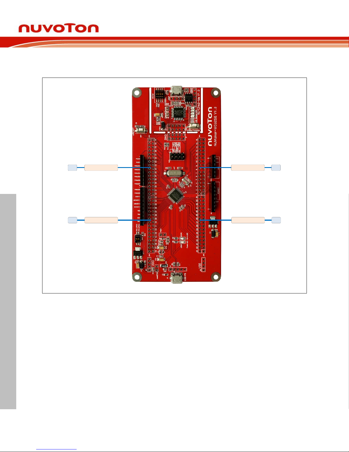
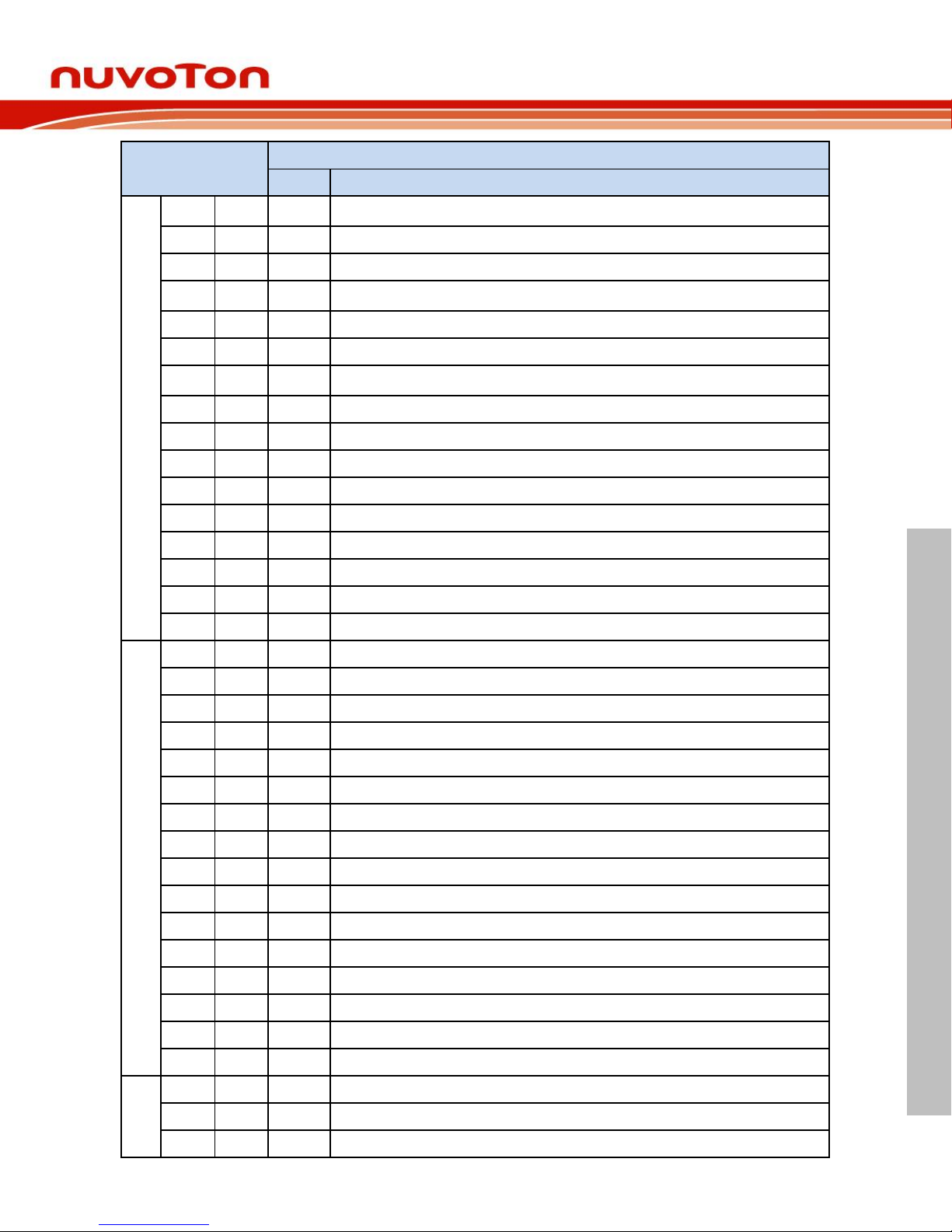
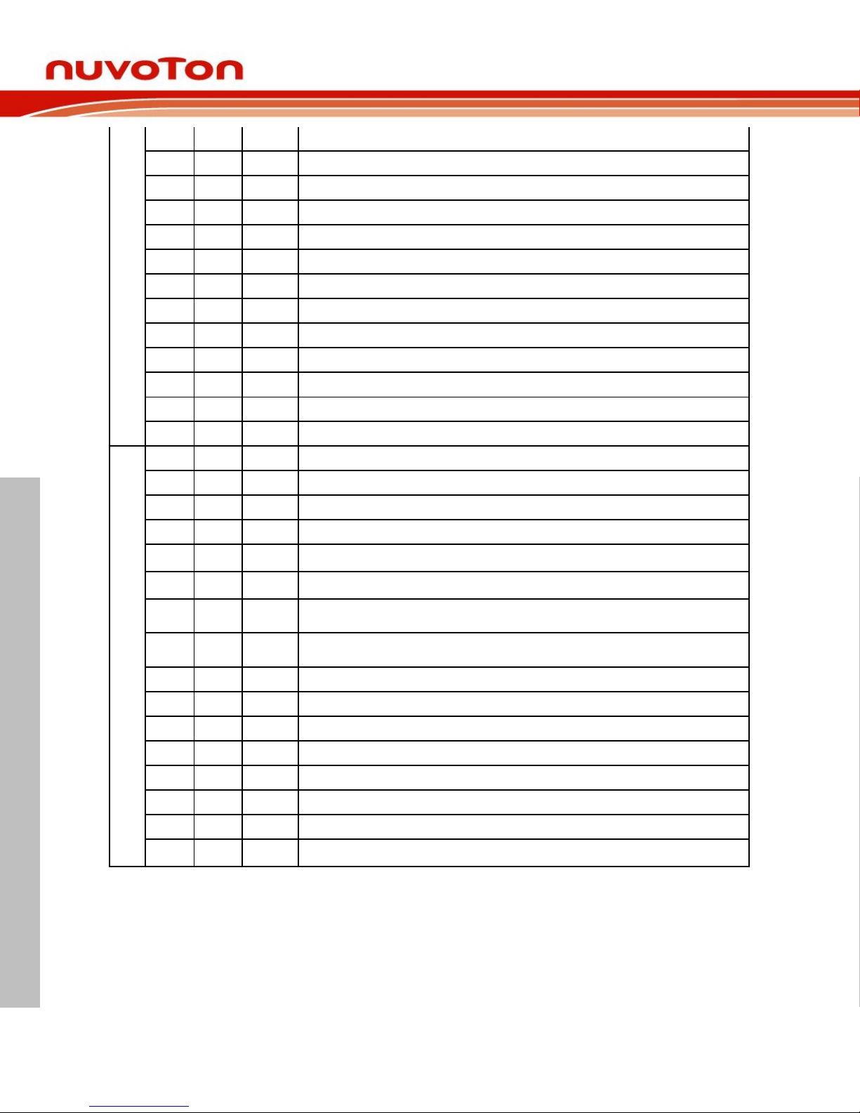
The NuMaker-M032SE provides the M032SE3AE target chip onboard and full pins extension
connectors (JP3, JP4, JP5 and JP6). The Figure 2-4 shows the M032SE3AE extension connectors.
JP3
Pin1 ~ Pin16
JP6
Pin49 ~ Pin64
JP5
Pin17 ~ Pin32
JP4
Pin33 ~ Pin48
Figure 2-4 M032SE3AE Extension Connectors
Page 13
NuMaker-M032SE
Feb. 20, 2019 Page 13 of 37 Rev 1.00
NUMAKER-M032SE USER MANUAL
Maker Nu-mbed NUC472 User Manual
Header
M032SE3AE
Pin No.
Function
JP3
JP3.1
JP3.2
1
PB.6/ADC0_CH6/EBI_nWRH/UART1_RXD/EBI_nCS1/PWM1_BRAKE1/PWM1_CH5/INT
4/ACMP1_O
JP3.3
JP3.4
2
PB.5/ADC0_CH5/ACMP1_N/I2C0_SCL/PWM0_CH0/UART2_TXD/TM0/INT0
JP3.5
JP3.6
3
PB.4/ADC0_CH4/ACMP1_P1/I2C0_SDA/PWM0_CH1/UART2_RXD/TM1/INT1
JP3.7
JP3.8
4
PB.3/ADC0_CH3/ACMP0_N/I2C1_SCL/UART1_TXD/PWM0_CH2/PWM0_BRAKE0/TM2
/INT2
JP3.9
JP3.10
5
PB.2/ADC0_CH2/ACMP0_P1/I2C1_SDA/UART1_RXD/PWM0_CH3/TM3/INT3
JP3.11
JP3.12
6
PB.1/ADC0_CH1/UART2_TXD/I2C1_SCL/PWM0_CH4/PWM1_CH4/PWM0_BRAKE0
JP3.13
JP3.14
7
PB.0/ADC0_CH0/UART2_RXD/SPI0_I2SMCLK/I2C1_SDA/PWM0_CH5/PWM1_CH5/PW
M0_BRAKE1
JP3.15
JP3.16
8
PA.11/ACMP0_P0/EBI_nRD/USCI0_CLK/TM0_EXT
JP3.17
JP3.18
9
PA.10/ACMP1_P0/EBI_nWR/USCI0_DAT0/TM1_EXT
JP3.19
JP3.20
10
PA.9/EBI_MCLK/USCI0_DAT1/UART1_TXD/TM2_EXT
JP3.21
JP3.22
11
PA.8/EBI_ALE/USCI0_CTL1/UART1_RXD/TM3_EXT/INT4
JP3.23
JP3.24
12
PF.6/EBI_ADR19/SPI0_MOSI/EBI_nCS0
JP3.25
JP3.26
13
PF.14/PWM1_BRAKE0/PWM0_BRAKE0/PWM0_CH4/CLKO/TM3/INT5
JP3.27
JP3.28
14
PF.5/UART2_RXD/UART2_nCTS/PWM0_CH0/X32_IN/ADC0_ST
JP3.29
JP3.30
15
PF.4/UART2_TXD/UART2_nRTS/PWM0_CH1/X32_OUT
JP3.31
JP3.32
16
PF.3/EBI_nCS0/UART0_TXD/I2C0_SCL/XT1_IN
JP5
JP5.1
JP5.2
17
PF.2/EBI_nCS1/UART0_RXD/I2C0_SDA/XT1_OUT
JP5.3
JP5.4
18
PC.7/EBI_AD9/UART0_nCTS/PWM1_CH2/TM0/INT3
JP5.5
JP5.6
19
PC.6/EBI_AD8/UART0_nRTS/PWM1_CH3/TM1/INT2
JP5.7
JP5.8
20
PA.7/EBI_AD7/UART0_TXD/I2C1_SCL/PWM1_CH4/ACMP0_WLAT/TM2/INT1
JP5.9
JP5.10
21
PA.6/EBI_AD6/UART0_RXD/I2C1_SDA/PWM1_CH5/ACMP1_WLAT/TM3/INT0
JP5.11
JP5.12
22
VSS
JP5.13
JP5.14
23
VDD
JP5.15
JP5.16
24
PD.15/PWM0_CH5/TM3/INT1
JP5.17
JP5.18
25
PA.5/UART0_nCTS/UART0_TXD/I2C0_SCL/PWM0_CH0
JP5.19
JP5.20
26
PA.4/SPI0_I2SMCLK/UART0_nRTS/UART0_RXD/I2C0_SDA/PWM0_CH1
JP5.21
JP5.22
27
PA.3/SPI0_SS/UART1_TXD/I2C1_SCL/PWM0_CH2/CLKO/PWM1_BRAKE1
JP5.23
JP5.24
28
PA.2/SPI0_CLK/UART1_RXD/I2C1_SDA/PWM0_CH3
JP5.25
JP5.26
29
PA.1/SPI0_MISO/UART0_TXD/UART1_nCTS/PWM0_CH4
JP5.27
JP5.28
30
PA.0/SPI0_MOSI/UART0_RXD/UART1_nRTS/PWM0_CH5
JP5.29
JP5.30
31
PF.15/PWM0_BRAKE0/PWM0_CH1/TM2/CLKO/INT4
JP5.31
JP5.32
32
nRESET
JP4
JP4.1
JP4.2
33
PF.0/UART1_TXD/I2C1_SCL/UART0_TXD/ICE_DAT
JP4.3
JP4.4
34
PF.1/UART1_RXD/I2C1_SDA/UART0_RXD/ICE_CLK
JP4.5
JP4.6
35
PC.5/EBI_AD5/UART2_TXD/I2C1_SCL/PWM1_CH0
Page 14
NuMaker-M032SE
Feb. 20, 2019 Page 14 of 37 Rev 1.00
NUMAKER-M032SE USER MANUAL
Maker Nu-mbed NUC472 User Manual
JP4.7
JP4.8
36
PC.4/EBI_AD4/UART2_RXD/I2C1_SDA/PWM1_CH1
JP4.9
JP4.10
37
PC.3/EBI_AD3/UART2_nRTS/PWM1_CH2
JP4.11
JP4.12
38
PC.2/EBI_AD2/UART2_nCTS/PWM1_CH3
JP4.13
JP4.14
39
PC.1/EBI_AD1/UART2_TXD/I2C0_SCL/PWM1_CH4/ACMP0_O
JP4.15
JP4.16
40
PC.0/EBI_AD0/UART2_RXD/I2C0_SDA/PWM1_CH5/ACMP1_O
JP4.17
JP4.18
41
PD.3/EBI_AD10/USCI0_CTL1/SPI0_SS/UART0_TXD
JP4.19
JP4.20
42
PD.2/EBI_AD11/USCI0_DAT1/SPI0_CLK/UART0_RXD
JP4.21
JP4.22
43
PD.1/EBI_AD12/USCI0_DAT0/SPI0_MISO
JP4.23
JP4.24
44
PD.0/EBI_AD13/USCI0_CLK/SPI0_MOSI/TM2
JP4.25
JP4.26
45
USB_VBUS
JP4.27
JP4.28
46
USB_D-
JP4.29
JP4.30
47
USB_D+
JP4.15
JP4.32
48
USB_VDD33_CAP
JP6
JP6.1
JP6.2
49
VSS
JP6.3
JP6.4
50
LDO_CAP
JP6.5
JP6.6
51
VDD
JP6.7
JP6.8
52
PC.14/EBI_AD11/SPI0_I2SMCLK/USCI0_CTL0/TM1
JP6.9
JP6.10
53
PB.15/ADC0_CH15/EBI_AD12/SPI0_SS/USCI0_CTL1/UART0_nCTS/PWM1_CH0/TM0_
EXT/PWM0_BRAKE1
JP6.11
JP6.12
54
PB.14/ADC0_CH14/EBI_AD13/SPI0_CLK/USCI0_DAT1/UART0_nRTS/PWM1_CH1/TM1
_EXT/CLKO
JP6.13
JP6.14
55
PB.13/ADC0_CH13/ACMP0_P3/ACMP1_P3/EBI_AD14/SPI0_MISO/USCI0_DAT0/UART
0_TXD/PWM1_CH2/TM2_EXT
JP6.15
JP6.16
56
PB.12/ADC0_CH12/ACMP0_P2/ACMP1_P2/EBI_AD15/SPI0_MOSI/USCI0_CLK/UART0
_RXD/PWM1_CH3/TM3_EXT
JP6.17
JP6.18
57
AVDD
JP6.19
JP6.20
58
VREF
JP6.21
JP6.22
59
AVSS
JP6.23
JP6.24
60
PB.11/ADC0_CH11/EBI_ADR16/UART0_nCTS/I2C1_SCL/SPI0_I2SMCLK
JP6.25
JP6.26
61
PB.10/ADC0_CH10/EBI_ADR17/UART0_nRTS/I2C1_SDA
JP6.27
JP6.28
62
PB.9/ADC0_CH9/EBI_ADR18/UART0_TXD/UART1_nCTS
JP6.29
JP6.30
63
PB.8/ADC0_CH8/EBI_ADR19/UART0_RXD/UART1_nRTS
JP6.15
JP6.32
64
PB.7/ADC0_CH7/EBI_nWRL/UART1_TXD/EBI_nCS0/PWM1_BRAKE0/PWM1_CH4/INT
5/ACMP0_O
Table 2-2 M032SE3AE Full-pin Extension Connectors and GPIO Function List
Page 15
NuMaker-M032SE
Feb. 20, 2019 Page 15 of 37 Rev 1.00
NUMAKER-M032SE USER MANUAL
Maker Nu-mbed NUC472 User Manual
System Configuration 2.5
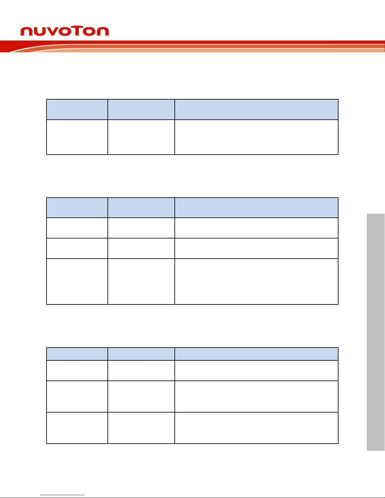
2.5.1 VIN Power Source
Table 2-3 presents the Vin power source.
Connector
Net Name in
Schematic
Comment
NU1 pin8
NU1_VIN
Board external power source, with voltage range from 7
V to 12 V. The voltage regulator UP2 converts the NU1
pin8 input voltage to 5 V and supplies it to NuMakerM032SE.
Table 2-3 Vin Power Source
2.5.2 5 V Power Sources
Table 2-4 presents the 5 V power sources.
Connector
Net Name in
Schematic
Comment
ICEJ3
USB_HS_VBUS
ICE USB connector supplies 5 V power from PC to
M032 platform and Nu-Link2-Me.
J2
USB_VBUS
USB connector on NuMaker-M032SE supplies 5 V
power from PC to M032 platform and Nu-Link2-Me.
NU1 pin5
NU1_5VCC
ICEJ3, J2 or NU1 pin8 supplies 5 V power to NU1 pin5.
NU1 pin5 supplies 5 V power to target chip or Arduino
adapter board.
Note: M031 operating voltage range is from 1.8 V to 3.6
V. Do not switch SW2.1(NU1 5VCC) to ON.
Table 2-4 5V Power Sources
2.5.3 3.3 V Power Sources
Table 2-5 presents the 3.3 V power sources.
Voltage Regulator
5V Source
Comment
ICEUP1
USB_HS_VBUS
ICEUP1 converts USB_HS_VBUS to 3.3 V and supplies
3.3V to M032 platform or ICE chip.
UP1
USB_VBUS
UP1 converts USB_VBUS to 3.3 V and supplies 3.3 V
to M032 platform.
Note: SW2.2(NU1 3VCC) should be switched to ON.
UP1
NU1_5VCC
UP1 converts NU1_5VCC to 3.3 V and supplies 3.3 V to
M032 platform.
Note: SW2.2(NU1 3VCC) should be switched to ON.
Table 2-5 3.3 V Power Sources
Page 16
NuMaker-M032SE
Feb. 20, 2019 Page 16 of 37 Rev 1.00
NUMAKER-M032SE USER MANUAL
Maker Nu-mbed NUC472 User Manual
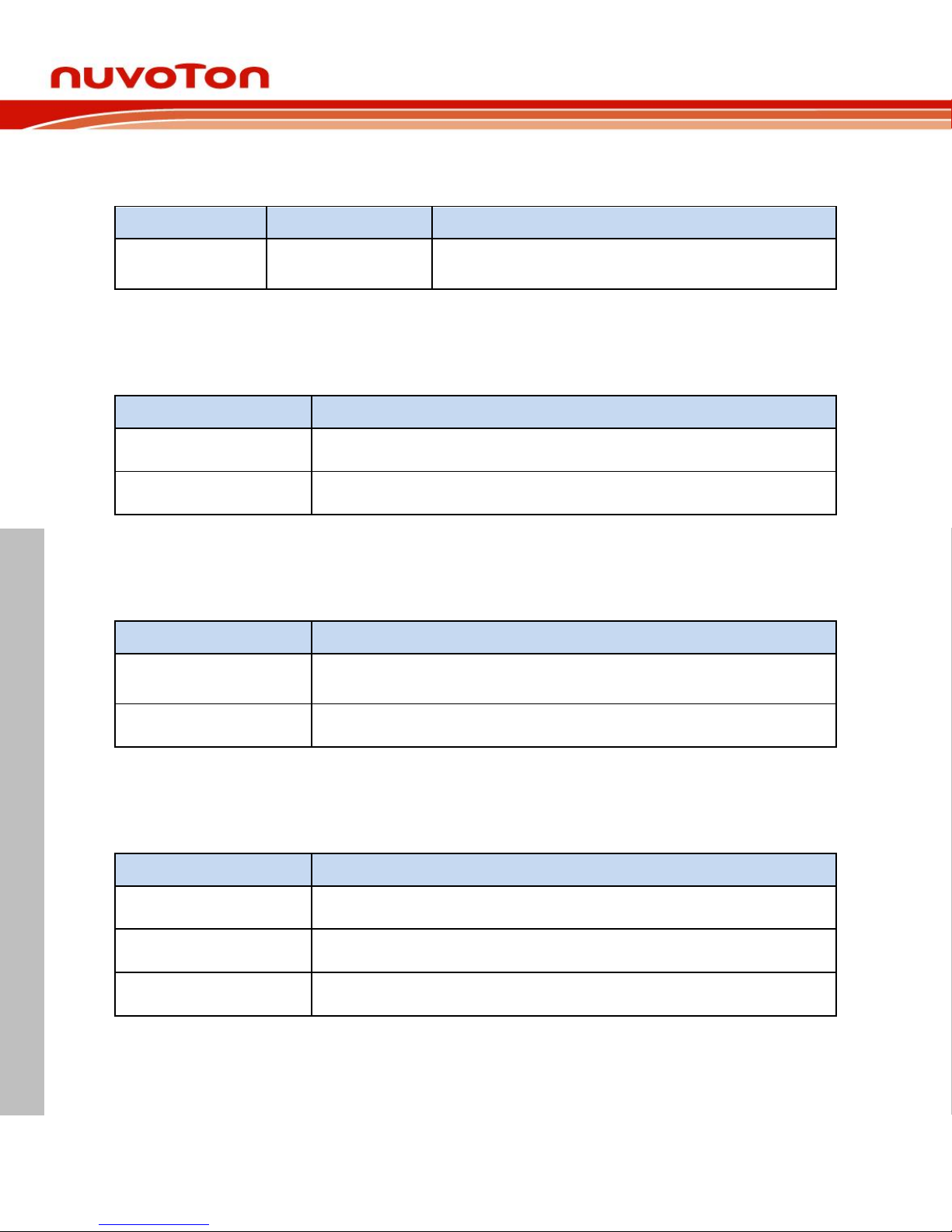
2.5.4 1.8V Power Sources
Table 2-6 presents the 1.8 V power source.
Voltage Regular
5V Source
Comment
ICEUP2
USB_HS_VBUS
ICEUP2 converts USB_HS_VBUS to 1.8V and supplies
1.8V to M032 platform or ICE chip.
Table 2-6 1.8V Power Sources
2.5.5 Power Connectors
Table 2-7 presents the power connectors.
Connector
Comment
JP1
VDD (1.8 V ~ 3.6 V) connector on the NuMaker-M032SE.
JP2
VSS connector on the NuMaker-M032SE.
Table 2-7 Power Connectors
2.5.6 USB Connectors
Table 2-8 presents the USB connectors.
Connector
Comment
ICEJ3
ICE USB connector on Nu-Link2-Me for power supply, debugging and
programming from PC.
J2
USB FS connector on NuMaker-M032SE for power supply.
Table 2-8 USB Connectors
2.5.7 Power Switches
Table 2-9 presents the power switches.
Switch
Comment
ICEJPR1
Configures the target chip operating voltage at 1.8 V / 3.3 V / 5 V.
ICEJPR2
Configures the ICE chip operating voltage at 1.8 V / 3.3 V.
SW2
Configures the target chip operating voltage at 3.3 V / 5 V.
Table 2-9 Power Switches
Page 17
NuMaker-M032SE
Feb. 20, 2019 Page 17 of 37 Rev 1.00
NUMAKER-M032SE USER MANUAL
Maker Nu-mbed NUC472 User Manual
2.5.8 Power Supply Models
External Power Supply through Nu-Link2-Me to Target Chip 2.5.8.1
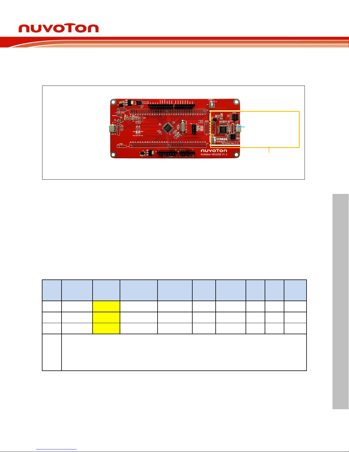
The external power supply source on Nu-Link2-Me is shown in Figure 2-5.
ICE USB Connector (ICEJ3)
Nu-Link2-Me
Figure 2-5 External Power Supply Sources on Nu-Link2-Me
To use ICEJ3 as external power supply source with Nu-Link2-Me, please follow the below steps:
1. Solder the resistor on ICEJPR1 (MCUVCC) depends on the target chip operating voltage.
2. Solder the resistor on ICEJPR2 (ICEVCC) depends on the ICE chip operating voltage.
3. Switch the SW2 to OFF.
4. Connect the external power supply to JP1.
Table 2-10 presents all power models when supplies external power through Nu-Link2-Me. The NuLink2-Me external power sources are highlighted in yellow.
Model
Target
Chip
Voltage
ICEJ3
ICEJPR1
(MCUVCC)
Selection
[1]
ICEJPR2
(ICEVCC)
Selection
[2]
ICE
Chip
Voltage
SW2
Selection
J2
Vin
JP1
1
1.8 V
Connect
to PC
1.8 V
1.8 V
1.8 V
Off
Ignore
Ignore
1.8 V
output
2
3.3 V
Connect
to PC
3.3 V (default)
3.3 V (default)
3.3 V
Off
Ignore
Ignore
3.3 V
output
3
5 V
Connect
to PC
5V
3.3 V (default)
3.3 V
Off
Ignore
Ignore
5 V
output
X: Unused.
Note:
1. 0 Ω should be soldered between ICEJPR1’s MCUVCC and 1.8 V / 3.3 V / 5 V.
2. 0 Ω should be soldered between ICEJPR2’s ICEVCC and 1.8 V / 3.3 V.
Table 2-10 Supply External Power through Nu-Link2-Me
Page 18
NuMaker-M032SE
Feb. 20, 2019 Page 18 of 37 Rev 1.00
NUMAKER-M032SE USER MANUAL
Maker Nu-mbed NUC472 User Manual
External Power Supply through M032 platform to Target Chip 2.5.8.2
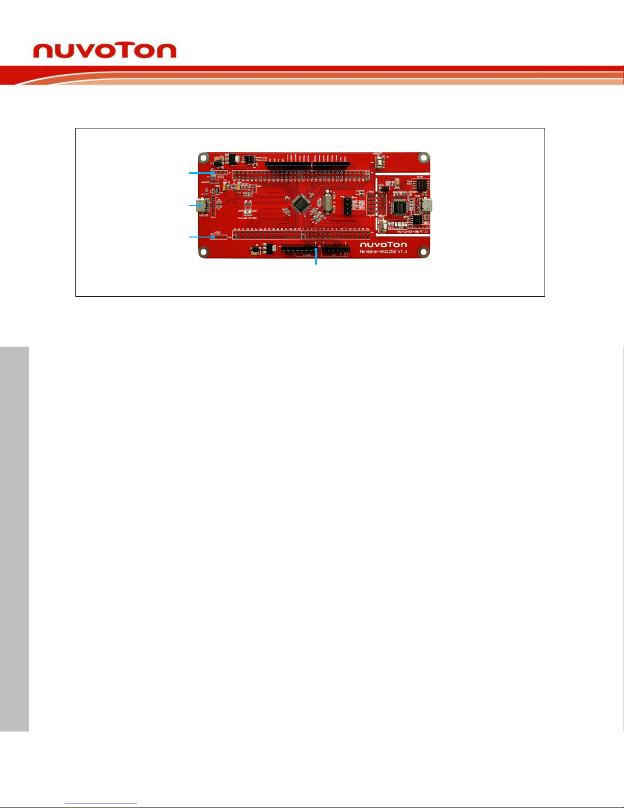
The external power supply sources on M032 platform are shown in Figure 2-6.
USB Power Connector (J2)
NU1 pin8 (Vin)
External VDD Connector (JP1)
External VSS Connector (JP2)
Figure 2-6 External Power Supply Sources on M032 platform
To use Vin or J2 as external power supply source, please follow the below steps:
1. Switch the SW2 depends on the target chip operating voltage.
2. Remove the resistor on ICEJPR1 (MCUVCC).
3. Solder the resistor on ICEJPR2 (ICEVCC) depends on the ICE chip operating voltage.
4. Connect the external power supply to Vin or J2.
To use JP1 as external power supply source, please follow the below steps:
1. Switch the SW2 to OFF.
2. Remove the resistor on ICEJPR1 (MCUVCC).
3. Solder the resistor on ICEJPR2 (ICEVCC) depends on the ICE chip operating voltage.
4. Connect ICEJ3 to PC.
5. Connect the external power supply to JP1.
To use Vin or J2 as external power supply source with Nu-Link2-Me separated from NuMakerM032SE, please follow the below steps:
1. Switch the SW2 depends on the target chip operating voltage.
2. Separate the Nu-Link2-Me from NuMaker-M032SE.
3. Connect the external power supply to Vin or J2.
To use JP1 as external power supply source with Nu-Link2-Me separated from NuMaker-M032SE,
please follow the below steps:
1. Switch the SW2 to OFF.
2. Separate the Nu-Link2-Me from NuMaker-M032SE.
3. Connect the external power supply to JP1.
Page 19
NuMaker-M032SE
Feb. 20, 2019 Page 19 of 37 Rev 1.00
NUMAKER-M032SE USER MANUAL
Maker Nu-mbed NUC472 User Manual
USB Power Connector (J2)
NU1 pin8 (Vin)
External VDD Connector (JP1)
External VSS Connector (JP2)
Separate Nu-Link2-Me
"
"
Figure 2-7 Separate the Nu-Link2-Me from NuMaker-M032SE
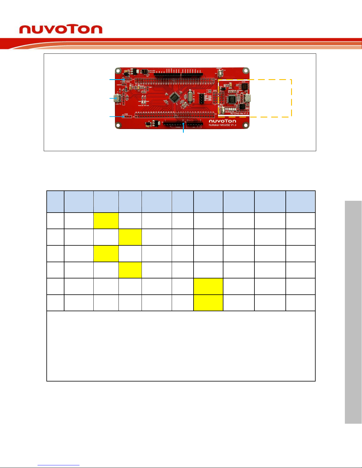
Table 2-11 presents all power models when supplies external power through M032 platform. The
M032 platform external power sources are highlighted in yellow.
Model
Target Chip
Voltage
Vin
[1]
J2
ICEJ3
SW2
Selection
JP1
ICEJPR1
(MCUVCC)
Selection
[2]
ICEJPR2
(ICEVCC)
Selection
[3]
ICE Chip
Voltage
[4]
4
3.3 V
7 V ~ 12 V
Input
X
Ignore
NU1
3VCC
3.3 V output
Remove
resistor
3.3 V
3.3 V
5
3.3 V
X
Connect
to PC
Ignore
NU1
3VCC
3.3 V output
Remove
resistor
3.3 V
3.3 V
6
5 V
7 V ~ 12 V
Input
X
Ignore
NU1
5VCC
5 V output
Remove
resistor
3.3 V
3.3 V 7 5 V
X
Connect
to PC
Ignore
NU1
5VCC
5 V output
Remove
resistor
3.3 V
3.3 V
8
1.8 V ~ 3.6 V
Ignore
[5]
Ignore
[5]
Connect to
PC
OFF
DC Input
1.8 V ~ 3.6 V
Remove
resistor
1.8 V / 3.3 V
1.8 V / 3.3 V
9
1.8 V ~ 3.6 V
Ignore
[5]
Ignore
[5]
Nu-Link2-Me
removed
OFF
DC Input
1.8 V ~ 3.6 V
X X X
X: Unused.
Note:
1. The Vin input voltage will be converted by voltage regulator UP2 to 5 V.
2. 0Ω should be removed from ICEJPR1’s MCUVCC and 1.8 V / 3.3 V / 5 V.
3. 0Ω should be soldered between ICEJPR2’s ICEVCC and 1.8 V / 3.3 V.
4. The ICE chip voltage should be close to the target chip voltage.
5. JP1 external power input only provides voltage to target chip. Supply external power to Vin or J2 can provide
5V to NU1 pin5 (5V) and 3.3V to NU1 pin4 (3VCC).
Table 2-11 Supply External Power for M032 platform
Page 20
NuMaker-M032SE
Feb. 20, 2019 Page 20 of 37 Rev 1.00
NUMAKER-M032SE USER MANUAL
Maker Nu-mbed NUC472 User Manual
2.5.9 External Reference Voltage Connector
Table 2-13 presents the external reference voltage connector.
Connector
Comment
VREF1
Connector for user to easily connect to the external reference voltage pin
of the target chip. User needs to remove the L5 ferrite bead.
Table 2-12 External Reference Voltage Connector
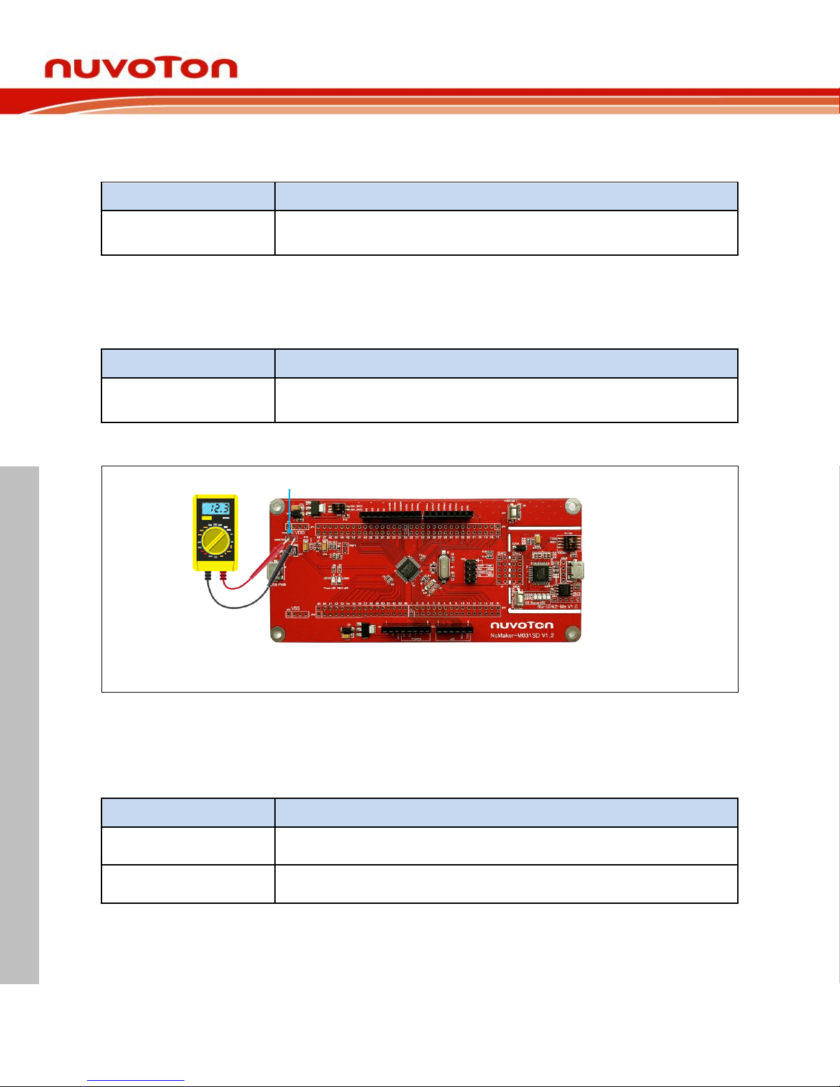
2.5.10 Ammeter Connector
Table 2-13 presents the ammeter connector.
Connector
Comment
AMMETER
Connector for user to easily measure the target chip power consumption.
User needs to remove the R16 resistor.
Table 2-13 Ammeter Connector
Remove the R16 Resistor
Figure 2-8 Wiring between Ammeter Connector and Ammeter
2.5.11 Extension Connectors
Table 2-14 presents the extension connectors.
Connector
Comment
JP3, JP4, JP5 and JP6
Full pins extension connectors on the NuMaker-M032SE.
NU1, NU2, NU3 and NU4
Arduino UNO compatible pins on the NuMaker-M032SE.
Table 2-14 Extension Connectors
Page 21
NuMaker-M032SE
Feb. 20, 2019 Page 21 of 37 Rev 1.00
NUMAKER-M032SE USER MANUAL
Maker Nu-mbed NUC472 User Manual
2.5.12 Push-Buttons
Table 2-15 presents the push-buttons.
Component
Comment
ICESW1
Off-line program button to start off-line programming the target chip.
SW1
Reset button to reset the target chip.
Table 2-15 Push-Buttons
2.5.13 LEDs
Table 2-16 presents the LEDs.
Component
Comment
Power LED
The power LED indicates that the NuMaker-M032SE is powered.
PB14 LED
The LED is connected to the target chip PB.14.
ICES0, ICES1, ICES2
and ICES3
Nu-Link2-Me status LED.
Table 2-16 LEDs
Nu-Link2-Me 2.6
The Nu-Link2-Me is a debugger and programmer that supports on-line programming and debugging
through SWD interface. The on-board 16 Mbit SPI Flash allows it to off-line program the target
microcontroller. Additionally, the Nu-Link2-Me provides virtual COM port (VCOM) function to print out
messages on PC. Table 2-17 presents how to set the VCOM function by ICESW2.
ICESW2
Pin
Function
Comment
1
TXD
On: Connect target chip PB.13 (UART0_TXD) to Nu-Link2-Me.
Off: Disconnect target chip PB.13 (UART0_TXD) to Nu-Link2-Me.
2
RXD
On: Connect target chip PB.12 (UART0_RXD) to Nu-Link2-Me.
Off: Disconnect target chip PB.12 (UART0_RXD) to Nu-Link2-Me.
Note: Pin 3 and 4 is unused.
Table 2-17 VCOM Function of Nu-Link2-Me
Page 22
NuMaker-M032SE
Feb. 20, 2019 Page 22 of 37 Rev 1.00
NUMAKER-M032SE USER MANUAL
Maker Nu-mbed NUC472 User Manual
PCB Placement 2.7
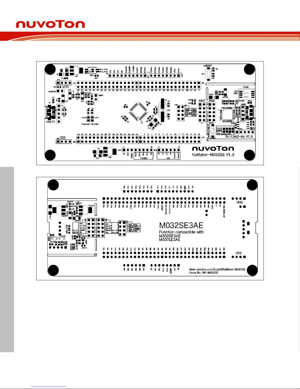
Figure 2-9 and Figure 2-10 show the front and rear placement of NuMaker-M032SE.
Figure 2-9 Front Placement
Figure 2-10 Rear Placement
Page 23
NuMaker-M032SE
Feb. 20, 2019 Page 23 of 37 Rev 1.00
NUMAKER-M032SE USER MANUAL
Maker Nu-mbed NUC472 User Manual
3 QUICK START
Toolchains Supporting 3.1
Install the preferred toolchain. Please make sure at least one of the toolchains has been installed.
KEIL MDK Nuvoton edition M0/M23
IAR EWARM
NuEclipse (GCC)(Windows)
NuEclipse (GCC)(Linux)
Nuvoton Nu-Link Driver Installation 3.2
Download and install the latest Nuvoton Nu-Link Driver.
Download and install Nu-Link_Keil_Driver when using Keil MDK.
Download and install Nu-Link_IAR_Driver when using IAR EWARM.
Skip this step when using NuEclipse.
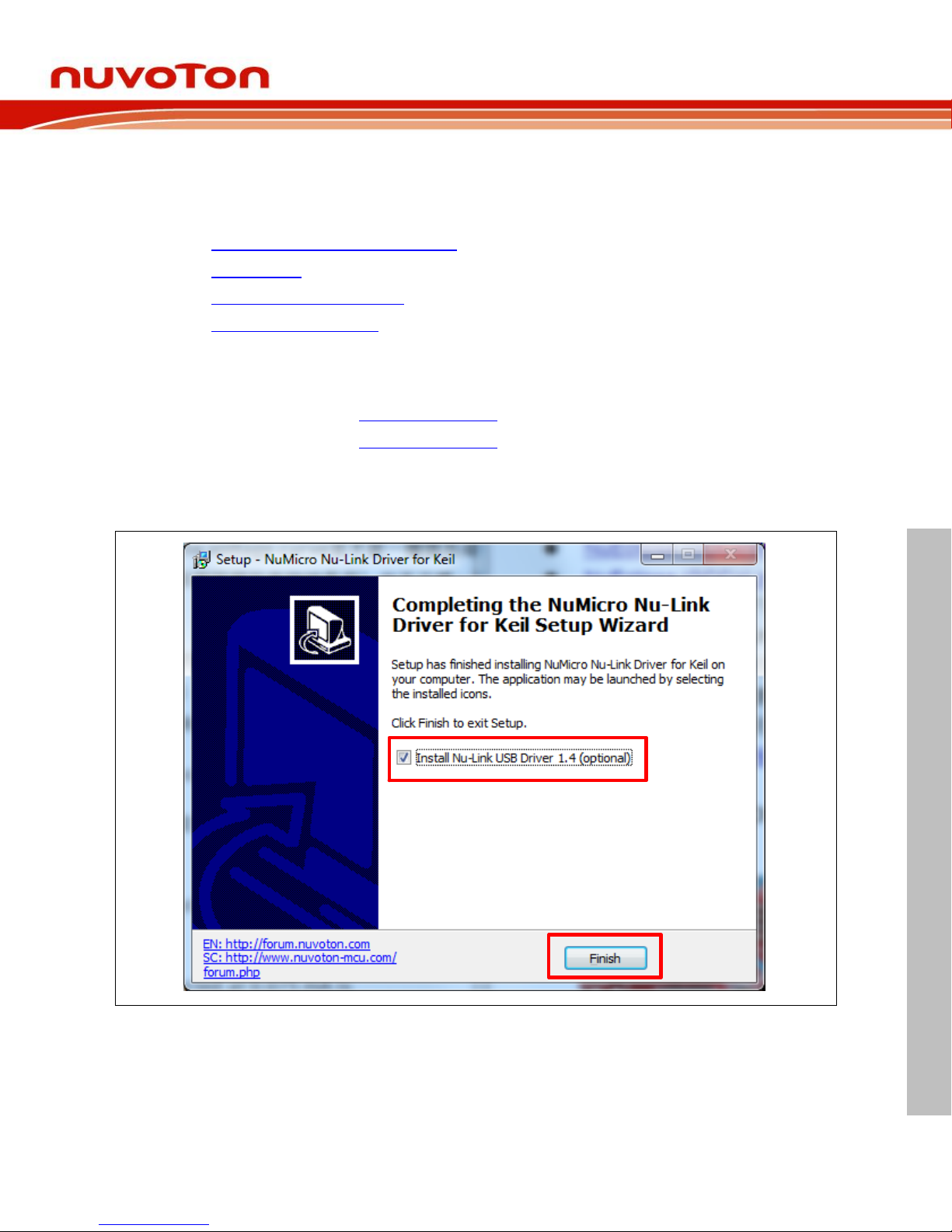
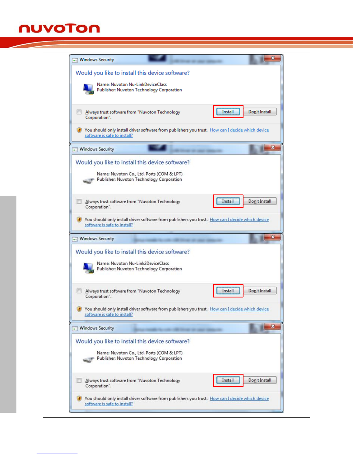
Please install the Nu-Link USB Driver as well at the end of the installation. The installation is
presented in Figure 3-1 and Figure 3-2.
Figure 3-1 Nu-Link USB Driver Installation Setup
Page 24
NuMaker-M032SE
Feb. 20, 2019 Page 24 of 37 Rev 1.00
NUMAKER-M032SE USER MANUAL
Maker Nu-mbed NUC472 User Manual
Figure 3-2 Nu-Link USB Driver Installation
Page 25
NuMaker-M032SE
Feb. 20, 2019 Page 25 of 37 Rev 1.00
NUMAKER-M032SE USER MANUAL
Maker Nu-mbed NUC472 User Manual
BSP Firmware Download 3.3
Download and unzip the Board Support Package (BSP).
Hardware Setup 3.4
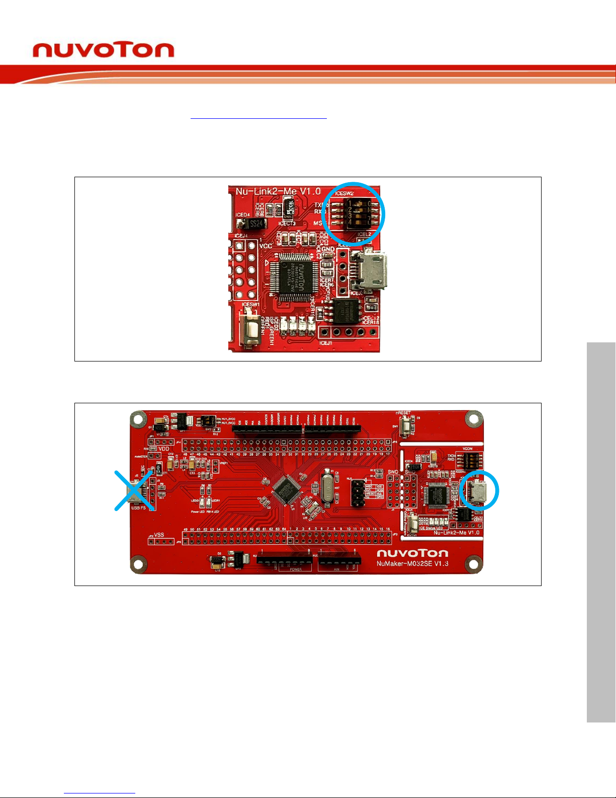
1. Open the virtual COM (VCOM) function by changing Nu-Link2-Me VCOM Switch No. 1 and 2 to
ON.
Figure 3-3 Open VCOM Function
2. Connect the ICE USB connector shown in Figure 3-4 to the PC USB port through USB cable.
Figure 3-4 ICE USB Connector
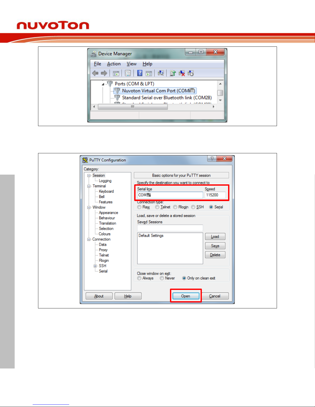
3. Find the “Nuvoton Virtual COM Port” on the Device Manger as Figure 3-5.
Page 26
NuMaker-M032SE
Feb. 20, 2019 Page 26 of 37 Rev 1.00
NUMAKER-M032SE USER MANUAL
Maker Nu-mbed NUC472 User Manual
Figure 3-5 Device Manger
4. Open a serial port terminal, PuTTY for example, to print out debug message. Set the speed to
115200. Figure 3-6 presents the PuTTY session setting.
Figure 3-6 PuTTY Session Setting
Page 27
NuMaker-M032SE
Feb. 20, 2019 Page 27 of 37 Rev 1.00
NUMAKER-M032SE USER MANUAL
Maker Nu-mbed NUC472 User Manual
Find the Example Project 3.5
Use the “Template” project as an example. The project can be found under the BSP folder as shown
in Figure 3-7.
M031_Series_BSP_CMSIS_V3.XX.XXX
SampleCode
Template
GCC
Keil
IAR
Figure 3-7 Template Project Folder Path
Execute the Project under Toolchains 3.6
Open and execute the project under the toolchain. The section 3.6.1, 0, and 3.6.3 describe the steps
of executing project in Keil MDK, IAR EWARM and NuEclipse, respectively.
3.6.1 Keil MDK
This section provides steps to beginners on how to run a project by using Keil MDK.
1. Double click the “Template.uvproj” to open the project.
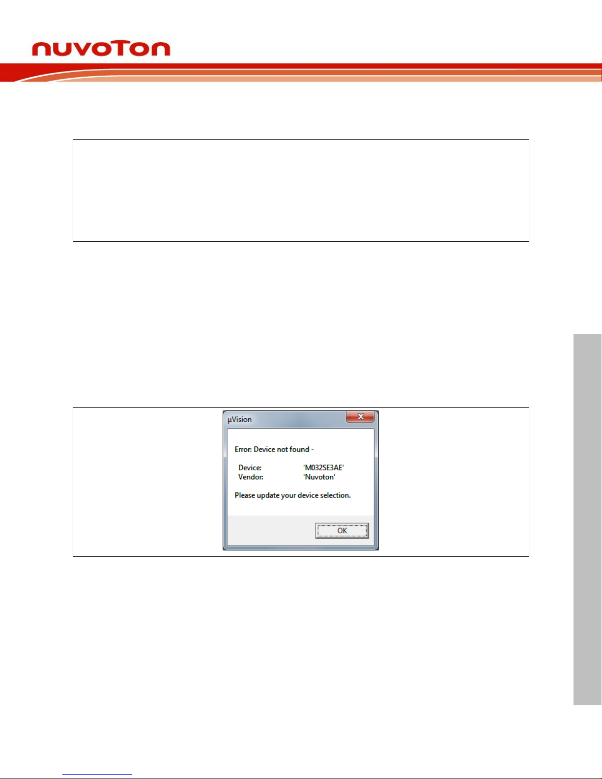
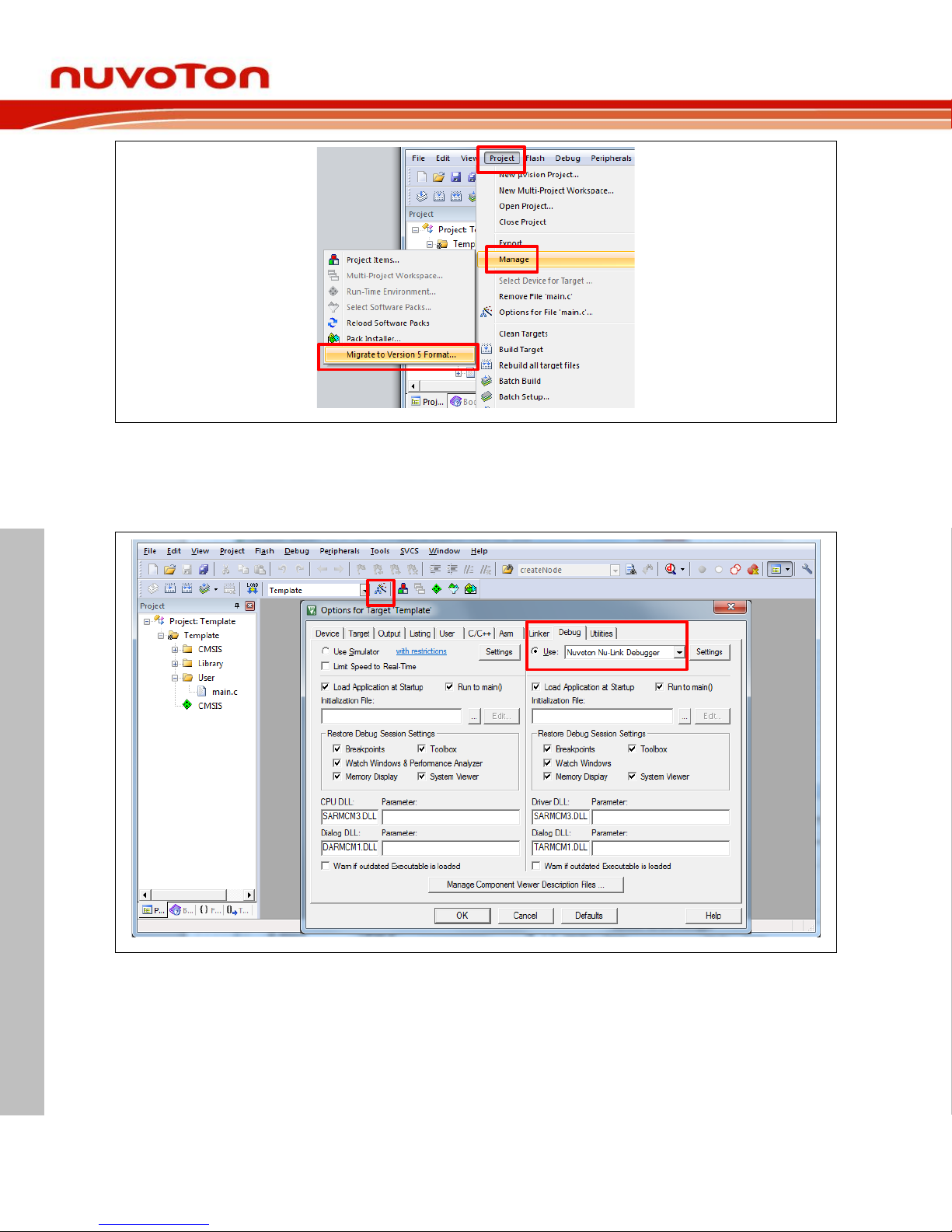
Note: If Figure 3-8 warning message jumps out, please migrate to version 5 formats as shown in
Figure 3-9. The “.uvproj” filename extension will change to “.uvprojx”.
Figure 3-8 Warning Message of “Device not found”
Page 28
NuMaker-M032SE
Feb. 20, 2019 Page 28 of 37 Rev 1.00
NUMAKER-M032SE USER MANUAL
Maker Nu-mbed NUC472 User Manual
1
2
3
Figure 3-9 Project File Migrate to Version 5 Format
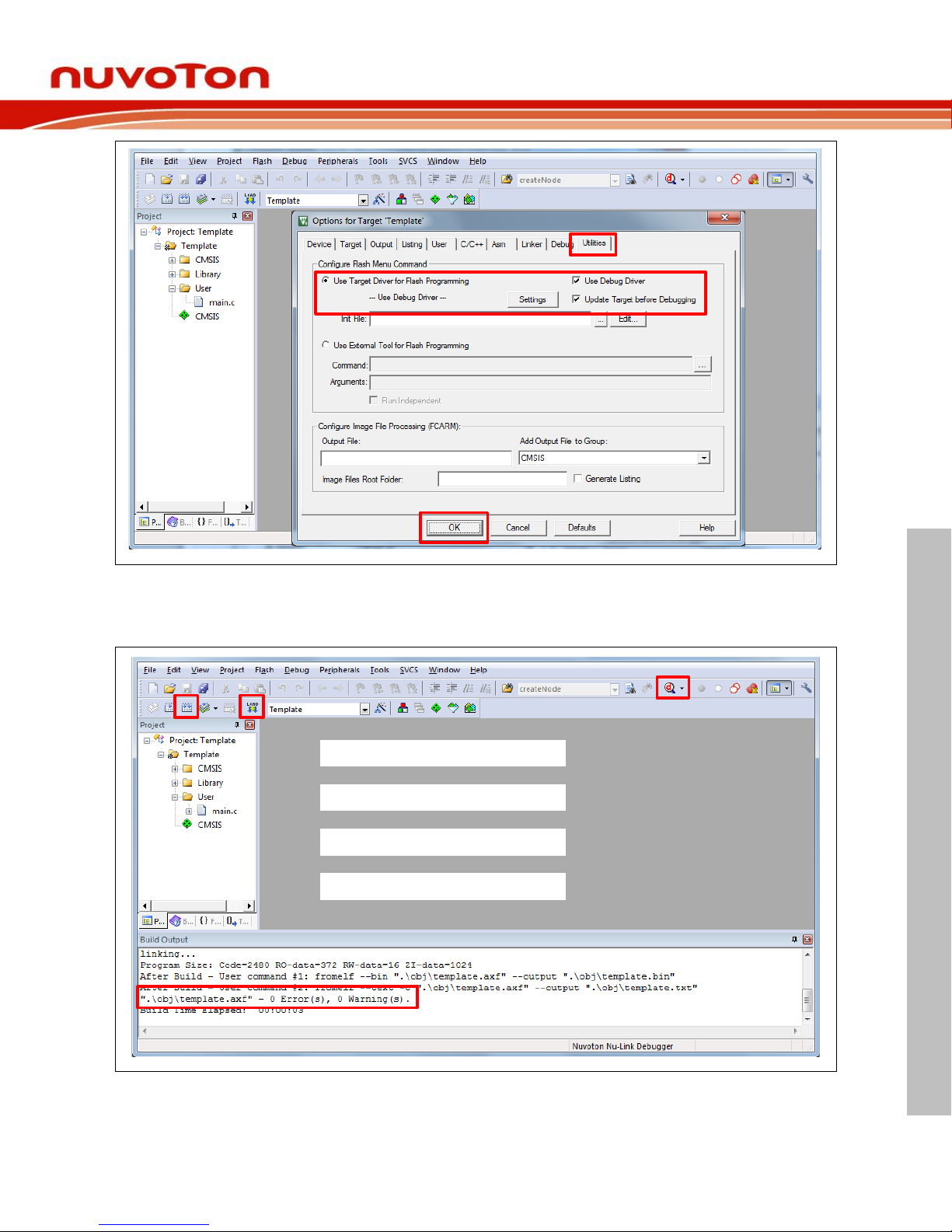
2. Make sure the debugger is “Nuvoton Nu-Link Debugger” as shown in Figure 3-10 and Figure 3-11.
Note: If the dropdown menu in Figure 3-10 does not contain “Nuvoton Nu-Link Debugger” item,
please rework section 3.2.
2
1
Figure 3-10 Debugger Setting in Options Window
Page 29
NuMaker-M032SE
Feb. 20, 2019 Page 29 of 37 Rev 1.00
NUMAKER-M032SE USER MANUAL
Maker Nu-mbed NUC472 User Manual
3
4
5
Figure 3-11 Programming Setting in Options Window
3. Rebuild all target files. After successfully compile the project, download code to the flash memory.
Click “Start/Stop Debug Section” button can enter debug mode.
1 3
2
4
1. Rebuild
3. Download
4. Start/Stop Debug
2. Successfully compile
Figure 3-12 Compile and Download the Project
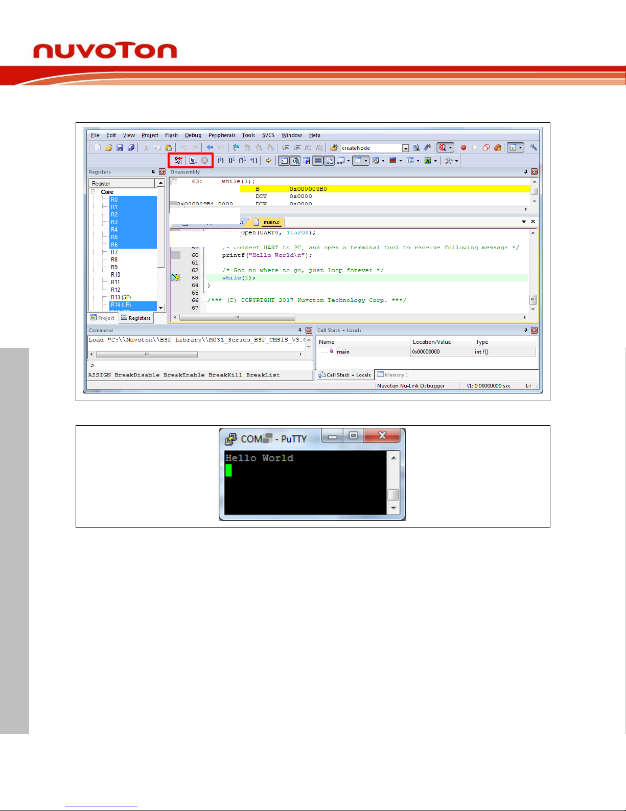
4. Figure 3-13 shows the debug mode under Keil MDK. Click “Run” and the debug message will be
printed out as shown in Figure 3-14. User can debug the project under debug mode by checking
Page 30
NuMaker-M032SE
Feb. 20, 2019 Page 30 of 37 Rev 1.00
NUMAKER-M032SE USER MANUAL
Maker Nu-mbed NUC472 User Manual
source code, assembly language, peripherals’ registers, and setting breakpoint, step run, value
monitor, etc.
2. Stop
3 1 2
1. Run
3. Reset
Figure 3-13 Keil MDK Debug Mode
Figure 3-14 Debug Message on Serial Port Terminal Windows
Page 31
NuMaker-M032SE
Feb. 20, 2019 Page 31 of 37 Rev 1.00
NUMAKER-M032SE USER MANUAL
Maker Nu-mbed NUC472 User Manual
3.6.2 IAR EWARM
This section provides steps to beginners on how to run a project by using IAR EWARM.
1. Double click the “Template.eww” to open the project.
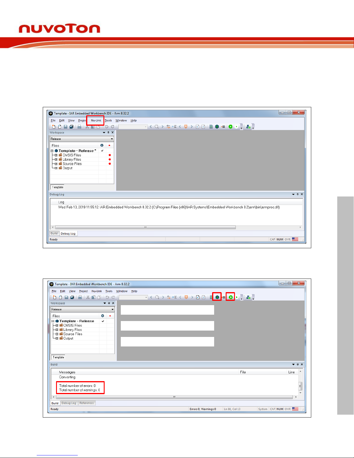
2. Make sure the toolbar contain “Nu-Link” item as shown in Figure 3-15.
Note: If the toolbar does not contain “Nu-Link” item, please rework section 3.2.
Figure 3-15 IAR EWARM Window
3. Make target file as presented in Figure 3-16. After successfully compile the project, download
code to the flash memory and enter debug mode.
1 3
2
1. Make
3. Download and Debug
2. Successfully compile
Figure 3-16 Compile and Download the Project
Page 32
NuMaker-M032SE
Feb. 20, 2019 Page 32 of 37 Rev 1.00
NUMAKER-M032SE USER MANUAL
Maker Nu-mbed NUC472 User Manual
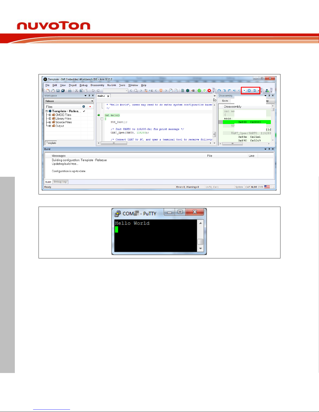
4. Figure 3-17 shows the debug mode under IAR EWARN. Click “Go” and the debug message will
be printed out as shown in Figure 3-18. User can debug the project under debug mode by
checking source code, assembly language, peripherals’ registers, and setting breakpoint, step run,
value monitor, etc.
1 2 3
1. Go
3. Reset
2. Break
Figure 3-17 IAR EWARM Debug Mode
Figure 3-18 Debug Message on Serial Port Terminal Windows
3.6.3 NuEclipse
For more information about how to use NuEclipse, please refer to the NuEclipse User Manual.
Page 33
NuMaker-M032SE
Feb. 20, 2019 Page 33 of 37 Rev 1.00
NUMAKER-M032SE USER MANUAL
Maker Nu-mbed NUC472 User Manual
4 NUMAKER-M032SE SCHEMATICS
Nu-Link2-Me 4.1
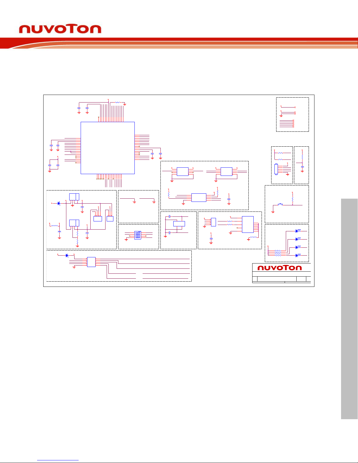
Figure 4-1 shows the Nu-Link2-Me circuit. The Nu-Link2-Me is a debugger and programmer that
supports on-line programming and debugging through SWD interface.
Figure 4-1 Nu-Link2-Me Circuit
GND
RED
GREEN
NULINK_I D1
NULINK_I D0
SWDH_CLK
ICEU1
<M48SSIDAE>
PB.61PB.52PB.43PB.34PB.25PB.16PB.07PA.118PA.109PA.910PA.811PF.612VBAT13PF.514PF.415PF.3
16
PF.2
17
PC.7
18
PC.6
19
PA.7
20
PA.6
21
VSS
22
VDD
23
LDO_CAP
24
PA.5
25
PA.4
26
PA.3
27
PA.2
28
PA.1
29
PA.0
30
VDDIO
31
nRESET
32
PF.033PF.1
34
PC.535PC.436PC.337PC.238PC.139PC.0
40
HSUSB_VRES
41
HSUSB_VDD33
42
HSUSB_VBUS
43
HSUSB_D-
44
HSUSB_VSS
45
HSUSB_D+
46
HSUSB_VDD12_C AP
47
HSUSB_ID
48
VSS
49
LDO_CAP
50
VDD
51
PC.14
52
PB.15
53
PB.14
54
PB.13
55
PB.12
56
AVDD
57
VREF
58
AVSS
59
PB.11
60
PB.10
61
PB.9
62
PB.8
63
PB.7
64
SWDH_DAT
ICELED
ICEVDD
SWDH_RST #
HXT_I
ICE_RST
ICEVDD
HXT_O
SWO
ICEC6
1u
C0603
ISPLED
KEY1
GND
ICEVDD
USB_HS_VBUS
USB_HS_CAP
USB_HS_REXT
GND
USB_HS_D+
USB_HS_D-
USB_HS_CAP
ICEC2
1u
C0603
ICE_DAT
ICE_CLK
SPIM_D3
SPIM_MISO0
SPIM_CS
SPIM_MOSI0
SPIM_CLK
SPIM_D2
GND
ICEVDD
USB_HS_VBUS
ICED3
0.1u
C0603
DEBUG RESET
ICEVDD
ICER3
10K
R0603
ICE_RST
ICEC9
1u
C0603
ICE_DAT
ICE_CLK
ICE_RST
ICE_DAT
ICEVDD
ICE_CLK
ICEJ1
HEADER_5(NC )
1
2
3
4
5
ICEVDD
ICER2
10K
R0603
ICER4
10K
R0603
ETMD1
ETMCK_MOSI
ETMD0_MISO
ETMD2_CK
ETMD3_SS
ICE_RXICE_RX_S
ICESW2
SMD HPS604-E
ICE_TXICE_TX_S
VCOM SWITCH
ETMD2_CK
ETMD3_SS
ETMCK_MOSI
ETMD0_MISO
NULINK_I D0 NULIN K_ID1
Nu-Trace, ID0 = 1, ID1 = 1
Nu-Link2, ID0 = 0, ID1 = 1
Nu-LInk2-Me, ID0 = 0, ID1 = 0
NULINK ID
SWDH_DAT
SWDH_CLK
SWDH_RST#
GND
TICEDAT
TICERST
MCUVCC_DI ODE
MCU_RX
MCU_TX
TICECLK
ICE_TX_S
ICE_RX_S
MCUVCC
1 2
ICED4
SS24A
ICER1
200 1%
R0603
HSUSB_VDD33
HXT_O
HXT_I
ICEC10 20p
C0603
ICEC11 20p
C0603
12M Crystal
ICEX1
12MHz SMD X3225B
1
XIN2GND
4
GND3XOUT
3.3V
SPIM_MISO0
ICEU2
W25Q16JVSSIQ
SOP8\5.23/1.27MM
CS#
1
DO
2
WP#
3
GND4DI
5
CLK
6
HOLD#
7
VCC
8
3.3V
SPI FLASH
ICEC12
0.1u
C0603
SN74LV2T45DCUR
ICEU4
SOP8/3.1/0.5
GND
4
A2
3
VCCA
1
DIR
5
A1
2
B2
6
B1
7
VCCB
8
SPIM_CLK_LV
SN74LV2T45DCUR
ICEU3
SOP8/3.1/0.5
GND
4
A2
3
VCCA
1
DIR
5
A1
2
B2
6
B1
7
VCCB
8
SPIM_MOSI0_LV
SPIM_CS_LV
SPIM_CS
ICEVDD
3.3V
SPIM_CS_LV SPIM_CLK
SPIM_MOSI0
SPIM_CLK_LV
SPIM_MOSI0_LV
ICEVDD
3.3V
ICER18
10K
R0603
3.3V
ICER19
10K
R0603
3.3V
ICE INTERFACE
ICEJ4
HEADER 2. 54 5X2 (NC)
1 2
3 4
5 6
7 8
9 10
Title
Size
File Name :
Rev
Date: Sheet
of
Author :
Nu-Link2-Me
1.0
Nu-Link2-Me
CMHuangA3
1 3Thursday, Janua ry 24, 2019
SWDH_DAT
SWDH_CLK
SWDH_RST#
SWO
ICE_RX_S
ICE_TX_S
ICEC7
4.7u
C0603
ICEC1
0.1u
C0603
ICEVDD
ICEC8
470p
C0603
MSG_EN
MSG_EN
ETMD3_SS I 2C1_SCL QSPI_SS BUSY
5V
ETMD2_CK I2C 1_SDA QSPI_C LK START
ETMCK_MOSIUART0_RX QSPI_MOSIPASSICE_RX
ETMD0_MISOUAR T0_TX QSPI_MISOFAILICE_TX
USB_HS_VBUS
ICEJ3
micro USB 5pin
MICRO_USB_AB
VBUS
1
D-
2
D+
3
GND
5
ID
4
Shield
6
Shield
7
Shield
8
Shield
9
Shield
10
Shield
11
DM
DP
ICEL2
FERRITE BEAD
L0603
ICER6
0
ICER7
0
USB_HS_DUSB_HS_D+
USB 2.0 HIGH SPEED DEVICES
ISPLED
RED
ICELED
GREEN
1 2
ICES3
0805 LED G (綠光)
普亮
KP-2012
DP
DM
ICERP1
8P4R-330
8P4RA
1 2
3 4
5 6
7 8
ICEJ2
HEADER04(NC )
1
2
3
4
ICEVDD
USB_HS_VBUS
1 2
ICES2
0805 LED R (紅光)
高亮
KP-2012
1 2
ICES1
0805 LED Y (黃光)
高亮
KP-2012
1 2
ICES0
0805 LED R (紅光)
高亮
KP-2012
LED
KEY1
ICEVDD
KEY
ICER5
10K
R0603
ICESW1
3x6x5 2PIN SMD
SW-2P-SMD
MCUVCC_DI ODE
MCUVCC_DI ODE
3.3V
ICE5V
ICE5V
ICEVDD
5V
ICE5V
USB_HS_VBUS
Power Switch
1 2
ICED1
SS24A
ICEUP2
ACE1117_ADJ
IN3ADJ1OUT2OUT
4
ICEUP1
AMS1117_3.3v
IN3GND1OUT2OUT
4
ICER8
120,1%
R0603
ICER9
82, 1%
R0603
3.3V
ICEVCC
ICEJPR2
1&2 (0 ohm)
123
1.8V 3.3V 3.3V
ICECT1
10uF/10V
TANT-A
12
1.8V
MCUVCC
ICEJPR1
1&2 (0 ohm)
123
4
1.8V
ICECT3
10uF/10V
12
ICEC5
0.1u
C0603
ICEVCC ICEVD D
ICEL1
FERRITE BEAD
ICECT2
10uF/10V
TANT-A
12
Off-page Connector
ICEC3
1u
C0603
ICEC4
0.1u
C0603
Page 34
NuMaker-M032SE
Feb. 20, 2019 Page 34 of 37 Rev 1.00
NUMAKER-M032SE USER MANUAL
Maker Nu-mbed NUC472 User Manual
M032 platform 4.2
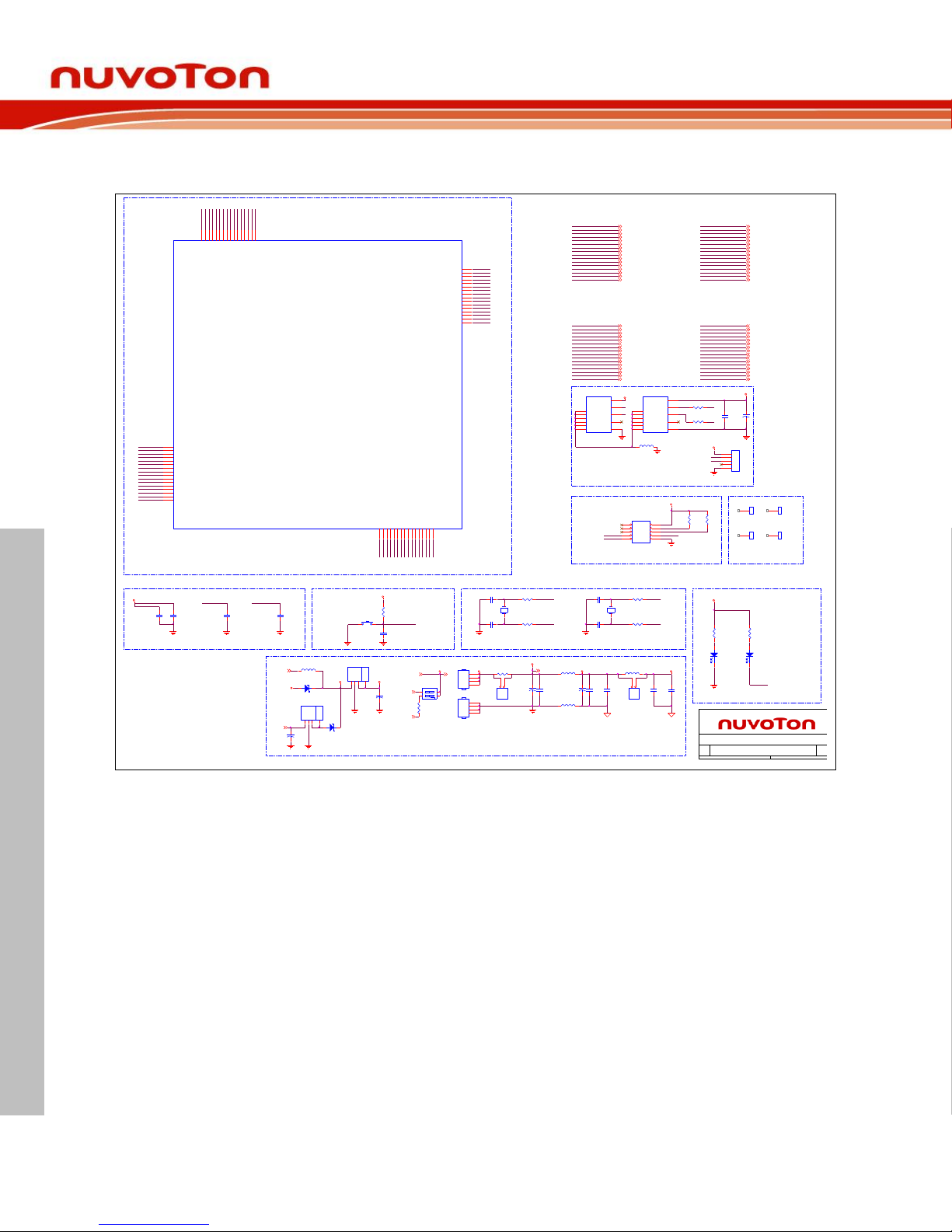
Figure 4-2 shows the M032 platform circuit.
Figure 4-2 M032 platform Circuit
P15P9P12
P16
P13
P14
P8P5P6P7P11
P10P1P3P2P4
PD2
PD0
PC0_NU4_SDA
PC1_NU4_SCL
J1
HEADER 2.54 5X2 (NC )
1 2
3 4
5 6
7 8
9 10
USB_VBUS
PD3
PD1
TICEDAT
TICECLK
USB_D-
PB12_RXD0
PB13_TXD0
ICE
USB_D+
USB_VDD33_CAP
P42
P37
P38
P44
P43
P39
P40
P41
SW1
3x6x5 2PIN SMD
SW-2P-SMD
P45
C9
10u
C0603
R3
10KR
R0603
P48 USB_VDD33_CAP
P46
P47
RESET
VDD
nRESET
P36
P35
P33 PF0_ICE_DAT
P34 PF1_ICE_CLK
H1
H-3.4X6(NC)
1
H4
H-3.4X6(NC)
1
H3
H-3.4X6(NC)
1
H2
H-3.4X6(NC)
1
Mounting Hole
PB7_NU2_A0
PB8
PB9
PB14_LED_R
PB11
VDD_MCU
LDO_CAP
GND
AVSS
VREF
AVDD
PB10
MCU_TX
MCU_RX
PB15_NU5_GPIO
PC14
P50 LDO_C AP
P49
P54 PB14_LED_R
P53
P58
P57
P52
P51 VDD _2
P56 PB12_RXD0
P55 PB13_TXD0
P59
P60
P61
P63
P62
P64
P20
P19
P18
P17
P22
P21
P25
P24
P23
P28
P27
P26
P32
P31
P30
P29
12
LEDG1
Green
LED0805
PB6_NU2_A1
PB2_NU3_D0/RX
PB3_NU3_D1/TX
PB4_NU2_A3
PB5_NU2_A2
PA10_NU5_MOSI
PA11_NU5_CLK
PB0_NU2_A4/SDA/RX
PB1_NU2_A5/SCL/TX
PF4_X32_OUT
PF5_X32_IN
PF14
PA9_NU5_MISO
PF6
PA8_NU5_SS
PF3_XT1_IN
P35
P34
P33
P37
P36
P42
P41
P40
P39
P38
P46
P45
P44
P43
P47
P48
GND
PC6
PC7
PF2_XT1_OUT
PA2_NU3_D13/CLK
PD15
PA0_NU3_D11/MOSI
VDDIO
PA1_NU3_D12/MISO
PA3_NU3_D10/SS
VDD_MCU
TICERST
P50
P49
nRESET
PF1_ICE_CLK
PF0_ICE_DAT
P52
P51
R14
100KR
R0603
VDD
P56
P55
P54
P53
R13
100KR
R0603
P60
P59
P58
P57
P62
P61
P64
P63
Title
Size Doc ument Number Rev
Date: Sheet of
NuMaker-PFM-M032SE
v1.3
M032SE3AE
Custom
2 3Friday, February 01, 2019
Bypass Cap
P33 - P48
P17 - P32
P1 - P16
P49 - P64
R7
330R
R0603
C4
0.1u
C0603
C3
0.1u
C0603
C5
1u
C0603
R6
330R
R0603
12
LEDR1
Red
LED0805
VDDVDD_MCU
P21
P22
P17 PF2_XT1_OUT
P18
P25
P24
P23 VDD_1
P19
P20
P30
P29
P28
P26
P27
P32 nRESET
P31 VDDIO
PA5_NU3_D8
PA7_NU3_D6
PA6_NU3_D7
PA4_NU3_D9
PC2_NU3_D5
PC4_NU3_D2
PC5_NU3_D3
PC3_NU3_D4
P2
P1
P6
P5
P4
P3
P7
P8
P9
P11
P10
P12
P13
P14 PF5_X32_IN
P15 PF4_X32_OUT
P16 PF3_XT1_IN
L5
FERRITE BEAD
C15
1u
C0603
U1
<M032SE3AE>
PB.6/ADC0_CH 6/EBI_nWRH/U ART1_RXD/EBI _nCS1/PWM1_BRAKE1/ PWM1_CH5/I NT4/ACMP1_O1PB.5/ADC0_CH 5/ACMP1_N/I2C 0_SCL/PWM0_CH 0/UART2_TXD /TM0/IN T02PB.4/ADC0_CH 4/ACMP1_P1/I2C0_SD A/PWM0_CH1/ UART2_RXD/ TM1/INT 13PB.3/ADC0_CH 3/ACMP0_N/I2C 1_SCL/UART1_T XD/PWM0_CH 2/PWM0_BRAKE0/T M2/INT24PB.2/ADC0_CH 2/ACMP0_P1/I2C1_SD A/UART1_RXD /PWM0_CH3/ TM3/INT 35PB.1/ADC0_CH 1/UART2_TXD/ I2C1_SCL/PWM 0_CH4/PWM1_C H4/PWM0_BRAKE06PB.0/ADC0_CH 0/UART2_RXD/ SPI0_I2SMCLK/I 2C1_SDA/PWM0_C H5/PWM1_CH 5/PWM0_BRAKE17PA.11/ACMP0_P0/EBI_nR D/USCI0_C LK/TM0_EXT8PA.10/ACMP1_P0/EBI_nW R/USCI0_D AT0/TM1_EXT9PA.9/EBI_MCLK/ USCI0_DAT1/U ART1_TXD/T M2_EXT10PA.8/EBI_ALE/USC I0_CTL1/UART 1_RXD/TM3_EXT /INT411PF.6/EBI_ADR 19/SPI0_MOSI/EBI_nC S012PF.14/PWM1_BR AKE0/PWM0_BRAKE0/PWM 0_CH4/CLKO/T M3/INT513PF.5/UART 2_RXD/UART2_nC TS/PWM0_CH 0/X32_IN/ADC 0_ST14PF.4/UART 2_TXD/UART2_nR TS/PWM0_CH 1/X32_OUT15PF.3/EBI_nCS0/ UART0_TXD/I 2C0_SCL/XT1_IN
16
PF.2/EBI_nCS1/U ART0_RXD/I2C0_SDA/XT1_OUT
17
PC.7/EBI_AD9/U ART0_nCTS/PWM1_CH2/TM0/INT3
18
PC.6/EBI_AD8/U ART0_nRTS/PWM1_CH3/TM1/INT2
19
PA.7/EBI_AD7/U ART0_TXD/I2C1_SCL/PWM1_CH4/AC MP0_WLAT/TM2/INT1
20
PA.6/EBI_AD6/U ART0_RXD/I2C1_SDA/PWM1_CH 5/ACMP1_WLAT/TM3/INT0
21
VSS
22
VDD
23
PD.15/PWM0_CH5/TM3/IN T1
24
PA.5/UART0_nCTS/UART0_TXD/I2C0_SC L/PWM0_CH0
25
PA.4/SPI0_I2SMCLK/UAR T0_nRTS/UART0_RXD/I2C0_SDA/ PWM0_CH1
26
PA.3/SPI0_SS/UART1_TXD/I2C1_SC L/PWM0_CH2/CLKO/ PWM1_BRAKE1
27
PA.2/SPI0_CLK/U ART1_RXD/I2C1_SDA/PWM0_CH 3
28
PA.1/SPI0_MISO/UART0_TXD/UART1_nCTS/PW M0_CH4
29
PA.0/SPI0_MOSI/UART0_RXD/U ART1_nRTS/PWM0_CH5
30
PF.15/PWM0_BRAKE0/PWM0_CH 1/TM2/CLKO/INT4
31
nRESET
32
PF.0/ICE_D AT
33
PF.1/ICE_C LK
34
PC.5/EBI_AD5/ UART2_TXD/I 2C1_SCL/PWM1_C H0
35
PC.4/EBI_AD4/ UART2_RXD/I 2C1_SDA/PWM1_C H1
36
PC.3/EBI_AD3/ UART2_nRTS/PW M1_CH237PC.2/EBI_AD2/ UART2_nCTS/PW M1_CH3
38
PC.1/EBI_AD1/ UART2_TXD/I 2C0_SCL/PWM1_C H4/ACMP0_O
39
PC.0/EBI_AD0/ UART2_RXD/I 2C0_SDA/PWM1_C H5/ACMP1_O
40
PD.3/EBI_AD10/U SCI0_CTL1/SPI 0_SS/UART0_TXD
41
PD.2/EBI_AD11/U SCI0_DAT1/SPI 0_CLK/UART0_R XD
42
PD.1/EBI_AD12/U SCI0_DAT0/SPI 0_MISO
43
PD.0/EBI_AD13/U SCI0_CLK/SPI0_M OSI/TM2
44
USB_VBUS
45
USB_D-
46
USB_D+
47
USB_VDD33_CAP
48
VSS
49
LDO_CAP
50
VDD
51
PC.14/EBI_AD11/SPI 0_I2SMCLK/USCI0_C TL0/TM1
52
PB.15/ADC0_CH 15/EBI_AD12/SPI0_SS/U SCI0_CTL1/UART0_nCTS/PW M1_CH0/TM0_EXT/PWM0_BRAKE1
53
PB.14/ADC0_CH 14/EBI_AD13/SPI0_CLK/ USCI0_DAT1/UAR T0_nRTS/PWM1_CH1/TM1_EXT/CLKO
54
PB.13/ADC0_CH 13/ACMP0_P3/ACMP1_P3/EBI_AD14/SPI 0_MISO/USCI0_DAT0/U ART0_TXD/PWM1_CH2/TM2_EXT
55
PB.12/ADC0_CH 12/ACMP0_P2/ACMP1_P2/EBI_AD15/SPI 0_MOSI/USCI0_CLK/ UART0_RXD/PWM1_CH3/TM3_EXT
56
AVDD
57
VREF
58
AVSS
59
PB.11/ADC0_CH 11/EBI_ADR16/UAR T0_nCTS/I2C1_SCL/SPI0_I 2SMCLK
60
PB.10/ADC0_CH 10/EBI_ADR17/UAR T0_nRTS/I2C1_SDA
61
PB.9/ADC0_CH 9/EBI_ADR18/UAR T0_TXD/UART1_nCTS
62
PB.8/ADC0_CH 8/EBI_ADR19/UAR T0_RXD/UART1_nRTS
63
PB.7/ADC0_CH 7/EBI_nWRL/UAR T1_TXD/EBI_nCS0/PWM1_BRAKE0/PWM1_CH4/ INT5/ACMP0_O
64
ADAVSS
PF2_XT1_OUT
PF3_XT1_IN
R2 0
R5 0
X1
32MHz 49S SMD
XTAL\LP\SMD
C8 20p
C2 20p
HXT & LXT Crystal
X2
SMD 32.768K X3215
9HT9
PF4_X32_OUT
PF5_X32_IN
R1 0
R4 0
C1 20p
C7 20p
C12
0.1u
C14
0.1u
AVDD VREF
VREF1
NC
1
2
CT3
10uF/10V
12
L2
FERRITE BEAD
L4
FERRITE BEAD
ADAVSS
C13
0.01u
LED
VDD_MCU
VDD
SW2
SMD HPS602-E
NU1_VIN
USB_VDD33_CAP
PB14_LED_R
UP2
AMS1117_5v
IN3GND1OUT2OUT
4
1 2
D2
SS24A
VDD
CT5
10uF/10V
TANT-A
12
VDD_MCU
1 2
D1
SS24A
NU1_3VCC
UP1
AMS1117_3.3v
IN3GND1OUT2OUT
4
CT4
10uF/10V
TANT-A
12
NU1_5VCC
R16 0
MCUVCC_DIOD E
AMMETER
NC
1
2
JP2
NC
1
2
3
4
JP1
NC
1
2
3
4
C11
0.1u
VDD
CT2
10uF/10V
12
L1
FERRITE BEAD
Power
ICE5V
NU1_5VCC
NU1_3VCC
USB_VBUS
R12 0(NC)
C6
1u
C0603
LDO_CAP
VDD_2
VDD_1
D-
USB_VBUS
D+
J3
NC
1
2
3
4
5
USB Device
HJ2
micro USB 5pin
MICRO_USB_B
VBUS
1
D-
2
D+
3
GND
5
ID
4
Shield
6
Shield
7
Shield
8
Shield
9
Shield
10
Shield
11
USB_VBUS
D+
D-
D+
D- USB_D-
USB_D+
C10
0.1u
R927
R1127
CT1
1uF/16V
12
L3
FERRITE BEAD
L0603
USB_VBUS
J2
micro USB 5pin
MICRO_USB_AB
VBUS
1
D-
2
D+
3
GND
5
ID
4
Shield
6
Shield
7
Shield
8
Shield
9
Shield
10
Shield
11
Page 35
NuMaker-M032SE
Feb. 20, 2019 Page 35 of 37 Rev 1.00
NUMAKER-M032SE USER MANUAL
Maker Nu-mbed NUC472 User Manual
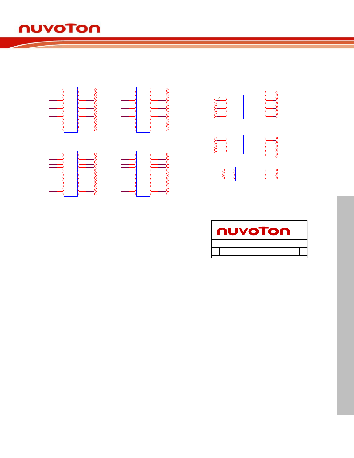
Extension Connector 4.3
Figure 4-3 shows extension connectors of NuMaker-M032SE.
Figure 4-3 Extension Connectors Circuit
PB6_NU2_A1
PB2_NU3_D0/RX
PB3_NU3_D1/TX
PB4_NU2_A3
PB5_NU2_A2
PA10_NU5_MOSI
PA11_NU5_CLK
PB0_NU2_A4/SDA/RX
PB1_NU2_A5/SCL/TX
PF4_X32_OUT
PF5_X32_IN
PF14
PA9_NU5_MISO
PF6
PA8_NU5_SS
PF3_XT1_IN
P1
P6
P5
P4
P3
P2
P11
P10
P9
P8
P7
P16
P15
P14
P13
P12
PF2_XT1_OUT
GND
PD15
PC6
PC7
PA3_NU3_D10/SS
PA2_NU3_D13/CLK
TICERST
PA0_NU3_D11/MOSI
VDDIO
PA1_NU3_D12/MISO
VDD_MCU
P17
P18
P23
P19
P20
P21
P22
P28
P26
P27
P25
P24
P32
P31
P30
P29
P17
P18
P23
P19
P20
P21
P22
P29
P28
P26
P27
P25
P24
P32
P31
P30
P33 - P48
JP4
HEADER 2.54 16X2 (NC)
1 2
3 4
5 6
7 8
9 10
11 12
13 14
15 16
17 18
19 20
21 22
23 24
25 26
27 28
29 30
31 32
P37
P38
P43
P39
P40
P41
P42
P47
P45
P44
P48
P46
P36
P35
P34
P33
P37
P38
P43
P39
P40
P41
P42
P48
P46
P47
P45
P44
P33
P34
P36
P35
JP6
HEADER 2.54 16X2 (NC)
1 2
3 4
5 6
7 8
9 10
11 12
13 14
15 16
17 18
19 20
21 22
23 24
25 26
27 28
29 30
31 32
P49 - P64
PA5_NU3_D8
PA4_NU3_D9
PC3_NU3_D4
PA6_NU3_D7
PA7_NU3_D6
PC4_NU3_D2
PC5_NU3_D3
PC2_NU3_D5
PB9
LDO_CAP
GND
PB7_NU2_A0
PB8
PC5_NU3_D3
PC3_NU3_D4
PC2_NU3_D5
AVDD
PB10
PB11
VDD_MCU
PC4_NU3_D2
PC14
AVSS
VREF
P50
P49
MCU_TX
MCU_RX
PB15_NU5_GPIO
P51
PB14_LED_R
P53
P58
P57
P52
PA5_NU3_D8
PA4_NU3_D9
PA7_NU3_D6
P56
P55
P59
P60
P54
PA6_NU3_D7
P61
P63
P62
P64
External Connector
P50
P53
P58
P57
P52
P51
P49
P56
P55
P59
P60
P54
P61
P63
P62
P64
UNO Interface
P1 - P16
P17 - P32
P2
P4
P3
P1
P12
P11
P10
P9
P8
P7
P6
P5
P16
P15
P14
P13
JP3
HEADER 2.54 16X2 (NC)
1 2
3 4
5 6
7 8
9 10
11 12
13 14
15 16
17 18
19 20
21 22
23 24
25 26
27 28
29 30
31 32
JP5
HEADER 2.54 16X2 (NC)
1 2
3 4
5 6
7 8
9 10
11 12
13 14
15 16
17 18
19 20
21 22
23 24
25 26
27 28
29 30
31 32
Title
Size Document Number Rev
Date: Sheet of
NuMaker-PFM-M032SE
v1.3
Ext. Connector
Custom
3 3Monday, January 28, 2019
PC0_NU4_SDA
PC1_NU4_SCL
NU5
header 2.54 2X4 公(正面)
SPI0_MISO1VCC
2
SPI0_CLK3SPI0_MOSI
4
RESET
5
GND
6
SPI0_SS7GPIO
8
PD3
PD1
PD2
PD0
NU1
HEADER 2.54 8X1 f emale
NC
1
VDD
2
MCU_RESET
3
3VCC
4
5VCC
5
VSS
6
VSS
7
VIN
8
TICECLK
USB_D-
USB_VBUS
NU3
HEADER 2.54 8X1 f emale
D0
1
D1
2
D2
3
D3
4
D4
5
D5
6
D6
7
D7
8
USB_D+
USB_VDD33_CAP
TICEDAT
NU2
HEADER 2.54 6X1 f emale
A0
1
A1
2
A2
3
A3
4
A4/SDA
5
A5/SCL
6
NU4
HEADER 2.54 10X1 f emale
D8
1
D9
2
D10
3
D11
4
D12
5
D13
6
VSS
7
VREF
8
I2C_SDA
9
I2C_SCL
10
GND
GND
TICERST
VDD
PB4_NU2_A3
PB6_NU2_A1
PB5_NU2_A2
PB7_NU2_A0
PC0_NU4_SDA
PC1_NU4_SCL
PB0_NU2_A4/SDA/RX
PB1_NU2_A5/SCL/TX
PA3_NU3_D10/SS
PA2_NU3_D13/CLK
VREF
GND
PA0_NU3_D11/MOSI
PA1_NU3_D12/MISO
PB2_NU3_D0/RX
PB3_NU3_D1/TX
PA11_NU5_CLK
PA8_NU5_SS
PA9_NU5_MISO
TICERST
PB15_NU5_GPIO
GND
PA10_NU5_MOSI
VDD
NU1_VIN
NU1_5VCC
NU1_3VCC
Page 36

NuMaker-M032SE
Feb. 20, 2019 Page 36 of 37 Rev 1.00
NUMAKER-M032SE USER MANUAL
Maker Nu-mbed NUC472 User Manual
5 REVISION HISTORY
Date
Revision
Description
2019.02.20
1.00
1. Initially issued.
Page 37
NuMaker-M032SE
Feb. 20, 2019 Page 37 of 37 Rev 1.00
NUMAKER-M032SE USER MANUAL
Maker Nu-mbed NUC472 User Manual
Important Notice
Nuvoton Products are neither intended nor warranted for usage in systems or equipment, any
malfunction or failure of which may cause loss of human life, bodily injury or severe property
damage. Such applications are deemed, “Insecure Usage”.
Insecure usage includes, but is not limited to: equipment for surgical implementation, atomic
energy control instruments, airplane or spaceship instruments, the control or operation of
dynamic, brake or safety systems designed for vehicular use, traffic signal instruments, all
types of safety devices, and other applications intended to support or sustain life.
All Insecure Usage shall be made at customer’s risk, and in the event that third parties lay
claims to Nuvoton as a result of customer’s Insecure Usage, customer shall indemnify the
damages and liabilities thus incurred by Nuvoton.
 Loading...