


ENGLISH |
|
|
|
|
|
|||
Danger |
|
|
|
|
1. |
|||
Exposure to extremely high noise levels may cause a permanent |
|
|||||||
hearing loss. Individuals vary considerably to noise induced hearing |
2. |
|||||||
loss but nearly everyone will lose some hearing if exposed to sufficiently |
|
|||||||
intense noise for a sufficient time. The U.S. Government's |
3. |
|||||||
Occupational Safety and Health Administration (OSHA) has specified |
|
|||||||
the following permissible noise level exposures: |
|
|
|
4 . |
||||
|
|
|
|
|
|
|
|
5. |
|
DURATION PER DAY (HOURS) |
8 6 |
4 3 2 1 |
|
6. |
|||
|
SOUND LEVEL (dB) |
90 93 |
95 97 100 103 |
|
||||
|
|
7. |
||||||
|
|
|
|
|
|
|
8. |
|
According to OSHA, any exposure in the above permissible limits could |
||||||||
result in some hearing loss. Ear plugs or protectors in the ear canal or over |
|
|||||||
the ears must be worn when operating this amplification system in order to |
9. |
|||||||
prevent a permanent hearing loss. If exposure in excess of the limits as |
||||||||
put forth above, to insure against potentially harmful exposure to high |
|
|||||||
sound pressure levels, it is recommended that all persons exposed to |
|
|||||||
equipment capable of inducing high sound pressure levels, such as this |
|
|||||||
amplification system, be protected by hearing protectors while this unit is in |
|
|||||||
operation. |
|
|
|
|
10. |
|||
|
|
|
|
|
|
|
|
|
|
|
|
|
|
|
|
|
|
|
|
|
CAUTION |
|
|
|
|
|
|
|
|
RISK OF ELECTRIC SHOCK |
|
|
|
|
|
|
|
|
DO NOT OPEN |
|
|
|
|
|
|
|
|
|
|
|
|
|
11 . |
|
|
CAUTION: TO REDUCE THE RISK OF ELECTRIC SHOCK, DO |
|
|
||||
|
|
|
12. |
|||||
|
|
NOT REMOVE CHASSIS. NO USER-SERVICEABLE |
|
|||||
|
|
PARTS INSIDE. REFER SERVICING TO QUALIFIED |
|
|
||||
|
|
SERVICE PERSONNEL. |
|
|
|
|
|
|
|
|
|
|
|
||||
|
|
AVIS: RISQUE DE CHOC ELECTRIQUE-NE PAS OUVRIR. |
13. |
|||||
|
|
|
|
|
|
|
|
|
THIS SYMBOL IS INTENDED TO ALERT THE USER TO THE PRESENCE
OF NON-INSULATED "DANGEROUS VOLTAGE" WITHIN THE 14.
PRODUCT'S ENCLOSURE THAT MAY BE OF SUFFICIENT MAGNITUDE
TO CONSTITUTE A RISK OF ELECTRIC SHOCK TO PERSONS.
15.
THIS SYMBOL IS INTENDED TO ALERT THE USER TO THE PRESENCE
OF IMPORTANT OPERATING AND MAINTENANCE (SERVICING)
INSTRUCTIONS IN THE LITERATURE ACCOMPANYING THE UNIT.
APPARATUS SHALL NOT BE EXPOSED TO DRIPPING OR SPLASHING |
16. |
|
AND THAT NO OBJECTS FILLED WITH LIQUIDS, SUCH AS VASES, |
||
|
||
SHALL BE PLACED ON THE APPARATUS. |
|
Page 1
IMPORTANT SAFETY INSTRUCTIONS
Read all safety and operating instructions before using this product.
All safety and operating instructions should be kept for future reference.
Read and understand all warnings listed on the operating instructions.
Follow all operating instructions to operate this product. This product should not be used near water, i.e. Bathtub, sink,swimming pool, wet basement, etc.
Only use dry cloth to clean this product.
Do not block any ventilation openings, It should not be placed flat against a wall or placed in a built-in enclosure that will impede the flow of cooling air.
Do not install this product near any heat sources ;such as,radiators, heat registers, stove or other apparatus (including heat producing amplifiers) that produce heat.
Do not defeat the safety purpose of the polarized or groundingtype plug. A polarized plug has two blades with one wider than the 0ther.A grounding-type plug has two blades and a third grounding prong. The wide blade or the third prong are provided for your safety If the provided plug does not fit into your outlet, consult an electrician for replacement of the obsolete outlet.
Protect the power cord being walked on or pinched, particularly at Plugs, convenience receptacles and the point where they exit from the apparatus. Do not break the ground pin of the power supply cord.
Only use attachments specified by the manufacturer.
Use only with the cart, stand, tripod, bracket, or table specified by the manufacturer or sold with the apparatus. When a cart is used, use caution when moving cart/apparatus combination to avoid injury from tip-over.
Unplug this apparatus during lightning storms or when unused for long periods of time.
Care should be taken so that objects do not fall and liquids are not spilled into the unit through the ventilation ports or any other openings.
Refer all servicing to qualified service personnel. Servicing is required when the apparatus has been damaged in any way; such as, power-supply cord or plug is damaged, liquid has been spilled or objects have fallen into the apparatus, the apparatus has been exposed to rain or moisture, does not operate normally or has been dropped.
WARNING: To reduce the risk of fire or electric shock, do not expose this apparatus to rain or moisture.
FRENCH
Danger
L‘exposition a des niveaux eleves de bruit peut provoquer une perte permanente de l’audition, Chaque organisme humain reagit differemment quant a la perte de l’audition, mais quasiment tout le monde subit une diminution de I’acuite auditive lors d’une exposition suffisamment longue au bruit intense. Les autorites competentes en reglementation de bruit ont defini les expositions tolerees aux niveaux de bruits:
DURE EN HEURES PAR JOUR |
8 6 |
4 3 2 |
1 |
INIVEAU SONORE CONTINU EN dB |
90 93 |
95 97 100 |
103 |
Selon les autorites, toute exposition dans les limites citees ci-dessus, peuvent provoquer certaines pertes d’audition. Des bouchons ou protections dans l’appareil auditif ou sur l’oreille doivent etre portes lors de l’utilisation de ce systeme d’amplification afin de prevenir le risque de perte permanente de l’audition, Dans le cas d’expositions superieures aux limites precitees il est recommande, afin de se premunir contre les expositions aux pressions acoustiquese I evees potentielIement dangeure u ses, aux personnes exposees aux equipements capables de delivrer de telles puissances, tels ce systeme d’amplification en fonctionnement, de proteger l’appareil auditif.
ATTENTION
RISQUE DE CHOC ELECTRIQUE
NE PAS OUVRIR.
ATTENTION: AFIN DE LlMlTER LE RISQUE DE CHO ELECTR/QUE, NE
PAS ENLEVER LE CHASSIS. NE CONTIENT PAS DE
PIECES POUVANT ETRE REPAREE PAR L’UTILISATEUR.
CONFER LE SERVICE APRES-VENTE AUX
REPARATEURS
CE SYMBOLE A POUR BUT D'AVERTIR L'UTILISATEUR DE LA PRESENCE DE VOLTAGE DANGEREUX NON-ISOLE A L'INTERIEUR DE CE PRODUIT QUI PEUT ETRE DE PUISSANCE SUFFISAMMENT IMPORTANTE POUR PROVOQUER UN CHOC ELECTRIQUE AUX PERSONNES.
CE SYMBOLE A POUR BUT D'AVERTIR L'UTILISATEUR DE LA PRESENCE
D'INSTRUCTIONS D'UTILISATION ET DE MAINTENANCE DANS LES
DOCUMENTS FOURNIS AVEC CE PRODUIT.
AFIN DE REDUIRE LES RISQUÉ D'INCENDIE ET DE DECHARGE
ELECTRIQUE, NE PAS EXPOSER CET APPAREIL A LA PLUIE OU A
L'HUMIDITE.
Page 2
IMPORTANTES INSTRUCTIONS DE SECURITE
1.Lire avec attention toutes les recommandations et précautions d'emploi avant d'utiliser ce produit.
2.Toutes les recommandations et précautions d'emploi doivent être conservées afin de pouvoir s'y reporter si nécessaire.
3.Lire et comprendre tous les avertissements énumérés dans les précautions d'emploi.
4.Suivre toutes les précautions d'emploi pour utiliser ce produit.
5.Ce produit ne doit pas être utilisé près d'eau, comme par exemple baignoires, éviers, piscine, sous-sol humides ... Etc.
6.Utiliser exclusivement un chiffon sec pour nettoyer ce produit.
7.Ne bloquér aucune ouverture de ventilation. Ne pas placer le produit tout contre un mur ou dans une enceinte fernée, cela gênerait le flux d'air nécessaire au refroidissement.
8.Ne pas placer le produit près de toute source de chaeur telle que radiateurs, arrivées d'air chaud, fourneaux ou autres appareils générant de la chaleur (incluant les amplificateurs producteurs de chaleur) .
9.Ne pas négliger la sécurité que procure un branchement polarisé ou avec raccordement à la terre, Un branchement polarisé comprend deux fiches dont l'une est plus large que l'autre. Un branchement à la terre comprend deux fiches plus une troisième reliée à la terre. Si la fiche secteur fournie ne s'insert pas dans votre prise de courant. consulter un 'électricien afin de remplacer votre prise obsolète.
10.Protéger le cordon d'alimentation de tout écrasement ou pincement, particulièrement au niveau des fiches, des réceptacles utilisés et à l'endroit de sortie de l'appareil. Ne pas casser la fiche de terre du cordon d'alimentation.
11.Utiliser uniquement les accessoires spécifiés par le constructeur.
12.Utiliser uniquement avec le chariot de transport, le support, le trépied, la console ou la table spécifiés par le constructeur ou vendus avec l'appareil. Lors de l'utilisation d'un chariot, bouger avec précaution l'ensemble chariotlappareil afin d'éviter les dommages d'un renversement.
13Débrancher cet appareil lors d'orages ou s'il n'est pas utilisé pendant une longue période.
14.Des précautions doivent être prises afin qu'aucun objet ne tombe et qu'aucun liquide ne se répande à l'intérieur de l'appareil par les orifics de ventilation ou n'importe quelle autre ouverture.
15.Pour toutes interventions techniques s'adresser à un technicien qualifié.L'intervention technique est nécessaire lorsque l'appareil a été endommagé de n'importe quelle façon, comme par exemple si le cordon secteur ou sa fiche sont détériorés,si du liquide a coulé ou si des objets sont tombés à l'intérieur de l'apparei1,si l'appareil a été exposé à la pluie ou à l'humidité, s'il ne fonctionne pas normalement ou s'il est tombé.
16.ATTENTI0N:Pour réduire le risque d'incendie ou de choc electrique ne pas exposer l'appareil à la pluie ou à l'humidité.
|
ANTENNA |
|
LEAD-IN |
|
WIRE |
GROUND |
|
CLAMPS |
|
|
ANTENNA |
|
DISCHARGE UNIT |
|
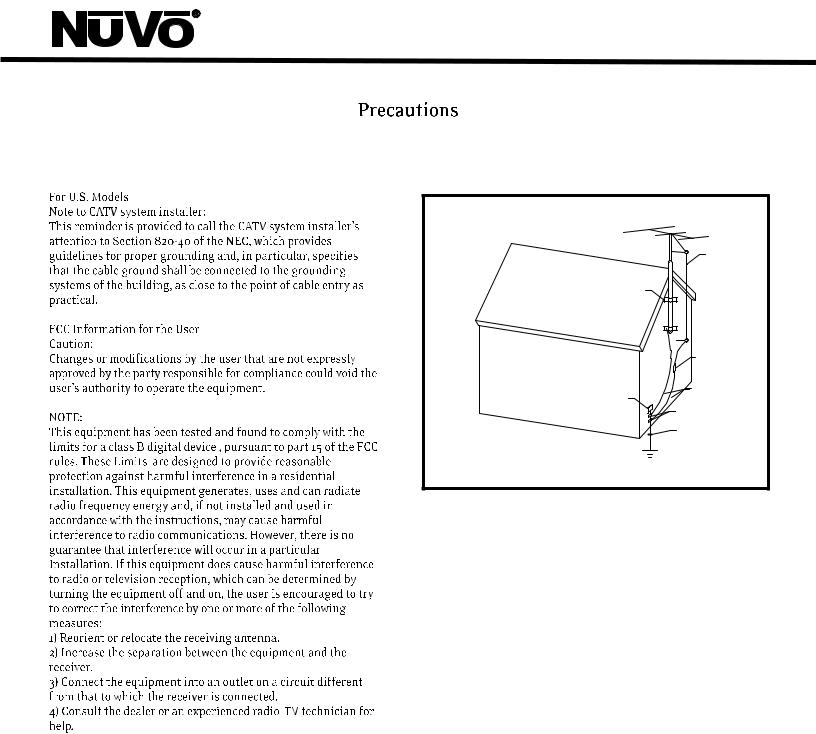
NEC SECTION |
|
810-20 |
ELECTRIC |
GROUNDING |
SERVICE |
CONDUCTORS |
ENTRANCE |
GROUND CLAMPS |
|
POWER SERVICE |
|
GROUPING ELECTRODE |
NEC NATIONAL ELECTRICAL CODE |
SYSTEM NEC ART 250 |
PART H |
Page 3

Introduction
Congratulations on your purchase of the NuVo T2 dual Tuner. With the T2 Dual Tuner, broadcast music enters the twenty-first century. Finally you can enjoy state-of-the-art, advanced radio and satellite receiver technology, with astonishingly clear reception throughout the entire home.
Combined with the NuVo Concerto Whole Home Audio Distribution System, the T2 gives you the ultimate radio experience with Radio Data Service. RDS displays artist and song information on the Concerto Display Pads, which means no more waiting to hear a song title, only to be disappointed when the station cuts to a commercial. Interference Adaptive Signal Processing (IASP) circuitry combined with NuVo’s patent pending Remote Active Antenna provide remarkable radio reception, even when radio stations are typically difficult to receive. The T2 XM satellite tuner provides the full range of stations direct into your home. Listening selections are streamed in real time to all the Display Pads throughout the NuVo Concerto System. The included XM antenna makes satellite reception for the home easy and reliable.
The T2 is packed with many powerful features, and is designed to integrate seamlessly with any distributed audio system. This manual is a guide to making the installation complete, and for making the most of your T2 Tuner. When properly installed, the T2 will provide years of listening enjoyment.
Table of Contents:
Basic Features
Front Panel |
page 6 |
Back Panel |
page 7 |
RC3 Remote Control |
page 8 |
I. Installing the NV-T2 Dual Tuner
Stereo Audio Conncetions |
page 9 |
Direct IR Control |
page 9 |
IR Pass-Thru |
page 10 |
AM/FM and XM Antenna Input |
page 11 |
Proper Location of the XM Antenna |
page 12 |
Subscribing to the XM Service |
page 12 |
II. Front Panel Menu Controls AM/FM
Exit Menu |
page 13 |
Force Mono |
page 13 |
Brightness |
page 13 |
Advanced Settings
Operating Mode |
page 14 |
Regional Setup |
page 14 |
Fine-Tuning |
page 14 |
Seek Threshold |
page 14 |
Audio Settings |
page 15 |
Auto-On |
page 15 |
AUX Input |
page 16 |
Noise Blanking |
page 16 |
Rs232 Communication |
page 16 |
III. Front Panel Menu Control XM
Signal Status |
page 17 |
Info |
page 17 |
Advanced Settings |
page 17 |
Diagnostics |
page 17 |
XM Display Button |
page 17 |
IV. Stand-alone Front Panel Use of the T2
Tuning a Desired Station
Step Tune Mode |
page 18 |
Seek Tune Mode |
page 18 |
Scan Tune Mode |
page 18 |
Direct Numeric Tuning |
page 18 |
Radio Data Service |
page 18 |
Signal Strength/Stereo Indicator |
page 19 |
Using the Memory Feature |
page 19 |
Source Switching |
page 19 |
V. Using the T2 with the Concerto NuVoNet
Setting Up the Tuner for NuVoNet |
page 20 |
Making Sure Your Concerto Is Ready |
page 20 |
Making the Connection |
page 21 |
Operating the T2 with the Concerto Display Pad |
|
Tuning by Categories |
page 21 |
Radio Data Service |
page 21 |
Direct Numeric Entry Tuning |
page 21 |
Source Switching |
page 21 |
V. T2 Configuration Software |
|
1.0 Start |
page 22 |
2.0 Config |
page 22 |
3.0 Presets |
page 23 |
Advanced Settings |
|
4.0 Advanced Config |
page 24 |
5.0 Advanced Presets |
page 26 |
6.0 Categories |
page 26 |
7.0 Update System |
page 27 |
Troubleshooting |
page 28 |
NV-T2DF Specifications |
page 30 |
Page 4
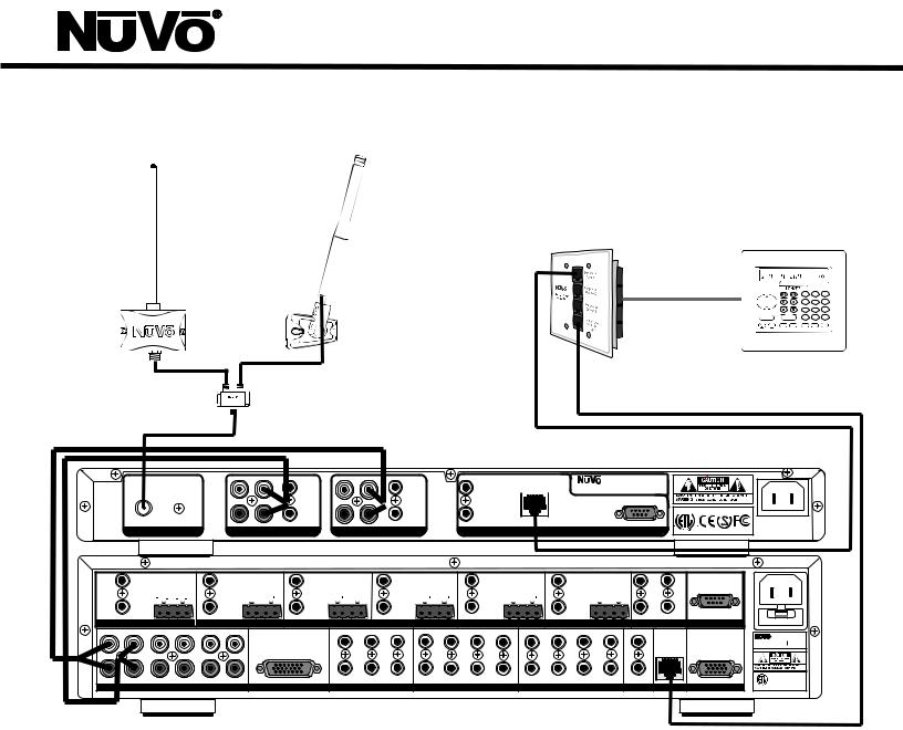
 NV-T2DF Wiring Diagram
|
|
|
1 |
2 |
3 |
VOLUME |
|
|
4 |
5 |
6 |
|
|
|
|||
|
|
|
7 |
8 |
9 |
SOURCE |
|
PLAY |
+10 |
0 |
ENT |
MUTE |
FM |
AM |
WX |
XM |
MENU |
NV-T2FXC SINGNAL
COMBINER
AUX IN |
OUT |
AUX IN |
OUT |
|
Model NV-T2DF |
|
|
|
USE ONLY NuVo |
TRIGGER |
|
TRIGGER |
NuVoNet |
Dual XM Tuner |
|
|
|
NV-T2PAS |
|
NuVo Techonlogies LLC•Cincinnati Ohio USA |
|
|
|
|||
ON=+12V |
L |
IR PASS-THRU |
|
|
|
|
||
L |
ON=+12V |
|
www.nuvotechnologies.com |
|
|
|
||
POWERED ANTENNA SYSTEM |
|
|
|
|
|
|
|
|
|
|
|
|
|
RS 232 |
|
|
|
|
AUDIO |
|
AUDIO |
|
TE RTE |
K |
TERTE |
|
R |
OUTPUT |
R |
IR INPUT |
|
IN |
|||
OUTPUT |
|
|
CM |
IN |
K |
|||
IN |
|
|
|
|
|
|
|
|
ANTENNA INPUT |
TUNER B |
|
TUNER A |
SYSTEM |
3033118 |
|
|
|
VARIABLE |
|
|
VARIABLE |
|
|
VARIABLE |
|
|
VARIABLE |
SPEAKER |
VARIABLE |
|
|
VARIABLE |
|
|
VAR. |
|
OUTPUT |
SPEAKER |
OUTPUT |
SPEAKER |
OUTPUT |
SPEAKER |
OUTPUT |
OUTPUT |
SPEAKER |
OUTPUT |
SPEAKER |
OUT |
|||||||
TIP=L |
40W/6 OHMS X 2 |
TIP=L |
40W/6 OHMS X 2 |
TIP=L |
40W/6 OHMS X 2 |
TIP=L |
40W/6 OHMS X 2 |
TIP=L |
40W/6 OHMS X 2 |
TIP=L |
40W/6 OHMS X 2 |
RS 232 |
||||||
LEFT |
RIGHT |
LEFT |
RIGHT |
LEFT |
RIGHT |
LEFT |
RIGHT |
LEFT |
RIGHT |
LEFT |
RIGHT |
|
||||||
RING=R |
|
|
RING=R |
|
|
RING=R |
|
|
RING=R |
|
|
RING=R |
|
|
RING=R |
|
|
|
|
FIXED |
|
|
|
FIXED |
FIXED |
|
FIXED |
|
|
FIXED |
|
|
|
FIXED |
|
FIX. |
|
|
|
OUTPUT |
|
|
|
OUTPUT |
OUTPUT |
|
OUTPUT |
|
|
OUTPUT |
|
|
|
OUTPUT |
|
OUT |
|
|
|
ZONE 1 |
|
|
ZONE 2 |
ZONE 3 |
|
ZONE 4 |
|
|
ZONE 5 |
|
|
ZONE 6 |
|
ZONE 7 |
ZONE 8 |
PROGRAM |
||
1 |
2 |
3 |
4 |
5 |
6 |
1 |
2 |
3 |
1 |
2 |
3 |
4 |
1 |
2 |
3 |
SUM1 |
SYS ON |
CONNECT TO |
CONNECT TO |
|
|
|
|
|
|
CONNECT TO |
|
|
|
|
|
|
|
|
|
|
|
||
|
L |
|
L |
|
L |
NV-I8X |
|
|
|
|
|
|
|
|
|
|
|
NV-I8EZP1 |
NV-I8X |
|
|
|
USE NV-SLC1 |
|
|
|
|
|
|
|
|
|
|
|
USE NV-NC1 |
USE NV-SLC1 |
|||
|
|
|
|
|
|
|
|
|
|
|
|
|
|
|
|
|
|||
|
|
|
|
|
|
CABLE |
|
|
|
|
|
|
|
|
|
|
|
CABLE |
CABLE |
|
R |
|
R |
|
R |
|
|
|
|
|
|
|
|
|
|
|
|
|
|
1 |
2 |
3 |
4 |
5 |
6 |
4 |
5 |
6 |
5 |
6 |
7 |
8 |
4 |
5 |
6 |
SUM2 |
EXT. MUTE |
|
|
|
|
|
|
|
|
|
|
|
|
|
|
|
|
||||||
|
|
SOURCE INPUTS |
|
|
SOURCE LINK |
SOURCE STATUS |
|
ZONE TRIGGER OUTPUTS |
|
|
EMITTER OUTPUTS |
|
SYSTEM |
NETWORK |
DIGITAL LINK |
||||
USE CNLY WITH 250V FUSE
MODEL NV-I8M
SIX SOURCE EIGHT ZONE
AUDIO DISTRIBUTION SYSTEM
|
|
120V 60Hz 500W |
FUSE:T5 A |
NuVo Technologies Cincinnati Ohio USA
www.nuvotechnologies.com |
CONFORMS TO
UL STD.6500 C 
 US CERTIFIED TO
3033118 CAN/CSA STD.E60065
Diagram is shown with the NuVo Concerto System and NuVoNet.
NV-T2DF Package Contents:
1 NV-T2DF Dual AM, FM, WX Tuner
1 NV-T2FAA Active AM/FM Antenna
1 NV-T2RC3 Remote Control
2 NV-RCA1 Stereo RCA Audio Cables
1 NV-AC1 2 Meter Coaxial Antenna Cable
1 NV-PC2 North American Power Cable (North American model only) 1 pr. NV-REM1U Single Space Rack Ear Mounts
NV-T2DX Package Contents |
NV-T2DFX Package Contents |
1 NV-T2DX Dual XM Tuner |
1 NV-T2DFX Dual AM/FM/WX and XM Tuner |
1 NV-T2XAA Active XM Antenna |
1 NV-T2FAA Active AM/FM Antenna |
1 NV-FBC F-Type Barrel Connector |
1 NV-T2XAA Active XM Antenna |
1 NV-RC3 Remote Control |
1 NV-T2AAC AM/FM/XM Signal Combiner |
2 NV-RCA1 Stereo RCA Audio Cables |
1 NN-FBC F-Type Barrel Connector |
1 NV-PC2 North American Power Cable |
1 NV-T2RC3 Remote Control |
1 pr. NV-REM1U Single Space Rack Ear Mounts |
2 NV-T2RCA1 Stereo RCA Audio Cables |
|
1 NV-PC2 North American Power Cable |
|
1 pr. NV-REM1U Single Space Rack Ear Mounts |
Page 5
10 |
11 |
12 |
13 |
14 |
15 |
|
Model NV-T2DF |
Tuner A |
|
SELECT |
|
|
Dual FM/AM/WX Tuner |
|
|
|
|
|
|
|
|
- |
|
|
|
|
FM 94.1 Stereo |
-–- |
|
|
REMOTE |
-–- |
|
||
STANDBY SENSOR |
Classic Rock |
– |
|
||
|
|
||||
|
|
|
|
|
|
|
|
|
FM STEREO•AM•WEATHER |
PUSH TO |
|
|
|
|
|
|
ENTER |
DISPLAY MEMORY MENU PRE/DIR SOURCE ON-OFF Tuner B SELECT
CATEGORY |
|
|
PRESET/DIRECT |
|
AM |
550 |
-- |
|
|
|
|
- |
|
||||
|
|
|
|
|
–-–- |
|
||
|
|
|
|
|
|
|
– |
|
< |
1 |
2 |
3 |
4 |
5 |
|
|
|
< |
6 |
7 |
8 |
9 |
0 |
FM STEREO•AM•WEATHER |
PUSH TO |
|
|
|
ENTER |
||||||
DISPLAY
CATEGORY
<
<
MEMORY MENU PRE/DIR SOURCE ON-OFF
PRESET/DIRECT
1 |
2 |
3 |
4 |
5 |
6 |
7 |
8 |
9 |
0 |
1 |
2 |
3 |
4 |
5 |
6 |
7 |
8 |
9 |
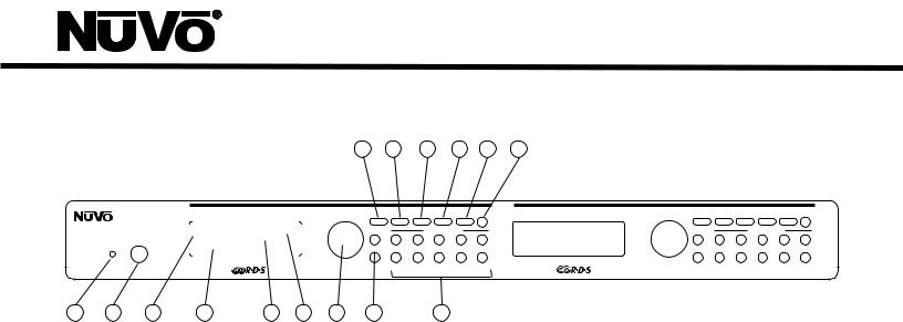
Front Panel
1.Stand-by LED: This LED (Light Emitting Diode) indicates that the T2 is plugged into an AC power source.
2.Remote Sensor: This IR (Infrared) receiver allows wireless remote control of the T2 functions. This IR input is active, even when it is used in conjunction with the direct IR input on the back panel.
3.Frequency and Band Display: The display indicates the band AM, FM, or WX (Weatherband)and station frequency, or the XM station being received.
4.Preset/ RDS Display: This is a display of customized preset information, or RDS (Radio Data Service) information transmitted with the station's broadcast. NuVoNet allows this to scroll automatically on the Concerto Display Pads (pg. 20).
5.Stereo: This indicates whether the FM signal reception is stereo. No display indicates mono. The T2 software allows an FM station preset to be set in mono mode (pg. 23).
6.Signal Strength: This indicates the level of signal being received at the tuned frequency. The signal level refers only to AM or FM band signals.
7.Select Knob: Turning the knob scrolls through the T2 menu options; pressing the knob selects the displayed menu option. When not in menu mode, the Select knob tunes up and down. Pushing the knob selects the station.
8.Category Up and Down: This function requires the use of the T2 installation software for AM/FM use. The XM categories are predefined by XM. Categories allow station selection to be set up according to specific listening genres.
9.Numeric Buttons: These buttons are programmable for direct station preset access. Customized alphanumeric strings can be defined in the setup software (pg. 23). They can also be used for direct frequency tuning for AM/FM or XM station tuning. These custom strings are displayed on the Display Pads of an integrated Concerto system whenever a preset is accessed.
10.Display Button: This button toggles between RDS information on and off.
11.Memory Button: The memory button provides you with a personal “notepad” to store and recall artist and song information originating from RDS or XM data being broadcast for future reference.
12.Menu: This button enters and exits the menu mode (pg. 14).
13.Pre/Dir: This toggles between numeric preset selection and direct station input.
14.Source: This button toggles between the available modes, AM, FM, WX (Weather Band), Aux or XM input on the XM versions.
15.On/Off: Turns each individual tuner on and off.
Page 6
USE ONLY NuVo |
AUX IN |
OUT |
AUX IN |
OUT |
|
Model NV-T2FX |
|
|
|
|
|
|
|
NuVoNet |
FM/AM/WX-XM Tuner |
|
|
|
|
NV-T2PAS |
|
TRIGGER |
|
TRIGGER |
NuVo Techonlogies LLC•Cincinnati Ohio USA |
|
|
|
|
POWERED ANTENNA SYSTEM |
L |
ON=+12V |
L |
ON=+12V |
IR PASS-THRU |
www.nuvotechnologies.com |
|
|
|
|
|
|
|
||||||
|
|
|
|
|
|
RS 232 |
|
|
|
|
R |
AUDIO |
R |
AUDIO |
IR INPUT |
TE RTE |
K |
TERTE |
|
|
|
OUTPUT |
|
OUTPUT |
|
|
CM |
IN |
K |
IN |
|
|
|
|
|
|
|
|
|
ANTENNA INPUT |
|
TUNER B |
|
TUNER A |
SYSTEM |
3033118 |
|
|
|
MADE IN CHINA
90~264V 50~60Hz 15W
1 |
2 |
3 |
4 |
5 |
6 |
7 |
8 |
9 |
10 |
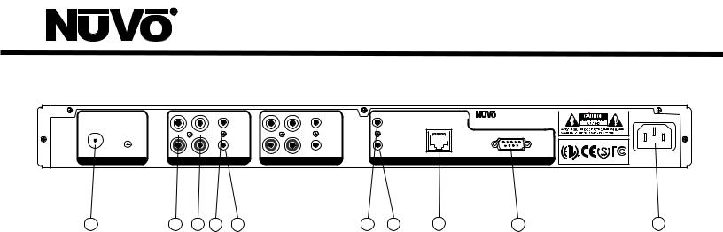
Back Panel
1.Antenna Input: Coax “F” connector brings in the signal input from the NuVo NV-T2FAA AM/FM or the NV-T2XAA XM active antenna (pg. 11).
2.Aux. Input: This stereo RCA connector is enabled through the advanced menu options (pg. 14), and allows an additional audio source to be connected and accessed through the tuner source selection.
3.Audio Output: A Stereo RCA output allows the tuner audio signal to be connected to an amplifier source, such as the NuVo Simplese, Essentia, and Concerto audio distribution systems.
4.Trigger ON: This voltage output provides a constant 12 volts when the Tuner is turned on.
5.Audio Output: This is a second stereo output designed to work with a tip, ring, sleeve 3.5mm stereo connection.
6.IR Pass-Thru: This 3.5mm connection is used to link IR control between two or more components used in the same installation.
7.IR Input: The single IR Input accepts a mono 3.5mm mono patch cable for receiving IR information from an external IR receiver without the use of an external IR emitter.
8.NuVoNet : This RJ45 connection is used with one of the Peripheral Device inputs on the Concerto EZ Port (see pg. 20) to enable direct one-to-one communication with the Concerto Display Pads.
10.RS232: This 9-pin DB9 connection allows serial communication with an external RS232 system. This may also be used for downloading a configuration from your computer to the internal flash memory of the tuner.
11.AC Power: This connects the T2 with an AC power source. When plugged into a live AC outlet the blue power LED (Light Emitting Diode) on the T2's front panel will remain lit. When neither tuner is on, the T2 is in standby mode and draws less than 2 watts of power. The T2 power supply is universal and will operate at a voltage range from 110V to 240V.
Page 7
 8
8
PWR |
A/B |
9 |
1 |
TUNER |
|
HOLD |
|
|
ALL OFF |
|
|
2
3
4
5
6
7
 ENTER
ENTER
SEEK
TUNE
CATEGORY
 SCAN
SCAN 
1 |
2 |
3 |
4 |
5 |
6 |
7 |
8 |
9 |
PRE |
0 |
ENT |
DIR
FM |
AM |
WX |
AUX |
10
11
12
13
T2 Tuner
REMOTE CONTROL
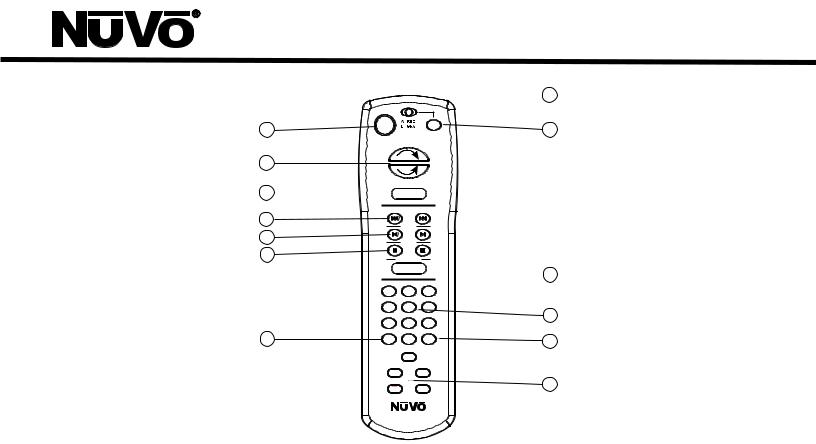
NV-T2RC3 Remote Control
1.Power: The power button turns the selected tuner on and off.
2.Scroll Buttons: These buttons are the equivalent of turning the front panel Select knob. The top button is the equivalent of turning the knob clockwise, and the bottom button is the equivalent of counterclockwise.
3.Enter: This button is the equivalent of pushing the Select knob on the front panel (see Front Panel #7).
4.Seek Up and Down: The seek buttons will tune to the next available station with the required signal strength for AM and FM use. The signal threshold can be adjusted higher or lower using the T2 Configurator software (see pg. 25), or through the advanced menu options on the front panel (see pg. 14).
5.Tune Up and Down: The tune function steps through each station frequency regardless of the frequency signal strength.
6.Category Up and Down: The category buttons step through each of the defined genre categories. Categories must be defined in the advanced settings of the T2 Configurator software for AM/FM use (see pg. 26).
7.Pre/Dir: The T2 allows up to 10 preset stations in each of up to 10 preset banks. This button scrolls through each of the defined banks and then to direct tuning. In direct tuning, you can use the numeric buttons to access a specific station frequency or XM channel number. Presets are selected by a single push of numeric button 0-9.
8.Tuner A & B LED: This LED glows red when Tuner A is selected and green when Tuner B is selected. This LED glows only momentarily when a button is pushed.
9.Tuner Selector: This button toggles between Tuner A and Tuner B operation.
10.Scan: The scan button tunes up to the next station with a signal strength above the programmed threshold for AM and FM or to the next XM channel and waits 5 seconds before automatically tuning to the next station. This uses the same signal level as the seek function.
11.Numeric Buttons: These buttons (0-9) are used to access a specific station frequency or choose a pre-defined station preset.
12.ENT: This button duplicates the enter function of the Enter button #3.
13.Source Buttons: These four buttons select each of the four available audio sources within the T2.
Page 8
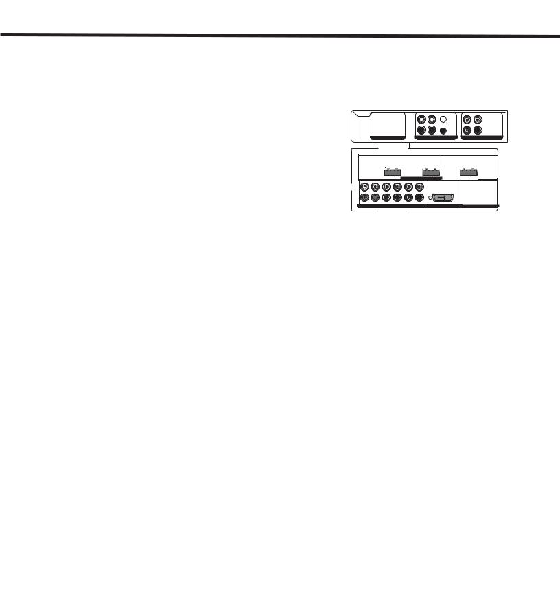
I. Installing the NV-T2 Dual Tuner
Fig . 1
Stereo Audio Connections
Each tuner has two audio output jacks. One is a stereo RCA connection, and the other is a stereo 3.5mm mini. The RCA output is an individual left and right channel connection made with a standard RCA cable. The other end is connected to the corresponding audio input on the back panel of the audio amplifier. An example of this is one of the source inputs on the back panel of a NuV0 audio distribution system, fig. 1.
The 3.5mm stereo output labeled “AUDIO OUTPUT” is also available for system connection. Compatible cables are
available with the male mini connection on each end, or with a Fig. 2 stereo RCA connection on one end, fig. 2.
Direct IR Control
The T2 is designed for IR control via IR received by an audio distribution system. In the NuVo Simplese or Essentia audio
distribution systems, the IR emitter outputs act as a repeater Fig. 3 to IR signals incident on the system keypads. The T2's wired IR
connector is a 3.5mm two-conductor (mono) jack labeled “IR INPUT.” Using a mono mini-to-mini patch cable, connect the IR emitter output of a Simplese or Essentia Main Unit to the IR INPUT on the T2. The two tuners in the T2 respond to separate IR codes, so the direct IR input replaces the need for external IR emitters placed over the IR receiver windows on the front of the unit, fig. 3. This connection is not used when using the Concerto NuVoNet system. The NuVo Essentia and Simplese systems are used for example, but the T2 is compatible with any audio system that is capable of repeating IR.
AUX IN |
OUT |
|
AUX IN |
OUT |
USE ONLY NuVo |
|
|
|
|
NV-T2PAS |
L |
TRIGGER |
L |
TRIGGER |
POWERED ANTENNA SYSTEM |
|
ON=+12V |
ON=+12V |
R |
AUDIO |
R |
AUDIO |
|
OUTPUT |
OUTPUT |
|
IN |
|
|
|
ANTENNA INPUT |
|
TUNER B |
|
|
TUNER A |
|
VARIABLE |
|
VARIABLE |
|
VARIABLE |
|
VARIABLE |
OUTPUT |
SPEAKER |
OUTPUT |
SPEAKER |
OUTPUT |
SPEAKER |
OUTPUT |
TIP=L |
40W/6 OHMS X 2 |
TIP=L |
40W/6 OHMS X 2 |
TIP=L |
40W/6 OHMS X 2 |
TIP=L |
LEFT RIGHT |
LEFT RIGHT |
LEFT RIGHT |
||||
RING=R |
RING=R |
|
RING=R |
|
RING=R |
|
FIXED |
FIXED |
FIXED |
FIXED |
OUTPUT |
OUTPUT |
OUTPUT |
OUTPUT |
|
ZONE 1 |
|
|
ZONE 2 |
|
ZONE 3 |
|
ZONE 4 |
1 |
2 |
3 |
4 |
5 |
6 |
1 |
2 |
3 |
|
|
|
|
|
|
CONNECT TO |
|
|
|
|
|
|
|
|
NV-I8X |
|
|
|
L |
|
L |
L |
|
USE NV-SLC1 |
|
|
|
|
|
|
|
|
|
|
|
|
|
|
|
|
|
CABLE |
|
|
|
R |
|
R |
R |
|
|
|
|
1 |
2 |
3 |
4 |
5 |
6 |
4 |
5 |
6 |
|
|
SOURCE INPUTS |
|
|
SOURCE LINK |
SOURCE STATUS |
||
|
|
AUX IN |
OUT |
|
AUX IN |
OUT |
|
USE ONLY NuVo |
|
|
|
|
|
|
|
|
NV-T2PAS |
|
L |
|
TRIGGER |
L |
TRIGGER |
POWERED ANTENNA SYSTEM |
|
|
|
ON=+12V |
ON=+12V |
||
|
|
|
R |
|
AUDIO |
R |
AUDIO |
|
|
|
|
|
OUTPUT |
OUTPUT |
|
IN |
|
|
|
|
|
|
|
ANTENNA INPUT |
|
|
TUNER B |
|
|
TUNER A |
|
VARIABLE |
|
VARIABLE |
|
|
VARIABLE |
|
VARIABLE |
OUTPUT |
SPEAKER |
OUTPUT |
SPEAKER |
OUTPUT |
SPEAKER |
OUTPUT |
|
TIP=L |
40W/6 OHMS X 2 |
TIP=L |
40W/6 OHMS X 2 |
TIP=L |
40W/6 OHMS X 2 |
TIP=L |
|
LEFT RIGHT |
LEFT |
RIGHT |
LEFT RIGHT |
||||
RING=R |
RING=R |
|
|
RING=R |
|
RING=R |
|
FIXED |
FIXED |
FIXED |
FIXED |
OUTPUT |
OUTPUT |
OUTPUT |
OUTPUT |
ZONE 1 |
ZONE 2 |
ZONE 3 |
ZONE 4 |
1 |
2 |
3 |
4 |
5 |
6 |
1 |
2 |
3 |
|
|
|
|
|
|
CONNECT TO |
|
|
|
|
|
|
|
|
NV-I8X |
|
|
|
L |
|
L |
|
L |
USE NV-SLC1 |
|
|
|
|
|
|
|
|
|
|
|
|
|
|
|
|
|
CABLE |
|
|
|
R |
|
R |
|
R |
|
|
|
1 |
2 |
3 |
4 |
5 |
6 |
4 |
5 |
6 |
|
|
|
||||||
|
|
SOURCE INPUTS |
|
|
SOURCE LINK |
SOURCE STATUS |
|
|
|
|
|
|
|
|
|
|
Model NV-T2DF |
|
|
|
|
|
|
||
|
|
|
|
|
NuVoNet |
|
Dual XM Tuner |
|
|
|
|
|
|
|||
|
|
IR PASS-THRU |
|
|
NuVo Techonlogies LLC•Cincinnati Ohio USA |
|
|
|
|
|
||||||
|
|
|
|
|
|
|
|
|
|
|
||||||
|
|
|
|
|
|
|
www.nuvotechnologies.com |
|
|
|
|
|
|
|||
|
|
|
|
|
|
|
|
|
RS 232 |
|
|
|
|
|
|
|
|
|
IR INPUT |
|
|
|
|
|
|
|
|
RTE |
K |
TERTEK |
|
|
|
|
|
|
|
|
|
|
|
|
|
|
|
|
|
|||
|
|
|
|
|
|
|
|
|
|
|
3033118 |
|
|
|
|
|
SPEAKER |
VARIABLE |
|
|
|
|
VARIABLE |
|
|
VAR. |
|
|
|
|
|
||
OUTPUT |
|
SPEAKER |
|
OUTPUT |
SPEAKER |
OUT |
|
|
|
|
|
|||||
40W/6 OHMS X 2 |
TIP=L |
|
40W/6 OHMS X 2 |
|
TIP=L |
40W/6 OHMS X 2 |
|
|
|
RS 232 |
|
|
|
|||
LEFT |
RIGHT |
|
LEFT |
RIGHT |
|
LEFT |
RIGHT |
|
|
|
|
|
|
|
||
|
|
RING=R |
|
|
|
|
RING=R |
|
|
|
|
|
|
|
|
|
|
|
FIXED |
|
|
|
|
FIXED |
|
|
FIX. |
|
|
|
|
|
|
|
|
OUTPUT |
|
|
|
|
OUTPUT |
|
|
OUT |
|
|
|
|
|
|
|
|
ZONE 5 |
|
|
|
ZONE 6 |
|
|
ZONE 7 |
ZONE 8 |
|
PROGRAM |
USE CNLY WITH 250V FUSE |
|||
1 |
2 |
3 |
4 |
|
1 |
2 |
3 |
|
SUM1 |
SYS ON |
CONNECT TO |
|
CONNECT TO |
|
MODEL NV-I8M |
|
|
|
|
|
|
|
|
|
|
|
|
|
|
SIX SOURCE EIGHT ZONE |
|||
|
|
|
|
|
|
|
|
|
|
|
NV-I8EZP1 |
|
NV-I8X |
|
AUDIO DISTRIBUTION SYSTEM |
|
|
|
|
|
|
|
|
|
|
|
|
|
120V |
60Hz 500W |
FUSE:T5 A |
||
|
|
|
|
|
|
|
|
|
|
|
USE NV-NC1 |
|
USE NV-SLC1 |
NuVo Technologies Cincinnati Ohio USA |
||
|
|
|
|
|
|
|
|
|
|
|
CABLE |
|
CABLE |
www.nuvotechnologies.com |
||
5 |
6 |
7 |
8 |
|
4 |
5 |
6 |
|
SUM2 |
EXT. MUTE |
|
|
|
|
CONFORMS TO |
|
|
|
|
|
|
|
UL STD.6500 |
||||||||||
|
|
|
|
|
|
|
|
|
|
|
|
|
|
|
CERTIFIED TO |
|
|
ZONE TRIGGER OUTPUTS |
|
|
|
EMITTER OUTPUTS |
|
SYSTEM |
NETWORK |
|
DIGITAL LINK |
3033118 |
CAN/CSA STD.E60065 |
||||
Page 9
 Loading...