

Page 1
INSTALLATION AND SAFETY INSTRUCTIONS
FOR YOUR SAFETY
WARNING: BE SURE THE ELECTRICITY TO THE WIRES
YOU ARE WORKING ON IS SHUT OFF; EITHER THE FUSE
IS REMOVED OR THE CIRCUIT BREAKER IS SHUT OFF.
GENERAL
You don’t need special tools to install this fixture. Be sure to
follow the steps in the order given. Under no circumstances
should a fixture be hung on house electrical wires, nor should a
swag type fixture be installed on a ceiling, which contains a
radiant type heating system. Read instructions carefully. If you
are unclear as to how to proceed, consult a qualified
electrician.
NOTE: Proper wiring is essential for the safe operation of this
fixture.
FIXTURE ASSEMBLY
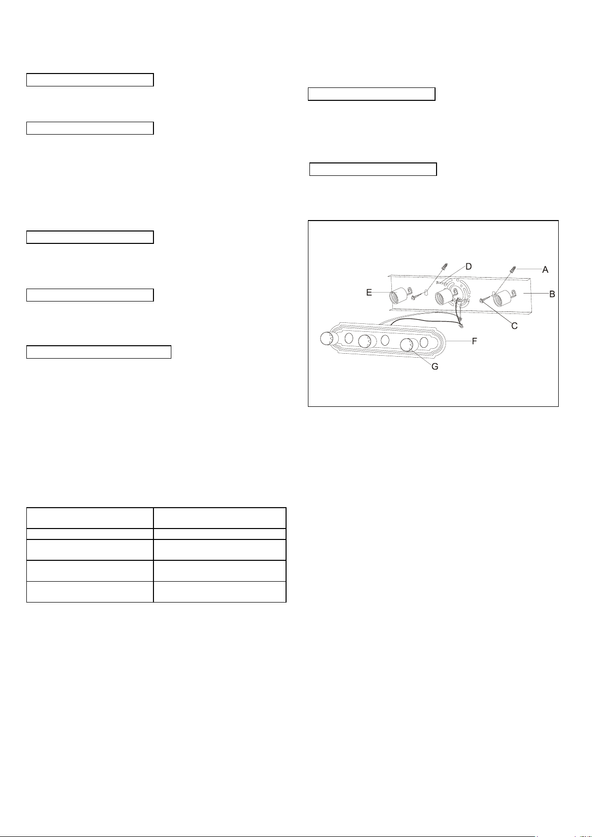
Carefully removed the fixture from the carton and check that all
parts are included as shown in figure. Be careful not to
misplace any of the screws or parts, which are needed to install
this fixture.
INSTALLATION
IMPORTANT: Do not attach fixture directly to outlet box.
STEP 1: Secure back plate (B) to outlet box and wall with outlet
box screws (D), plastic wall anchor (A) and wood
screws (C).
GROUNDING INSTRUCTIONS
STEP 1: Insert the green grounding screw into the hole with
two raised dimples on the back plate (B). Wrap the
ground wire from the fixture (if supplied) around the
green grounding screw, then connect it to ground
wire from the outlet box (if not fixed on the outlet box)
using a wire connector (not supplied). If ground wire
from the fixture is not supplied, wrap the ground wire
(if not fixed on the outlet box) from the outlet box
around the green grounding screw and tighten it.
NEVER CONNECT GROUND WIRE TO BLACK OR WHITE
POWER SUPPLY WIRES.
STEP 2: Take note of the color of the wire(s) on your fixture.
Identify which group your fixture wire(s) falls into and
connect the wires according to the directions below:
GROUP A: Connect to Black
House Wire
GROUP B: Connect to White
House Wire
BLACK
WHITE
*PARALLEL WIRE (round &
smooth)
*PARALLEL WIRE (square &
ridged)
WHITE OR GREY WITH
TRACER
WHITE OR GREY WITHOUT
TRACER
BROWN GOLD OR BLACK
WITHOUT TRACER
BROWN, GOLD OR BLACK
WITH TRACER
*NOTE: When parallel wire (SPT-I & SPT-2) is used, the tracer
wire is square shaped or ridged and the less tracer wire is
round in shape or smooth (seen best when viewed from wire
end.)
STEP 3: Take your fixture wire(s) from group A and place
evenly against the black wire from the outlet box. Do
NOT twist wires together before using wire
connectors.
STEP 4: Fit a wire connector (not supplied) over the wires and
screw the connector clockwise until you feel a
firmness.
STEP 5: Try gently to pull the connector off the wires. If you
can pull the connector off, carefully re-do steps 3 and 4,
as above, and check again for a firm connection.
STEP 6: Connect the fixture wire from group B to the white wire
from the outlet box in the same manner. Make sure no
bare wires can be seen outside wire connectors.
FINAL ASSEMBLY
STEP 1: After wires are connected, tuck them carefully inside
outlet box. Push the face plate (F) firmly over the
sockets (E) and against the wall. Secure face plate
(F) with cups (G).
STEP 2: Install lamps. (Please do not exceed the maximum
capacity recommended on the socket.)
CLEANING
To clean, wipe fixture with a soft cloth. Clean glass with a mild
soap. Do not use abrasive materials such as scouring pads or
powders, steel wool or abrasive paper.
Line art shown may not exactly match the fixture enclosed.
However, the installations do apply to this fixture.
ITEM NO:60-296 60-297 60-298 60-299
60-300 60-301 60-302 60-303
60-304 60-305 60-306 60-307
60-308 60-309 60-310 60-311
60-312 60-313 60-314 60-315
60-1284 60-1285 60-1286 60-1287
 Loading...