

Page 1

FEB 2012
NuVinci
®
N360 Technical Manual
Technical Manual
Technisch Handboek
Technisches Handbuch
Teknisk Håndbog
EN
EN
NL
DE
DK
Page 2
EN
1. THE NUVINCI® N360 SYSTEM
2
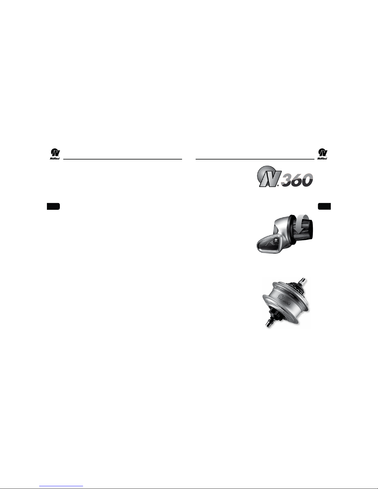
NuVinci N360 Shifter
Controlling the ratio of the N360
is simply a matter of rotating the
shifter grip. The shifter display
indicates ratio as a simple
graphic; a hill for slower speeds
and a at for faster speeds.
Since there are no xed gears,
the exact ratio is determined by
your comfort level. Ratio changes
can be made even while pedaling
under high torque.
NuVinci N360 CVP
Ratio changes occur within the
hub, smoothly and easily via
internals that are sealed for life
and maintenance-free. The hub is
compatible with rim, disc, or roller
brakes, and has an integrated
high-quality freewheel that is
serviceable.
The NuVinci N360 is the third
generation continuously variable
drivetrain from Fallbrook
Technologies. The N360 is a
light-weight and durable drivetrain
that shifts smoothly and seamlessly
across the full ratio range
without steps or gaps.
TABLE OF CONTENTS
1. The NuVinci® N360 System .........................2
2. Assembly of Components
Wheel Building ..............................3
Installing the Sprocket..........................4
Hub Interface Orientation and Installation Angle . . . . . . .5
Installing the Hub Interface ......................5
Assembly of Shifter ...........................7
Installing Shift Cable Housing ....................8
Installing Shift Cables and Hardware ...............9
3. Rear Wheel Installation / Removal
Fitting the Rear Wheel ........................11
Disconnecting the Rear Wheel...................12
4. Basic Maintenance & Care
Adjusting Cable Slack ........................13
Cleaning..................................13
Lubrication ................................13
5. Service Instructions
Replacing Shift Cables ........................14
Adjusting Shifter Resistance.....................15
Resetting CVP to Full Overdrive ..................15
Servicing or Replacing Freewheel ................18
Removing the Brake Conguration................19
Installing the Brake Conguration ................19
6. Technical Data
N360 Specications .........................20
Exploded View .............................21
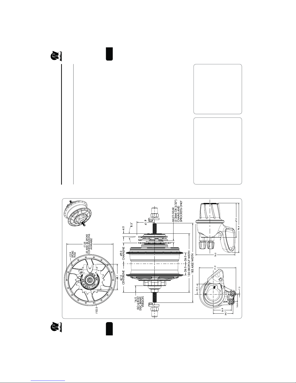
N360 CVP and Shifter Dimensions ...............23
7. Intellectual Property Notice.........................24
8. Warranty......................................25
1
EN
Page 3

EN
4
4
1
2.2
The NuVinci N360 is incompat-
ible with 1/8 inch (3.18mm)
single-speed chains and sprock-
ets. Use 3/32 inch (2.3mm)
chains and sprockets only.
Installing the Sprocket
Remove the anti-shift
retainer (1) by pulling rmly away
2. ASSEMBLY OF COMPONENTS
from the NuVinci CVP.
2.2
1
2
2.3
Use of incompatible chains can
result in interference with the
hub interface and damage to
N360 components and may
result in a dangerous condition
for the rider.
Install a standard 9-spline,
3/32 inch (2.3mm) sprocket (2),
followed by the supplied sprocket
spacer (3, if required), and secure
2.3
3
See Section 6 “TECHNICAL
DATA” for Sprocket Ratio
for sprockets that are 3/32
inch (2.3mm) thick at the inner
diameter. If the inner diameter
is 0.17- 0.18 inch (4.3-4.5mm)
thick, the spacer should not be
used.
with the sprocket snap ring (4).
fThe sprocket spacer is intended
fThe N360 is compatible with
If the sprocket is asymmetric,
incorrect installation can result
in interference with the hub
interface and damage to N360
components and may result in
a dangerous condition for the
requirements.
16 to 22 tooth sprockets.
chainline closest to the CVP.
fInstall the sprocket for a
rider.
If hub interface is not installed
immediately following the
sprocket, replace the anti-shift
retainer (1).
135mm
2.1
Installation and repairs must be
made by a qualied bicycle
mechanic.
This manual assumes a level of
knowledge and skill consistent
with that of an experienced
bicycle assembler or bicycle
mechanic.
2. ASSEMBLY OF COMPONENTS
EN
1
The anti-shift retainer (1)
Wheel Building
provides 135mm spacing, and
should remain on the CVP during
lacing and wheelbuilding.
2.1
#13 / 2.34mm.
#14 / 2.00mm.
fMaximum spoke diameter is
fMinimum spoke diameter is
Suggested lacing is a 2-cross
fUse a 2-cross pattern only if
pattern for 26-inch and 700c
wheels.
the rim allows the nipples to
be effectively in-line with the
spokes.
For 24-inch or smaller wheels a
1-cross pattern is suggested.
Radial lacing is not recommended.
3
Page 4
EN
6
2.7
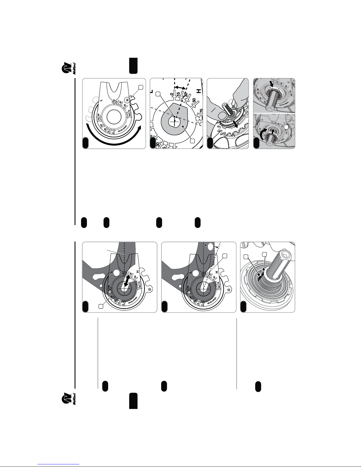
washer (6) can be installed
Prior to installation, set the hub
interface to the full overdrive (H)
position (4).
Suspend the hub interface
2. ASSEMBLY OF COMPONENTS
2.7
over the right hand axle, and
2.8
0º
fAlternatively, a no-turn
align the axle ats (5) with the
installation angle from Step 2.5.
4
5
2.8
over the hub interface to align
the installation angle.
When the installation angle is
aligned, ensure the hub interface
2.9
20º
6
is set to full overdrive (H) and seat
the hub interface fully onto the shift
driver and the spline nut until it is
ush with the spline nut, as shown.
2.9
Thread the RH Nut (7),
serrations facing outward, onto
the axle and tighten to 10-15 Nm
(7-11 ft-lbs).
2.10
20º
Install the rear wheel per Section 3.
2
7
2.10
3
2
1
2.4
Use the uninstalled hub
Hub Interface Orientation
2. ASSEMBLY OF COMPONENTS
and Installation Angle
interface (1) to determine the
desired orientation.
2.4
2.5
parallel to the chain stay or
seat stay cable routing.
fTypical orientation is forward,
fMove the hub interface along
With the hub interface
the dropout to ensure clearance
at different axle positions.
oriented correctly inside the right
2.5
EN
interface to determine your
approximate installation angle.
dropout, the installation angle (2)
is the indicated angle of the drop-
out (20 degrees in this example).
fUse the markings on the hub
Installation Angle:__________
Installing the Hub Interface
2.6
Ensure that markings between
Remove the anti-shift retainer, if
installed (reference Step 2.2).
the splined nut (2) and the shift
driver (3) are aligned. If not,
2.6
refer to Step 5.6.
5
Page 5

EN
150m
m
8
5
6
4
4
2.13
Route cable housing as shown
Measure, cut and install the
from the shifter to the hub interface.
Installing Shift Cable Housing
2.13
1
2.11
appropriate length cable housing
2.14
mended for both shift cables.
fFull-length housing is recom-
(4) for the bicycle.
fMake sure that the cable
2.14
housing lengths are sufcient
to allow an extreme turning
angle. Also consider the inu-
ence of adjustable handlebars
and stems on the cable housing
lengths.
2
moveable for axle adjustments.
fThe cable housing must remain
Secure cable housing to the frame.
fAvoid tight bends when install-
2.12
ing the shift cable housing.
ing unsupported at the hub
interface (5) to ease installation
and removal of the shift cable
fLeave at least 150mm of hous-
hardware.
With housing length correct, install
end caps (6) at both ends of each
housing.
3
Slide the shifter (1) onto the
Assembly of Shifter
Install right brake lever according
2. ASSEMBLY OF COMPONENTS 2. ASSEMBLY OF COMPONENTS
to the manufacturer’s instruction.
2.11
onto the handlebar according
fInstall the right hand grip (2)
handlebar.
EN
Position the shifter such that
to the manufacturer’s instruc-
tions.
the display (3) is visible to the
2.12
2 .18
Never use lubricants or solvents
to install handlebar grips.
Make sure that the shifter
and the brake lever function
2.0-2.5 Nm (18-22 in-lbs).
fTighten the clamp bolt to
rider and the cables will be
unobstructed.
properly and are unobstructed
(re-adjust if necessary).
Never ride without the
handlebar grips. The turning
grip of the shifter could become
loose. This can result in a
severe injury.
7
Page 6
EN
10
7
2.17
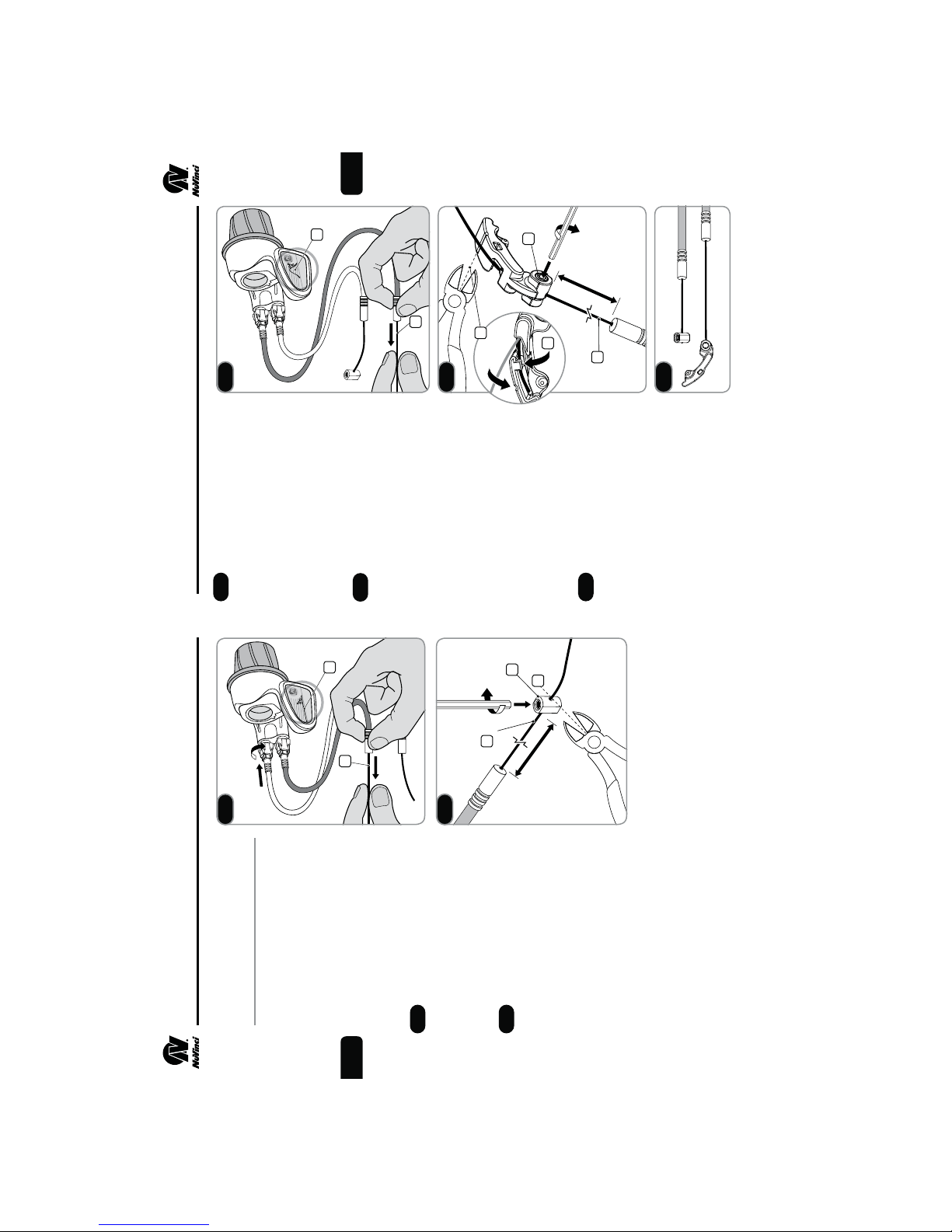
Pull the overdrive shift
cable (6) rmly at the hub interface
until it stops, checking to make
sure that the NuVinci shift
2.17
cable and UD cable stop are
free and unobstructed.
fMake sure the underdrive shift
indicator goes into a steep hill (7).
2
6
Pass the overdrive shift
cable (8) through the OD latch (9)
and secure the OD latch at the
distance shown while pulling the
2.18
cable rmly.
10
2.18
is seated fully at the shifter.
cable and torque to 1.5-2.0
fEnsure that the cable housing
fUsing a 2mm allen, secure the
9
111mm
11
OD latch marking (10), and
tuck the remaining cable length
Nm (13-18 in-lbs).
fCut the excess cable at a the
4
5
8
The cable hardware should
into the OD latch as shown (11).
appear as shown. Assemble to
CVP per Step 3.2 and adjust cable
2.19
2.19
slack with barrel adjusters per
Step 4.2.
1
2.15
completely clockwise (in) to
2. ASSEMBLY OF COMPONENTS 2. ASSEMBLY OF COMPONENTS
Installing Shift Cables and
Hardware
Pass the shift cables through the
appropriate cable housing and
fThread both barrel adjusters
ensure the housing is seated
completely into the shifter.
EN
3
2.16
Pull the underdrive shift cable
provide maximum installation
slack.
(1) rmly at the rear axle location
until it stops, checking to make
2.15
Pass the underdrive shift cable
sure that the NuVinci shift indica-
tor (2) goes completely at.
(3) through the UD cable stop (4)
2.16
120mm
is seated fully at the shifter.
cable and torque to 1.5-2.0
Nm (13-18 in-lbs).
fEnsure that the cable housing
and secure the UD cable stop at
the distance shown while pulling
the cable rmly.
fUsing a 2mm allen, secure the
maximum of 2.0mm from the
fCut the excess cable at a
end of the UD cable stop (5).
9
Page 7
EN
3
A
C
B
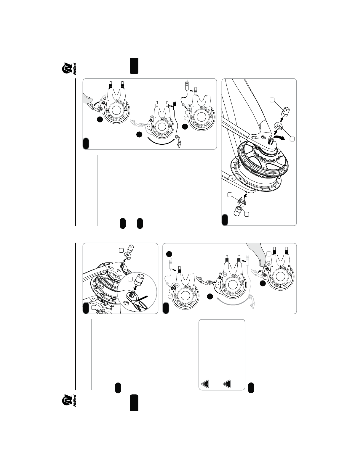
3.3
4
12
4
easy access to the shift cable
Disconnecting the Rear
3. REAR WHEEL INSTALLATION/REMOVAL
3.1
3. REAR WHEEL INSTALLATION/REMOVAL
Fitting the Rear Wheel
f Shift to a position that allows
Wheel
1
rear frame, making sure not to
obstruct shift cables.
fPlace the rear wheel into the
hardware.
following steps A, B and C.
Loosen and/or remove the
Remove shift cable hardware
3.3
3.4
1
2
For rim or roller brake applica-
f
axle nuts (3) and the no-turn
washers (4).
Boss
Tightening torque 30 – 40 Nm
Slide one no-turn washer (1)
each onto each axle end. The
serrations of the no-turn washer
must bear against the dropout of
3.1
the frame. The rectangular boss
fMount the axle nuts (2).
must engage in the dropout of the
frame.
tions, disconnect the rear brake
according to the manufacturer’s
instructions.
f Remove the rear wheel.
A
B
3.2
Improper installation of the
(266-350 in-lbs).
cations, connect the rear brake
according to the manufacturer’s
no-turn washer will result in
instructions.
fFor rim and roller brake appli-
3
3.4
damage to the dropout and
the hub.
Over-tightening may damage
parts. Under-tightening can
result in the axle sliding in the
dropouts.
following steps A, B and C.
Install the shift cable hardware
3.2
3
C
EN
11
Page 8

EN
1
3
14
5.1
Replacing Shifter Cables
Remove cable hardware from both
5. SERVICE INSTRUCTIONS
cables and remove shift cables
2
Remove the Phillips screw
from housing.
(1) on the bottom of the NuVinci
shifter and remove the bottom
5.1
5.2
Using a small at screwdriver
cover by pulling lightly on the
access tab (2).
or pointed object, extract the
cable anchors (3) and shift cables
5.2
5
4
5.3
Install one shift cable, allowing
individual cable anchors.
(4) from the grip pulley.
fRotate the grip to access
the shifter housing (5) to guide the
cable around the internals until it
comes out the other side. Guide
5.3
7
6
5.4
Pull the cable through the
barrel adjuster until the cable
the cable through the closest barrel
adjuster (6).
anchor seats fully into the grip
5.4
next cable for installation and
repeat 5.3 and 5.4.
pulley (7).
fRotate the grip to position the
Reinstall the bottom cover and
screw (1). Torque to 0.2-0.3 Nm
(2-3 in-lbs).
2
1
4.1
shifter.
Cable slack can be determined
Adjusting Cable Slack
4. BASIC MAINTENANCE AND CARE
with the barrel adjusters (1) at the
Cable slack can be adjusted
4.1
4.2
4.2
0.5mm of slack is ideal. Cable
slack of more than 2.0mm may
cause decreased shift perfor-
mance and shift cable durability.
ditional cable slack may be
by pulling lightly on the cable
f
housing (2) at the shifter and
noticing any slack.
desired to ease shift cable
f For rear wheel removal, ad-
hardware removal, which can
be obtained with the barrel
adjusters.
EN
provided with permanent
lubrication and the CVP
internals are maintenance-free
fThe NuVinci N360 CVP is
Lubrication
fYour NuVinci N360
Cleaning
for the life of the product.
components are sealed and
well protected from the external
environment. However, do not
use water under pressure (such
freewheel mechanism is
serviceable.
fThe NuVinci N360 internal
as pressure washers or water
the chain’s service life.
fRegular lubrication will extend
jets) for cleaning to prevent
malfunctions due to water
penetration.
should clean your bicycle in
shorter intervals so that winter
road salt cannot cause any
fDuring the winter season, you
damage.
fDo not use aggressive cleaners.
13
Page 9

EN
L
3
4
16
5.6
If the spline nut (3) and
shift driver (4) markings are not
aligned, full overdrive will need to
5.6
3
5.5
full overdrive should result in
the hub/wheel rotating 1.8-2
times for every 1 rotation of the
fIf the markings are not obvious,
be reset.
H
2
CVP sprocket.
5.7
Set the hub interface to the full
underdrive (L) position (note this
is opposite of normal installation).
Reinstall the hub interface (angular
5.7
position is unimportant), leaving
used to shift the CVP into full
overdrive by hand in the
following steps.
fThe hub interface will be
the RH Nut uninstalled.
in full overdrive with an anti-shift
retainer installed (reference Step
5. SERVICE INSTRUCTIONS 5. SERVICE INSTRUCTIONS
Resetting CVP to Full Overdrive
2.2).
The NuVinci N360 CVP is shipped
installed, full ratio range of the
CVP may be unavailable, and
full overdrive will need to be
fIf the hub interface is incorrectly
reset.
If installed on the bicycle, shift
the CVP into overdrive (H) as far
as possible, and remove the rear
wheel per Section 3.
EN
Remove the RH Nut (2) that
secures the hub interface (3), then
remove the hub interface by lifting
5.5
carefully from underneath.
15
Page 10

EN
15
16
5.10
fReference Exploded Diagram P.21
Set the NuVinci N360 CVP
in full overdrive with the front
shifter or hub interface prior to
removal.
Remove the rear wheel per Section 3.
Remove the hub interface per Step 5.5.
Reference the Exploded Diagram
on Page 22. Remove the sprocket
snap ring (12), sprocket spacer
Servicing or Replacing
5. SERVICE INSTRUCTIONS
Freewheel
(13, if installed), and sprocket (14).
19
5.11
Remove the snap ring (15) on
the shift driver, and remove the
5.10
use a medium-weight oil or
fIf servicing or replacing,
freewheel assembly (16).
17
18
Remove the interior snap ring
lightweight water-resistant
grease and check function.
(17), needle bearing (18), and RH
shield (19) if these components are
being replaced.
5.11
18
Install the serviced / new free-
wheel components according to
the Exploded Diagram on Page 22.
Install sprocket and hub interface
per Section 2.
Install the rear wheel per Section 3.
5.8
counter-clockwise
Install the NuVinci N360 CVP
5. SERVICE INSTRUCTIONS
into a vice or xture as shown,
5.8
installation in the bicycle frame
is possible, tightening only the
left hand side no-turn washer
and axle nut to allow rotation
fIf a vice is not available,
clamping on the left hand axle ats.
of the hub interface.
the full overdrive (H) position
While driving the CVP clockwise
toward
with the sprocket (1), rotate the
hub interface (2)
5.9
EN
1
2
5.9
hub interface is unimportant
in this step.
hub/wheel should rotate
approximately 1.8-2 times
for every 1 rotation of the
fThe indicated position of the
until a rm stop is felt. Repeat this
rotation 2-3 times by driving the
CVP clockwise and rotating the hub
interface back and forth, ending at
a rm stop toward (but likely not at)
the full overdrive (H) position.
fWhen in full overdrive, the
CVP sprocket.
When full overdrive is found,
remove the hub interface per
At all times while rotating
the wheel, sprocket, or hub
interface, be careful not to
catch or pinch ngers.
Step 5.5.
Check to make sure the mark on
the spline nut and shift driver align
per Step 5.6.
Install hub interface per Steps 2.4
through 2.10.
17
Page 11

EN
20
21/38, 22/40,
Hub Colors Silver or Black
N360 Specications
6. TECHNICAL DATA
Installing the Brake
Conguration
Spoke Configurations 32 or 36 Hole
Brake Configurations Disc, Rim or Roller
Speed Ratio Infinitely Variable
and apply a high strength thread
locking compound (equivalent
fInstall the roller brake adapter (7)
Installing Roller Brake Hardware
1.8 Overdrive)
within Ratio Range
Ratio Range 360% Nominal
(0.5 Underdrive to
Shifting Variable Twist Grip,
3/4 Turn
Drop-Out Width 135 mm, Horizontal
or Vertical
to Loctite® 277™) around one
complete thread of the brake lock
ring (6).
BKAD-01, install and torque the
brake lock ring (6) to 55-65 Nm
(41-48 ft-lbs).
fUsing NuVinci service tool N360-
fAfter installing roller brake, install
16-22 Tooth Supported
Axle Length 183 mm
Axle Threads M10x1
Chainline 49.0 ± 0.5 mm
Beltline 45.5 ± 0.5 mm
Sprockets
Rim Brake Hardware
sition until it seats fully, followed
and torque left hand nut (3) to
30-35 Nm (22-26 ft-lbs).
Installing
by the cupped washer (4).
fPress rim brake cover (5) into po-
26.0 mm
26.0 mm
can be used without exception)
standard 9-spline, not included)
(
larger front chainrings
Sprocket Ratio 1.8:1 Minimum
(16/29, 17/31, 18/33, 19/35, 20/36,
Spoke Flange Diameter 125.0 mm
Center to Left Spoke Flange
Center to Right Spoke Flange
Disc Brake Hardware
to 30-35 Nm (22-26 ft-lbs).
fInstall and torque left hand nut (3)
and brake shield (8) and applya
fInstall the disc brake adapter (9)
Installing
high strength thread locking
compound (equivalent to Loctite®
277™) around one complete
thread of the brake lock ring (6).
For the most up-to-date NuVinci
N360 CVP Owner and Technical
Manuals please visit us online at
www.nuvinci.com/support
BKAD-01, install and torque the
brake lock ring (6) to 55-65 Nm
(41-48 ft-lbs).
fUsing NuVinci tool N360-
to 30-35 Nm (22-26 ft-lbs).
fInstall and torque left hand nut (3)
fReference Exploded Diagram P.21 fReference Exploded Diagram P.21
Removing the Brake
Conguration
5. SERVICE INSTRUCTIONS
Remove the rear wheel per Section 3.
to remove the brake lock ring
(6), and remove the roller brake
Vinci service tool N360-BKAD-01
adapter (7) from the hub.
fRemove left hand axle nut (1), left
Removing Rim Brake Hardware
hand nut (3).
hand no-turn washer (2), and left
fRemove left hand axle nut (1), left
Removing Roller Brake Hardware
fSecure the wheel and use Nu-
EN
hand no-turn washer (2), left hand
nut (3), and cupped washer (4).
remove the rim brake cover (5).
fUsing a thin at device, pry and
hand no-turn washer (2), left hand
nut (3), and cupped washer (4).
fRemove left hand axle nut (1), left
Removing Disc Brake Hardware
and remove both the brake shield
(8) and disc brake adapter (9)
remove the brake lock ring (6),
from the hub.
NuVinci tool N360-BKAD-01 to
fSecure the wheel and use
19
Page 12

(Optional - to be
used with 2.3mm
Right (Drive) Side
EN
11 2
13
15
thick sprockets)
17
19
110
12
14
(Not Supplied)
1618
22
Snap Ring (Interior)
16 Freewheel Assy
17
18 Needle Bearing
19 RH Shield
Snap Ring (Freewheel)
12 Sprocket Snap Ring
13 Sprocket Spacer
14 Sprocket
15
1 AxleNut
2 No-Turn Washer
10 RH Nut
11 Hub Interface
Left (Non-Drive) Side
5
4
A
Rim Brake
Configuration
6. TECHNICAL DATA 6. TECHNICAL DATA
EN
B
3
Roller Brake
Configuration
1
6 Brake Lock Ring
7 Roller Brake Adapter
8 Brake Shield
9
7
8
6
4
C
2
Disc Brake
Configuration
DIAGRAM KEY DIAGRAM KEY
9 Disc Brake Adapter
2 No-Turn Washer
3 Left Hand Nut
4 Cupped Washer
5 Rim Brake Cover
Rim Brake Configuration
Roller Brake Configuration
Disc Brake Configuration
C
B
1 Axle Nut
A
21
Page 13
EN
®
®
24
Technology components and/or the
®
CVP Model N360 Hub and Shifter
®
The NuVinci
7. INTELLECTUAL PROPERTY NOTICE
By purchasing and/or using these NuVinci
Technology components sold herewith are to be used only
®
Technology components to your vendor within three (3) days for a full
®
bicycle incorporating them, you agree to the following terms and conditions. If
you do not want to be bound by these terms and conditions, you must return the
NuVinci
Technology components for any other use or purpose, including without limita-
tion reverse engineering or reproduction. Any unauthorized use of the NuVinci
Technology components is not recommended, will void any applicable warranties
and, to the extent such use leads to any improvements to or inventions from those
components, and as allowed under applicable law, Fallbrook Technologies Inc.
in the rear wheel of a bicycle for usual and customary rear hub purposes and in
accordance with the accompanying instructions. You agree not to use the NuVinci
refund. The NuVinci
and its licensees shall have a royalty free, worldwide, perpetual, non-exclusive
shown in
millimeters.
All dimensions
Europe
Amsterdam, Holland
+31 20 640 8600
(688-4624)
Technology components sold herewith, including, but not limited to
7,410,443; D548,655; Dansk Patent Nos. 1023545 and 1235997;
®
UK patent Nos. GB 1023545 and GB 1235997; Brevetto Nos. 1023545 and
the rear hub and gear shifter, are protected by U.S. patents 6,241,636; 6,419,608;
license to all rights in any such inventions or improvements.
The NuVinci
1235997 Italy; and other foreign patents. Other U.S. and foreign patent applica-
6,551,210; 6,676,559; 6,689,012; 6,945,903; 7,011,600; 7,032,914;
7,044,884;
2012
tions are pending for Fallbrook Technologies Inc.
Fallbrook, NuVinci and their stylized logos and associated elements are
trademarks or registered trademarks of Fallbrook Technologies Inc. All rights
reserved. ©
North American Ofce
Fallbrook Technologies Inc.
505 Cypress Creek Road, Suite C
Cedar Park, TX 78613
1-888-NuVinci
Tel: +1 (512) 279-6200
Fax: +1 (512) 267-0159
www.nuvinci.com
6. TECHNICAL DATA
EN
23
Page 14
EN
2012
THIS LIMITED WARRANTY IS THE SOLE AND EXCLUSIVE WARRANTY MADE BY FALLBROOK
WITH RESPECT TO THE PRODUCT, AND IS GIVEN IN LIEU OF ANY OTHER WARRANTY. TO
THE EXTENT ALLOWED BY APPLICABLE LAW, ANY AND ALL EXPRESS OR IMPLIED WARRAN-
TIES NOT SET FORTH HEREIN ARE WAIVED AND DISCLAIMED, INCLUDING ANY IMPLIED
WARRANTY OF MERCHANTABILITY OR FITNESS FOR A PARTICULAR USE. FALLBROOK LIABIL-
ITY UNDER THIS LIMITED WARRANTY IS LIMITED SOLELY TO THOSE LIABILITIES SET FORTH
ABOVE. IN THE EVENT THAT ANY PROVISION OF THIS LIMITED WARRANTY SHOULD BE OR
BECOME INVALID OR UNENFORCEABLE UNDER APPLICABLE LAW, THE REMAINING TERMS
AND CONDITIONS HEREOF SHALL REMAIN IN FULL FORCE AND EFFECT AND SUCH INVALID
OR UNENFORCEABLE PROVISION SHALL BE CONSTRUED IN SUCH A MANNER AS TO BE
VALID AND ENFORCEABLE.
Fallbrook, NuVinci and their stylized logos and associated elements are trademarks or registered
trademarks of Fallbrook Technologies Inc. All rights reserved. ©
FOR WARRANTY SERVICE
Claims under this warranty must be made through the dealer where the vehicle or the Fallbrook
26
European Service Center
®
Dealers in Europe requesting
warranty claims should contact:
NuVinci
Dealers in the U.S.A. and outside of Europe
requesting warranty claims should contact:
Fallbrook Customer Service
component to the dealer together with the original, dated invoice or receipt. The dealer will
contact Fallbrook customer service to handle your warranty claim.
Dealers requesting a warranty claim should contact Fallbrook customer service to obtain a
Warranty Return Authorization. The dealer will then need to return the product to Fallbrook
together with satisfactory proof of the date of purchase.
Fallbrook reserves the right to revise this limited warranty without notice, other than the duration of
the warranty period, and such revision shall become effective as of the effective date indicated on
component was purchased, or an authorized NuVinci dealer. Please return the Fallbrook
the revised warranty statement available from Fallbrook’s website (www.nuvinci.com/warranty).
support@nuvinci.com
www.nuvinci.com
Ofce: +49 2225 9090 563
Cell: +49 176 3416 2842
1-888-NuVinci (688-4624)
Tel: +1(512) 279-6200 (Outside U.S.A.)
Fax: +1(512) 267-0159
continuously variable planetary (CVP) that is defective in materials or
®
8. WARRANTY 8. WARRANTY
N360 LIMITED WARRANTY STATEMENT FOR BICYCLES
Fallbrook Technologies Inc. (Fallbrook) warrants that it will repair, replace or refund, at Fallbrook’s
sole option, any NuVinci
workmanship for a period of two years from the date of original purchase. Fallbrook also similarly
documentation (N360 Owner Manual and Technical Manual).
N360 Technical Manual, which can be found at www.nuvinci.com.
t" QSPEVDU UIBU IBT CFFO EJTBTTFNCMFEJOUPJUT DPNQPOFOUT CFZPOE UIF TDPQFPGTFS WJDF
t&YDFQUBTQSFBQQSPWFEJOXSJUJOHCZ'BMMCSPPLBQSPEVDUVUJMJ[FEGPSDPNNFSDJBMQVSQPTFT
t"QSPEVDUVTFEJOBOZJOTUBMMBUJPOPUIFSUIBOBTJOHMFSJEFSCJDZDMFOPUBOEFNT
warrants the shifter against defects in materials or workmanship for a period of two years from
the date of original purchase. This warranty only applies to the original purchaser and is not
transferable.
Implied warranties (including, without limitation, warranties of merchantability or tness for a
particular purpose) shall not apply to the product, except where local law prohibits the exclusion
of such implied warranties, in which case the duration of such implied warranties shall be limited
to the duration of the express warranty set forth above. In no event shall Fallbrook be liable for any
loss, inconvenience or damage, whether direct, indirect, incidental, consequential or otherwise,
resulting from breach of any express or implied warranty with respect to the product except as
expressly set forth herein. Laws in some locations may not permit (i) the exclusion of implied war-
ranties, (ii) limitations on how long an implied warranty lasts, or (iii) the exclusion or limitation of
certain kinds of damages, so the above limitations or exclusion may not apply to you. To the extent
that this warranty statement is inconsistent with local law, this warranty shall be deemed modied
only to the extent necessary to be consistent with such law.
If you purchased your NuVinci CVP as part of another product, this warranty in no way replaces
or is an extension of the warranty of the manufacturer of that product, which warranty is the sole
responsibility of the product’s manufacturer.
t" QSPEVDU UIBU IBT CFFO JODPSSFDUMZ JOTUBMMFE BOEPS OPU BEKVTUFE BDDPSEJOH UP UIF
LIMITATIONS OF WARRANTY
This warranty does not apply to any of the following:
applications such as, but not limited to downhill, freeride, “North Shore” style, BMX, etc.
o determined by Fallbrook to be caused by a crash, impact, abuse of the product.
o resulting from use of the product in what Fallbrook, in its sole discretion, considers extreme
t%BNBHFUPUIFQSPEVDU
o resulting from powering of the product with electric motors rated over 250 Watts, or any
EN
powering of the product with internal combustion engines.
Fallbrook for use with the product.
o caused by the use of parts that are not compatible, suitable and/or authorized by
o occurring during shipment of the product.
t"QSPEVDUUIBUIBTCFFONPEJåFEPSXIFSFUIFTFSJBMOVNCFSPSEBUFDPEFIBTCFFOBMUFSFE
Damage to parts not manufactured by Fallbrook Technologies (dropouts, chain, freewheel, etc.).
and rings, jockey wheels on chain tensioner (if applicable), twist grip rubber, shifter cables.
defaced or removed.
t/PSNBMXFBSBOE UFBSUP DPNQPOFOUTTVCKFDUUPXFBSTVDI BTGPS FYBNQMFSVCCFSTFBMT
t-BCPSSFRVJSFEUPSFNPWFSFåUPSSFBEKVTUUIFQSPEVDUXJUIJOUIFCJDZDMFBTTFNCMZ
t
25
Page 15

www.nuvinci.com
North American Ofce
Fallbrook Technologies Inc.
505 Cypress Creek Road, Suite C
Cedar Park, TX 78613
1-888-NuVinci
Tel: +1 (512) 279-6200
Fax: +1 (512) 267-0159
Fallbrook, NuVinci and their stylized logos and associated elements are trademarks
or registered trademarks of Fallbrook Technologies Inc. All rights reserved. © 2012
(688-4624)
360-TM-2-2012-CN. Printed in China.
TECHNICAL MANUAL
Europe
Amsterdam, Holland
europe
@nuvinci.com
info
@nuvinci.com
*B35-N360-02*
*B35-N360-02*
 Loading...