

Page 1
Page 2

2
Disclaimer
• While every effort has been made to ensure that the information contained in this guide
is accurate and complete, no liability can be accepted for any errors or omissions.
• NUVICO reserves the right to change the specications of the hardware and software
described herein at any time without prior notice.
• No part of this guide may be reproduced, transmitted, transcribed, stored in a retrieval
system, or translated into any language in any form, by any means, without prior written
permission of NUVICO.
• NUVICO makes no warranties for damages resulting from corrupted or lost data due to
a mistaken operation or malfunction of the cameras, peripheral devices, or unapproved/
unsupported devices.
Page 3
3
TO REDUCE THE RISK OF FIRE OR ELECTRIC SHOCK, DO NOT EXPOSE THIS PRODUCT
TO RAIN OR MOISTURE. DO NOT INSERT ANY METALLIC OBJECTS THROUGH THE
VENTILATION GRILLS OR OPENINGS ON THE EQUIPMENT.
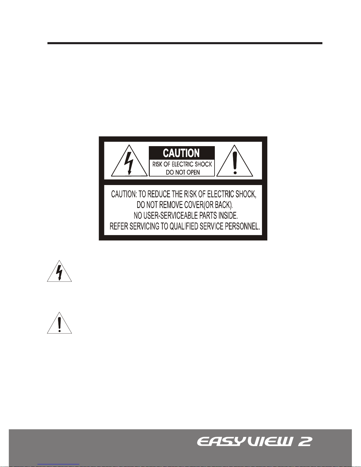
Warning and Caution
The lightning ash with arrowhead symbol, within an equilateral triangle, is intended to
alert the user to the presence of uninsulated “dangerous voltage” within the product’s
enclosure that may be of sufcient magnitude to constitute a risk of electric shock to
persons.
CAUTION!
WARNING!
The exclamation point within an equilateral triangle is intended to alert the user to the
presence of important operating and maintenance (servicing) instruction in the literature
accompanying the product.
Page 4
4
FCC Compliance Statement
CE Compliance Statement
FCC INFORMATION : THIS EQUIPMENT HAS BEEN TESTED AND FOUND TO COMPLY
WITH THE LIMITS FOR A CLASS A DIGITAL DEVICE, PURSUANT TO PART 15 OF THE
FCC RULES. THESE LIMITS ARE DESIGNED TO PROVIDE REASONABLE PROTECTION
AGAINST HARMFUL INTERFERENCE WHEN THE EQUIPMENT IS OPERATED IN A
COMMERCIAL ENVIRONMENT. THIS EQUIPMENT GENERATES, USES, AND CAN RADIATE
RADIO FREQUENCY ENERGY AND IF NOT INSTALLED AND USED IN ACCORDANCE WITH
THE INSTRUCTION MANUAL, MAY CAUSE HARMFUL INTERFERENCE TO RADIO
COMMUNICATIONS. OPERATION OF THIS EQUIPMENT IN A RESIDENTIAL AREA IS
LIKELY TO CAUSE HARMFUL INTERFERENCE IN WHICH CASE THE USER WILL BE
REQUIRED TO CORRECT THE INTERFERENCE AT HIS OWN EXPENSE.
CAUTION : CHANGES OR MODIFICATIONS NOT EXPRESSLY APPROVED BY THE PARTY
RESPONSIBLE FOR COMPLIANCE COULD VOID THE USER’S AUTHORITY TO OPERATE
THE EQUIPMENT.
THIS CLASS A DIGITAL EQUIPMENT COMPLIES WITH CANADIAN ICES-003.
CET APPAREIL NUMÉRIQUE DE LA CLASSE A EST CONFORME À LA NORME NMB-003
DU CANADA.
WARNING : THIS IS A CLASS A PRODUCT. IN A DOMESTIC ENVIRONMENT THIS
PRODUCT MAY CAUSE RADIO INTERFERENCE IN WHICH CASE THE USER MAY BE
REQUIRED TO TAKE ADEQUATE MEASURES
Page 5

5
Important Safeguards
• Read these instructions.
• Heed all warnings.
• Follow all instructions.
• Do not use this equipment near water.
• Clean only with dry cloth.
• Do not block any ventilation openings. Install in accordance with the manufacturer’s
instructions.
• Do not install near any heat sources such as radiators, heat registers, stoves, or other
equipment (including ampliers) that produce heat.
• Do not defeat the safety purpose of the polarized or grounding-type plug. A polarized
plug has two blades with one wider than the other. A grounding type plug has two blades
and a third grounding prong. The wide blade or the third prong is provided for your safety.
If the provided plug does not t into your outlet, consult an electrician for replacement of
the obsolete outlet.
• Protect the power cord from being walked on or pinched, particularly at plugs, convenience receptacles, and the point where they exit from the equipment.
• Only use attachments/accessories specied by the manufacturer.
• Unplug this equipment during lightning storms or when unused for long periods of time.
• Refer all servicing to qualied service personnel. Servicing is required when the equipment has been damaged in any way, such as power-supply cord or plug is damaged,
liquid has been spilled or objects have fallen into the equipment, the equipment has been
exposed to rain or moisture, does not operate normally, or has been dropped.
• CAUTION - THIS MANUAL IS FOR USE BY QUALIFIED SERVICE PERSONNEL ONLY.
TO REDUCE THE RISK OF ELECTRIC SHOCK DO NOT PERFORM ANY SERVICING OTHER
THAN THAT CONTAINED IN THE OPERATING INSTRUCTIONS UNLESS YOU ARE QUALIFIED
TO DO SO.
• Use Certied/Listed Class 2 power supply transformer only.
Page 6

6
Table of Contents
.....................................................................................................
......................................................................................
...........................................................................
...........................................................................
..................................................................................
..........................................................................................
.....................................................................
.....................................................................................
.....................................................................................
......................................................................................
.........................................................................................
............................................................
................................................................................
....................................................
........................................................................
.........................................................................
..................................................................
...................................................
........................................................................
.................................................................
..............................................................................................
.........................................................................................
..........................................................................................
..............................................................
..........................................................................................
....................................................................................
......................................................
........................................................................
...............................................................................................
.........................................................................................
2
3
4
4
5
6
8
9
10
11
12
13
14
15
16
17
18
18
19
19
19
19
19
19
20
20
20
21
21
22
Disclaimer
Warning and Caution
FCC Compliance Statement
CE Compliance Statement
Important Safeguards
Table of Contents
Introduction / Available Models
Content Verication
Parts & Descriptions
Camera Dimensions
Base Installations
Mounting on Electrical Junction Box
Connecting to Monitors
Adjusting the Vari-focal DC Auto Iris Lens
Adjusting the 3-Axis Gimbal
Camera OSD Setup Controls
OSD Menu Control & Navigation
OSD MENU CONTROLS (On-Screen-Display)
OSD Menu Terms & Settings
1. AE SETUP (Automatic Exposure)
1.1 MODE
1.2 CONTROL
1.3 SHUTTER
1.4 AGC (Automatic Gain Control)
1.5 MAX AGC
1.6 BRIGHTNESS
1.7 MAX FIELDS - Digital Slow Shutter
2. WB SETUP (White Balance)
2.1 MODE
2.2 CONTROL
Page 7

7
Table of Contents (Continued)
.....................................................
...................................................................................................
................................................................................................
.......................................................
...............................................................................................
...............................................................................................
......................................
.....................................................................................................
...................................................................................................
...........................................................
........................................................
...........................................................
......................................................................................
........................................................................................
.........................................................................................
...........................................................................
........................................................
..................................................................
...................................................................
......................................................................
.....................................................................
.......................................................
.............................................
...................................
.................................
OSD Menu Terms & Settings (Continued)
2.3 RED
2.4 BLUE
3. BLC SETUP (Back Light Compensation)
3.1 MODE
3.2 LEVEL
3.3 BMB Mode Menu (Brightlight Masking Block)
4. IR ADJ
5. SPECIAL
5.1 MD SETUP (Motion Detection)
5.2 PZM SET (Private Zone Masking)
5.3 DNR (Digital Noise Reduction)
5.4 SHARPNESS
5.5 LANGUAGE
5.6 EDIT TITLE
5.7 FACTORY DEFAULT
EZ-Coax™ (NUVICO Telemetry Control)
Technical Specications | NTSC
Technical Specications | NTSC
Technical Specications | PAL
Technical Specications | PAL
EasyView™ Dome Camera Accessories
Fan & Heater Installation Instructions | CV-FH
Indoor Wall Mount Installation Instructions | CV-WM
Outdoor Wall Mount Installation Instructions | CA-OM
22
22
22
23
23
23
24
25
26
26
27
28
28
28
28
29
30
31
32
33
34
35
36
37
38
Page 8
8
Introduction
Thank you for purchasing our EasyView™2 dome camera.
Our EasyView™2 Dome Cameras are all equipped with high resolution 1/3” Interline
transfer CCD Imager for enhanced low light sensitivity. Combined with our 2nd generation
‘Super Image Enhancer II’ - ‘SIE II’ module, viewing in the dark is radically amplied.
A user-friendly, on-screen display (OSD) menu make it easy to setup and program
functions. Additionally, our EasyView™2 dome camera mounting hardware all come
with pre-drilled holes adaptive to most junction boxes providing installers with effortless
installation.
For EasyView™2 dome camera accessories, please refer to the ‘Accessories’ section in
the back of this manual.
Note: Model numbers with “-CX” attachment indicates cameras equipped with EZ-Coax™.
STD Series 580 TVL •
Day/Night • 34 IR LED
STD Series 580 TVL •
Day/Night
ST Series 580 TVL
Indoor (Plastic)
Outdoor (Vandalproof)
CD-ST21N-I / CD-ST21P-IA(Ivory)
CD-ST21N-B / CD-ST21P-BA (Black)
CD-ST21N-I-CX / CD-ST21P-IA-CX
(Ivory, EZ-Coax) CD-ST21N-B-CX /
CD-ST21P-BA-CX (Black, EZ-Coax)
CD-STD21N-I / CD-STD21P-IA (Ivory)
CD-STD21N-B / CD-STD21P-BA (Black)
CD-STD21N-I-CX / CD-STD21P-IA-CX
(Ivory, EZ-Coax) CD-STD21N-B-CX /
CD-STD21P-BA-CX (Black, EZ-Coax)
CD-STD21N-LI / CD-STD21P-LIA (Ivory)
CD-STD21N-LB / CD-STD21P-LBA (Black)
CD-STD21N-LI-CX / CD-STD21P-LIA-CX
(Ivory, EZ-Coax) CD-STD21N-LB-CX /
CD-STD21P-LBA-CX (Black, EZ-Coax)
Available Models
Accessories
ABOUT THIS MANUAL
CV-ST21N / CV-ST21PA
(Available in ivory housing only)
CV-ST21N-CX / CV-ST21PA-CX
(EZ-Coax, Available in ivory housing only)
CV-STD21N / CV-STD21PA
(Available in ivory housing only)
CV-STD21N-CX / CV-STD21PA-CX
(EZ-Coax, Available in ivory housing only)
CV-STD21N-L / CV-STD21P-LA
(Available in ivory housing only)
CV-STD21N-L-CX / CV-STD21P-LA-CX
(EZ-Coax, Available in ivory housing only)
EasyView™ 2 Catagories
Page 9
9
Content Verication
Before installing the camera, please make sure that all of the following items are
included in the box.
INDOOR ST Series & STD Series
1. EasyView™2 Dome Camera
2. Installation Manual
3. Surface Mount Mounting Template
4. Service Monitor Cable - Model#: CA-SMC30
5. Mounting Hardware
1. EasyView™2 Dome Camera
2. Installation Manual
3. Surface Mount Mounting Template
4. Service Monitor Cable - Model#: CA-SMC30
5. Mounting Hardware
VANDALPROOF ST Series & STD Series
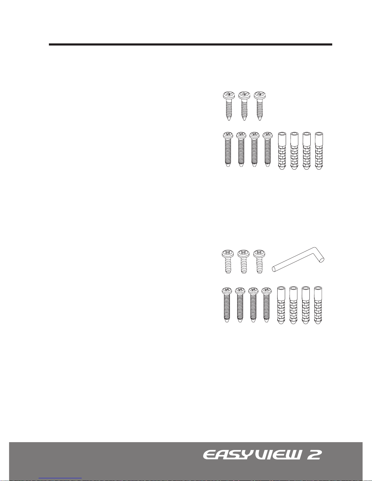
• (x3) Philips ST4x12 Assembly Screws
These screws are used to mount the Flush Mount Base to the Surface Mount Plate.
• (x4) Philips ST4x30 Assembly Screws
These screws are used to mount the Surface Mount Plate to a sturdy surface.
• (x4) Philips ST4x30 Anchors
These anchors are used to fasten the assembly screws securely to the mounting surface.
• (x1) Torx Wrench
• (x3) Philips M4x10 Assembly Screws
These screws are used to mount the Flush Mount Base to the Surface Mount Plate.
• (x4) Philips ST4x30 Assembly Screws
These screws are used to mount the Surface Mount Plate to a sturdy surface.
• (x4) Philips ST4x30 Anchors
These anchors are used to fasten the assembly screws securely to the mounting surface.
Page 10
10
Parts & Descriptions
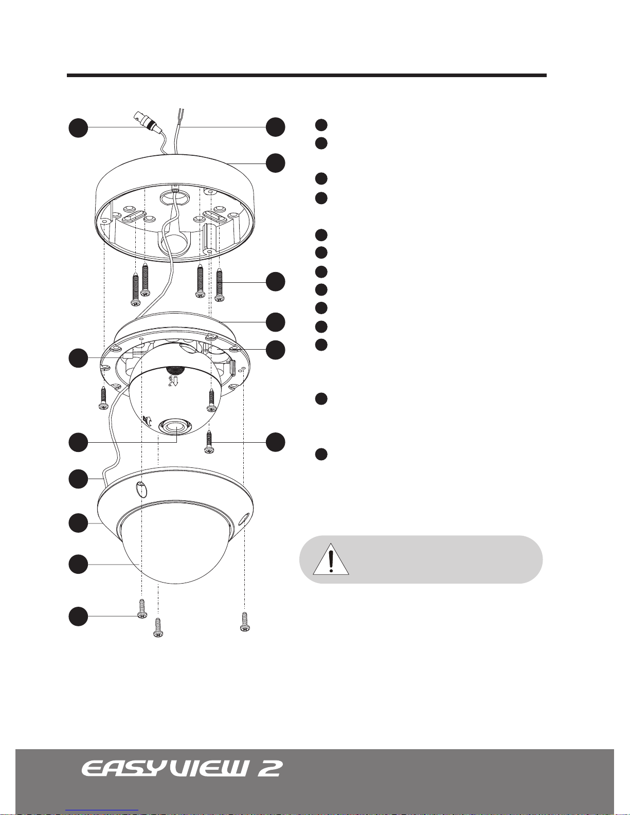
Lens
Power input Connctor
12VDC/24VAC Dual Voltage
Video Output Connector - BNC
Service Monitor Output Connector
Model #: CA-SMC30
Camera Control Board
Safety Wire
Bubble
Dome Cover
Flush Mount Base
Surface Mount Plate
Assembly Screws
Philips M4x9 (Indoor)
Torx M4x9 (Vandalproof)
Assembly Screws
Philips ST4x12 (Indoor)
Philips M4x10 (Vandalproof)
Mounting Screws
Philips ST4x30 (Indoor&Vandalproof)
Note: These assembly screws are located on the
dome cover and not with the mounting hardware.
9
4
5
8
6
1
7
12
11
10
13
3
2
9
4
5
8
6
1
7
12
11
10
13
3
2
For longer, more consistant performance,
avoid location prone to direct sunlight.
REMINDER
Page 11
11
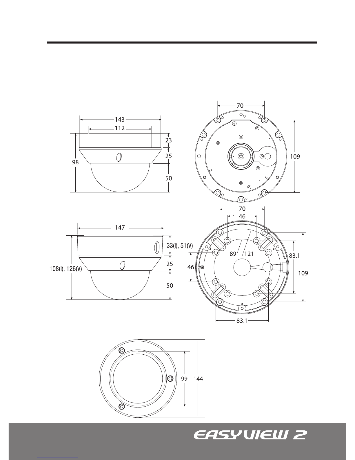
Dimensions Unit: mm
Camera Dimensions
See the diagrams below for the exact dimensions for both the Flush Housing and the Surface
Mount Housing.
NOTE: The Surface Mount Base for all outdoor vandalproof
EasyView™ 2 domes are 51mm and are deeper than the
standard indoor models.
Flush Mount
Top View
Surface Mount (I) Indoor, (V) Vandalproof
Page 12
12
Base Installations
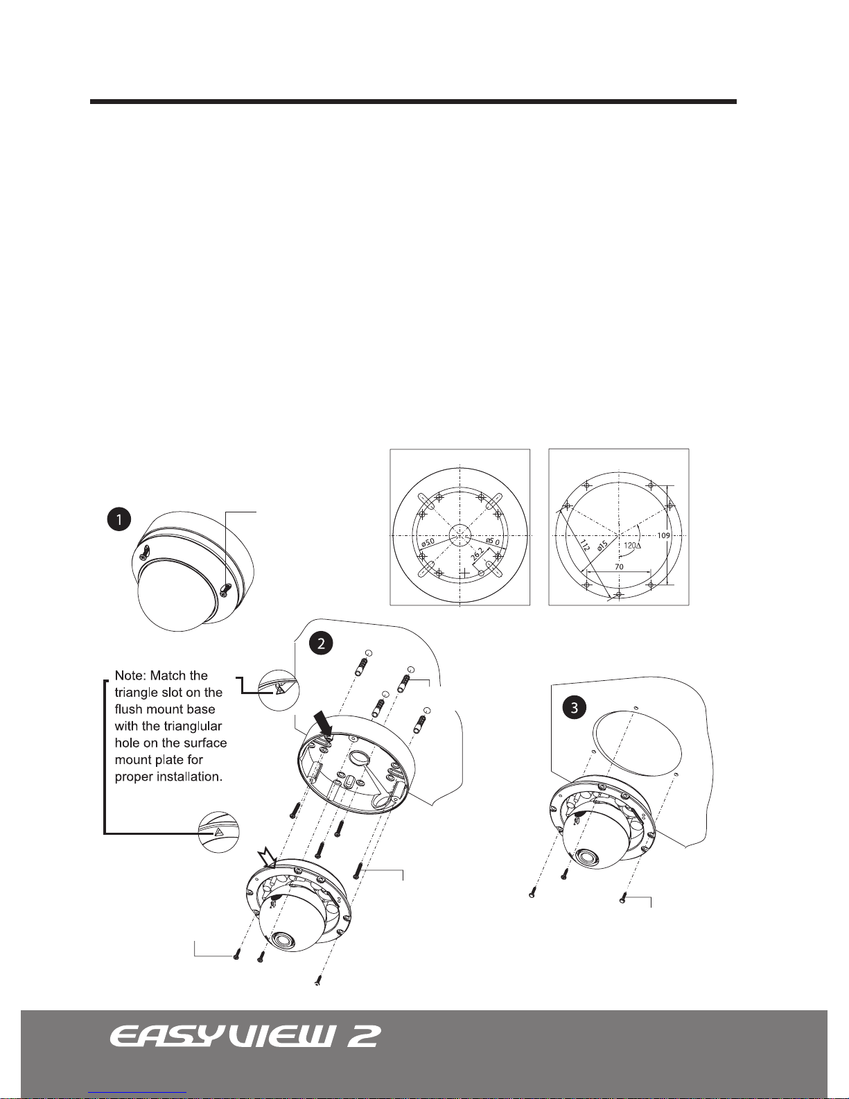
Remove the dome cover by loosening the 3 screws located at the Dome Cover Ring.
EasyView™2 indoor domes use the standard philips screws, while vandal domes
uses the torx screws. Use the Torx Wrench supplied.
Surface Mount
Using four ST4x30 screws provided, mount the surface mount plate to a strudy surface. Using three ST4x12(Indoor) screws, or M4x10(Vandalproof) screws, afx ush
mount base to the surface mount plate.
Flush Mount
Using four ST4x30 screws supplied, mount the surface mount plate to a strudy
surface.
1.
2.
3.
Flush MountSurface Mount
Philips M4X9 or
Trox M4X9
ST4X12 or M4X10
ST4X30
ST4X30
Plastic Anchors
Surface Mount Template
Flush Mount Template
Page 13
13
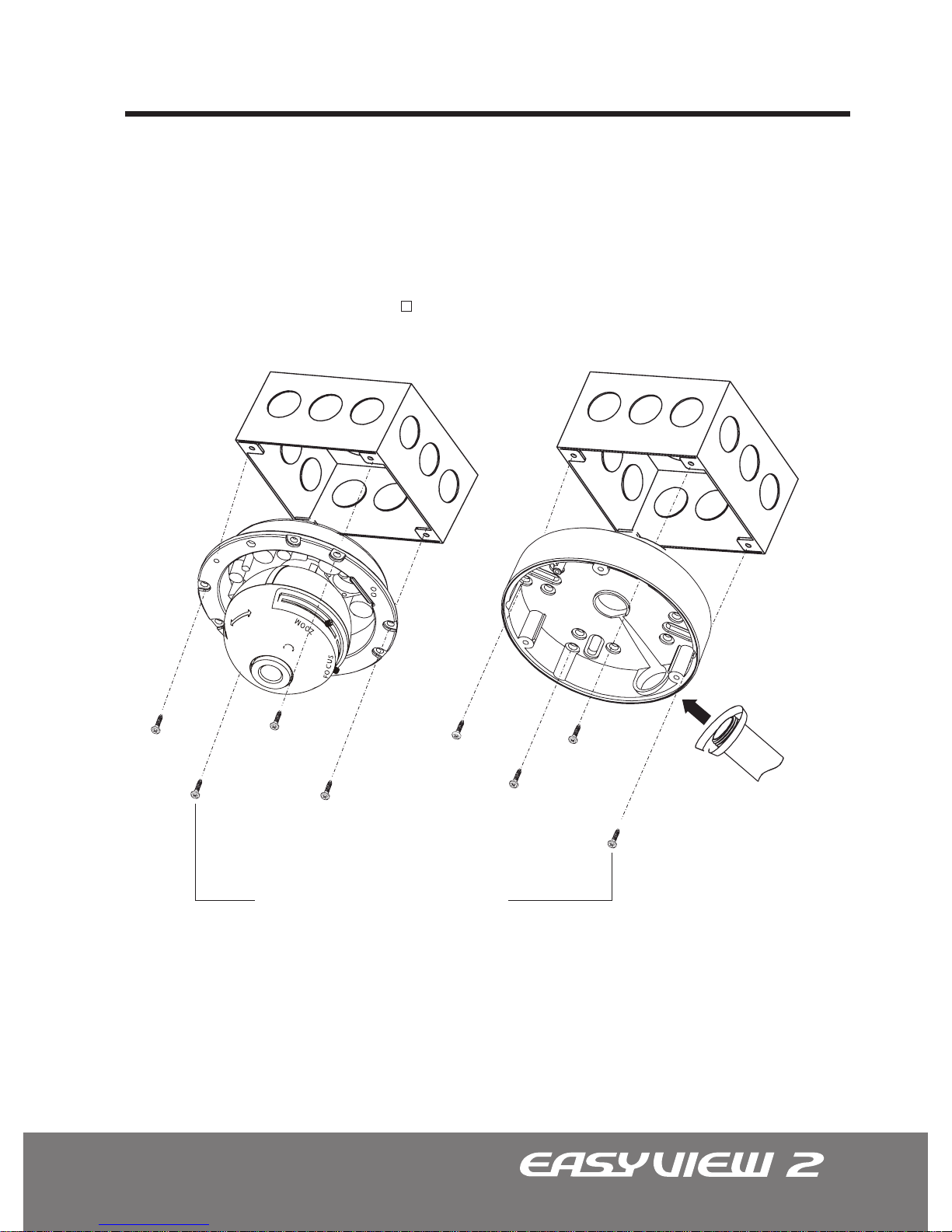
Designed for both ush mount or surface mount applications, pre-drilled mounting holes
on EasyView™ dome accommodate various electrical junction boxes, making installation
easy and less time consuming.
Mounting on Electrical Junction Box
Note: Screws required for electrical junction boxes are not supplied. These screws are
readily available at any well-stocked electrical supply store.
3/4” Pipe
Screws UNC 8-32 x 0.75
When mounting the ush mount base, surface mount plate, or both together, use the
pre-drilled holes marked with the symbol for proper installation.
Page 14
14
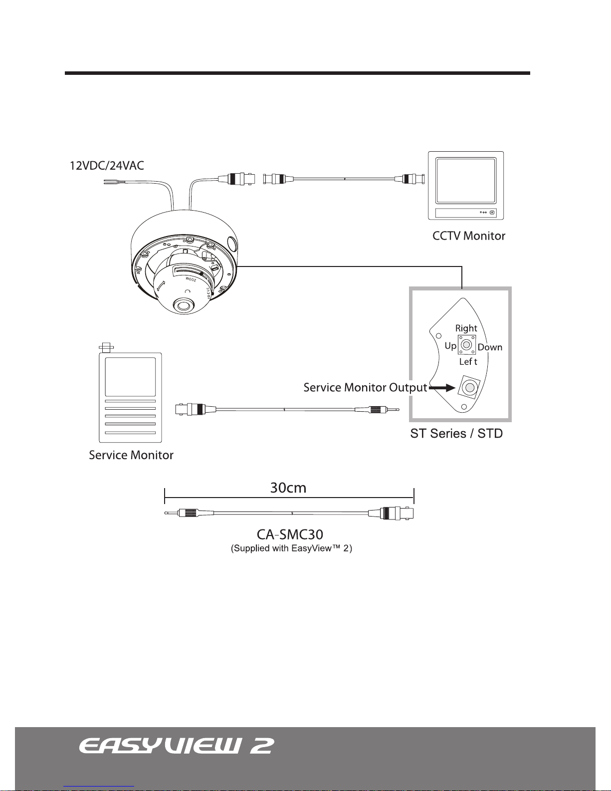
Connecting to Monitors
Follow the diagram below to make proper connections to the CRT Monitor or the Service
Monitor.
• Power connection -12VDC/24VAC Dual Voltage(Auto polarity detection and protection)
• All cameras are equipped with a service monitor output on the camera module.
Page 15
15
1
2
4
5
3
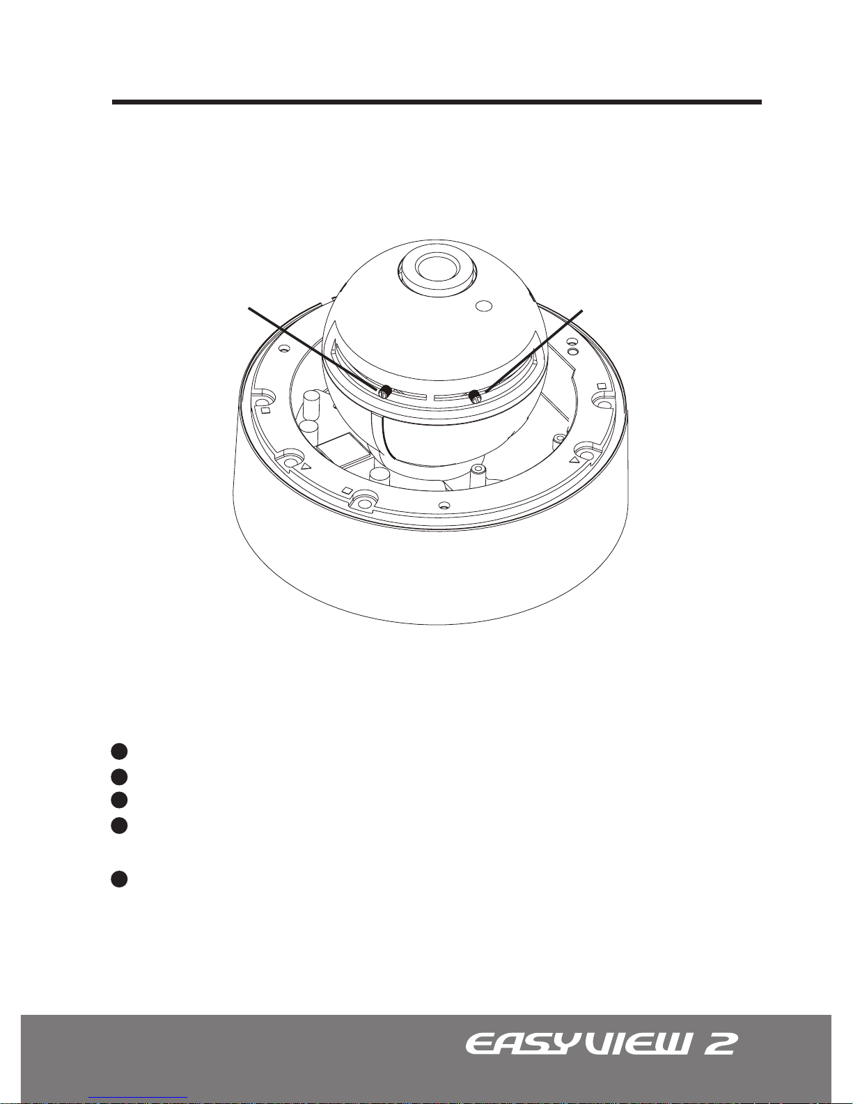
Adjusting the Vari-focal DC Auto Iris Lens
Follow the instruction provided below to make any lens adjustments.
Zoom: Wide ^
-
a Tele
Focus: Far ^
-
a Near
Adjust Angle for Field of View
Adjust Focus
Loosen the Zoom & Focus screws.
Using the screw, move it RIGHT or LEFTto the desired position.
Once the desired adjustments have been made, tighten the screw to lock in place.
Adjust the Field of View by moving the screw towards the RIGHT(Tele) to zoom in, or
towards the LEFT(Wide) to zoom out.
Adjust the Focus the same way as described above after the desired zoom position is
established.
FO
CU
S
ZOOM
Page 16
16
1
2
3
2
3
1
2
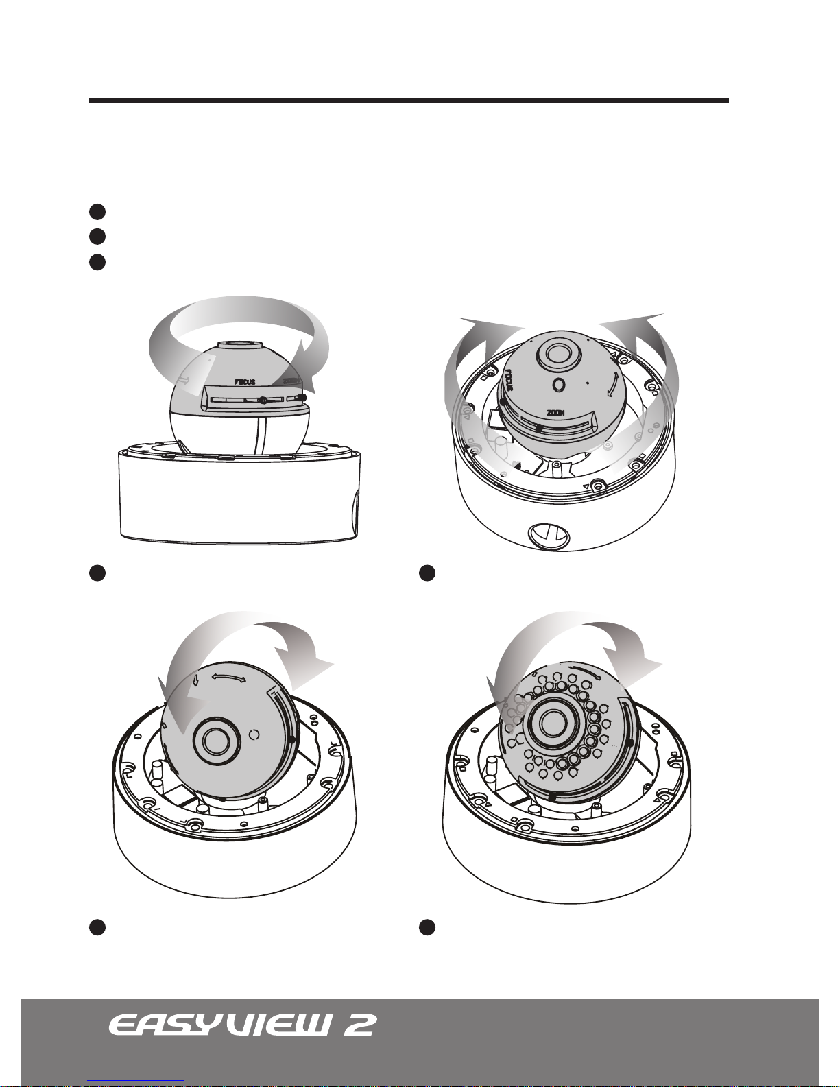
Adjusting the 3-Axis Gimbal
The Gimbal mechanism yields maximum rotation and placement as shown below.
Z-Axis: Rotation 355°
Y-Axis: Tilting 85°/ 75° IR LED
X-Axis: Panning 240°
Tilting 85°
Panning 240°Rotation 355°
Tilting 75° w/ IR LED
Page 17
17
Camera OSD Setup Controls
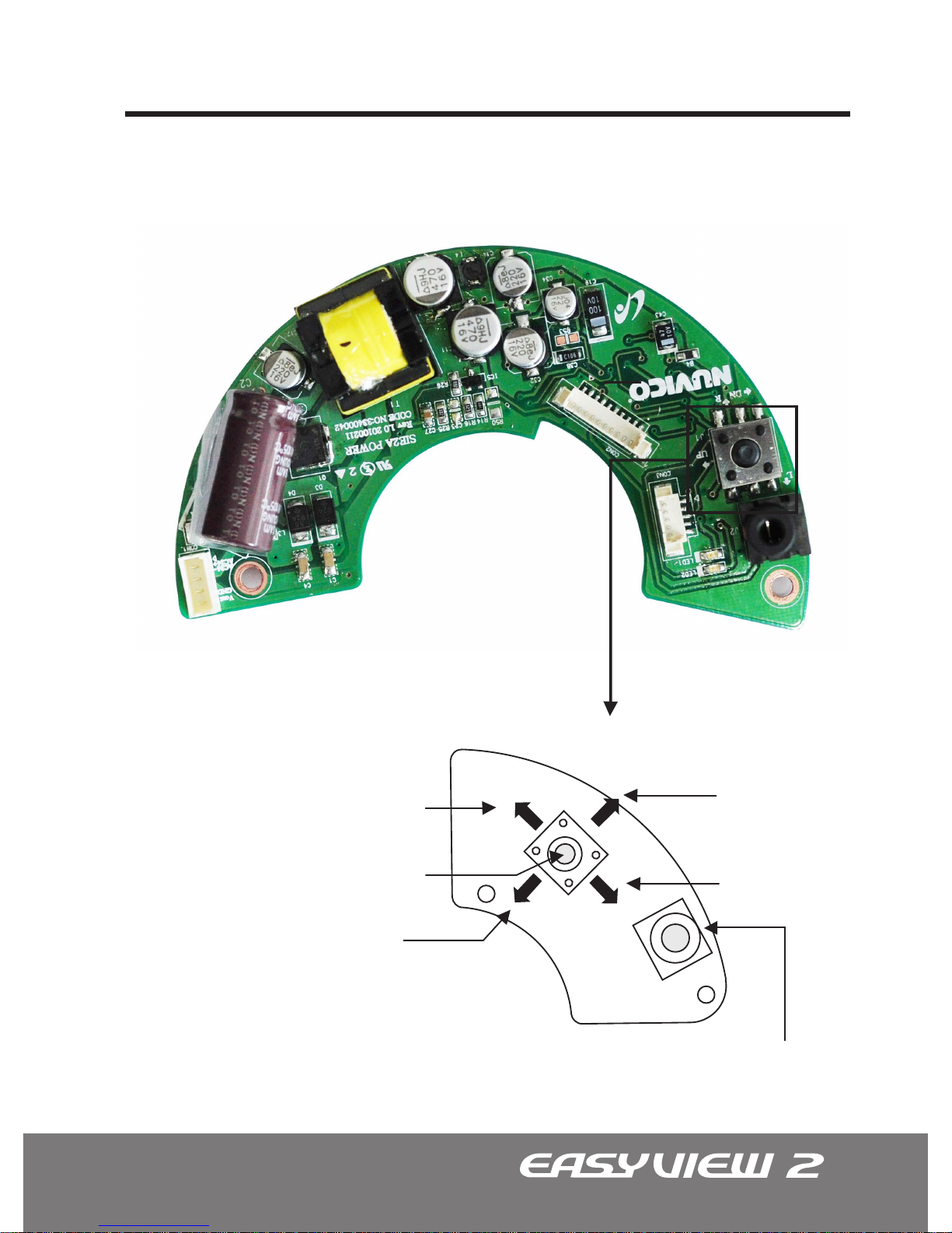
Please use the directional keys located at the bottom of the Gimbal base to make the
desired changes in the OSD menu.
Enter Key
Right Key
Up Key
Down Key
Left Key
Service Monitor Output
Directional Navigation Keys
Page 18
18
OSD Menu Controls & Navigation
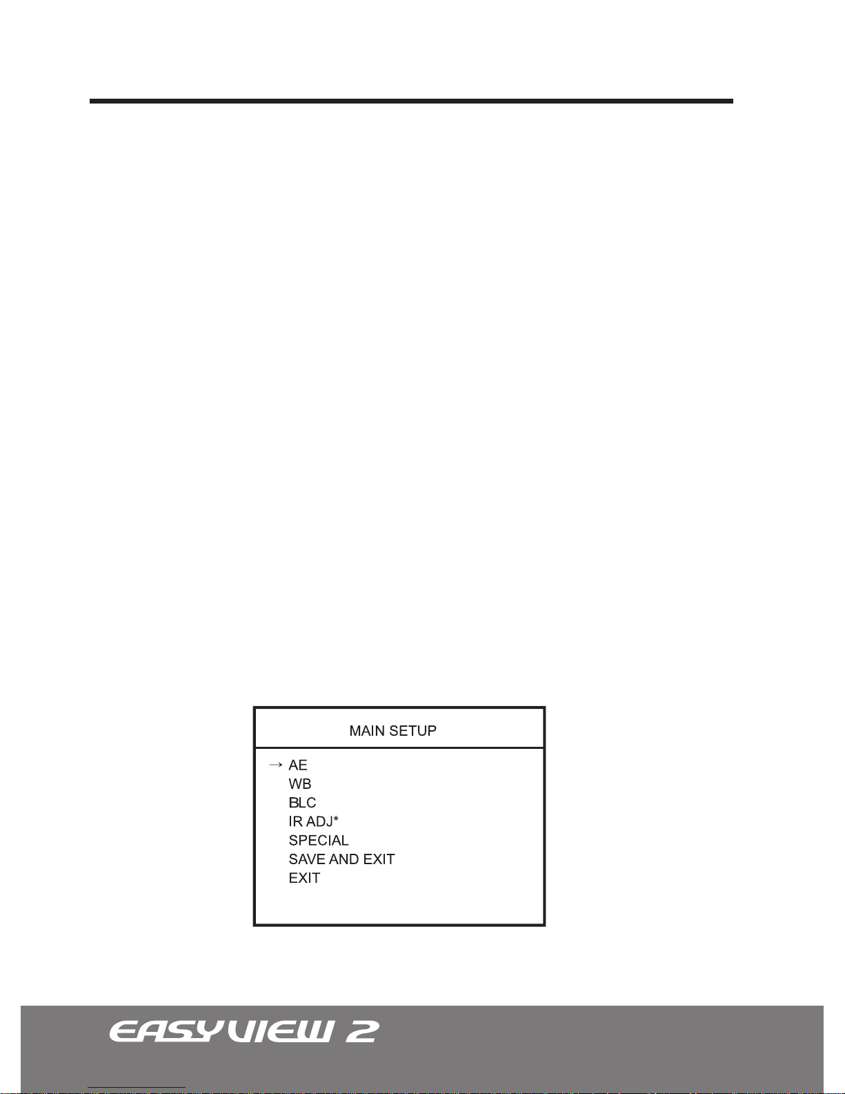
Enter Key - Used to access MAIN SETUP menu mode.
Up / Down Key - Used to scroll through the desired sub-menu selection and to move
the cursor up or down during the OSD menu.
Left / Right Key - Used to adjust the desired menu selection, and to move the cursor
left or right during the OSD menu. Also used to conrm the setting changes.
To enter the main menu, press and hold the ENTER Key down for 2 or more seconds
until the OSD menu appears on the screen.
To enter the sub-menu from the Main menu, press the Left / Right key at the
selected line. While in the OSD menu, scroll up/down the available options by using
the corresponding navigational keys.
To go to the up-menu from the sub- menu, press the Left / Right Key at the
RETURN line.
Once all of the desired changes have been made, move the cursor over to the SAVE
AND EXIT line to save and exit. Choosing EXIT will lose all changes and revert back
to its previously saved conguration.
Note: Asterisk (*) –IR ADJ option is only available with the STD Series Day/Night IR LED
models.
OSD MENU CONTROLS (On-Screen-Display)
Entering and Navigating the Main Menu
Entering and Navigating the Sub-Menu
Go to the Up-Menu from the Sub-Menu
Exiting the OSD Menu
Page 19
19
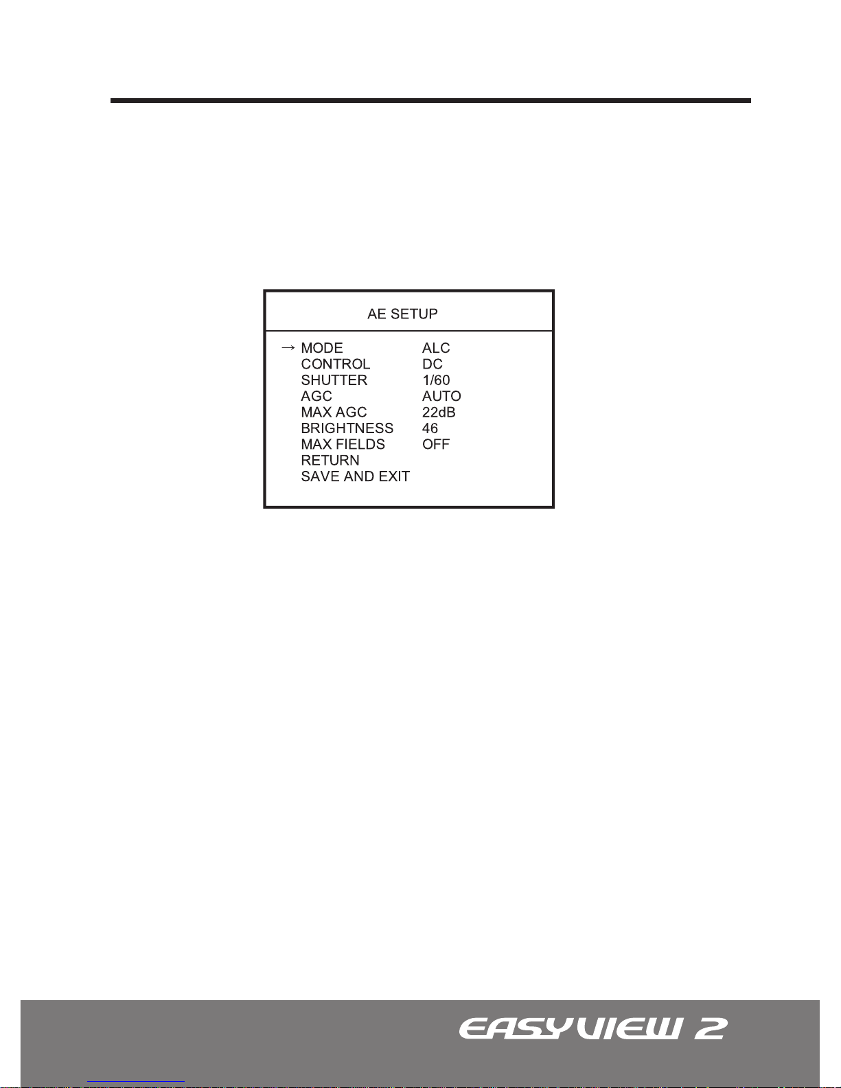
The AE SETUP is used to control the video output levels under different intensities in
the lighting.
1. AE SETUP (Automatic Exposure)
1.1 MODE: ALC (Automatic Level Control)
1.2 CONTROL: DC
1.3 SHUTTER (AUTO, 1/60 ^
-
a 1/100,000)
1.4 AGC - Automatic Gain Control (AUTO, FIXED)
OSD Menu Terms & Settings
The ALC mode and the camera will continuously monitor changes in the lighting
intensity and automatically adjust the Iris to the most optimal level.
All EasyView™ 2 dome cameras are equipped with DC Auto Iris lens.
The SHUTTER speed can be selected manually according to user preference. The
shutter speed of 1/60(NTSC), or 1/50(PAL) seconds are recommended.
Choose between AUTO or FIXED. In the AUTO setting, the AGC will be automatically
controlled. The FIXED setting assumes the MAX AGC value.
Page 20

20
1.5 MAX AGC (OFF, 8dB a ... a36dB)
1.6 BRIGHTNESS (0 ~ 100)
1.7 MAX FIELDS (DSS) - Digital Slow Shutter (OFF, 1FLD a ... a512FLD)
Note: Increasing the MAX FIELDS will also increase the presence of noise.
OSD Menu Terms & Settings
The AGC will compensate the gain levels automatically up to the pre-determined
maximum. The MAX AGC limit can be set as low as 8dB, or as high as 36dB(MAX).
The factory default limit is 22dB.
The BRIGHTNESS can be adjusted by opening and closing of the Iris aperture. User
may ne-tune the screen to their preferred brightness. The brightness ranges from
0~100 - 0 being the darkest, and 100 being the brightest.
In the absence of adequate lighting, DSS allows the ability to capture usable images
without the use of additional illumination. The MAX FLD limit can be set as low as
1FLD, or as high as 512FLD(MAX). The factory default limit is OFF.
Page 21
21
OSD Menu Terms & Settings
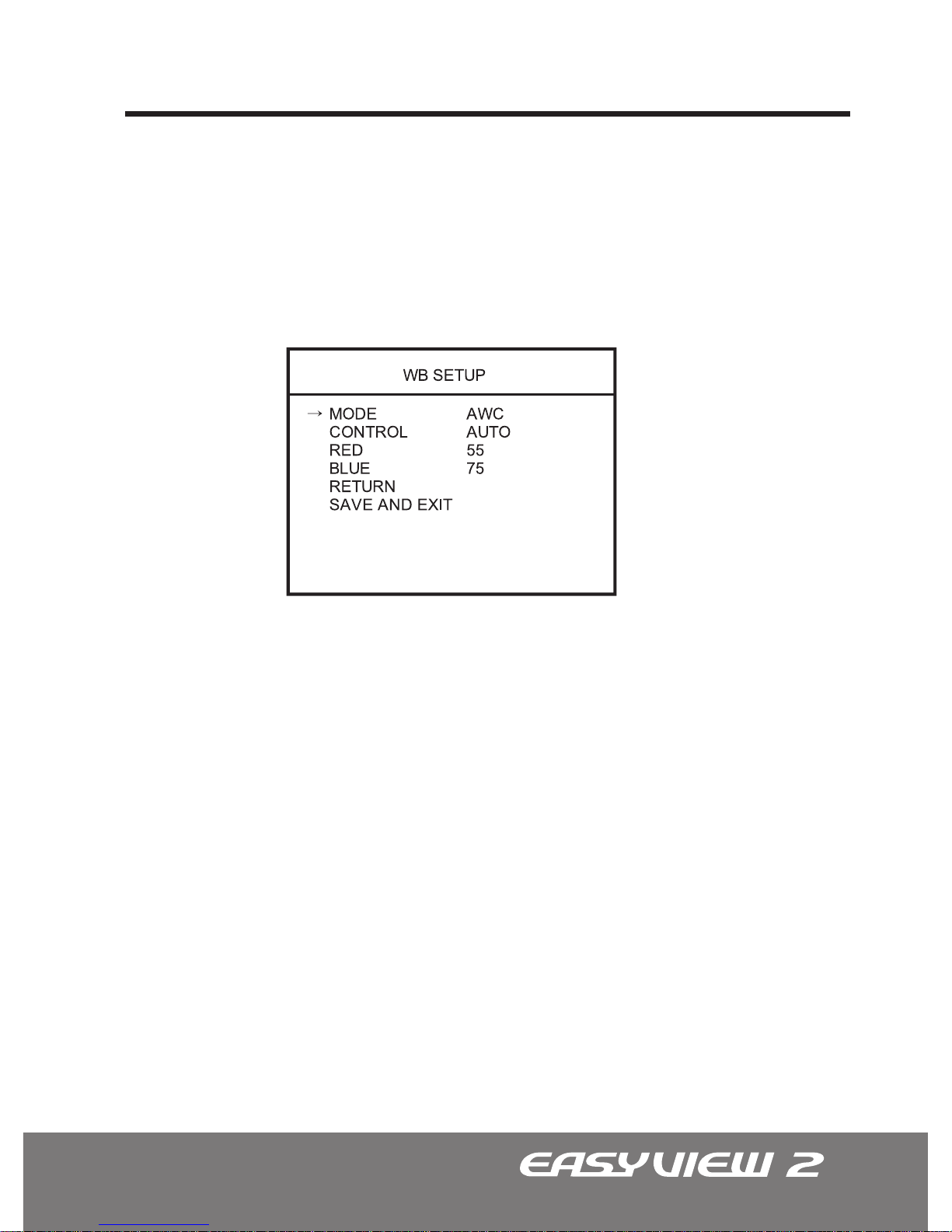
The WB SETUP is used to control the white balance under different illumination sources.
Adjust this setting to calibrate the camera for correct color rendering.
The factory default of ‘AWC AUTO’ is strongly recommended.
2. WB SETUP (White Balance)
2.1 MODE (AWC, ATW, INDOOR, OUTDOOR, MANUAL)
• AWC(Automatic White Balance Control): Choose between the LOCK
mode, AUTO Mode, or the CRLS mode. AUTO mode monitors the color changes and
automatically adjusts the red and blue values to compensate for the color shifting.
LOCK mode locks in the previous color setting and adjusts accordingly. CRLS mode is
used to prevent color-rolling commonly associated with uorescent lighting.
• ATW(Automatic Tracking White Balance): Select the ATW mode if the color
temperature of the light source is between 2,500°K~8,000°K (i.e. Fluorescent Light,
Sodium Vapor Lamps)
• INDOOR: Fixed at 3200°K
• OUTDOOR: Fixed at 5400°K
• MANUAL: Select the MANUAL mode to adjust the RED or BLUE color values
manually.
Page 22

22
OSD Menu Terms & Settings
• This eld displays the current CONTROL status of the WB mode. In the AWC LOCK
mode, the user may control the white balance after pointing the camera to the desired
location. Press Right Key will convert the eld from ‘LOCK’ to ‘PUSH.’ Once the desired
color balance is obtained, press Left Key to lock in the current white balance setting.
2.2 CONTROL - WB Mode Control (LOCK, AUTO, CRLS, 3200°K, 5400°K, R/B CTRL)
2.3 RED (0 ~ 255)
2.4 BLUE (0 ~ 255)
• This eld displays the current RED value of the WB mode. Only in the Manual mode
can the RED value be altered to user preference. The red value ranges from 0~255.
• This eld displays the current BLUE value of the WB mode. Only in the Manual
mode can the BLUE value be altered to user preference. The blue value ranges from
0~255
Page 23
23
OSD Menu Terms & Settings
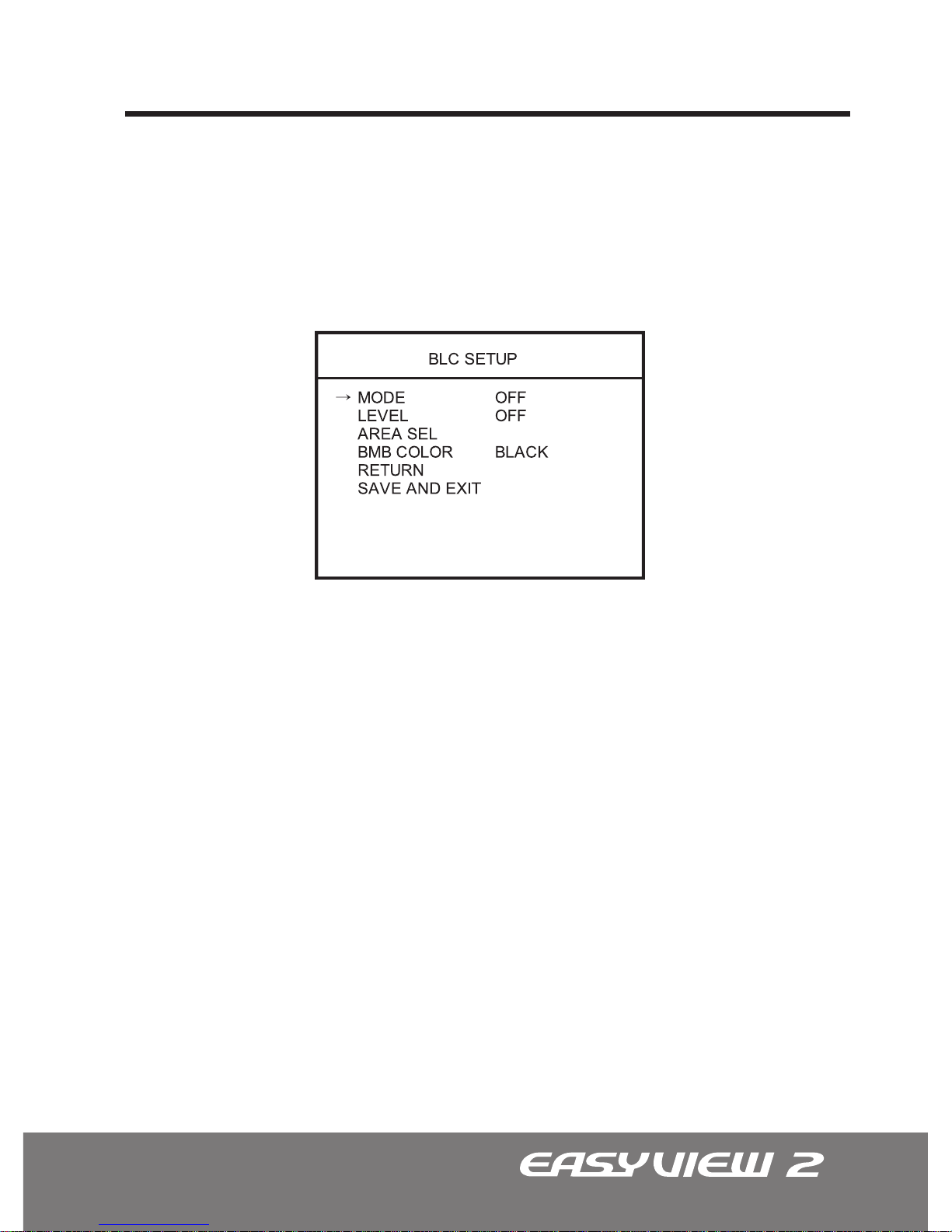
The BLC SETUP is used to control the various Back Light Compensation modes available
in the EasyView™ 2 dome camera. BLC can assist in compensating for exposure problem
associated with very bright backgrounds causing subjects to bloom or silhouette. The
factory default is ‘OFF.’
• OFF: The BLC is off.
• BLC (Back Light Compensation): The BLC divides the frame and calculates each
zone according to its exposure level to counterbalance excessive background light to
distinguish the subject in the foreground.
• SBLC (Super Back Light Compensation)
• BMB (Brightlight Masking Block): The BMB masks out excessively bright areas
within the frame and compensates the rest of the frame
accordingly.
• OFF: The BLC is off.
• BLC: The BLC level can be adjusted from 0~100.
• SBLC: The SBLC level can be adjusted from 0~20.
• BMB: The BMB sensitivity can be adjusted from 0~20.
3. BLC SETUP (Back Light Compensation)
3.1 MODE (OFF, BLC, SBLC, BMB)
3.2 LEVEL (Varies)
Page 24
24
OSD Menu Terms & Settings
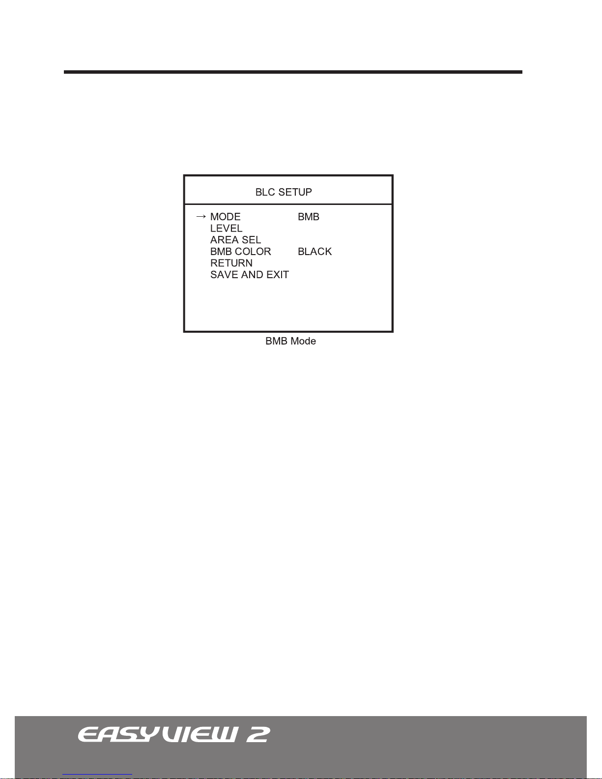
To activate or deactivate specic areas to be masked by BMB, follow the simple
instructions below
3.3 BMB Mode Menu (Brightlight Masking Block)
1. Select the BMB mode, then scroll down to AREA SEL and press the LEFT/RIGHTKey.
2. A blue grid with 16 squares will appear. Choose the desired areas by highlighting
the specic square and pressing the ENTER key (colored in green).
Note: Active masking area is colored in blue.
3. Once all the desired areas have been designated, press and hold the ENTER key
until the AREA MENU displays.
4. Choose the RETURN MENU to conrm the already selected areas, or AREA SELECT
to go back to the blue selection grid.
The BMB masking tint may be changed to user preference in the BMB COLOR option.
• BMB COLOR: (Black -> D. Gray -> L. Gray -> Gray -> White)
10
Page 25
25
OSD Menu Terms & Settings
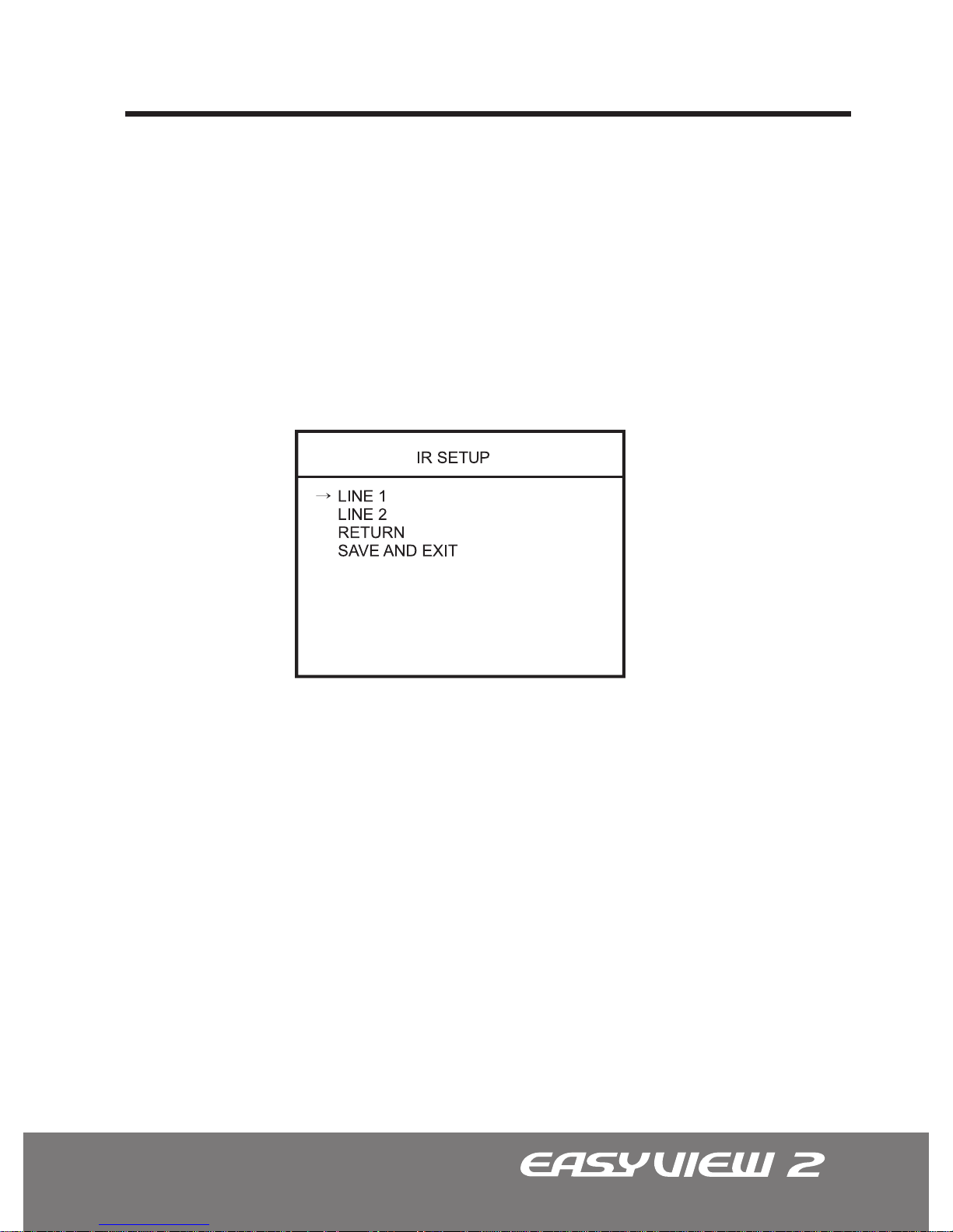
Note: IR ADJ option is only available with the STD Series Day/Night IR LED model.
The IR LED level value ranges from 0 to 10.
• Changes in LINE1 affects the outer LED ring, while changes in LINE2 affects the
inner LED ring.
• At level 0, the IR LEDs will be turned off. The level 10 indicates the maximum IR LED
intensity.
Note: For best result, please adjust the IR LEDs intensity levels while viewing the
changes on a monitor.
This function is used to adjust the intensity of the IR LED. Too much IR reection from a
subject causes over-exposure on the most focused area causing ‘Hot Spots’ within the
picture. Adjusting this setting can help avoid such problems.
4. IR ADJ
IR LED Intensity
10
10
Page 26
26
OSD Menu Terms & Settings
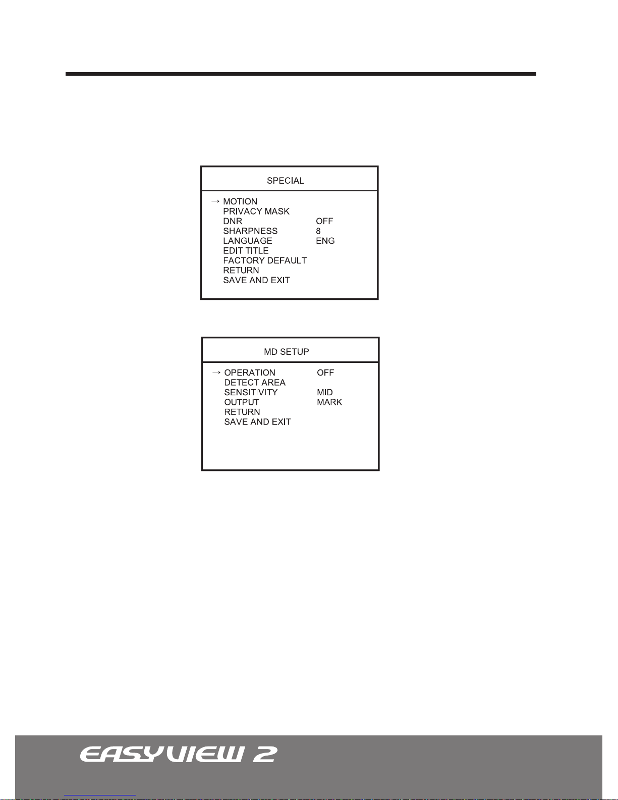
•OPERATION: Select this function ON or OFF. The MD detects motion in area monitored
by the camera.
•DETECT AREA (Area Select): Specic areas of the frame can be selected or monitored
for movement. Please refer to the section on ‘BMB Menu Mode’ for similar programming
instructions.
Note: For the MD selection, the blue grid consists of 64 squares and not 16.
•SENSITIVITY: The user can set the SENSITIVITY of the MOTION DETECTION to one of
three settings. (LOW a MID a HIGH)
•OUTPUT: Select between the MARK or ALARM option. When set to MARK, an icon will
be displayed when Motion Detection is triggered. In the ALARM option, camera will send
out a MD signal.
Note: The EasyView™2 dome camera is not equipped with an MD output port.
Note: The Motion detection will be disabled when DSS is ON.
5. SPECIAL
5.1 MD SETUP - Motion Detection
The Special Setup is used to control the MOTION, PRIVACY MASK, DNR, SHARPNESS,
LANGUAGE, EDIT TITLE, and FACTORY DEFAULT of the dome camera.
Page 27
27
OSD Menu Terms & Settings
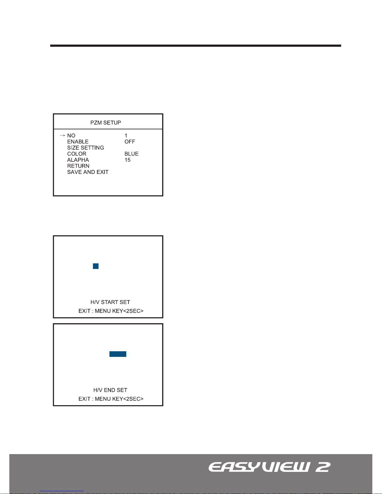
The PZM is used to mask specic areas within the frame of the camera to be
concealed. A total of 8 areas can be masked.
To setup the Privacy Zone masks, follow the
simple instructions below.
1. Select the ZONE NUMBER (1-8), then scroll
down to ENABLE and press the LEFT/RIGHT
Key to turn the ENABLE to ‘ON’ to display the
selected privacy zone mask.
2. Select the SIZE SETTING, then press the LEFT/
RIGHT Key to enter the move screen.
At the H/V START SET option, adjust the width
and height of the area concealed by pressing
LEFT/UP(increasing) or RIGHT/DOWN(decreasing).
At the H/V END SET option, adjust vice versa
by pressing LEFT/UP(decreasing) or RIGHT
DOWN(increasing).
To change H/V START SET option to H/V END SET
and vice versa, press ENTER key. To exit, hold the
ENTER Key down for 2 or more seconds.
3. Change the COLOR and ALPHA (Transparency)
as needed.
4. Repeat steps 1-3 many times as necessary to
conceal all the unwanted areas.
5.2 PZM SET (Private Zone Masking)
Page 28
28
OSD Menu Terms & Settings
The DNR improves picture quality by ltering out signal noise associated with night-time
recording. It compares pictures from a frame with the one previous and removes noise
grains not present before.
• The EasyView™2 dome camera has the ability to digitally sharpen the image to
user preference. The lower setting will soften the image while the higher setting will
sharpen the image.
• English is the factory default and cannot be changed.
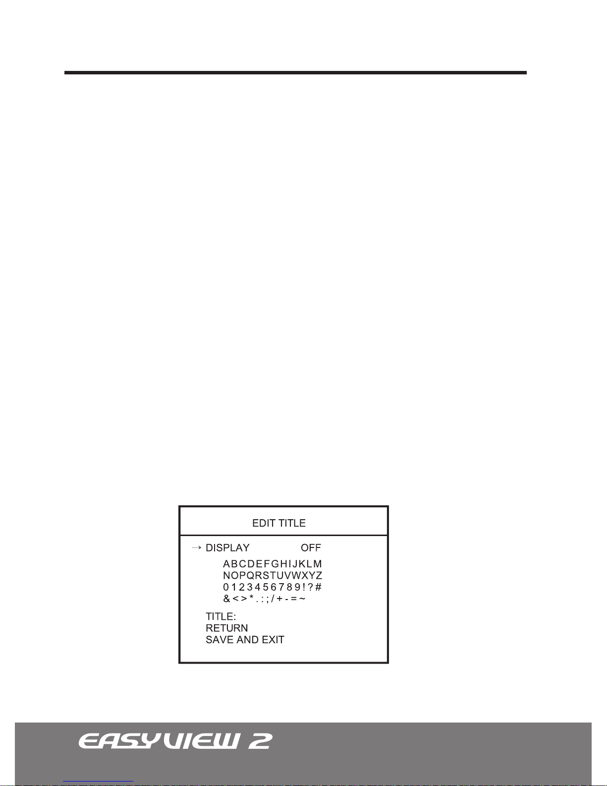
The EDIT TITLE is used to display the camera title.
• OFF: The DNR is off.
• LOW: Select the LOW setting for light level of noise.
• HIGH: Select the HIGH setting for high level of noise.
5.3 DNR - Digital Noise Reduction (OFF, LOW, HIGH)
5.4 SHARPNESS (0 ~ 15)
5.5 LANGUAGE
5.6. EDIT TITLE
Page 29

29
OSD Menu Terms & Settings
1. Select the DISPLAY, then change the setting to “ON” using the LEFT/RIGHT keys.
2. Scroll down to the bottom and input the desired custom title (10-digits MAX). A
custom title may be entered by pressing the ENTER key while highlighting the desired
letter, number, or symbol shown above. The title entered will be displayed in real-time
in the TITLE section.
3. If the default position of the title is undesirable or is hard to see, then the position of
the title can be moved. Scroll to DISPLAY and press the ENTER key to active the title
screen. Move the title to the desired location using the navigational keys. To exit, press
and hold the ENTER key until the EDIT TITLE menu displays.
4. If you want to change the specic character of the title, then select the TITLE. Then
move the highlighting cursor to the desired location using the LEFT/RIGHT keys. Scroll
up to the character table pressing the ENTER key while highlighting the desired letter.
The Factory Default is used to reset all camera settings to the factory default setting.
• FACTORY DEFAULT : If the settings have been altered and the dome camera needs
to be restored to factory default setting, highlight the FACTORY DEFAULT option and
press the LEFT/RIGHT key.
5.7 FACTORY DEFAULT
Page 30
30
EZ-Coax™ (NUVICO Telemetry Control)
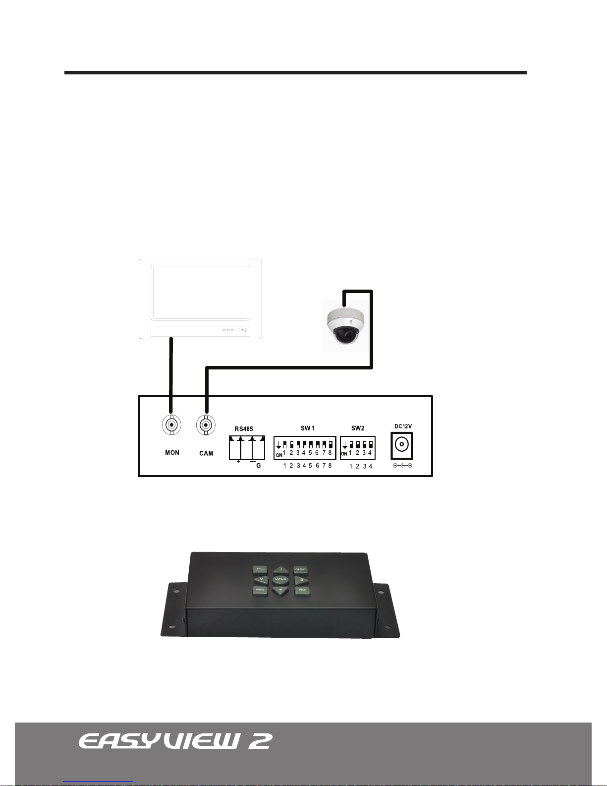
Model numbers with “-CX” attachment indicates cameras equipped with EZ-Coax™.
EZ-Coax™ is the NUVICO up-the-coax telemetry control that grants access to the
EasyView2 OSD menu using only the coax cable already running from the camera.
Refer to the diagram below for a typical EZ-Coax™ transceiver connection conguration,
please refer the EZ-CX1T or EZ-CX8T manual for more information
Page 31
31
Technical Specications | NTSC
IMPORTANT:
All CV Series EasyView™2 Vandalproof Dome Cameras have the same
technical specications as the CD Series indoor dome cameras but has a special
impact resistant dome (IP66) with aluminum housing. The Fan & Heater module does
not come equipped with the CV Series; however can be puchased as an option.
*specifications are subject to change without any prior notice.
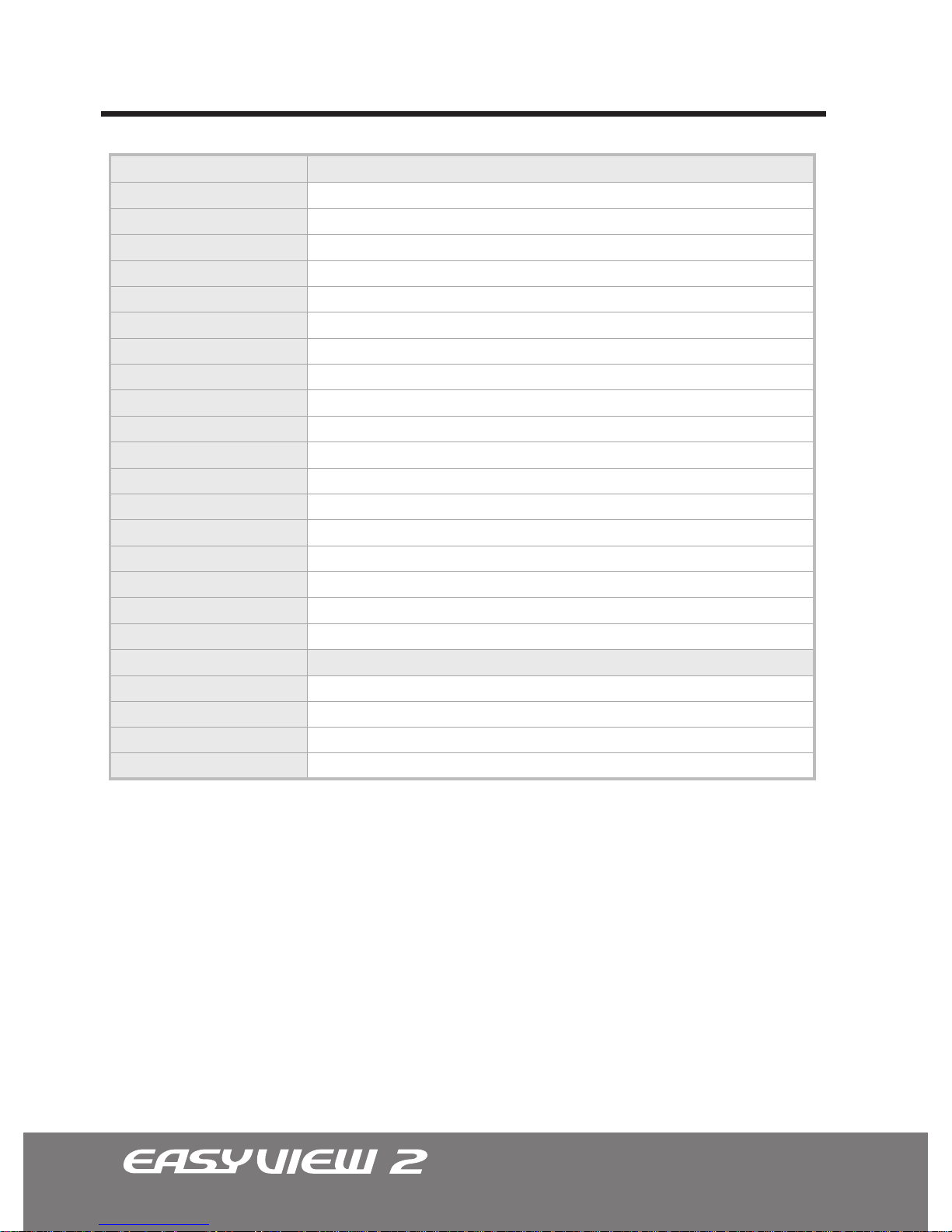
Technical Specifications
Video Format
Image Sensor
Horizontal Resolution
Day / Night Functionality
Lens Type (DC Auto Iris)
Angle of View
Sync System
Effective Pixels (HxV)
Scanning System
Electronic Shutter
Main Video Output
Service Monitor Output
Minimum Illumination (lux)
S/N Ratio
Camera Control & Setup
General Information
Operating Temperature
Operating Humidity
Power Consumption
Input Voltage
CD-ST21N
NTSC
1/3” CCD
580 TV Lines
No
Vari-focal 2.8mm-10mm
131.6°(W) ~ 35.6°(T)
Internal
768 x 494
525 Lines. 2:1 Interlaced
1/60 ~ 1/100,000 sec.
1.0 Vp-p Composite, 75 ohm
1.0 Vp-p Composite, 75 ohm
0.1 (DSS Off), 0.001 (DSS On: x512F)
More than 50dB (AGC Off)
OSD Menu
CD-ST21N
23°F ~ 113°F
Within 90% RH
4W
12VDC/24VAC Dual Voltage
CD-STD21N
NTSC
1/3” CCD
580 TV Lines
Yes w/ ICR
Vari-focal 2.8mm-10mm
131.6°(W) ~ 35.6°(T)
Internal
768 x 494
525 Lines. 2:1 Interlaced
1/60 ~ 1/100,000 sec.
1.0 Vp-p Composite, 75 ohm
1.0 Vp-p Composite, 75 ohm
0.01 (DSS Off), 0.0001 (DSS On: x512F)
More than 50dB (AGC Off)
OSD Menu
CD-STD21N
23°F ~ 113°F
Within 90% RH
4W
12VDC/24VAC Dual Voltage
Page 32
32
Technical Specications | NTSC
*specifications are subject to change without any prior notice.
IMPORTANT : All CV Series EasyView™2 Vandalproof Dome Cameras have the same
technical specications as the CD Series indoor dome cameras but has a special impact
resistant dome (IP66) with aluminum housing. The Fan & Heater module does not come
equipped with the CV Series; however can be puchased as an option.
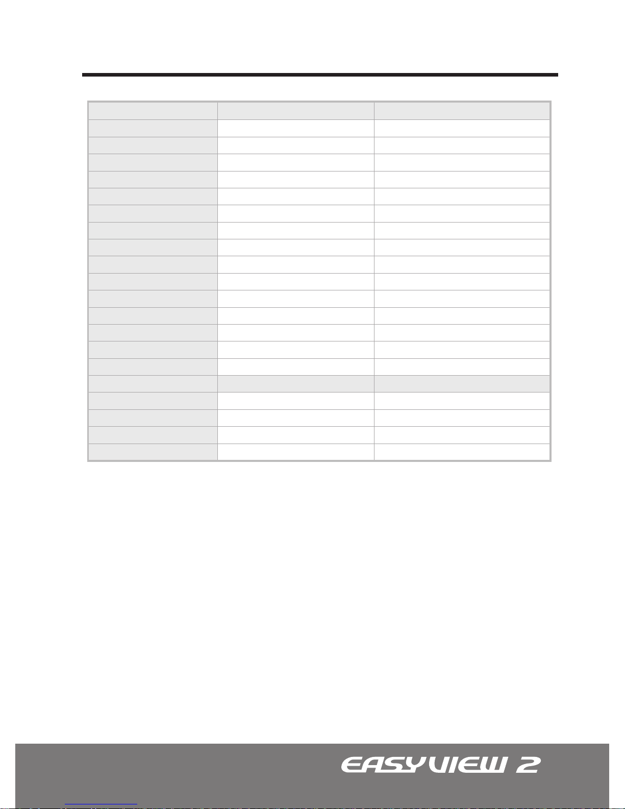
Technical Specifications
Video Format
Image Sensor
Horizontal Resolution
Day / Night Functionality
Lens Type (DC Auto Iris)
Angle of View
IR LED
IR LED Distance
LED Illumination Angle
Sync System
Effective Pixels (HxV)
Scanning System
Electronic Shutter
Main Video Output
Service Monitor Output
Minimum Illumination (lux)
S/N Ratio
Camera Control & Setup
General Information
Operating Temperature
Operating Humidity
Power Consumption
Input Voltage
CD-STD21N-L
NTSC
1/3” CCD
580 TV Lines
Yes w/ ICR
Vari-focal 2.8mm-10mm
131.6°(W) ~ 35.6°(T)
34
Up to 100ft.
80°
Internal
768 x 494
525 Lines. 2:1 Interlaced
1/60 ~ 1/100,000 sec.
1.0 Vp-p Composite, 75 ohm
1.0 Vp-p Composite, 75 ohm
0.01 (DSS Off), 0.0001 (DSS On: x512F)
More than 50dB (AGC Off)
OSD Menu
CD-STD21N-L
23°F ~ 113°F
Within 90% RH
12W (LED On), 4W (Camera Only)
12VDC/24VAC Dual Voltage
Page 33
33
Technical Specications | PAL
IMPORTANT : All CV Series EasyView™2 Vandalproof Dome Cameras have the same
technical specications as the CD Series indoor dome cameras but has a special
impact resistant dome (IP66) with aluminum housing. The Fan & Heater module does
not come equipped with the CV Series; however can be puchased as an option.
*specifications are subject to change without any prior notice.
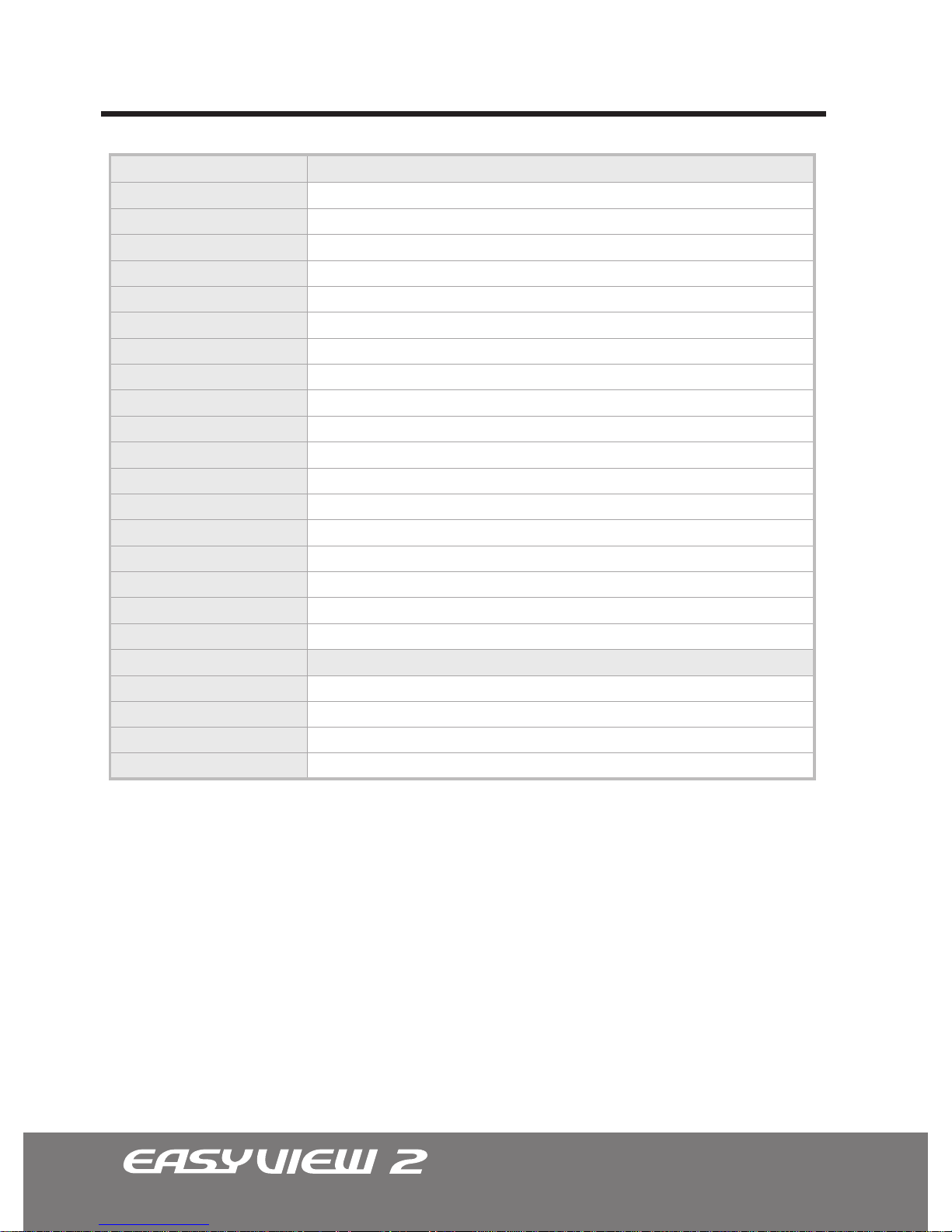
Technical Specifications
Video Format
Image Sensor
Horizontal Resolution
Day / Night Functionality
Lens Type (DC Auto Iris)
Angle of View
Sync System
Effective Pixels (HxV)
Scanning System
Electronic Shutter
Main Video Output
Service Monitor Output
Minimum Illumination (lux)
S/N Ratio
Camera Control & Setup
General Information
Operating Temperature
Operating Humidity
Power Consumption
Input Voltage
CD-ST21PA
PAL
1/3” CCD
580 TV Lines
No
Vari-focal 2.8mm-10mm
131.6°(W) ~ 35.6°(T)
Internal
752 x 582
625 Lines. 2:1 Interlaced
1/50 ~ 1/100,000 sec.
1.0 Vp-p Composite, 75 ohm
1.0 Vp-p Composite, 75 ohm
0.1 (DSS Off), 0.001 (DSS On: x512F)
More than 50dB (AGC Off)
OSD Menu
CD-ST21PA
-5°C ~+45°C
Within 90% RH
4W
12VDC/24VAC Dual Voltage
CD-STD21PA
APAL
1/3” CCD
580 TV Lines
Yes w/ ICR
Vari-focal 2.8mm-10mm
131.6°(W) ~ 35.6°(T)
Internal
752 x 582
625 Lines. 2:1 Interlaced
1/50 ~ 1/100,000 sec.
1.0 Vp-p Composite, 75 ohm
1.0 Vp-p Composite, 75 ohm
0.01 (DSS Off), 0.0001 (DSS On: x512F)
More than 50dB (AGC Off)
OSD Menu
CD-STD21PA
-5°C ~+45°C
Within 90% RH
4W
12VDC/24VAC Dual Voltage
Page 34
34
Technical Specications | PAL
*specifications are subject to change without any prior notice.
IMPORTANT : All CV Series EasyView™2 Vandalproof Dome Cameras have the same
technical specications as the CD Series indoor dome cameras but has a special
impact resistant dome (IP66) with aluminum housing. The Fan & Heater module does
not come equipped with the CV Series; however can be puchased as an option.
Technical Specifications
Video Format
Image Sensor
Horizontal Resolution
Day / Night Functionality
Lens Type (DC Auto Iris)
Angle of View
IR LED
IR LED Distance
LED Illumination Angle
Sync System
Effective Pixels (HxV)
Scanning System
Electronic Shutter
Main Video Output
Service Monitor Output
Minimum Illumination (lux)
S/N Ratio
Camera Control & Setup
General Information
Operating Temperature
Operating Humidity
Power Consumption
Input Voltage
CD-STD21P-LA
PAL
1/3” CCD
580 TV Lines
Yes w/ ICR
Vari-focal 2.8mm-10mm
131.6°(W) ~ 35.6°(T)
34
Up to 100ft.
80°
Internal
752 x 582
625 Lines. 2:1 Interlaced
1/50 ~ 1/100,000 sec.
1.0 Vp-p Composite, 75 ohm
1.0 Vp-p Composite, 75 ohm
0.01 (DSS Off), 0.0001 (DSS On: x512F)
More than 50dB (AGC Off)
OSD Menu
CD-STD21P-LA
-5°C ~+45°C
Within 90% RH
12W (LED On), 4W (Camera Only)
12VDC/24VAC Dual Voltage
Page 35
35
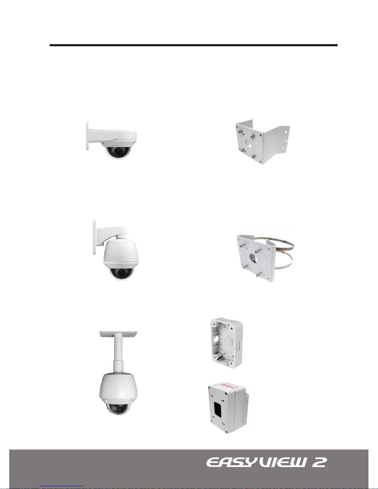
The following are various mounting accesssories available for the EasyView series
dome cameras.
Indoor Wall Mount
| CV-WM
Outdoor Wall Mount
| CA-OM
Pedestal Mount
| CA-PM
Universal Corner Mount Bracket
| CA-CMB
Universal Pole Mount Bracket
| CA-PMB
Junction Box
| CA-JB
Ideal for indoor applications.
Ideal for mounting camera on corners
of a structure.
Ideal for outdooor applications. Used for mounting camera on a pole.
Used for mounting camera on the ceiling.
EasyView™ Dome Camera Accessories
Multipurpose
Junction Box
Enclosure
| CA-JB2
Page 36
36
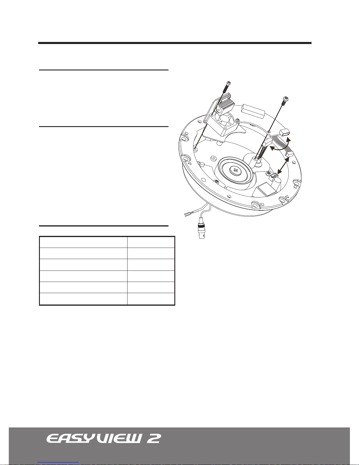
This Fan and Heater assembly is designed for
EasyView™ vandalproof dome camera.
Fan & Heater Installation Instructions | CV-FH
FEATURES
Assembly Accessories
Assembly Screw
Philips M3x6
Q’ty: 1
Length: 6 mm
Thickness: 3 mm
Assembly Screw
Philips M2.6x14
Q’ty: 1
Length: 14 mm
Thickness: 2.6 mm
Specication
Power Input
Power Consumption (Heater)
Power Consumption (Fan)
Heater ON
Heater OFF
Fan ON
24VAC
10W
0.7W
at 41°F (5°C)
at 59°F (15°C)
24 Hours
Note: For Fan and Heater operation, 24VAC
power input is required. Current model does not
support 12VDC operation.
Page 37
37
Indoor Wall Mount Installation Instructions | CV-WM
FEATURES
Assembly Accessories
Note: Mounting
screws are not
supplied with this
package.
Assembly Screws
Philips M4x10
Q’ty: 3
Length: 10 mm
Thickness: 3 mm
Construction
Finish
Weight
Environment
Aluminum
Ivory or Black
1.4 lb (0.64Kg)
Indoor Only
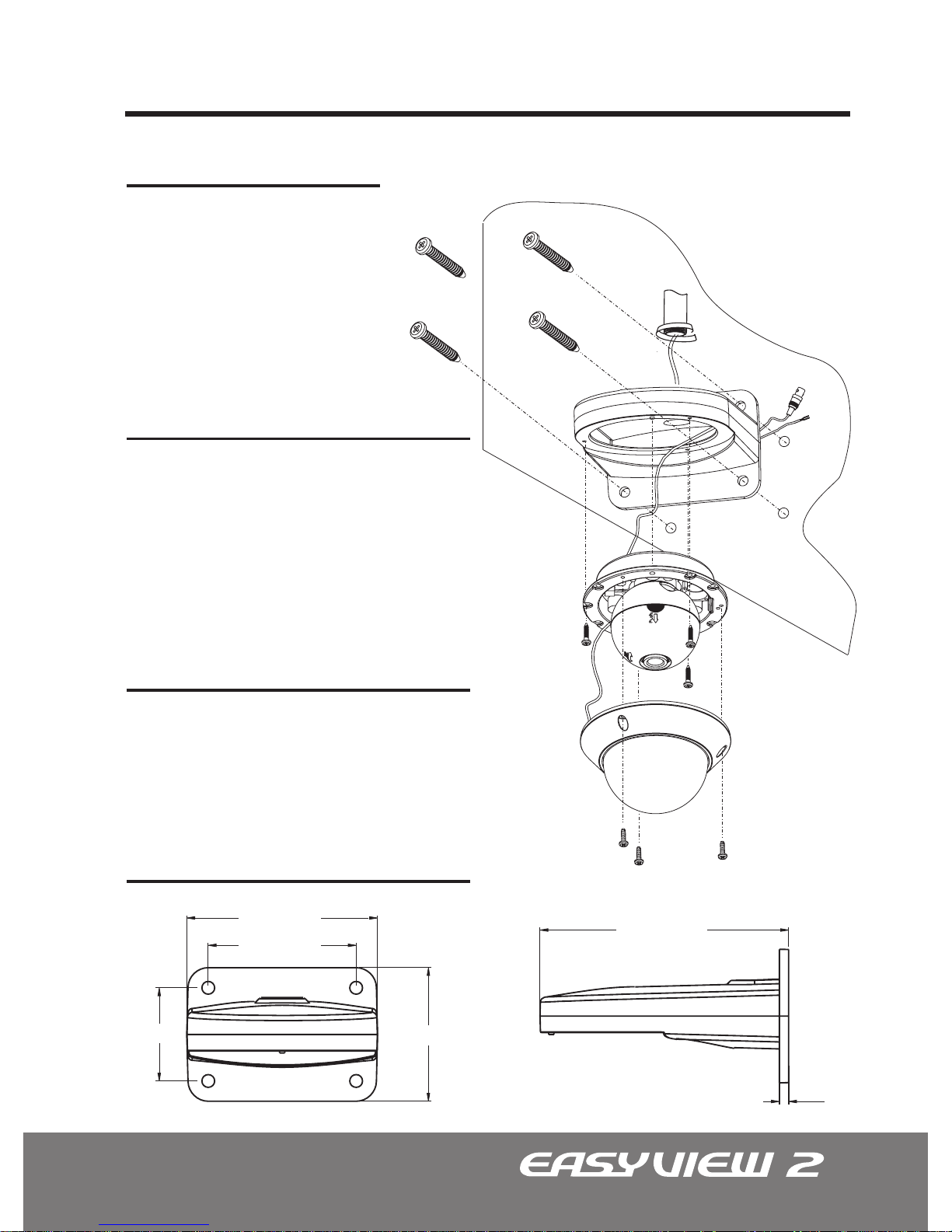
This indoor wall mount is
designed for EasyView™ dome
camera . This mount can be
directly to a wall or attached to a
junction box (CA-JB).
Specication
Dimensions Unit: Inch (mm)
5.64” (143.4)
4.37” (111.2)
2.75” (70)
3.95” (100.4)
7.36” (187)
0.28” (7)
Page 38
38
Outdoor Wall Mount Installation Instructions | CA-OM
FEATURES
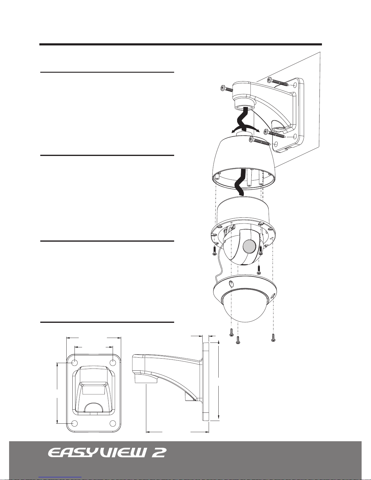
This outdoor wall mount is designed for
EasyView™ dome camera and the EasyTrak™
MIni PTZ camera. This mount can be directly to
a wall or attached to a junction box (CA-JB).
Assembly Accessories
Anchors
Plastic
Q’ty: 4
Length: 35 mm
Thickness: 7 mm
Mounting Screw
Philips ST5x35
Q’ty: 4
Length: 35 mm
Thickness: 5 mm
Specication
Aluminum
Light-gray or Black
polyester powder coat.
45 lb (20Kg)
Indoor/Outdoor
Construction
Finish
Max. Load
Environment
Dimensions Unit: Inch (mm)
4.33” (110)
3.44” (100)
2.75” (70)
4.53” (115)
5.63” (143)
0.47” (12)
Page 39

39
Page 40
050600003600
 Loading...