

Page 1
Page 2

Disclaimer
• While every effort has been made to ensure that the information contained in this guide
is accurate and complete, no liability can be accepted for any errors or omissions.
• NUVICO reserves the right to change the specifications of the hardware and software
described herein at any time without prior notice.
• No part of this guide may be reproduced, transmitted, transcribed, stored in a retrieval
system, or translated into any language in any form, by any means, without prior written
permission of NUVICO.
• NUVICO makes no warranties for damages resulting from corrupted or lost data due to a
mistaken operation or malfunction of the cameras, peripheral devices, or unapproved/un
supported devices.
2
Page 3
Warning and Caution
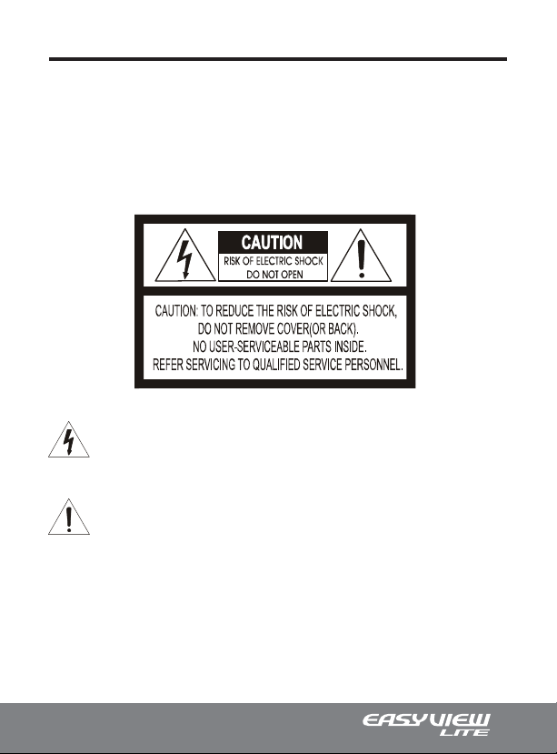
WARNING!
TO REDUCE THE RISK OF FIRE OR ELECTRIC SHOCK, DO NOT EXPOSE THIS PRODUCT
TO RAIN OR MOISTURE. DO NOT INSERT ANY METALLIC OBJECTS THROUGH THE
VENTILATION GRILLS OR OPENINGS ON THE EQUIPMENT.
CAUTION!
The lightning flash with arrowhead symbol, within an equilateral triangle, is intended to
alert the user to the presence of uninsulated “dangerous voltage” within the product’s
enclosure that may be of sufficient magnitude to constitute a risk of electric shock to
persons.
The exclamation point within an equilateral triangle is intended to alert the user to the
presence of important operating and maintenance (servicing) instruction in the literature
accompanying the product.
3
Page 4

Important Safeguards
• Read these instructions.
• Heed all warnings.
• Follow all instructions.
• Do not use this equipment near water.
• Clean only with dry cloth.
• Do not block any ventilation openings. Install in accordance with the manufacturer’s
instructions.
• Do not install near any heat sources such as radiators, heat registers, stoves, or other
equipment (including amplifiers) that produce heat.
• Do not defeat the safety purpose of the polarized or grounding-type plug. A polarized
plug has two blades with one wider than the other. A grounding type plug has two blades
and a third grounding prong. The wide blade or the third prong is provided for your safety. If
the provided plug does not fit into your outlet, consult an electrician for replacement of the
obsolete outlet.
• Protect the power cord from being walked on or pinched, particularly at plugs, convenience receptacles, and the point where they exit from the equipment.
• Only use attachments/accessories specified by the manufacturer.
• Unplug this equipment during lightning storms or when unused for long periods of time.
• Refer all servicing to qualified service personnel. Servicing is required when the equipment has been damaged in any way, such as power-supply cord or plug is damaged,
liquid has been spilled or objects have fallen into the equipment, the equipment has been
exposed to rain or moisture, does not operate normally, or has been dropped.
• CAUTION - THIS MANUAL IS FOR USE BY QUALIFIED SERVICE PERSONNEL ONLY. TO
REDUCE THE RISK OF ELECTRIC SHOCK DO NOT PERFORM ANY SERVICING OTHER THAN
THAT CONTAINED IN THE OPERATING INSTRUCTIONS UNLESS YOU ARE QUALIFIED TO DO
SO.
• Use Certified/Listed Class 2 power supply transformer only.
4
Page 5

Table of Contents
Disclaimer
Warning and Caution
Important Safeguards
Table of Contents
Introduction / Available Models
Content Verification
Parts & Descriptions
Camera Dimensions
Base Installations
Connecting to Monitors
Adjusting the Vari-focal DC Auto Iris Lens
Adjusting the 3-Axis Gimbal
Opening the 3-Axis Gimbal Cover
Switching OFF/ON the IR LED
Dip Switch Functions and Operations
Dip Switch Menu Control Terms
A. ICR Switch Time
B. FLK Mode
C. BLK
D. White Balance (ATW/AWC)
Technical Specifications
CD-H2N / CD-HD39N | NTSC
CD-HD2N-L / CD-HD39N-L | NTSC
CD-H2P / CD-HD39P | PAL
CD-HD2P-L / CD-HD39P-L | PAL
Memo & Notes
..............................................................................................
.............................................................................
............................................................................
...................................................................................
............................................................
...............................................................................
..............................................................................
...............................................................................
..................................................................................
.........................................................................
...................................................................
..........................................................
...............................................................
................................................................................
........................................................................................
.................................................................................................
................................................................
................................................................
........................................................
...................................................................
...........................................................
.......................................................................................
...........................................
..................................................
2
3
4
5
6
7
8
9
10
11
12
13
14
15
16
17
17
17
17
18
19
20
21
22
5
Page 6
Introduction
ABOUT THIS MANUAL
Thank you for purchasing our EasyView™ Lite dome camera.
Our EasyView™ Lite Dome Cameras are all equipped with high resolution 1/3” Interline
transfer CCD Imager for enhanced lowlight sensitivity. Available in a host of different
combinations, from standard fixed lens indoor color domes, to vari-focal day/night
vandalproof dome, EasyView™ Lite series cameras accommodate a broad range of
applications and demanding environments.
Before installing and using this camera, please read this manual fully and carefully,
and be sure to keep it handy for later use. This installation manual covers the following
models listed below. Any difference in features are indicated where necessary.
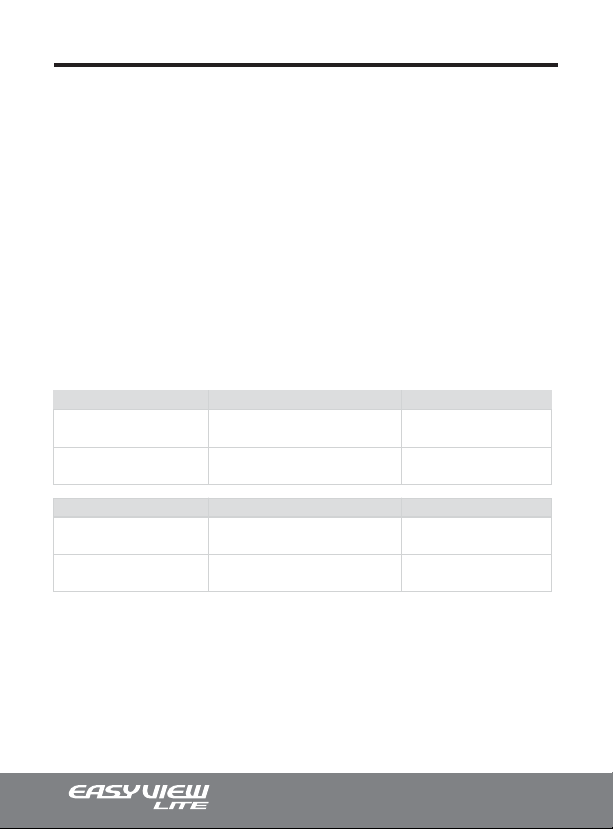
Available Models
FIXED LENS
H Series
550 TVL
HD Series
550 TVL • Day/Night • 18 IR LED
INDOOR DOME VANDALPROOF DOME
CD-H2N-I / CD-H2P-I (Ivory)
CD-H2N-B / CD-H2P-B (Black)
CD-HD2N-LI / CD-HD2P-LI (Ivory)
CD-HD2N-LB / CD-HD2P-LB (Black)
CV-H2N / CV-H2P
Available in ivory housing only.
CV-HD2N-L / CV-HD2P-L
Available in ivory housing only.
VARI-FOCAL LENS
H Series
550 TVL
HD Series
550 TVL • Day/Night • 16 IR LED
6
INDOOR DOME VANDALPROOF DOME
CD-H39N-I / CD-H39P-I (Ivory)
CD-H39N-B / CD-H39P-B (Black)
CD-HD39N-LI / CD-HD39P-LI (Ivory)
CD-HD39N-LB / CD-HD39P-LB (Black)
CV-H39N / CV-H39P
Available in ivory housing only.
CV-HD39N-L / CV-HD39P-L
Available in ivory housing only.
Page 7
Content Verification
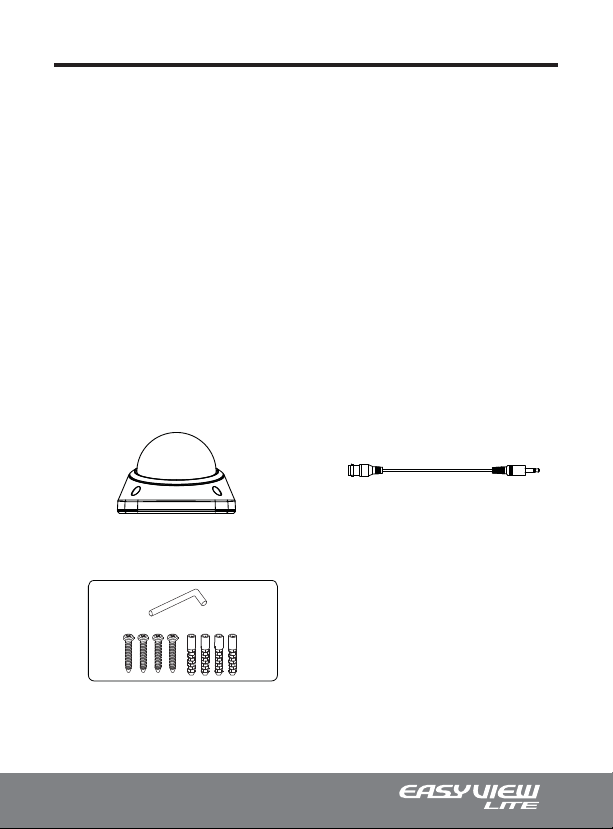
Before installing the camera, please make sure that all of the following items are
included in the box.
EasyView™ Lite Dome CAMERA
1. EasyView™ Lite Dome Camera
2. Installation Manual
3. Surface Mount Mounting Template
4. Service Monitor Cable - Model#: CA-SMC30
(Vari-focal Lens models only)
5. Mounting Hardware
• (x1) Torx Wrench (Vandalproof Only)
• (x4) Philips ST4x30 Assembly Screws
These screws are used to mount the Surface Mount Plate to a sturdy surface.
• (x4) Philips ST4x30 Anchors
These anchors are used to fasten the assembly screws securely to the mounting surface.
EasyView™ Lite Dome Camera Service Monitor Cable
(CA-SMC30)
Assembly & Mounting Accessories
7
Page 8
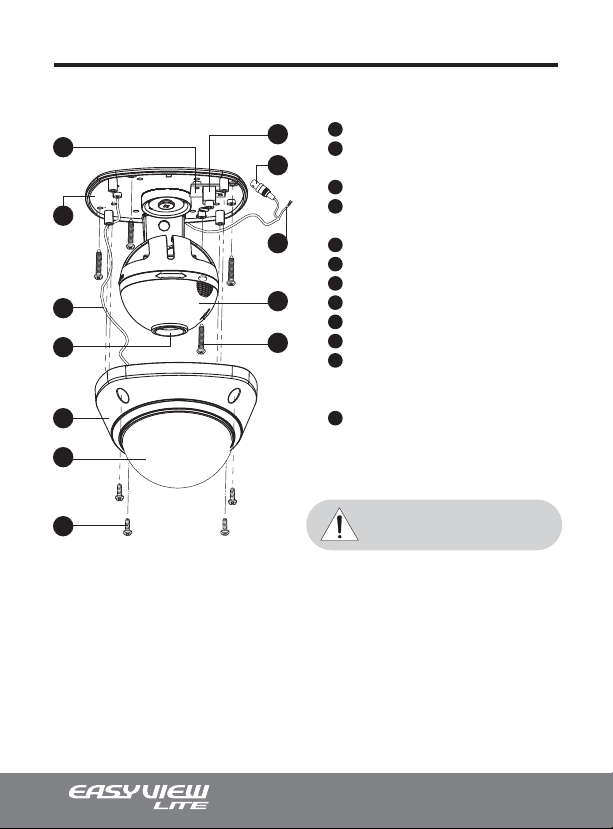
Parts & Descriptions
5
10
6
1
8
7
11
Note: These assembly screws are located on the
dome cover and not with the mounting hardware.
1
4
3
2
9
12
Lens
2
Power input Connctor
12VDC/24VAC Dual Voltage (Vari-focal Only)
3
Video Output Connector - BNC
4
Service Monitor Output Connector
Model #: CA-SMC30 (Vari-focal Only)
5
Camera Power Board (Vari-focal Only)
6
Safety Wire
7
Bubble
8
Dome Cover
9
Camera Module
10
Surface Mount Plate
11
Assembly Screws
Philips M3x12 (Indoor)
Torx M4x11 (Vandalproof)
12
Mounting Screws
Philips ST4x30 (Indoor & Vandalproof)
REMINDER
For longer, more consistant performance, avoid
installation locations prone to direct sunlight.
8
Page 9
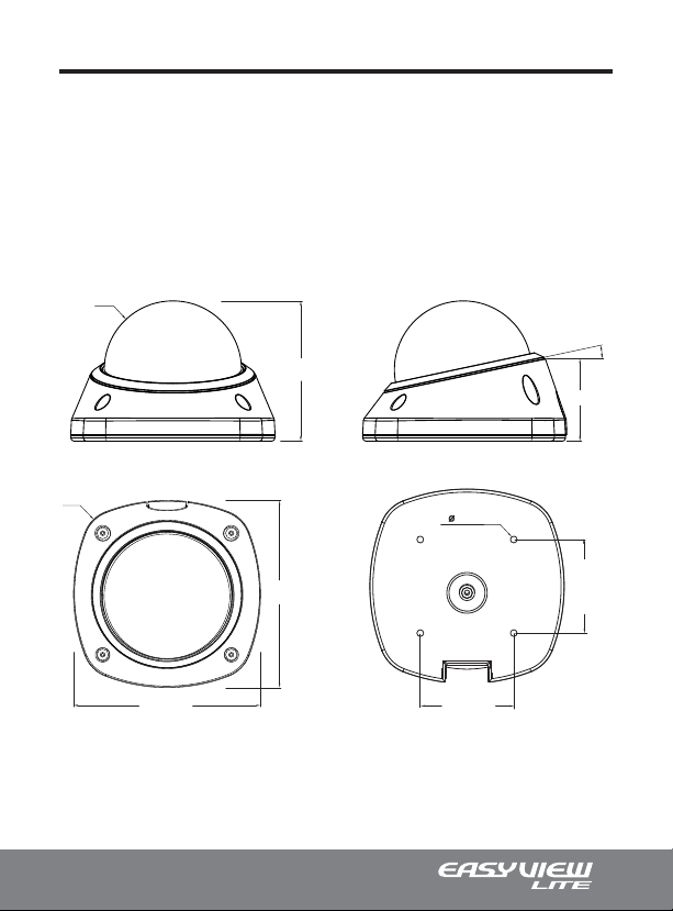
Camera Dimensions
EasyView™ Lite dome camera housing is specially designed allowing for additional 12°
tilt of the 3-Axis Gimbal. Even at full 90° tilt, the view out of the EasyView™ Lite will be
unobstructed. See the diagrams below for the exact dimensions of the EasyView™ Lite
dome camera.
Dimensions Unit: Inches (mm)
R44,0
1
3.54” (90)
2.09” (53)
˚
2
yY\
\UX] OXZXP
\UX] OXZXP
GG[T
GG[U\Go
YU[_GO]ZP
GO]ZP
U[_
Y
9
Page 10

Base Installations
Remove the dome cover by loosening the 4 screws located at the Dome Cover
1.
Ring. EasyView™ Lite indoor domes use the standard philips screws, while vandal
domes uses the torx screws. Use the Torx Wrench supplied.
Using four ST4x30 screws provided, mount the surface mount plate to a strudy
2.
surface. Using four M3x12(Indoor) screws, or M4x11(Vandalproof) screws, affix the
dome cover back on to the surface mount plate.
10
2
1
z{[ZW
wGtZXYG
{Gt[XX
wGh
Page 11
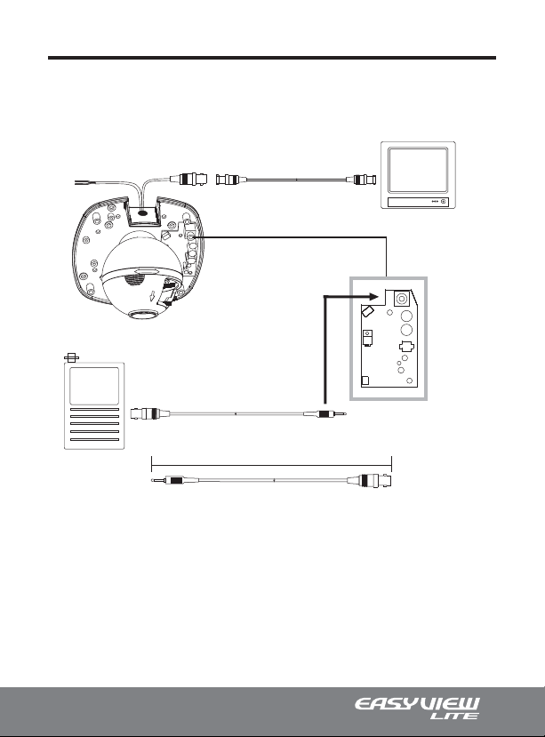
Connecting to Monitors
Follow the diagram below to make proper connections to the CRT Monitor or the Service
Monitor.
12VDC/24VAC
CCTV Monitor
Service Monitor Output
Service Monitor
30cm
CA-SMC30
(Supplied with EasyView™ Lite dome)
Power connection (Auto polarity detection and protection) - 12VDC/24VAC Dual Voltage
•
on Vari-focal Lens models, otherwise 12VDC Voltage for Fixed Lens models.
Service monitor outputs are located on the Camera Power Board, and are only available
•
in the EasyView™ Lite dome cameras equipped with a Vari-focal lens.
11
Page 12
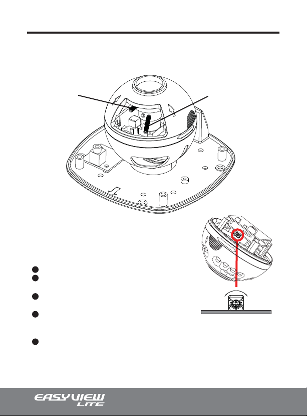
Adjusting the Vari-focal DC Auto Iris Lens
Follow the instruction provided below to make any lens adjustments.
Adjust the Focus
Zoom: Tele A - D Wide
Focus: Far A - D Near
1
Loosen the Zoom & Focus screws.
2
Using the screw, move it LEFT or RIGHT to
the desired position.
3
Once the desired adjustments have been
made, tighten the screw to lock in place.
4
Adjust the Field of View by moving the screw
towards the RIGHT(Wide) to zoom in, or
towards the LEFT (Tele) to zoom out.
5
Adjust the Focus the same way as described
above after the desired zoom position is
established.
Adjust the angle of
Field of View
DARK BRIGHT
For brighter screen turn the
DC Iris level clockwise. For
a darker screen, turn the DC
Iris level counter-clockwise.
12
Page 13

Adjusting the 3-Axis Gimbal
The Gimbal mechanism yields maximum rotation and placement as shown below.
1
Z-Axis: Rotation 355°
2
Y-Axis: Tilting 90°
3
X-Axis: Panning 355°
1
2 2
Tilting 90°
3
Panning 355°Rotation 355°
Tilting 90° w/ IR LED
13
Page 14
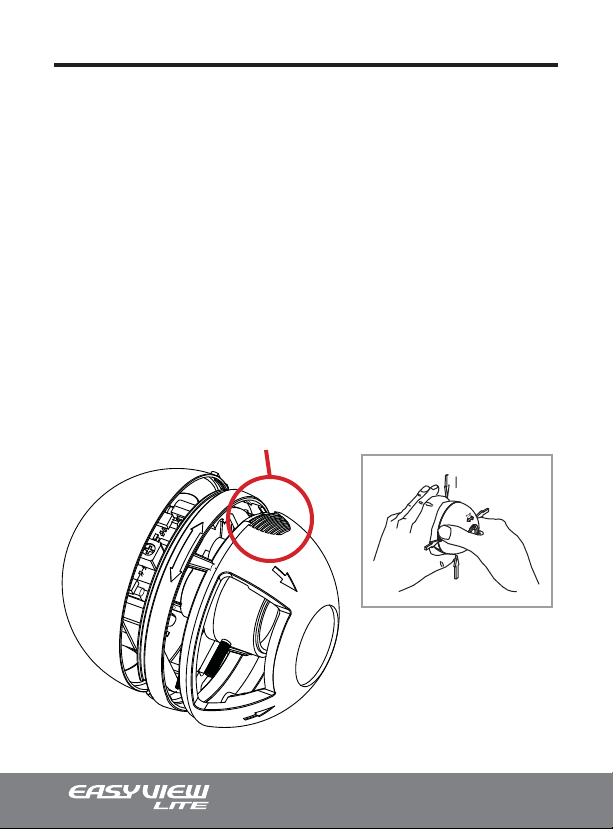
Opening the 3-Axis Gimbal Cover
Dip Switches on the EasyView™ Lite dome cameras are located on the camera
module inside of the Gimbal assembly. To access the Dip Switches, remove the
Gimbal cover temporarily by following the instructions below.
STEP 1
Firmly hold the Gimbal base free of any movement. Press points A & B and pull the
Gimbal cover off from the Gimbal base.
STEP 2
Make the desired Dip Switch adjustments.
STEP 3
Place the Gimbal cover back at the Gimbal base.
Point A
(Point B on the opposite side)
Gimbal Base
Point-B
Point-A
Gimbal Cover
14
Page 15

Switching OFF/ON the IR LEDs
IR LED Dip Switch
This Dip Switch is used to switch OFF/ON the IR LEDs.
Too much IR reflection from a subject causes over-exposure on the most focused area
causing ‘Hot Spots’ within the picture. Adjust this setting can help avoid such problems.
• OFF: Select the OFF setting if the subject in the picture has extreme IR LED reflection.
• ON: Select the ON setting if the subject in the picture has no IR LED reflection.
vu
vmm
15
Page 16

Dip Switch Functions and Operation
Follow the instructions provided below to switch ON/OFF the various available camera
functions and modes.
Function Dip Switch
Each Dip Switch represents
the various functions and
modes. Switch On/Off the
various functions and modes
by following the Dip Switch
position on the right.
16
DIP Switch Functions
ICR Switch Time (2~3 Sec)
ICR Switch Time (4~5 Sec)
FLK On
FLK Off
BLC On
BLC Off
ATW
AWC
On
Off
1
2
3
4
On
Off
On
Off
On
Off
Page 17

Dip Switch Menu Control Terms
A. ICR Filter Delay Timer (ICR Switch Time)
This switch is used to delay the automatic ICR cut-filter.
• ON: The automatic ICR cut-filter is delayed only by 2~3 seconds.
• OFF: The automatic ICR cut-fllter is delayed by 4~5 seconds.
B. FLK Mode
This function is used to correct flickering of the screen when the camera is operating
under certain fluorescent lighting. Flickering most commonly occurs if the fluorescent light
uses a 50Hz power supply.
• OFF: Select the OFF mode if the flickering is observed.
• ON: Select the ON mode for normal operation (Default).
C. BLC (Back Light Compensation)
This function is used to compensate for exposure problem associated with extremely bright
backgrounds causing the subjects to bloom or silhouette.
• OFF: The Backlight Compensation function is turned OFF.
• ON: Select the ON setting for strong backlit environments.
D. WHITE BALANCE (Automatic White Balance)
This function is used to control the white balance under different lighting conditions. Adjust
this setting to calibrate the camera for correct color rendering. The factory default of
‘ATW’ is recommended for optimal performance.
• ATW (Auto Tracking White Balance): Select the ATW mode, the camera will
continuously monitor changes in the ambient color temperatures and automatically set the
White Balance according to the color temperature.
• AWC (Auto White Balance Control): Select the AWC mode and the camera will calibrate
the White Balance to the most optimal setting to the present lighting condition. This setting
will NOT monitor changes in the ambient color temperatures automatically.
17
Page 18
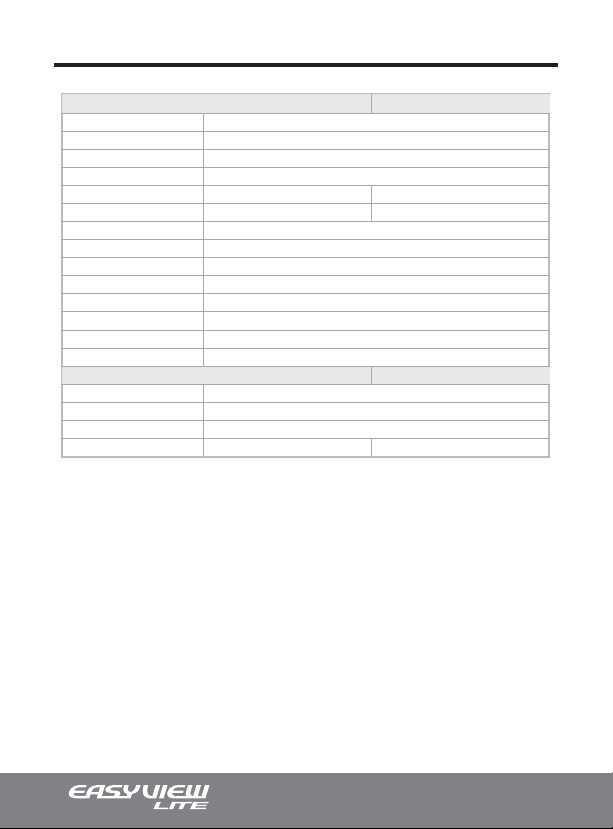
Technical Specifications | NTSC
Technical Specifications
Video Format
Image Sensor
Horizontal Resolution
Day/Night Functionality
Lens Type
Angle of View
Sync System
Effective Pixels
Scanning System
Electronic Shutter
Main Video Output
Service Monitor Output
Minimum Illumination
S/N Ratio
General Information
Operating Temperature
Operating Humidity
Power Consumption
Input Voltage
CD-H2N
NTSC/PAL
1/3” CCD
550 TV Lines
No
Fixed 2.9mm
120°
Internal
768(H) x 494(V)
525 Lines. 2:1 Interlaced
1/60 ~ 1/100,000 sec.
1.0 Vp-p Composite, 75 ohm
1.0 Vp-p Composite, 75 ohm
0.1 Lux
More than 48dB (AGC Off)
CD-H2N
23ºF ~ 113ºF
Within 90% RH
500 mA
12VDC
CD-H39N
Vari-focal 3.8mm-9.5mm
95.5°(W) ~ 37.3°(T)
CD-H39N
12VDC/24VAC Dual Voltage
*specifications are subject to change without any prior notice.
IMPORTANT: All CV Series EasyView™ Lite Vandalproof Dome Cameras have the
same technical specifications as the CD Series indoor dome cameras but has a special
impact resistant dome (IP66) with aluminum housing.
18
Page 19
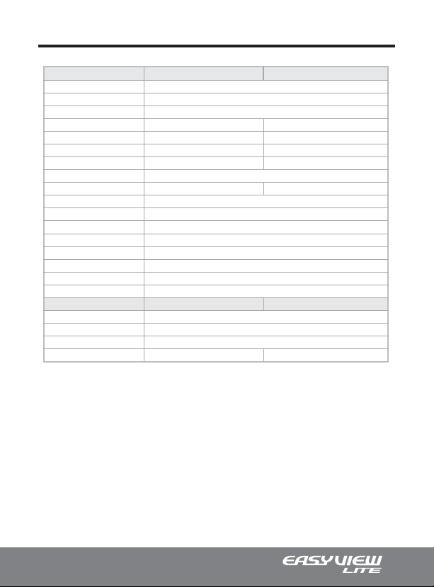
Technical Specifications | NTSC
Technical Specifications
Video Format
Image Sensor
Horizontal Resolution
Day/Night Functionality
Lens Type
Angle of View
IR LED
IR LED Distance
LED Illumination Angle
Sync System
Effective Pixels
Scanning System
Electronic Shutter
Main Video Output
Service Monitor Output
Minimum Illumination
S/N Ratio
General Information
Operating Temperature
Operating Humidity
Power Consumption
Input Voltage
CD-HD2N-L
NTSC/PAL
1/3” CCD
550 TV Lines
Yes
Fixed 2.9mm
120°
18
Up to 50ft.
100°
Internal
768(H) x 494(V)
525 Lines. 2:1 Interlaced
1/60 ~ 1/100,000 sec.
1.0 Vp-p Composite, 75 ohm
1.0 Vp-p Composite, 75 ohm
0.1 Lux (Color), 0.00 Lux (B/W, IR LEDs On)
More than 48dB (AGC Off)
CD-HD2N-L
23ºF ~ 113ºF
Within 90% RH
1 Amp (LED On), 500 mA (Camera Only)
12VDC
CD-HD39N-L
Yes w/ ICR
Vari-focal 3.8mm-9.5mm
95.5°(W) ~ 37.3°(T)
16
60°
CD-HD39N-L
12VDC/24VAC Dual Voltage
*specifications are subject to change without any prior notice.
IMPORTANT: All CV Series EasyView™ Lite Vandalproof Dome Cameras have the
same technical specifications as the CD Series indoor dome cameras but has a special
impact resistant dome (IP66) with aluminum housing.
19
Page 20
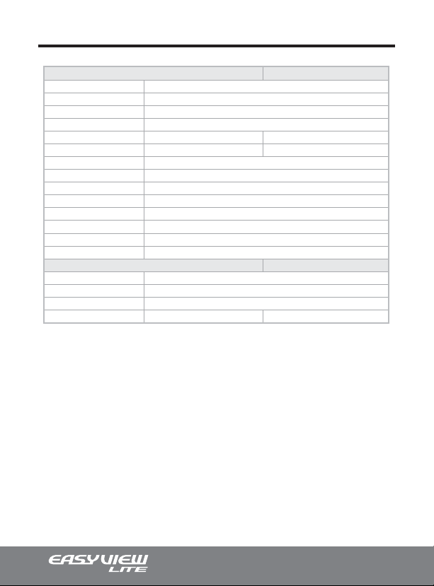
Technical Specifications | PAL
Technical Specifications
Video Format
Image Sensor
Horizontal Resolution
Day/Night Functionality
Lens Type
Angle of View
Sync System
Effective Pixels
Scanning System
Electronic Shutter
Main Video Output
Service Monitor Output
Minimum Illumination
S/N Ratio
General Information
Operating Temperature
Operating Humidity
Power Consumption
Input Voltage
CD-H2P
NTSC/PAL
1/3” CCD
550 TV Lines
No
Fixed 2.9mm
120°
Internal
752(H) x 582(V)
625 Lines. 2:1 Interlaced
1/50 ~ 1/100,000 sec.
1.0 Vp-p Composite, 75 ohm
1.0 Vp-p Composite, 75 ohm
0.1 Lux
More than 48dB (AGC Off)
CD-H2P
-5ºC ~ +45ºC
Within 90% RH
500 mA
12VDC
CD-H39P
Vari-focal 3.8mm-9.5mm
95.5°(W) ~ 37.3°(T)
CD-H39P
12VDC/24VAC Dual Voltage
*specifications are subject to change without any prior notice.
IMPORTANT: All CV Series EasyView™ Lite Vandalproof Dome Cameras have the
same technical specifications as the CD Series indoor dome cameras but has a special
impact resistant dome (IP66) with aluminum housing.
20
Page 21
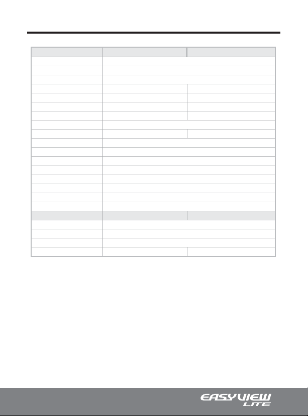
Technical Specifications | PAL
Technical Specifications
Video Format
Image Sensor
Horizontal Resolution
Day/Night Functionality
Lens Type
Angle of View
IR LED
IR LED Distance
LED Illumination Angle
Sync System
Effective Pixels
Scanning System
Electronic Shutter
Main Video Output
Service Monitor Output
Minimum Illumination
S/N Ratio
General Information
Operating Temperature
Operating Humidity
Power Consumption
Input Voltage
CD-HD2P-L
NTSC/PAL
1/3” CCD
550 TV Lines
Yes
Fixed 2.9mm
120°
18
Up to 50ft.
100°
Internal
752(H) x 582(V)
625 Lines. 2:1 Interlaced
1/50 ~ 1/100,000 sec.
1.0 Vp-p Composite, 75 ohm
1.0 Vp-p Composite, 75 ohm
0.1 Lux (Color), 0.00 Lux (B/W, IR LEDs On)
More than 48dB (AGC Off)
CD-HD2P-L
-5ºC ~ +45ºC
Within 90% RH
1 Amp (LED On), 500 mA (Camera Only)
12VDC
CD-HD39P-L
Yes w/ ICR
Vari-focal 3.8mm-9.5mm
95.5°(W) ~ 37.3°(T)
16
60°
CD-HD39P-L
12VDC/24VAC Dual Voltage
*specifications are subject to change without any prior notice.
IMPORTANT: All CV Series EasyView™ Lite Vandalproof Dome Cameras have the
same technical specifications as the CD Series indoor dome cameras but has a special
impact resistant dome (IP66) with aluminum housing.
21
Page 22

Memos & Notes
22
Page 23

Memos & Notes
23
Page 24
 Loading...