

Page 1
PRODUCT
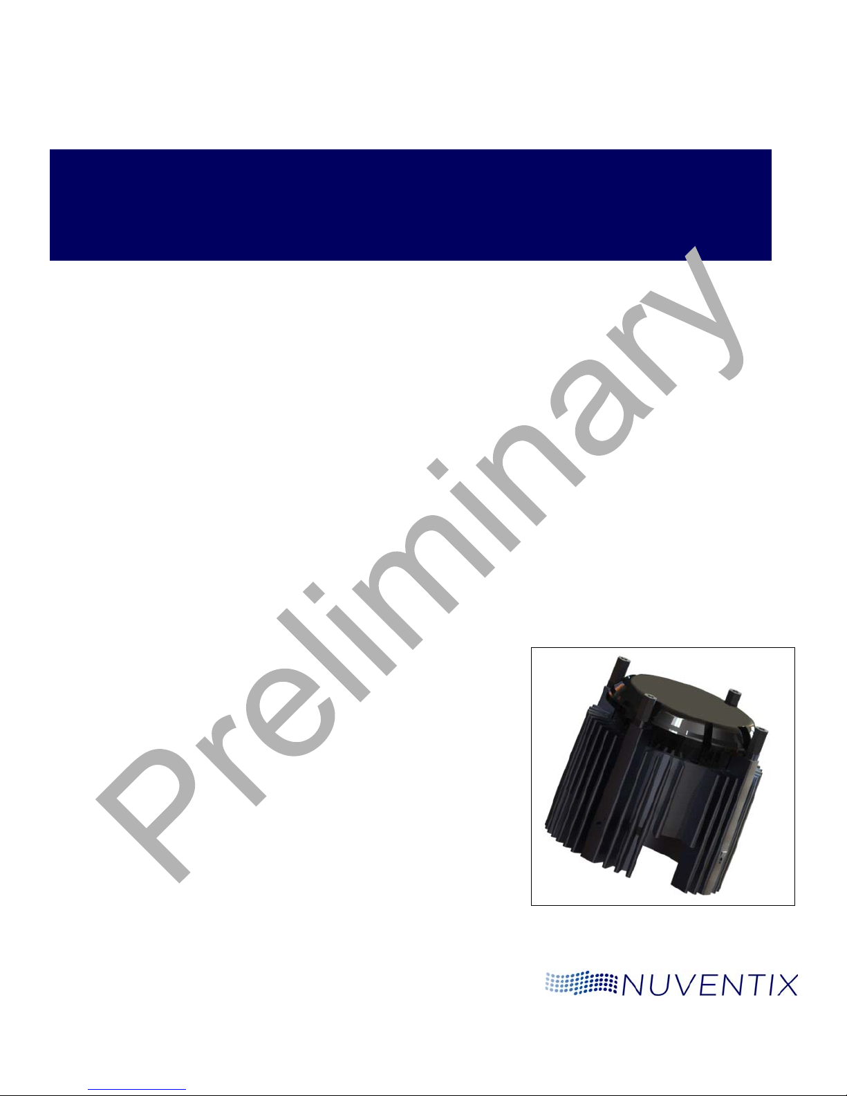
SynJet® Cooler for LED Spot Light
with Heat Sink
Assembly Guide
Version 0.3
February 2010
Page 2
Version History
Document Name: SynJet Spot Light Cooler with Heat Sink Assembly Guide
Document Number: MKTG-DOC-00075
Version and Date Changes
Version 0.1, November 2009 Preliminary Review Draft (rev 11/06)
Version 0.2, Decemb er 2009 Preliminary Release
Version 0.3, February 2010 Preliminary Release
Safety This section discusses safety precautions that should be taken when assembling the SynJet
Spot Light Cooler with Heat Sink.
Failure to follow these instructions carefully may result in person al injury as well as incorrect
assembly leading to overheating of components.
Electrical The SynJet Spot Light Cooler voltages and currents are low and are typically not a hazard. The
customer-supplied LED driver circuit card and connections may have higher voltages present.
This could be a risk during rework operations. Be sure all electrical power is disconnected.
Hot Surfaces The LED and the heat sink surface nearby could be hot to touch, even though the LED and
SynJet Spot Light Cooler are operating as specified. This could become a risk during a rework
and test operation. Allow the assembly to cool before working on it.
Sharp Corners The heat sink may have pointed corners or sharp edges. Use care when handling and during
assembly.
FCC Part 15 (Class B)
Compliance Notice
Nuventix, the Nuventix logo, and SynJet are trademarks or registered trademarks of Nuventix. All other brand and product names may be
This equipment has been tested and found to comply with the limits for a Class B digital device, pursuant to
Part 15 of the FCC Rules. These limits are designed to provide reasonable protection against harmful
interference in a residential installation. This equipment generates, uses and can radiate radio frequency
energy and, if not installed and used in accordance with the instructions, may cause harmful interference to
radio communications. However, there is no guarantee that interference will not occur in a particular
installation. If this equipment does cause harmful interference to radio or television reception, which can be
determined by turning the equipment off and on, the user is encouraged to try to correct the interference by
one or more of the following measures:
Reorient or relocate the receiving antenna.
Increase the separation between the equipment and receiver.
Connect the equipment into an outlet on a circuit different from that to which the receiver is connected.
Consult the dealer or an experienced radio/TV technician for help.
trademarks of their respective companies.
Nuventix, Inc.
4635 Boston Lane
Austin, TX 78735
www.nuventix.com
Copyright © 2009 Nuventix
All Rights Reserved
Phone: 512-382-8100
Fax: 512-382-8101
Contact Sales: 512-382-8100
Page 3

Table of Contents
Safety . . . . . . . . . . . . . . . . . . . . . . . . . . . . . . . . . . . . . . . . . . . . . . . . . . . . . . . . . . . . . . . . . . . . . . . . . . .2
Electrical . . . . . . . . . . . . . . . . . . . . . . . . . . . . . . . . . . . . . . . . . . . . . . . . . . . . . . . . . . . . . . . . . . . . . .2
Hot Surfaces . . . . . . . . . . . . . . . . . . . . . . . . . . . . . . . . . . . . . . . . . . . . . . . . . . . . . . . . . . . . . . . . . . .2
Sharp Corners . . . . . . . . . . . . . . . . . . . . . . . . . . . . . . . . . . . . . . . . . . . . . . . . . . . . . . . . . . . . . . . . . .2
FCC Part 15 (Class B) Compliance Notice . . . . . . . . . . . . . . . . . . . . . . . . . . . . . . . . . . . . . . . . . . . . . . . . . .2
Chapter 1: Introduction
Audience . . . . . . . . . . . . . . . . . . . . . . . . . . . . . . . . . . . . . . . . . . . . . . . . . . . . . . . . . . . . . . . . . . . . . . . . .5
Related Information . . . . . . . . . . . . . . . . . . . . . . . . . . . . . . . . . . . . . . . . . . . . . . . . . . . . . . . . . . . . . . . . .5
Components . . . . . . . . . . . . . . . . . . . . . . . . . . . . . . . . . . . . . . . . . . . . . . . . . . . . . . . . . . . . . . . . . . . . . .5
Packaging . . . . . . . . . . . . . . . . . . . . . . . . . . . . . . . . . . . . . . . . . . . . . . . . . . . . . . . . . . . . . . . . . . . . . . . .7
Requirements . . . . . . . . . . . . . . . . . . . . . . . . . . . . . . . . . . . . . . . . . . . . . . . . . . . . . . . . . . . . . . . . . . . . .7
Handling . . . . . . . . . . . . . . . . . . . . . . . . . . . . . . . . . . . . . . . . . . . . . . . . . . . . . . . . . . . . . . . . . . . . . . . . .8
Thermal Interface Material . . . . . . . . . . . . . . . . . . . . . . . . . . . . . . . . . . . . . . . . . . . . . . . . . . . . . . . . . . . .8
Chapter 2: Assembly Instructions
Preparation . . . . . . . . . . . . . . . . . . . . . . . . . . . . . . . . . . . . . . . . . . . . . . . . . . . . . . . . . . . . . . . . . . . . . . .9
Mounting Features and Assemblies . . . . . . . . . . . . . . . . . . . . . . . . . . . . . . . . . . . . . . . . . . . . . . . . . . . . . .10
SynJet Spot Light Cooler Attachment to Heat Sink . . . . . . . . . . . . . . . . . . . . . . . . . . . . . . . . . . . . . . . .10
LED Attachment and Wiring . . . . . . . . . . . . . . . . . . . . . . . . . . . . . . . . . . . . . . . . . . . . . . . . . . . . . . . .10
Mounting Surface for LEDs . . . . . . . . . . . . . . . . . . . . . . . . . . . . . . . . . . . . . . . . . . . . . . . . . . . . . . . . .11
External Mounting Attachment Options . . . . . . . . . . . . . . . . . . . . . . . . . . . . . . . . . . . . . . . . . . . . . . . .12
Assembly Overview . . . . . . . . . . . . . . . . . . . . . . . . . . . . . . . . . . . . . . . . . . . . . . . . . . . . . . . . . . . . . . . .15
Heat Sink . . . . . . . . . . . . . . . . . . . . . . . . . . . . . . . . . . . . . . . . . . . . . . . . . . . . . . . . . . . . . . . . . . . . .16
Integration . . . . . . . . . . . . . . . . . . . . . . . . . . . . . . . . . . . . . . . . . . . . . . . . . . . . . . . . . . . . . . . . . . . .16
Operation . . . . . . . . . . . . . . . . . . . . . . . . . . . . . . . . . . . . . . . . . . . . . . . . . . . . . . . . . . . . . . . . . . . .16
Disclaimer/Warranty . . . . . . . . . . . . . . . . . . . . . . . . . . . . . . . . . . . . . . . . . . . . . . . . . . . . . . . . . . . . . . . . .17
Contact Nuventix . . . . . . . . . . . . . . . . . . . . . . . . . . . . . . . . . . . . . . . . . . . . . . . . . . . . . . . . . . . . . . . . . . . .17
February 2010 Page 3
Page 4

Table of Contents SynJet Spot Light Cooler with Heat Sink Assembly Guide
Page 4
February 2010
Page 5

Chapter 1
Introduction
This document provides information necessary to develop a production process
for integrating the SynJet Spot Light Cooler with Heat Sink as elements of an
overall lighting assembly.
The SynJet Spot Light Cooler (SLC) is available in several cooling perfor m anc e
levels, as described in the SynJet Spot Light Cooler with Heat Sink Product
Specification. This assembly document is applicable to all five product models.
Audience The audience for this assembly guide is the luminaire assembly and
manufacturing process development team. Marketing and Engineering team
members may find background information in this document useful.
Related Information For additional information, refer to the following:
SynJet Spot Light Cooler with Heat Sink Product Specification
SynJet Spot Light Cooler with Heat Sink Design Guide
Nuventix Technology Overvie w
SynJet Spot Light Cooler with Heat Sink 2D Drawings
SynJet Spot Light Cooler with Heat Sink 3D CAD Model, STEP file format
SynJet Variable Control Application Note
The Nuventix web site at www.nuventix.com for:
Latest Document Updates
New Application Notes
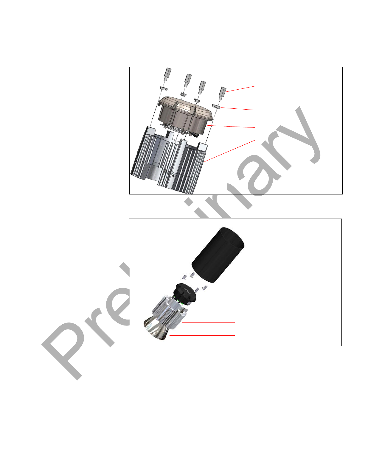
Components The following figures illustrate the components of the SLC. The exploded
Nuventix February 2010 Page 5
assembly shows the SynJet Cooler and the SynJet heat sink. It also shows
optional user supplied items such as the reflector and a cosmetic cover cylinder.
Page 6
Chapter 1: Introduction SynJet Spot Light Cooler with Heat Sink Assembly Guide
Heat Sink
SynJet
®
Standoffs for Securing SynJet
to Heat Sink and for External
Mounting
Locking clip for securing
SynJet to heat sink
SynJet Heat Sink
User Supplied Reflector
Optional User Supplied Cover
SynJet Spot Light Cooler
Figure 1: SynJet Spot Light Cooler and Heat Sink
Page 6 Nuventix
Figure 2: SynJet Spot Light Cooler and Heat Sink With User Supplied Cover and
Reflector
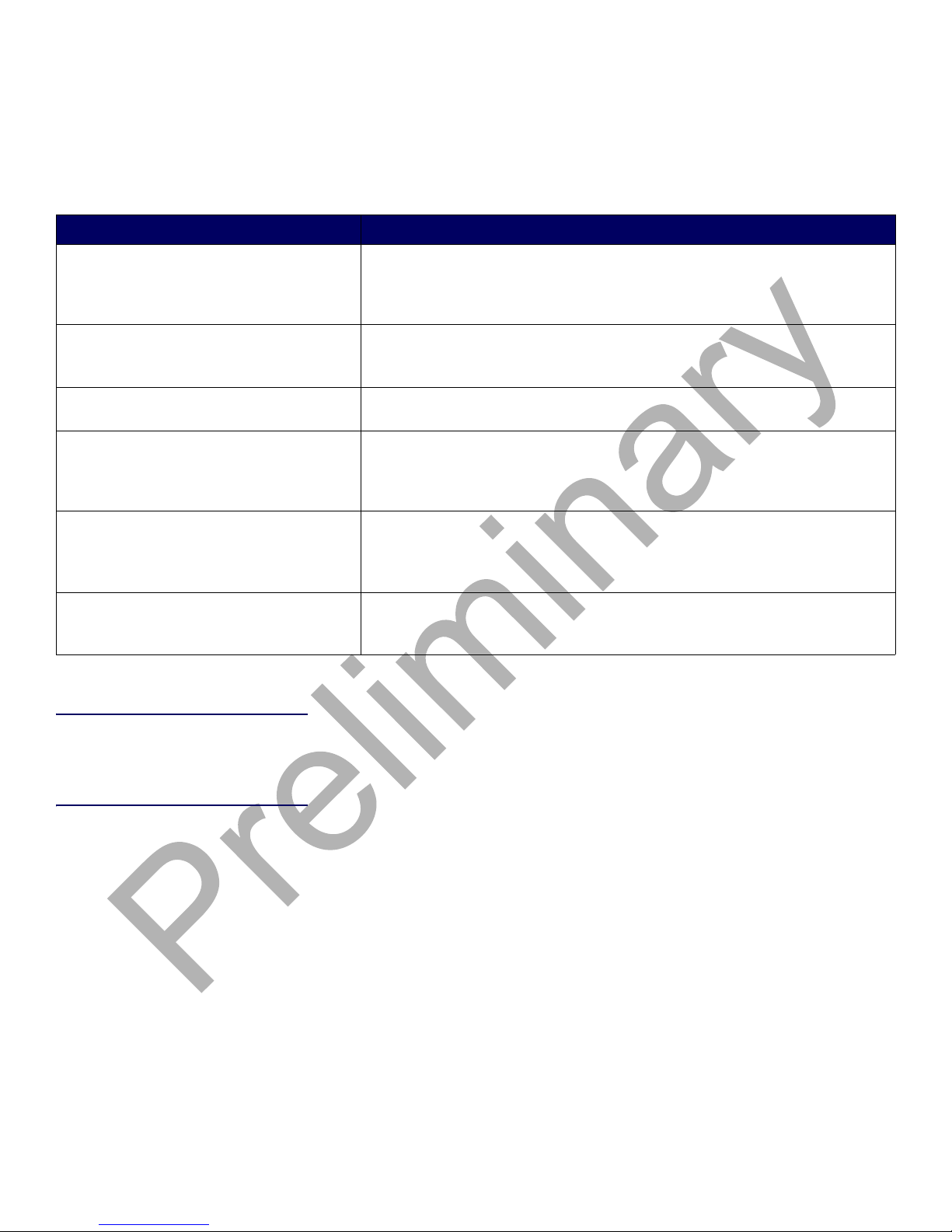
The following table describes each component.
February 2010
Page 7
SynJet Spot Light Cooler with Heat Sink Assembly Guide Chapter 1: Introduction
Table 1:
Component Description
Component Description
SynJet Spot Light Cooler The SynJet Spot Light Cooler is the air mover of the cooling system. The
SynJet module works by creating turbulent, pulsated air-jets that are dir ected
precisely into the heat sink fin channels where thermal management is
needed.
Heat Sink and User Supplied Attachments LED Array and Reflector
The heat sink spreads the heat dissipated from the LED Array over a large
surface area. The LED Array attaches to the flat heat sink surface and the
reflector will attach to the LED or the Heat Sink.
SynJet Spot Light Cooler Driver Board The driver board contains the compone nts needed to operate the SynJet
Spot Light Cooler.
SynJet Cooler to Heat Sink Attachment
Points
The four attachment standoffs mate with tapped holes in the heat sink. The
standoffs screw into the 4 M3 mounting holes on the heat sink and secure the
locking clips to the heat sink and SynJet. For screw size information and
details, see the SynJet Spot Light Cooler 2D Drawings.
SynJet Cooler - Attachment Points for User
Supplied Optional Cosmetic Cover and/or
External Mounting Bracket
The designer can use the standoff screws and/or the tapped ho les in the heat
sink for attachment of a cover or mounting hardware. The Twist-Lock Bumps
on the heat sink can also be used for attachment. See the SynJet Spot Light
Cooler 2D Drawings for details.
User Supplied Optional Cover Cylinder
and/or Reflector
The user may add an optional cover for product style and attachment
requirements. This cover may attach to the heat sink. It may be part of the
fixture external attachment assembly.
Packaging The SynJet Spot Light Coolers and heat sinks are shipped boxed in quantities
based on ease of handling, shipping costs, and customer requirements. Contact
Nuventix Sales for details.
Requirements For assembly, the following customer-supplied items are required:
Four standoff screws are required for attachmen t of the heat sink to the cooler.
Refer to the 2D Drawings for screw size information.
All screws for user designed attachment of LEDs, reflector, luminaire cover,
and external mounting.
Loctite purple (222MS). This should be applied to all screws to ensure a tight fit
for the entire lighting product life.
Thermal Interface Material - for best heat transfer from the LED Array to the
heat sink surface, a TIM should be used to insure good thermal contact.
Nuventix
February 2010 Page 7
Page 8

Chapter 1: Introduction SynJet Spot Light Cooler with Heat Sink Assembly Guide
Handling The thermal, mechanical, and electrical integrity of the luminaire can be
significantly influenced in the assembly process.
The LED drive circuit, the SynJet driver circuit, plus other power and control
circuits in the luminaire, have typical industry levels of built-in ESD tolerance.
However, unusual environmental conditions and handling can create exceptional
levels of ESD that could cause damage.
IMPORTANT! Electrostatic Discharge (ESD) is a significant cause of electronic
circuit failure. A failure may:
be immediate
occur later due to a weakened component
appear as an early service life failure.
An industry-standard assembly and test area mu st ha ve prope r
ESD protected work stations. In addition, the staff must have ESD
prevention education.
The SynJet Spot Light Cooler electronics require
industry-standard care and use of proper ESD protection during
assembly and test.
When handling the SynJet Spot Light Cooler, use care with the wiring and the
circuit card. The SynJet Spot Light Cooler is designed for normal assembly
operations. With excessive force, the wires and components can b e over-stressed
and broken.
The SynJet Spot Light Cooler plastic housing has been designed to withstand
normal assembly forces. Clamping or force fits can create very strong local forces
that could damage or weaken the cooler housin g, thus creating an earl y life failure
risk.
The SynJet Spot Light Cooler contains magnets. Small particles of iron, screws,
and other magnetic materials from secondary machining or that are loose in the
assembly area may be attracted to the housing or the PCBA. They could interfere
with performance or cause a failure. Be sure any particles are removed afte r
machining and the assembly work area is clean.
If secondary machining operations are performed on the heat sink, remove the
SynJet Spot Light Cooler to avoid damage to the housing or circuit card.
Thermal Interface Material Thermal interface material (TIM) is important between surfaces th at transfer hea t.
Refer to the SynJet Spot Light Cooler with Heat Sink Design Guide for additional
information on selection and use of TIM.
For the best heat transfer, properly clean and prepare the transfer mating
surfaces. Refer to the TIM supplier's recommendations for surface preparation.
Page 8 Nuventix
Nuventix does not specify or supply a specific TIM. This is the responsibility of the
luminaire design team's thermal engineer. Nuventix Sales can provide support
and consultation.
February 2010
Page 9

Chapter 2
Assembly Instructions
This chapter shows you how to assemble the SynJet Spot Light Cooler with Heat
Sink. It includes suggestions for the assembly with customer specified LEDs,
reflector, and cover. This chapter includes:
Preparation Steps - describes steps required prior to assembly
Mounting Features and Assembly - includes figures that show various SynJet
Spot Light Cooler and heat sink mounting features, partial assemblies, and an
assembled SynJet Spot Light Cooler with heat sink
Assembly Overview with more detailed process sequence steps.
Preparation The face of the heat sink is machined for improved flatness. Depending upon the
luminaire design, secondary machining operations by the customer may be
necessary for attachment of the LEDs to the face of the heat sink. Since the face
of the heat sink is not coated, it can be machined more easily. If additional tapped
holes are added to the heat sink, these machining operations should also be done
prior to assembly . For specific customer needs, custom mou nting features may be
special ordered.
Heat transfer is significantly improved by cleaning the heat sink surface after
machining operations and prior to attachment of the LEDs.
IMPORTANT!The surface must:
be clean
have high spots and roughness removed
conform to surface drawing specification
The SynJet Spot Light Cooler is shipped with the ends of the control and power
wires stripped and tinned. If a connector is used to connect the p ower supply, the
wires are ready for the customer to crimp or solder them to the connector.
See the following table for further information.
Table 2:
Power and
Control
Nuventix February 2010 Page 9
Power and Control Wiring Specifica t io n
VDC Gnd Control Overall Length AWG (Stranded) Wire Diameter
Red Black Blue 600 mm 26 1.02 (±0.04) mm
Red Black Blue 240 mm 26 1.02 (±0.04) mm
Page 10
Chapter 2: Assembly Instructions SynJet Spot Light Cooler with Heat Sink Assembly Guide
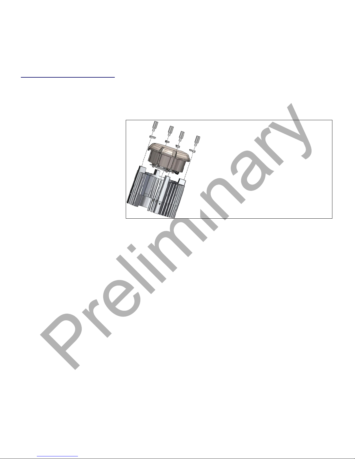
SynJet Cooler mates with the wide fins of the heat sink.
SynJet slides straight down onto the heat sink and the
holes align with the tapped holes in the wide fins
Mounting Features and
Assemblies
SynJet Spot Light Cooler Attachment
to Heat Sink
This section provides assembly graphics and is followed by an assembly outline.
This outline gives the recommended process steps for integration.
Detailed descriptions of each of the assembly elements and their mounting and
wiring features are provided.
This section discusses attachment of the heat sink to the SynJet Spot Light
Cooler.
Figure 3:
SynJet Spot Light Cooler Tabs
The lower rim of the cooler has four tabs with holes that can be aligned with the
tapped holes in the four flat areas on the wide fins on the heat sink. The alignme nt
should also be checked for proper wire exit routing. The four screws used for
attachment should have Loctite 222 MS applied to the threads to assure a tight fit
for the life of the luminaire. They should be tightened to a torque value of 0.45
N-m (4 inch-lbs) ± 10%. Refer to the SynJet Spot Light Cooler 2D Drawings for
dimensions, sub-assembly views, tapped hole positions, and screw sizes.
To attach the heat sink and cooler, complete the following steps.
1. Align the cooler's power wire bundle with the notched wide heat sink fin. Be
sure they are routed correctly from the PCBA.
2. Push the cooler gently onto the heat sink, shifting it slightly so it also aligns the
four screw holes in the cooler and the heat sink. Check the notch again for
correct wire routing.
3. Apply Loctite 222MS to the screw threads.
4. Align the standoff screws and locking clips with the holes and tighten the four
screws.
LED Attachment and Wiring This section provides information on connecting the SLC with heat sin k to an L ED
or LED array.
Page 10 Nuventix
February 2010
Page 11

SynJet Spot Light Cooler with Heat Sink Assembly Guide Chapter 2: Assembly Instructions
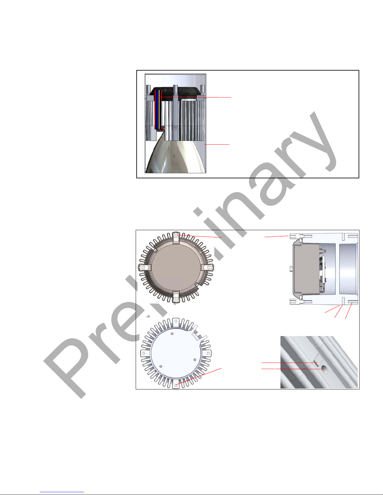
LED Attachment Surface
LED Power Wires Exit
Route
Optional Tapped Holes
(3) for Attachment of
LEDs and/or Reflector
Optional Four Tapped Holes
for Fixture Attachment
Figure 4: LED Mounting
Mounting Surface for LEDs To mount an LED array or MCPCB to the SynJet Spot Light Cooler, the inner
center of the heat sink has a flat surface area as shown in the figure above. The
LED array is attached to this surface. This surface is machined and provides a flat
surface to make good thermal contact with the LED array, MCPCB, or other
mounting board. Standard mounting options for various LED hole patterns are
available. Nuventix can add custom hole patterns. Requests for custom holes
should be reviewed with Nuventix Sales. TIM is usually added to provide better
heat transfer.
The customer may perform a secondary machining operation to add features to
the mounting surface (such as addit i onal threaded holes) dependent upon
application needs. The customer may alternatively choose to use a thermal epoxy
method to attach the LEDs and provide a good thermal path.
Wire Routing The Figure 5 shows the wires emerging from the SynJet Cooler and LED array
and their routing along the heat sink fin channel to exit the assembly for
connection to the power source. The figure shows a cylinder surrounding the
SynJet Cooler, heat sink, and reflector. The wires may exit through the side or the
end of the cylinder.
Nuventix
February 2010 Page 11
Page 12
Chapter 2: Assembly Instructions SynJet Spot Light Cooler with Heat Sink Assembly Guide
Cylinder surrounding SynJet cooler
SynJet Cooling Control and Power
Wires plus LED Power Wires
A
D
C
B
A - Top Moun t Standoffs
B - Optional Twist Lock Features
C - Optional Side Mount Tapped Holes
D - Optional End Mount Tapped Holes
A
B
C
D
Figure 5: SynJet Cooler and LED Array Wire Routing
External Mounting Attachment
Options
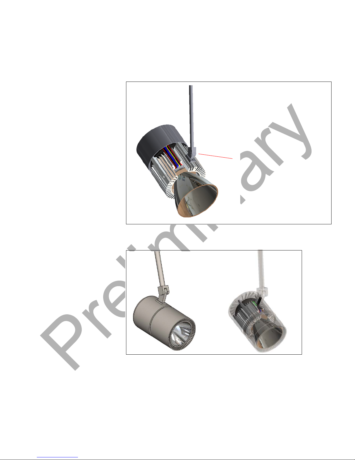
Figure 6 shows the three perimeter rows of optional external attachment holes;
one row in the SynJet cooler attachment end of the heat sink, one at the light exit
end of the heat sink, and one at the mid-point of the heat sink.
Page 12 Nuventix
Figure 6:
External Attachments Points
February 2010
Page 13
SynJet Spot Light Cooler with Heat Sink Assembly Guide Chapter 2: Assembly Instructions
External Mounting Attachment
Example: Heat Sink to Arm
Example 1 Figure 7 and Figure 8 show concept design examples using one of the center
perimeter heat sink holes to attach the light fixture to the support arm.
Example 2
Figure 7:
Attachment to Support Arm
Figure 8: Attachment to Support Arm
Nuventix
February 2010 Page 13
Page 14
Chapter 2: Assembly Instructions SynJet Spot Light Cooler with Heat Sink Assembly Guide
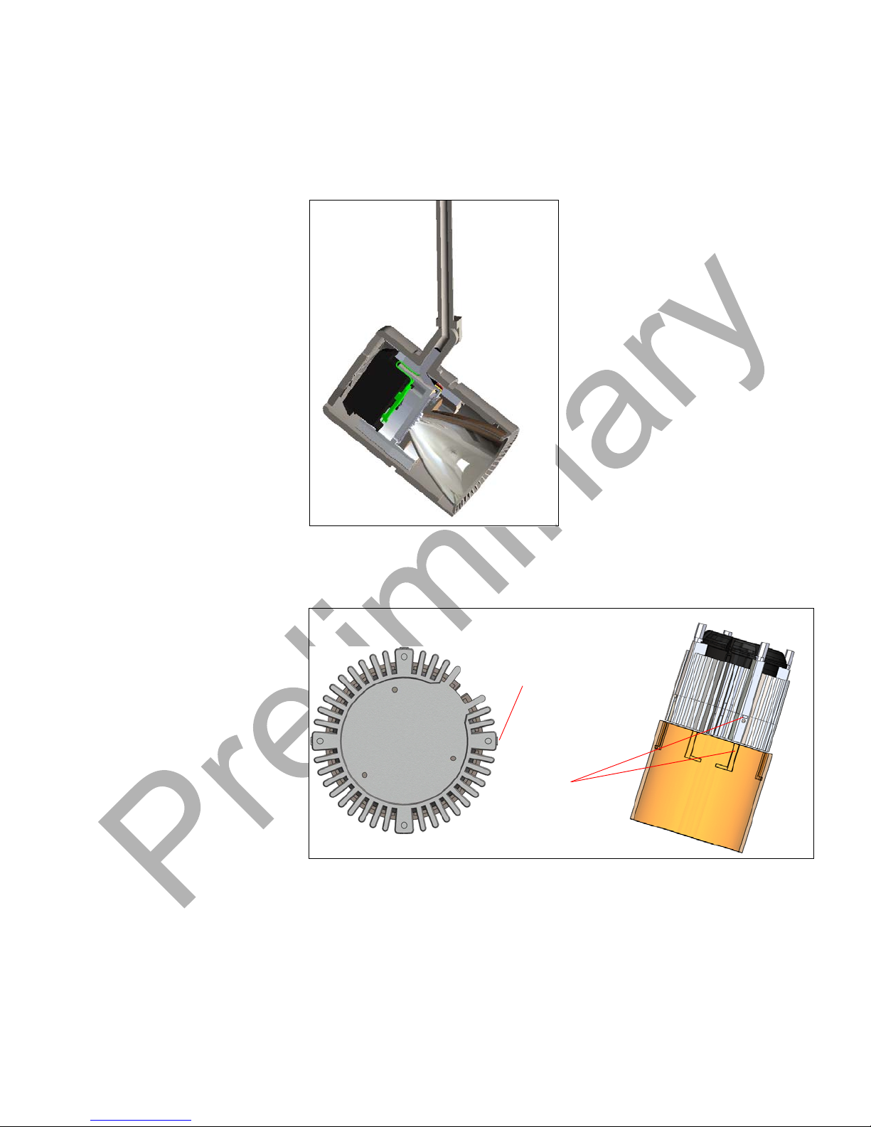
Protrusions for twist
lock style attachment
Protrusions align with
grooves in cover for a
screw-less assembly
Example 3 Figure 9 shows a concept design example using one of the cen te r per imeter he at
sink holes to attach the light fixture to the support arm.
Example 4
Figure 9:
Attachment to the Center Perimeter Heat Sink Hole
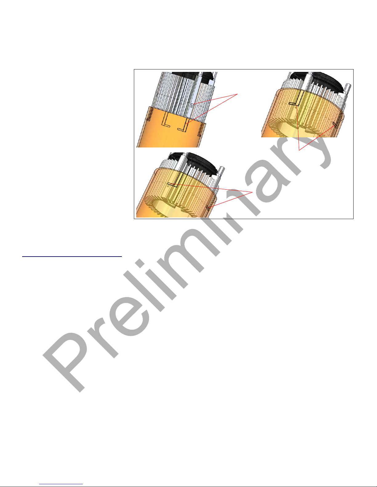
The following figures provide information on quick twist loc k cover attachment.
Figure 10:
Twist Lock Feature
Page 14 Nuventix
February 2010
Page 15
SynJet Spot Light Cooler with Heat Sink Assembly Guide Chapter 2: Assembly Instructions
Align protrusions with
grooves in cover
Slide cover into position
Twist cover to lock
into final position
Figure 11: Twist Lock Assembly
Assembly Overview The SynJet Spot Light Cooler is at the heart of the final assembly.
This section outlines a suggested assembly process. It may be used as a guide
and checklist to be fine-tuned to the specific luminaire product.
The components for the process include the SynJet Spot Light Cooler, heat sink,
LEDs, optics or diffuser, power connections, and LED driver electronics, plus
customer sub-assembly parts. The final step is integration with the luminaire.
This paragraph and the next figure give an overview and general comments on
important considerations for the assembly process.
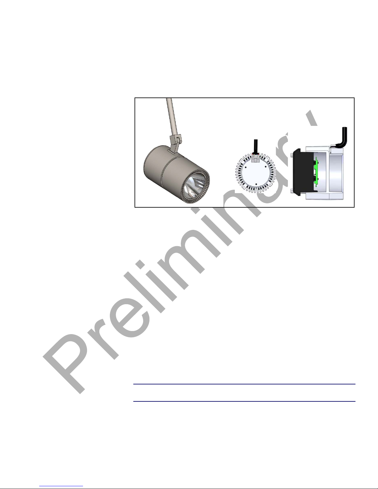
1. The figure below shows a completed assembly sample on the left. The
cross-section on the right has the external cylinder and reflector rem oved for a
clear understanding of the assembly. This is an example, one style of many, a
luminaire designer may create.
2. Each design will have several basic points for consideration in the assembly
flow process.
a. In this example, the complete light engine - SLC with heat sink plus LEDs -
is first assembled.
b. The Rear Half Cylinder is then attached to th is sub-assembly using the
attachment points on the heat sink.
c. The SynJet power wires and the LED power wires are planned to route
directly to the tunnel in the arm. They should not wrap around the Cooler or
heat sink more than necessary.
Nuventix
February 2010 Page 15
Page 16
Chapter 2: Assembly Instructions SynJet Spot Light Cooler with Heat Sink Assembly Guide
d. In this design the rear half of the cy linder att aches to the heat sink and thus
holds the weight of the assembly and the front half of the cylinder attaches
to the rear half with a quick twist lock.
Heat Sink
Figure 12:
To assemble the heat sink, LED, and optics complete the following steps:
Assembly and Wire Routin g
1. Complete secondary machining operations on the heat sink.
2. Apply TIM.
3. Attach the LED Array MCPCB with reflector to the heat sink face.
4. Route LED power wires through the heat sink holes.
5. Add any clips or other fastening features to the heat sink attachment points for
later optional addition of a cover or external mounting bracket.
Integration To integrate the luminaire with the SynJet Spot Light Cooler, complete the
following steps:
1. Align and mount the SynJet Spot Light Cooler to the luminaire using the holes
in the heat sink or a customer designed bracket.
2. Connect power to the SynJet Spot Light Cooler and the LEDs.
3. Turn the power on and then off to test the assembly.
Operation When power is turned on, the SynJet Spot Light Cooler begins operating
immediately.
NOTE: Due to its extremely quiet air flow, you must be in close proximity to feel
the air flow and hear the cooler operating.
Page 16 Nuventix
February 2010
Page 17

Disclaimer/Warranty
Customers are responsible for testing products for their unique applications. Any
information furnished by Nuventix and its agents is believed to be accurate and
reliable. However, since every potential application cannot be anticipated,
Nuventix makes no warranties as to the fitness, merchantability, or suitability of
any Nuventix products for any specific or general uses. Nuventix shall not be
liable for incidental or consequential damages of any kind.
Contact Nuventix
Nuventix Inc.
4635 Boston Lane
Austin, TX 78735
512-382-8100 (phone)
512-382-8101 (fax)
www.nuventix.com
For company and product information:
[email protected]
For sales information:
[email protected]
 Loading...