


User Manual
Quincy 390 / Col tri MCH 36
Electric
Nitrox System
REV: 03.19
www.nuvair.com

Q-390/MCH 36Electric Nitrox System
If you have any questions on this equipment please contact technical support at:
Nuvair
1600 Beacon Place
Oxnard, CA 93033
Phone: +1 805 815 4044
Fax: +1 805 486 0900
Email: info@nuvair.com
Hours: Monday through Friday
8:00 AM to 5:00 PM PST USA
If you lose this manual, you can download the latest version at www.nuvair.com.
This user manual contains important safety information and should always be available to
those personnel operating this equipment. Read, understand and reta in all instructions
before operating this equipment to prevent injury or equipment damage.
Every effort was made to ensure the accuracy of the information contained within. Nuvair, however,
retains the right to modify its contents without notice. If you have problems or questions after reading
the manual, stop and call Nuvair at +1 805 815 4044 for information.
NUVAIR
Q-390/MCH36 Nitrox system User Manual
Page
2

Q-390/MCH 36Electric Nitrox System
Table of Contents
Introduction
1.0 Introduction ..................................................................................................................................... 4
2.0 Safety Warnings and Warning Graphics Defined............................................................................. 5
3.0 Safety and Operation Precautions ................................................................................................... 7
4.0 Legal Precautions ............................................................................................................................ 8
5.0 Theory of Operation .......................... ....... ...... ................................................................................. 9
6.0 Low Pressure Air Compressor Technical Data …………………………………………………………. 10
7.0 High Pressure Compressor Technical Data ………………………………………..…………..…........ 11
8.0 System Components ………………………………………...........……………………………………..... 12
9.0 Nitrox System Specifications ............................................................................................................ 13
10.0 Nitrox System Component Identification……………...…………........................................................ 14
11.0 System Drawing/Schematic …………………………………………….…………………………………. 17
12.0 System Flow Chart ……………………………………………………………………………………….… 18
Setup, Operation, and Maintenance
13.0 Installing the Nitrox System ……………........................................................................................... 19
13.1 Precautions ......................................................................................................................... 19
13.2 Attaching Nitrogen Discharge Hose (Optional) ................................................................... 19
13.3 Electrical Power Connection .............................................................................................. 20
13.4 Check Compressor Lubricant Levels …………………………………………………………… 21
13.5 Control Panel Identification……………………………………………………………………….21
14.0 Pre-Operation Instructions ............................................................................................................... 22
14.1 Oxygen Analyzer Calibration............................................................................................... 22
15.0 Producing nitrox ............................................................................................................................... 24
15.1 Flow to Membrane and Setting Proper Pressure................................................................ 24
15.2 Final Adjustments Before Pumping Nitrox ......................................................................... 24
15.3 Pumping Nitrox ................................................................................................................... 26
15.4 Pumping Air ......................................................................................................................... 28
15.5 Shutting Down ..................................................................................................................... 28
16.0 Nitrox Operational Notes .................................................................................................................. 29
16.1 Correlation of Feed Air Pressure to Oxygen Content .......................................................... 29
16.2 Hot Fills ............................................................................................................................... 29
17.0 Maintenance ...................... ......... ....... ...... ....... .................................................................................. 30
17.1 Daily Maintenance ............................................................................................................... 30
17.2 Routine Maintenance .......................................................................................................... 31
17.3 Compressor lubricant .......................................................................................................... 32
17.4 LP Feed Air Filtration and Bowls........................................................................................ 34
17.5 LP Filtration Inspection …………………………………………………………………………. 34
17.6 Changing LP Filtration Elements ……………………………………………………………… 35
17.7 HP Compressor Filtration .............……………………………............................................. 36
18.0 Spare Parts List …………................................................................................................................. 37
19.0 Service Record Log ......................................................................................................................... 38
20.0 Appendix .......................................................................................................................................... 39
20.1 Supply and Breathing Air Specific ati ons .............................................................................. 39
20.2 Filter Element Life Factors .................................................................................................. 39
Material Safety Data Sheets ............................................................................................................ 40
Owner’s Warranty Responsibilities ……… ……… ………………....................................................... 43
Warranty ………………………………………………… ………… ……………………………………….. 42
Additional Record of Changes ……………………………………………………………………………. 43
Separate Manuals Included:
Nuvair Pro O
Coltri MCH-36 High Pressure Compressor Manual
TM
Oxygen Analyzer Operation Manual
2
NUVAIR
Q-390/MCH36 Nitrox system User Manual
Page
3
Q-390/MCH 36Electric Nitrox System
1.0 Introduction
Nuvair has taken extreme care in providing you with the information you will need to operate this
system. However, it is up to you to carefully read this manual and make the appropriate decisions
about system safety.
This manual will assist you in the proper set-up, operation and maintenance of the Nuvair nitrox
system. Be sure to read the entire manual.
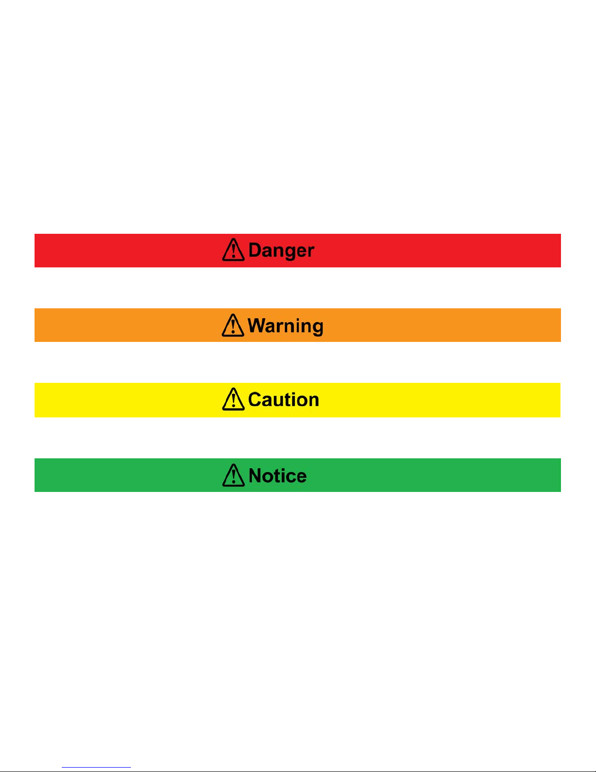
Throughout this manual we will use certain words and symbols to call your attention to conditions,
practices, and / or techniques that may directly affect your safety. Pay particular attention to
information introduced by the following signal words:
Indicates an imminently hazardous situation, which if not avoided, will result in serious
personal injury or death.
Indicates a potentially hazardous situation, which if not avoided, could result in serious
personal injury or death.
Indicates a potentially hazardous situation, which if not avoided, may result in minor or
moderate injury. It may also be used to alert against unsafe practices.
Notifies people of installation, operation or maintenance information which is important but
not hazard-related.
NUVAIR
Q-390/MCH36 Nitrox system User Manual
Page
4
Q-390/MCH 36Electric Nitrox System
2.0 Safety Warnings
This equipment is used to provide breathing gas for the purpose of underwater life support.
Read this manual in its entirety. Failure to heed the warnings and cautions contained in this
document may result in severe injury or death.
The equipment you will be using to manufacture nitrox (oxygen rich air) will expose you to
both low and high-pressure gas. Gas, even under moderate pressures, can cause extreme
bodily harm. Never allow any gas stream to be directed at any part of your body.
Any pressurized hose can cause extreme harm if it comes loose or separates from its restraint
(or termination) while under pressure and strikes any part of your body. Us e appropriate care
in making and handling all gas connections.
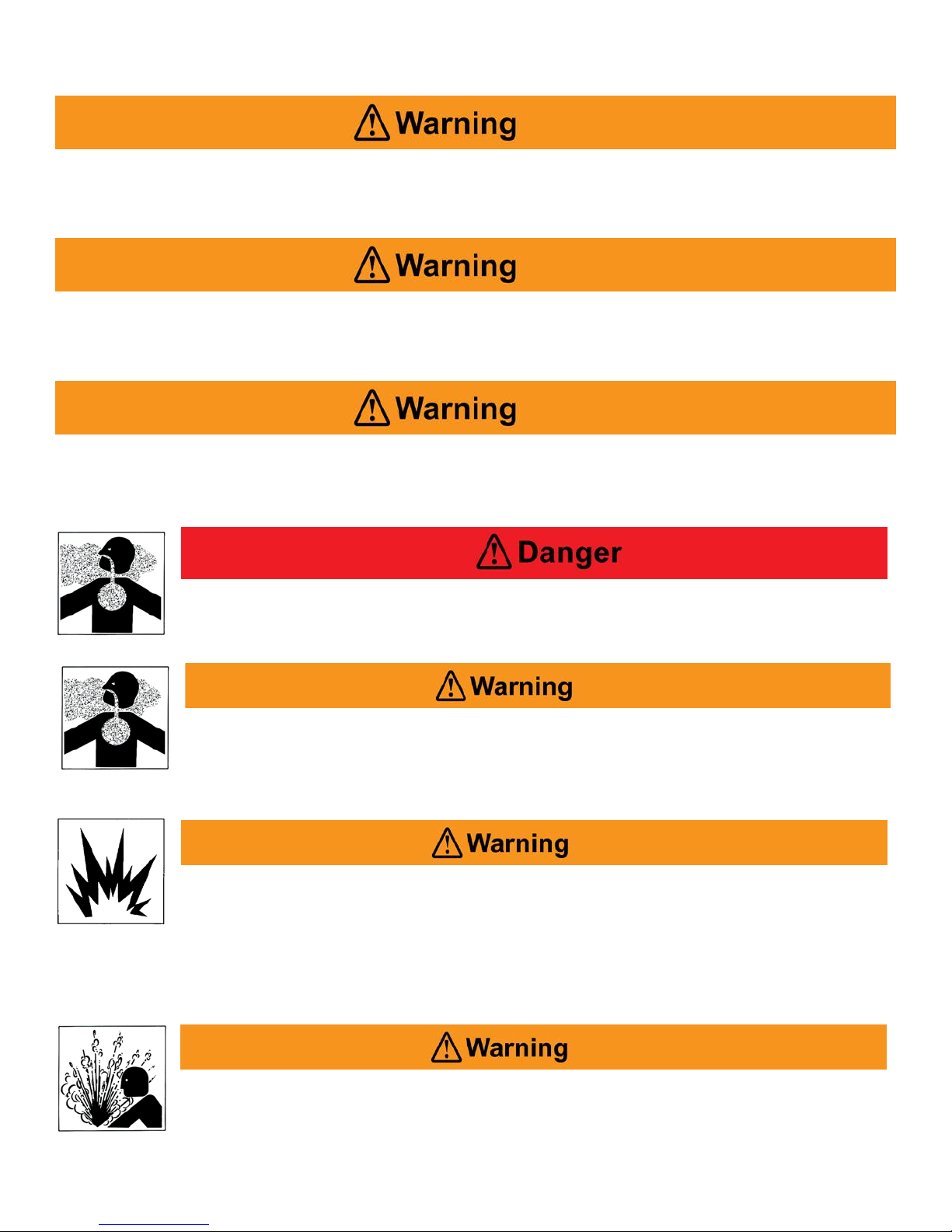
Pure nitrogen is a colorless, odorless, tasteless gas that will not support life.
Breathing gas mixtures containing more than 84% nitrogen at surface pressures
will lead to unconsciousness and may cause death.
The nitrogen discharge from the membrane system must be vented to the
exterior of any closed building, boat, or similar enclosed s pace. Breathing gas
mixtures containing more than 84% nitrogen at surface pressure will lead to
unconsciousness and may cause death.
Do not use any form of mineral oil or synthetic l ubricant not rated for nitrox in
any compressor in this system. Use only the recommended nitrox c ompressor
lubricant. Never mix the nitrox compressor lubricant with other lubricants.
Remove all existing lubricant and replace with the proper nitrox compressor lubricant prior to
installing the membrane system. The use of improper lubricants can lead to fire or explosions,
which may cause serious personal injury or death.
Do not use this system to produce nitrox mixtures containing more than 40%
oxygen. Pumping nitrox mixtures with higher concentrations of oxygen may
lead to fires or explosions, which can cause serious personal injury or death.
NUVAIR
Q-390/MCH36 Nitrox system User Manual
Page
5

Q-390/MCH 36Electric Nitrox System
The use of enriched air nitrox does not eliminate the risk of decompression sickness (DCS) in
diving. Decompression sickness can lead to permanent disability or death.
Do not pump nitrox mixtures at pressures above the HP compressor
manufacturer’s rating, and never above 3600 psi (250 bar). The system is not
rated for pressures above 3600 psi (250 bar). Higher pressures may lead to
explosions which may cause serious personal injury or death.
Ambient room temperature should never exceed 104o F (40o C) during operation of the nitrox
system. Operation at higher temperatures may lead to system damage and malfunction. A
damaged membrane will not produce the correct nitrox mixture which can lead to severe
personal injury if the gas is used for diving purposes without proper analysis.
Warnings Graphics Defined:
Moving belts Electrocution Fire Eye protection Gas inhalation
Skin damage Explosion Explosion Electrocution Machinery
Abbreviations commonly used in this manual:
PSI Pounds Per Square Inch CFM Cubic Feet per Minute
HP High Pressure RPM . Rotations per Minute
LP Low Pressure PPM Parts Per Million
O2 Oxygen L/min Liters Per Minute
CO Carbon Monoxide O2% Oxygen Percentage of Gas
CO2 Carbon Dioxide B.P. Back Pressure
N Nitrogen
NUVAIR
Q-390/MCH36 Nitrox system User Manual
Page
6

3.0 Safety And Operation Precautions
Because a compressor is a piece of machinery with moving and rotating parts, the same precautions
should be observed as with any piece of machinery of this type where carelessness in operations or
maintenance is hazard ous to personnel. In additi on to the many obvious saf ety precautions, those list ed
below must also be observed:
1) Read all instructions completely before operating any compressor or nitrox system.
2) For installation, follow all local electrical and safety codes, as well as the National Electrical Code
(NEC) and the Occupational Safety and Health Administr ation (OSHA) standards.
3) Electric motors must be securely and adequat ely grounded. This ca n be accomplished by wiring with a
grounded, metal-clad raceway system to the compressor starter; by using a separate ground wire
connected to the bare m etal of the motor frame; or other suitable means.
4) Protect all power cables from coming in contact with sharp objects. Do not kink power cables and
never allow the cables to c ome in contact with oil, grease, hot surfaces, or chemi c als.
5) Make certain that power source conforms to the requirements of your equipment.
6) Pull main electrical disconnect switch and disconnect any separate control lines, if used, before
attempting to work or perform maintenance. “Tag Out” and
7) Do not attempt to remove any parts without first relieving the enti r e system of pressure.
8) Do not attempt to service any part while system is in an operational mode.
9) Do not operate the system at pressures in excess of its rating.
10) Do not operate compressor at speeds in excess of its rating.
11) Periodicall y check all safety devices for proper operation. Do not change pressure setting or restrict
operation in any way.
12) Be sure no tools, rags or loose parts are left on the nitrox system.
13) Do not use flammable solvents for cleaning the air inlet filters or elements and other parts.
14) Exercise cleanliness during maintenance and when making repairs. Keep dirt away from parts by
covering parts and exposed openings with clean cloth or K raft paper.
15) Do not operate the compressor without guards, shields, and screens in place.
16) Do not install a shut-off valve in the compressor discharge line, unless a pressure relief valve, of
proper design and size, is ins talled in the line bet ween the compressor unit and shut-off valve.
17) Do not operate this compressor in an y location where there is a possibility of toxic levels of carbon
monoxide (CO), carbon dioxide (CO
the compressor intake.
18) Be careful when touching the exterior of a rec ently run electric, gasoline, or diesel motor - it m ay be
hot enough to be painful or cause inj ury. With modern mot ors this condition is normal if operated at
rated load - modern motors ar e bui lt to operate at higher temperatures.
19) Inspect unit daily to observe and correct any un s afe operating conditions found.
20) Do not “play around” with compressed air, or direct air stream at body, because this can cause
injuries.
21) Compressed air f rom this machine absolutely m ust not be used for food processing or brea thing air
without adequate downstream filters, purifier s and c ontrols and periodic air quality testing.
22) Always use an air pr essure-regulating devic e at the point of use, and do not use air pressure greater
than marked maximum pressure.
23) Check hoses for weak or worn conditions before each use a nd make certain that all connec tions are
secure.
The user of any compressor or nitrox system manufactured by Nuvair is hereby warned that failure to
follow the preceding Safety and Operation Precautions can result in injuries or equipment damage.
However, Nuvair does not st ate as fact or does not mean to imply that the preced ing list of Safety and
Operation Precautions is all -inclusive, and f urther that t he observance of this list will prevent all inj uries or
equipment damage.
NUVAIR
Q-390/MCH36 Nitrox system User Manual
Q-390/MCH 36Electric Nitrox System
“Lock Out” all power sources.
), nitrogen (N), or any flammable or toxic fumes being sucked into
2
Page
7

Q-390/MCH 36Electric Nitrox System
4.0 Legal Precautions
It is highly recommended that a nitrox fill log be maintained when filling scuba cylinders to document
the following information. This log must be of permanent binding style with no loose pages.
• Fill date and time of day
• Tank serial number
• Supplier’s check of oxygen content O2% plus signature and dat e
• User’s check of oxygen content O2% plus signature and date
• Fill pressure
• MOD (maximum operating depth) in user’s handwriting
• Nitrox certifying agency and card number
NUVAIR
Q-390/MCH36 Nitrox system User Manual
Page
8

Q-390/MCH 36Electric Nitrox System
5.0 Theory of Operation
The Nuvair high pressure nitrox system is a turnkey package that produces oxygen-rich air (nitrox)
and then compresses it with a High Pressure (HP) compressor to fill scuba tanks or storage cylinders.
The package is designed to be fully automatic. Although it is described as the “nitrox compressor”, it
can also be used to pump air.
This nitrox system allows for efficient and cost effective nitrox production using electric power, without
the hazards or expense of blending with stored high-pressure oxygen (O2). Instead, the system uses
a semi-permeable membrane to produce nitrox from air. A portion of the nitrogen in air is separated
out, leaving an oxygen rich nitrox mixture.
This system uses a Quincy LP compressor, air aftercooler, and filtration to provide the membrane
system with a source of clean, pressurized feed air for separation. The air is filtered to CGA Grade D
or better air quality prior to entering the membrane system so it will not damage or plug the
membrane fibers. Specifications for Grade D air are provided in the appendix.
The Package’s membrane system is rated for a maximum feed air pressure of 300 psi (21 bar) and
has been configured to work well with the 175 P.S.I (12 bar) maximum pressure delivered by the LP
compressor. A back-pressure regulator is used to adjust the amount of air the Quincy compressor
produces to meet the appropriate levels for various O2% nitrox production. The air is then heated to a
temperature that provides stability over a wide range of ambient conditions, is optimal for membrane
permeation, and prevents moisture condensation.
The heated air enters the membrane, which is made up of thousands of miniature hollow fibers. The
walls of these fibers are semi-permeable and designed for different gases to move through them (or
permeate) at different speeds. The resulting gas mixture is known as the “permeate.” As air flows
through the hollow fibers, both oxygen and nitrogen permeate through the fiber walls. The oxygen
permeates faster than the nitrogen, which produces permeate with oxygen content greater than air.
The gas that reaches the end of the hollow fibers without permeating is almost entirely nitrogen and is
discharged. The flow rate of this discharge is set by the factory via a fixed orifice, which controls the
permeate.
The permeate is a concentrated mixture that is diluted with air prior to entering the HP compressor. It
exits the membrane at ambient to slightly negative pressure and travels into the mixing tube, where it
mixes homogeneously with filtered outside air. The amount of dilution, and thus final O2%, is
obtained by adjusting the amount of air produced by the compressor and supplied to the membrane,
with the back pressure regulator. As air flow to the membrane is increased, permeate flow increases
and a higher O2% nitrox is produced. As air flow to the membrane is decreased, permeate flow
decreases, compressor intake air increases, and a lower O2% nitrox is produced.
This relationship between permeate flow and intake air flow exists because the total of these two flow
rates will always equal the intake flow rate demanded by the HP compressor. The resulting nitrox
mixture is analyzed for O2% before entering the HP compressor for approximate content and again
when pumping nitrox for precise content. The HP compressor pumps the nitrox to a maximum
pressure of 3600 psi (250 bar) to fill scuba tanks or storage cylinders.
A unique feature of Nuvair nitrox systems is that the feed air pressure that correlates to a specific
nitrox O2% is repeatable. For example, if your HP compressor pumps 36% O2 when the feed air
pressure is at 125 psi (9 bar), then adjusting the back pressure regulator to 125 psi (9 bar) during the
next use will produce the same mixture.
NUVAIR
Q-390/MCH36 Nitrox system User Manual
Page
9

Q-390/MCH 36Electric Nitrox System
6.0 Low Pressure Compressor Technical Data
See separate manual for Quincy QR-390 LP compressor
Capacity and Power Consumption:
• Normal working pressure: 125-175 psi
• Capacity at normal working pressure: 69 (C.F.M.) cubic feet per minute (1950 l/min)
• Shaft power at normal working pressure: 20 horse power (15 kW)
• Maximum working pressure: 175 psi (12 bar)
• Transmission: belt drive
Cooling:
• Allowed ambient temperature: 32-104° F (0-40° C)
Motor and Electrical Values:
• Motor: F class TEFC, 20 horse power (15 kW) three phase
• Speed of rotation: 3450 RPM @ 60Hz or 2850 RPM @ 50Hz
• Compressor current: 440 V 50 or 60 Hz three phase – 27 Amps
• Control voltage: 230 V
General Technical Data:
• Oil capacity: 9 Quarts – 16 Ounces (9 liters)
• Maximum oil content in air: 3 mg/m3
NUVAIR
Q-390/MCH36 Nitrox system User Manual
Page
10

Q-390/MCH 36Electric Nitrox System
7.0 High Pressure Compressor Technical Data
See separate manual for Coltri MCH 36 HP compressor
Capacity and Power Consumption:
• Normal working pressure : 3600 psi (250 bar)
• Free air delivery flow: 22 CFM (623 l/min)
• Charging rate: 26.4 SCFM (750 l/min)
• Compressor spe ed o f rotation: 1115 RPM
• Maximum working pressure air: 6000 psi (425 bar), nitrox 3600 psi (250 bar)
• Transmission: belt drive
Cooling:
• Allowed ambient temperature: 32-104° F (0-40° C)
• Air cooled Interstage & aftercooler
Motor and Electrical Values:
• Motor: F class TEFC, 20 horse power (15 kW) three phase
• Speed of rotation: 3450 RPM @ 60 Hz or 2850 RPM @ 50Hz
• Compressor current: 440V 50 or 60 Hz three phase – 27 Amps
• Control voltage: 230 V
General Technical Data:
• Number of stages: 4
• Number of cylinders: 4
• Lubrication: pressure & splash lubricated
• Oil capacity: 4.25 qt. (5 liters)
• HP filtration rating: CGA Grade E, 60,000 cu. ft. at 68o F (20o C)
(see page 39 for filtration fac tor char t)
• Condensate drains: automatic & manual interstage & final
• Fill Pressure Stop: automatic & manual
• Low oil level auto shutdown
• Interstage pressure gauges
NUVAIR
Q-390/MCH36 Nitrox system User Manual
Page
11

Q-390/MCH 36Electric Nitrox System
8.0 System Components
• Low pressure compressor, including:
♦ Soft start motor starter
♦ Hour meter
♦ External lubricant dip stick, fill, and drain
♦ Nuvair 455 food grade compressor lubricant (see MSDS starting on page 40)
♦ Large air aftercooler
• Back-pressure regulator that controls LP compressor feed air supply
♦ Supply air pressure regulated between 90-175 psi (6-12 bar) depending on nitrox O2%
• Low pressure feed air filtration, Grade D breathing air , incl uding four stages:
♦ Coalescing & particle removal to 1 micron, auto drain, liquid level indicator
♦ Water & oil vapor removal to 0.01 micron, auto drain, liquid level & service life indicators
♦ Oil vapor removal to 0.003 PPM
• Heater including:
♦ Thermostat control
♦ Digital temperature gauge
♦ Pressure switch
♦ 200 psi (14 bar) ASME over pressure relief
• Semi-permeable membrane
• Mixing tube & air intake filter
• Nuvair Pro O2 Remote permeate oxygen analyzer
• Nitrogen discharge
• Nuvair Pro 4 Warn O2, CO, CO2 analyzers and H2O Moisture Monitor, High Temp warning
including:
♦ High Pressure/Low Pressure regulator
♦ Flow Meter, 1 - 10 L/Min
• High pressure compressor, including
♦ Soft start motor starter
♦ Hour meter
♦ Automatic condensate drains
♦ Automatic fill pressure stop
♦ External lubricant sight gauge, fill, and drain
♦ Compressor lubricant see page see MSDS page 40
• High pressure filtration, Grade E breathing air (see page 39 for filtration f actor ch ar t)
• Air/nitrox quality analysis kit
NUVAIR
Q-390/MCH36 Nitrox system User Manual
Page
12
Q-390/MCH 36Electric Nitrox System
LP
Physical
Full Load Amps
Membrane Input
HP
9.0 Nitrox System Specifications
Delivery @ 175 psi (12 bar)
Horse Power –
Compressor
Electric
Height
Width
Length
Specifications
Weight
440V / E3 / 50 or 60 Hz
69 C.F.M. free air (1950 L/min)
20 horse power
(15 kW)
90 in (229 cm)
63 in (160 cm)
96 in (244 cm)
3800 lb (1724 kg)
54 Amps
System
Operating Pressure Range
90 -175 psi (6-12 bar)
Maximum Input Pressure
Feed Air Volume Range
LP Feed Air Quality
Optimum Temperature
Nitrox O
Charging Rate
Horse Power –
Compressor
NUVAIR
Q-390/MCH36 Nitrox system User Manual
%Range
2
Electric
Page
300 psi (21 bar)
13 - 60 SCFM (354 -1700 L/min)
Grade D
o
110 +/- 5
F (43 +/- 3o C)
24 - 40%
26.4 SCFM (750 L/min)
20 horse power
(15 kW)
13
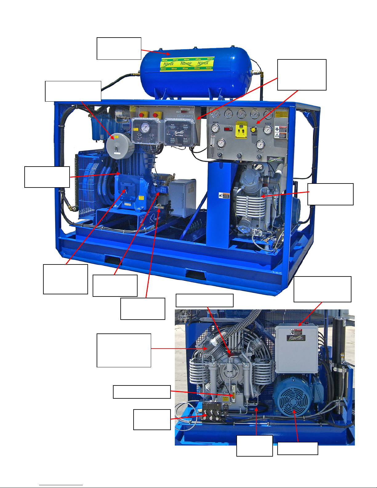
10.0 Q-390/MCH 36 Nitrox System Component Identification
LP Compressor
LP Oil Drain
LP Oil Filter
LP Oil
Compressor
Volume
LP Quincy
HP Coltri
HP Compressor
HP Auto
HP Oil
HP Oil Fill Port
HP Oil Gauge
HP Motor Control
HP Motor
Intake Filter
390
Check and
Fill Port
NUVAIR
Q-390/MCH36 Nitrox system User Manual
Tank
Intake Plumbed
to Membrane
Drains
Page
Q-390/MCH 36Electric Nitrox System
Control
Panels
MCH36
Electric Box
Drain
14

LP Feed Air
LP Motor
Box
Membrane
Heater
HP compressor
HP compressor
Condensate
Power cable for
LP Compressor
Electric
Volume
Tank
LP Electric Motor
HP & LP Collective
Ball Valve
filter canisters
Moisture
Separator
Container with
Muffler & Drain
total package
NUVAIR
Q-390/MCH36 Nitrox system User Manual
Q-390/MCH 36Electric Nitrox System
Control Electric
Page
15
Transformer
Filtration
(4 Stage)
Aftercooler
Condensate Drain
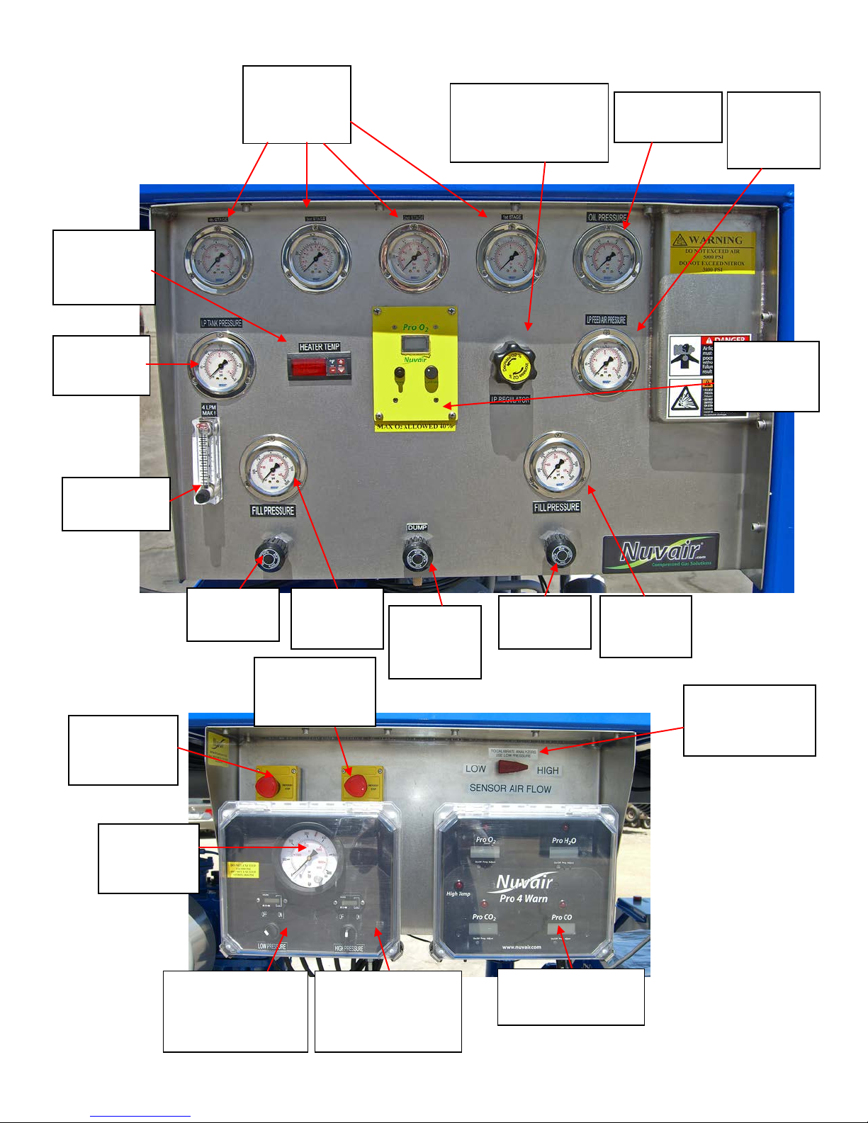
Control Panel
Stage
LP Back Pressure
2
Heater
Permeate
Fill
Gauge
HP Oil
On/Off
Membrane
Gauge
Fill
Gauge
On/Off
LP Tank
Gauge
Dump
Flow Meter
High Pressure
Low Pressure
Dial-A-
Emergency
Emergency
Pro 4 Warn
Gas flow switch
Pressure
Gauges
Thermostat
Control
Pressure
4LPM Max.
Valve
Stop HP
Compressor
Stop LP
Compressor
Pressure Fill
Gauge
Compressor
On/Off Switch &
Hour Meter
NUVAIR
Q-390/MCH36 Nitrox system User Manual
Pressure
Compressor On/Off
Switch & Hour
Meter
Valve for
O2%
Page
16
Q-390/MCH 36Electric Nitrox System
Regulator Adjustment
Knob - Adjust Nitrox
% Here
O
Valve
Multi Gas Monitor
Pressure
Pressure
Feed
Pressure
Oxygen
Analyzer
for Monitoring
LP or HP Gas

Q390/MCH36
Shown Within Dashed Lines
11.0 System Drawing / Schematic
nitrox system Components
Q-390/MCH 36Electric Nitrox System
NUVAIR
Q-390/MCH36 Nitrox system User Manual
Page
17
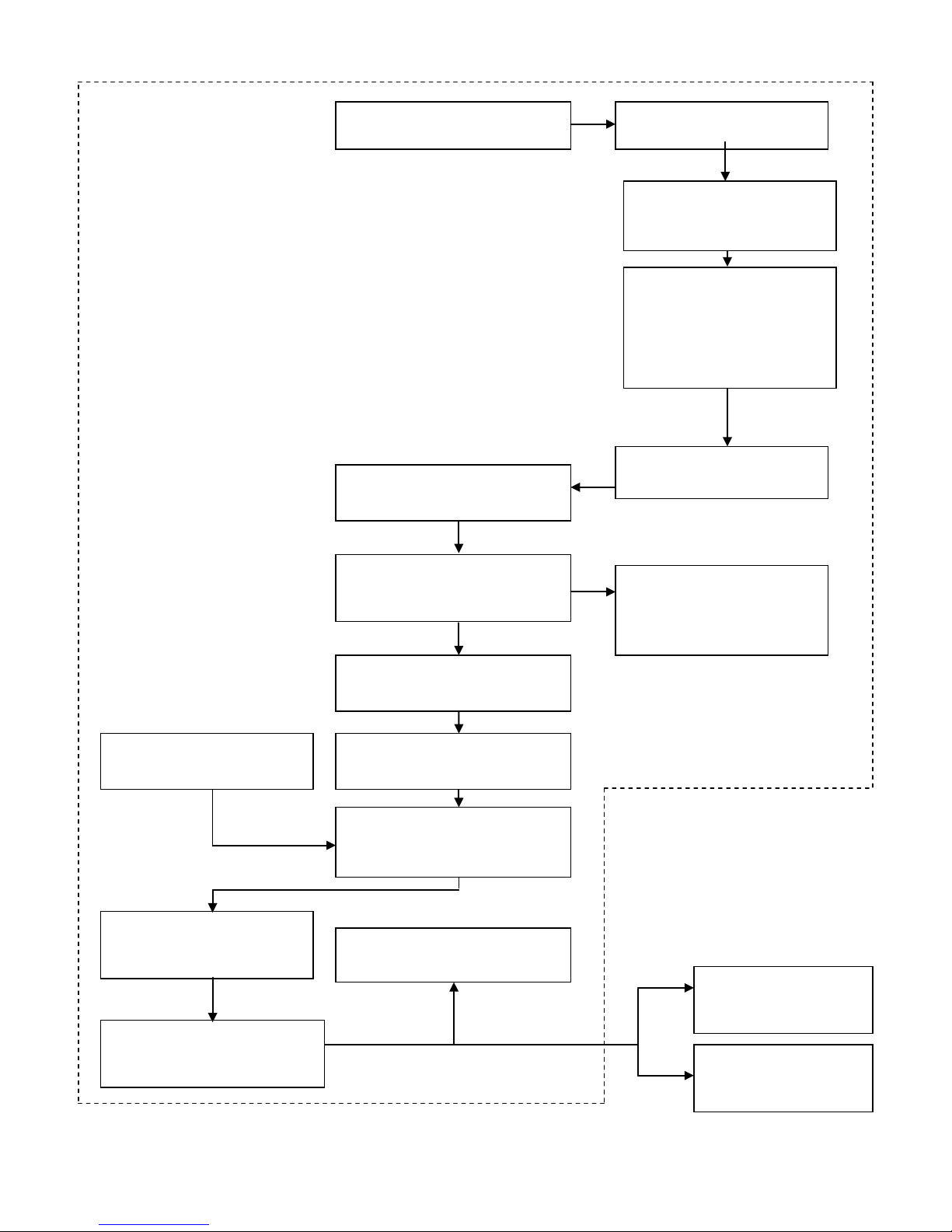
12.0 System Flow Chart
LP aftercooler removes
moisture
LP feed air filtration
B.P./ LP regulator controls
Desired Nitrox %
Thermostat controlled heater
Membrane separates supply
nitrogen rich gas
Permeate exits membrane
Nitrogen rich gas exits
Mixing tube mixes air &
Air intake delivers filtered
Permeate O2 analyzer
compression to +/- 2% O2
HP compressor with
compresses nitrox
Fill diver O2 analyzer monitors
HP nitrox delivered to
HP nitrox delivered to
- OR -
Optional vacuum pump or
LP compressor produces LP
feed air (supply air)
LP Volume Tank Collects
Nitrox system components
Q-390/MCH 36Electric Nitrox System
Moisture and Delivers
Feed Air
shown within dashed lines
the amount of feed air
pumped by the
compressor. Reducing
Pressure Adjusts to
heats air to 110ºF (43ºC)
produces Grade D air
air into permeate and
through fixed orifice
located by exhaust cooling
air vent
ambient air to mixing tube
blower
monitors nitrox before
moisture removal & filtration
NUVAIR
Q-390/MCH36 Nitrox system User Manual
permeate to create nitrox
18
2
containing 24-40% O
nitrox mixture to +/- 1% O2
Page
scuba cylinder
storage

Q-390/MCH 36Electric Nitrox System
13.0 Installing the Q-390/MCH36 Nitrox System
If any information in this manual conflicts with any of the other manuals call Nuvair before
proceeding.
The Nuvair System should never be operated in a facility where the room temperature exceeds
104o F (40o C) while the system is in use. Operation at higher temperatures may lead to system
damage and malfunction. A damaged membrane will not produce the correct nitrox mixture
which can lead to severe personal injury if the gas is used for diving purposes wi thout proper
analysis.
13.1 Precautions
1. Please read all information supplied before physically installing the nitrox system.
2. Unpack the system and remove from the pallet. Visually inspect the system to make sure there
has been no damage during shipping. If damaged, please call Nuvair to file a damage report.
Please take photos and supply detailed information about the damage.
3. Place the system in a location that allows a minimum spacing of 18 inches from adjacent walls.
Select a location where ambient room temperature will never exceed 104o F (40o C).
4. The heater thermostat has been set in the factory. Do not
adjust.
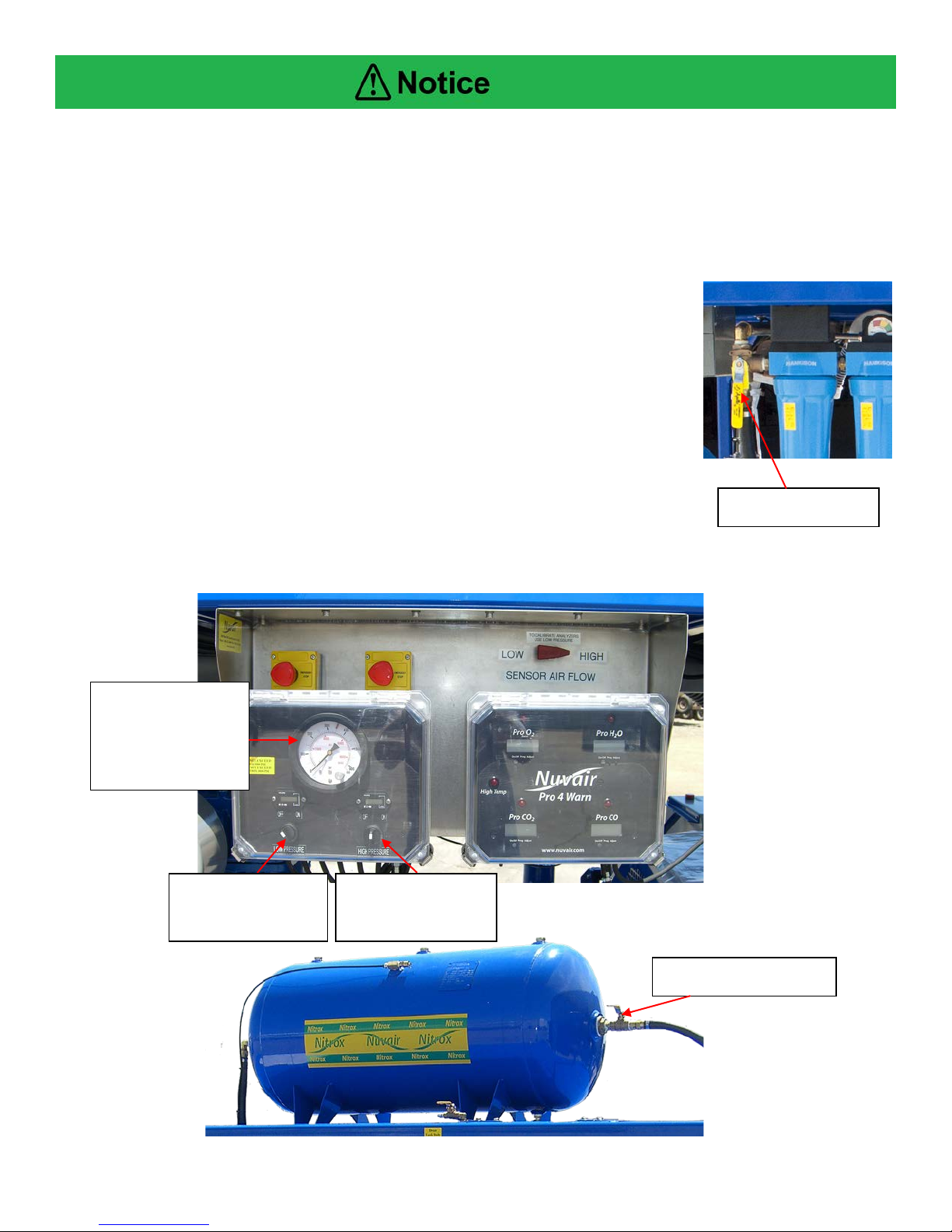
13.2 Attaching Nitrogen Discharge Hose (option)
The nitrogen discharge from the membrane on the system exits
at the fitting in the picture. The open frame should not require a
discharge hose, unless installed in an improperly
vented room.
Pure nitrogen is a colorless, odorless, tasteless gas that will not support life.
Breathing gas mixtures containing more than 84% nitrogen at surface
pressures will lead to unconsciousness and may cause death.
The nitrogen discharge from the membrane should be vented to a wellventilated room or to open air with good circulation. Failure to isolate the
discharge from the air intake of the membrane system or LP compressor could
lead to incorrect nitrox mixtures, resulting in se rious personal injury or death.
If you allow this pure nitrogen to accumulate in an enclosed space, anyone entering this
space will quickly lose consciousness and will die if not immediately resuscitated.
NUVAIR
Q-390/MCH36 Nitrox system User Manual
Page
19

Q-390/MCH 36Electric Nitrox System
HP On/Off
Switch
HP compressor Shown
LP Hour
Meter
HP Hour
Meter
LP On/Off
Switch
13.3 Electrical Power Connection
Never use extension cords to provide power to your nitrox system. The system
must be properly wired according to national and local electrical codes by a
qualified electrician. Improper wiring may lead to fires, which can cause serious
personal injury or death.
The electrical power to the Nuvair Nitrox System must be off while wiring this
system for service. Failure to ensure that the electrical power is off can lead to
severe personal injury and death by electrocution.
Prior to making the electrical power connection, check all system specifications provided in this
manual. When working on the nitrox system, the main breaker at the power source must be “locked
out” and “tagged out” in the “Off” position. The nitrox system has electrical protection for the
compressor Motor an d membrane system Heater located inside the motor starter compartment.
Amperage Load for System
♦ Approximately 54 Amps for 440 V three phase service
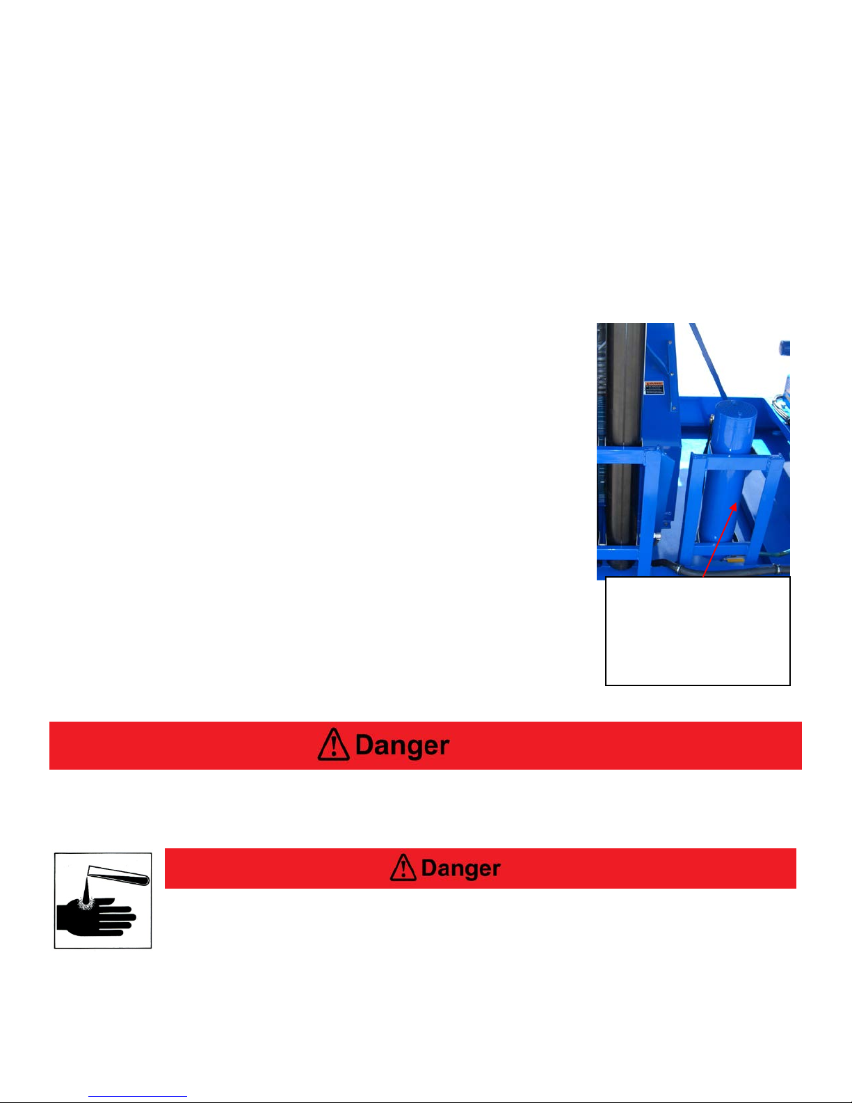
Compressor Rotation Check
Always turn on (bump) starter for both LP and HP compressors and run motor very briefly to check for
proper direction of rota ti on (see arrow on belt guar d and flywheel).
Note Proper Direction
of Rotation
Operation in reverse direction for extended periods of time will cause a reciprocating
compressor to run hot and perform poorly and may cause permanent damage. Reverse
rotation for a rotary screw compressor for even a short period of time will cause damage.
NUVAIR
Q-390/MCH36 Nitrox system User Manual
Page
20

HP
gauge
LP oil fill &
13.4 Check Compressor Lubricant Levels
Check lubricant levels before starting the LP
and HP compressors and add lubricant as
required. Use only the lubricants specified by
Nuvair.
Q-390/MCH 36Electric Nitrox System
dip stick
Compressor
lubricant
level sight
Do not allow nitrox to be discharged into the air storage system. Nitrox
introduced into the air storage system could cause a diver to suffer from oxygen
poisoning at depth. Oxygen poisoning is extreme ly dangerous and can lead to
death by drowning.
Do not allow air to be discharged into the nitrox storage system. Air introduce d into the nitrox
storage system could cause a diver to suffer decompression sickness if the nitrox mixture is
not analyzed properly and is used underwater under the assumption it is a different mix.
13.5 Control Panel Identification
See Page 16
NUVAIR
Q-390/MCH36 Nitrox system User Manual
Page
21

Q-390/MCH 36Electric Nitrox System
14.0 Pre-Operation Instructions
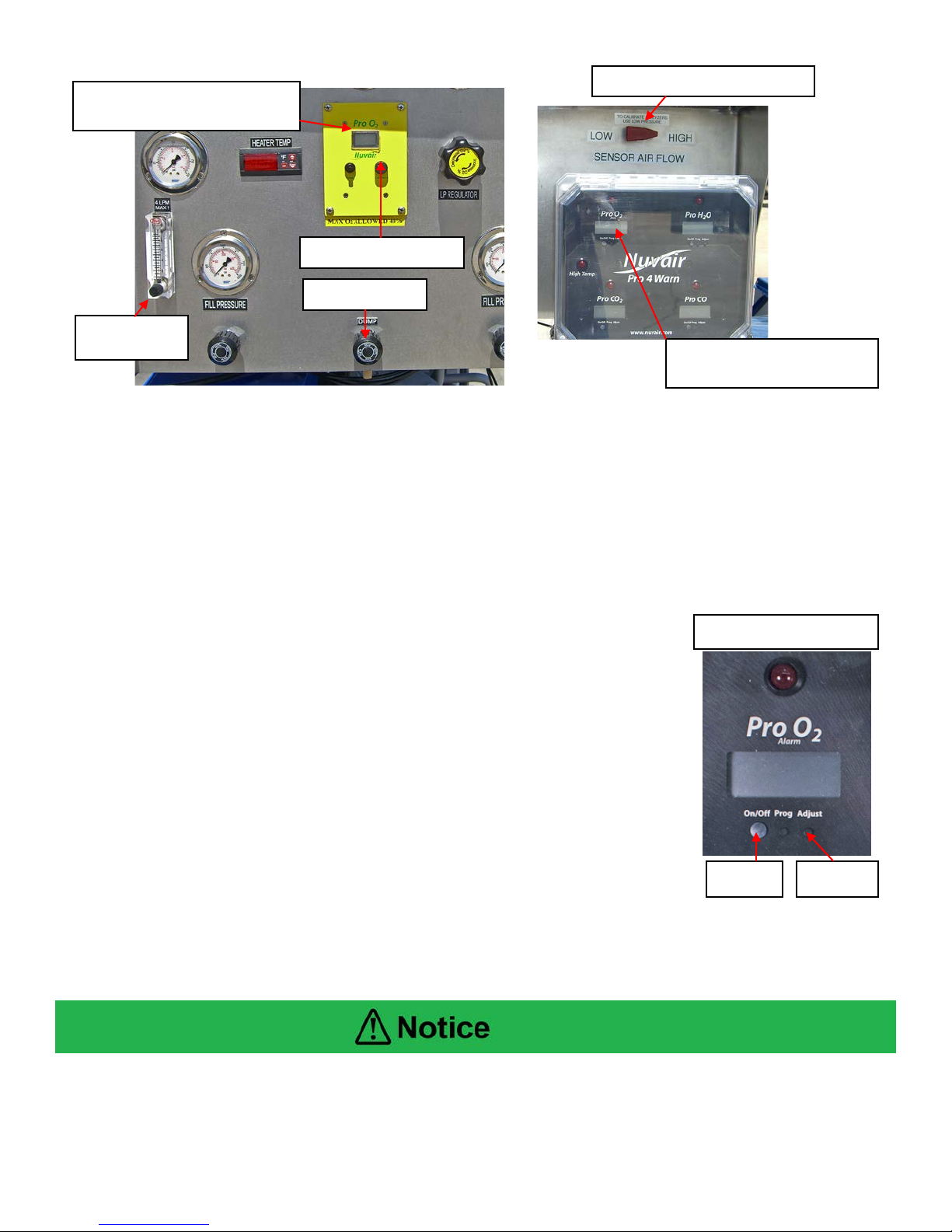
14.1 Calibrate Oxygen Analyzers
Gas production is monitored with the permeate oxygen analyzer before the compressed gas enters
the HP compressor to obtain a rough estimate of O2% (+/- 2%). Do not rely on this reading as a
proper indication of percentage of oxygen at the HP compressor outlet. Prior to pumping nitrox from
the compressor, it must be monitored with the fill oxygen analyzer to obtain a precise measurement of
O2% (+/- 1%). Both oxygen analyzers must be calibrated prior to each use.
Oxygen Analyzers must be calibrated before each use. See Oxygen Analyzer manuals for
correct calibration procedures. Improper calibration of the Fill Oxygen Analyzer may result in
the use of incorrect nitrox mixtures, which may cause serious injury or death to the diver
using the gas mixture.
At altitudes above sea level, a correction factor must be used when calibrating the fill oxygen
analyzer. It may not be possible to achieve all desired mixtures at altitude. See fill oxygen
analyzer manual for correcting analyzer readings at various altitudes. Imprope r calibration of
the fill oxygen analyzer may result in the use of incorrect nitrox mixtures, which may cause
serious injury or death to the diver using the gas mixture.
The permeate oxygen analyzer supplies oxygen readings that can vary +/- 2% O2 due to heat,
humidity, and pressure changes experienced in the nitrox flow and therefore should only be
used for rough estimates of O2%. The fill oxygen analyzer supplies more accurate oxygen
readings, within +/- 1% O2. For cylinder nitrox fills, the user must always verify the final fill
with a third independent oxygen analyzer.
NUVAIR
Q-390/MCH36 Nitrox system User Manual
Page
22
Q-390/MCH 36Electric Nitrox System
On/Off
Adjust
Fill Oxygen Analyzer
Calibration knob
Permeate oxygen analyzer
provides rough reading
Fill oxygen analyzer
provides precise reading
Low High Flow Valve
Dump Valve
Flow Meter
14.1 Calibrate Oxygen Analyzers - Continued
1) Turn on the high pressure compressor and analyzers.
2) Crack open the dump valve on the Control Panel so that the running HP compressor maintains
1500-2000 psi (100-136 bar) outlet pressure. Air will now be flowing past both oxygen
analyzers for calibration purposes; allow warm up 1-2 minutes.
3) Turn on low pressure compressor (make sure Feed air ball valve on tank is closed)
4) Monitor all gauges for proper operating range and check all connections for leaks.
5) Calibrate permeate oxygen analyzer while the HP compressor is pumping air. Refer to the
oxygen analyzer manual included with the nitrox system for details. Note that special
calibration procedures may be required when operating at altitudes above sea level.
6) Fill oxygen analyzer (Pro 4 Warn)
a. Open feed air ball valve on tank.
b. Change Low High Flow Valve on control panel to Low
c. Adjust flow meter to 4 LPM
d. Expose the sensor to ambient air for approximately 1-2
minutes.
e. Push the On/Off and Adjust buttons simultaneously to calibrate
fill analyzer.
f. Change Low High Flow Valve switch to High.
g. The fill oxygen analyzer is now ready for use.
Different settings may be used depending on heat, humidity and
altitude verify your actual ambient conditions and refer to
the oxygen analyzer manual for details.
7) Increase the low pressure compressor to a minimum of 90 psi
8) Allow the compressors to run for a 10 minute warm up period for
the membranes to warm up and stabilize. Check the heater
temperature gauge to verify air temperature rises and is between 105-120 ºF (40-49 ºC).
9) Now that the system temperature has stabili zed, you must recalibrate the fill O2 analyzer.
See step (6) above for cal i br ati on.
The oxygen analyzers may require re-calibration after 10-20 minutes of operation due to
humidity and temperature change effects on the sensor. To recalibrate, turn off the LP feed
air and follow calibration instructions.
NUVAIR
Q-390/MCH36 Nitrox system User Manual
Page
23
Q-390/MCH 36Electric Nitrox System
Fill oxygen analyzer
15.0 Producing Nitrox
Before using your nitrox system to pump nitrox, test a sample of the nitrox produced using the
air/nitrox quality analysis kit provided to verify compliance with CGA standards or applicable
standards for intended us e. Quarterly testing is mandatory once the system is operational.
The equipment you will be using to manufacture nitrox (oxygen rich air) will expose you to
both low and high-pressure gas. Gas, even under moderate pressures, can cause extreme
bodily harm. Never allow any gas stream to be directed at any part of your body.
Do not change the temperature setting on the thermostat control without contacting Nuvair.
Changes in temperature settings may cause membrane damage. A damaged membrane will
not produce the correct nitrox mixture which can lead to severe personal injury if the gas is
used for diving purposes without proper analysis.
15.1 Flow to Membrane and Setting Proper Pressure
The membrane system feed air pressure determines the oxygen percentage of the nitrox mixture. As
pressure is increased, a higher oxygen percentage of nitrox is pumped. As pressure is decreased, a
lower percentage of oxygen is pumped.
1) Increase pressure by slowly turning the back pressure LP regulator knob clockwise while
monitoring the LP pressure gauge and permeate oxygen analyzer. As the pressure rises, watch
the corresponding increase in the analyzer O
2) Increase or decrease pressure slowly until the permeate oxygen analyzer displays the percentage
of oxygen desired in the final nitrox mixture.
• Regulated membrane system pressure range should be
90– 175 psi (6-12 bar), depending on nitrox O2%being
produced.
• Heater temperature range should be 105-120º F (40-49º C).
15.2 Final Adjustments Before Pumping nitrox
1) As the nitrox initially makes its way through the running HP
compressor, the O2% reading on the fill oxygen analyzer will slowly
increase to read approximately the same O2% as the permeate
oxygen analyzer. This should happen within 3-5 minutes.
2) When the two analyzers read within +/- 1%, make any final
adjustments to the membrane system f eed air pressure necessary to
obtain the exact nitrox O2% desired as indicated on the fill oxygen
analyzer.
3) The system is now ready to pump nitrox.
4) Now you’re ready to close the dump valve and open the on/off fill
valve to the storage system.
% reading.
2
NUVAIR
Q-390/MCH36 Nitrox system User Manual
Page
24

Q-390/MCH 36Electric Nitrox System
The use of enriched air nitrox does not eliminate the risk of decompression sickness (DCS) in
diving. Decompression sickness can lead to permanent disability or death.
The permeate O2 analyzer supplies oxygen readings that can vary +/- 2% O2 due to heat,
humidity, and pressure changes in the nitrox flow and should only be used for rough
estimates of O2%. The fill O2 analyzer supplies more accurate readings, within +/- 1% O2. For
scuba cylinder fills, the user must always verify the fill with a third independent O2 analyzer.
Do not use this system to produce nitrox mixtures containing more than 40%
oxygen. Pumping nitrox mixtures with higher concentrations of oxygen may
lead to fires or explosions, which can cause serious personal injury or death.
Do not pump nitrox mixtures at pressures above the HP compressor rating, and
never above 3600 psi (250 bar). The system is not rated for pressures above
3600 psi (250 bar). Higher pressures may lead to explosions which may cause
serious personal injury or death.
No oxygen cleaning of standard cylinders or plumbing is mandatory when using the nitrox
system to produce nitrox containing a maximum of 40% oxygen. When filli ng oxygen clean
cylinders, hyper-purification of the nitrox is required using an optional oxygen compatible air
purification system available from Nuvair.
This nitrox system does not produce nitrox mixtures acceptable for 100%
oxygen service. Mixing nitrox mixtures with 100% pure oxygen may lead to fires
and / or explosions, which may cause serious personal injury or death.
Never fill a cylinder that is marked, “For Oxygen Service,” with nitrox that has
been produced by anything other than 100% oxygen clean system. Filling an
oxygen clean cylinder with breathing gas containing hydrocarbons can lead to
explosions if the cylinder is subsequently filled with gas mixtures containing gas mixtures
containing greater than 40% oxygen. Explosions may cause serious i nj ur y or death.
NUVAIR
Q-390/MCH36 Nitrox system User Manual
Page
25

Q-390/MCH 36Electric Nitrox System
Only provide scuba cylinder nitrox fills to customers who have proof of nitrox training and
certification. Improper use of nitrox can cause severe personal injury or death.
This system is not cleaned for oxygen service and not all components are
compatible with gas mixtures containing greater than 40% oxygen. Pumping
gas mixtures containing greater than 40% oxygen will lead to explosions which
may cause severe personal injury or death.
Each scuba cylinder belonging to a customer must be analyzed by tha t customer at the nitrox
filling facility, using an oxygen analyzer independent of those used with the nitrox system. An
employee must witness that the customer has properly analyzed the gas in each cylinder,
noted the maximum operating depth for that mi xture, and signed and dated the fill log. The
time of day must also be included with the date, since some customers may fill the same
cylinder more than once a day.
15.3 Pumping Nitrox
1) When filling a scuba cylinder, follow all industry standards. Do not exceed rated pressure of
cylinder, and do not exceed 360 0 psi (250 bar) under any condition.
2) With fill whip bleed valve open and nitrox flowing, verify that fill oxygen analyzer O2% reading
equals the desired nitrox O2%.
3) Close bleed valve, open cylinder valve, and fill cylinder. Monitor system for proper operation:
a) Monitor oxygen analyzers and recalibrate as required
b) Listen for proper operation of automatic condensate drains every 10-15 minutes.
c) Monitor all system gauges as shown in the table below.
The Oxygen Analyzers may require re-calibration after 10-20 minutes of operation due to
humidity and temperature change effects on the Sensor . To recalibrate, turn off the LP feed
air switch and follow calibration instructions.
When the HP compressor auto drain engages and dumps condensate, the fill oxygen analyzer
reading will decrease momentarily due to the pressure drop in the system. It will return to its
previous reading within seconds after the auto drain sequence stops.
NUVAIR
Q-390/MCH36 Nitrox system User Manual
Page
26

Q-390/MCH 36Electric Nitrox System
GAUGE
RECOMMENDED SETTING
Compressor Gauges
According to manufacturers recommendations
Heater Temperature
105 - 120o F (40 - 49o C)
Cabinet Temperature
Less than 100o F (38o C)
Membrane Feed Air Pressure
90 – 175 P.S.I. (6 - 12 bar) depending on Nitrox O2%
Fill Oxygen Analyzer
Showing the proper reading for intended fill
Nitrox Storage Pressure
DO NOT
exceed rating of tank or 3600 P.S.I (250 bar)
Use independent oxygen
15.3 Pumping Nitrox (continued)
4) Aft er filling is complete, close the cylinder valve, vent the bleed valve,
and remove the cylinder.
5) Test the nitrox O2% in the cylinder using an independent oxygen
analyzer such as the Nuvair O2 QuickstickTM. Calibrate the analyzer
before use in accordance with manufacturer’s instructions.
6) Repeat steps 1-5 until you have filled all scuba cylinders.
7) Mark each tank with fill date, O2%, fill pressure, and MOD
(Maximum Operating D epth) .
8) Log every nitrox fill to document the following information:
• Fill date and time of day
• Tank serial number
• Supplier’s check of oxygen content O2% plus signature and dat e
• User’s check of oxygen content O2% plus signature and date
• Fill pressure
• MOD (Maximum Operating Depth) in user’s handwriting
• Nitrox certifying agency and card number
9) When filling a HP nitrox storage tank, verify that fill oxygen analyzer O2% reading equals the
desired nitrox O2%. Open applicable line valves and tank valve, and fill with nitrox. Do not
exceed rated pressure of cylinder, and do not exceed 3600 psi (250 bar) under any condition.
After filling is complete, close all valves and allow nitrox system to shut down.
analyzer for verification
High-pressure cylinders that are filled quickly will become hot and due to the increased
internal temperature the cylinder pressure will increase. This will leave a diver with less
pressure inside the cylinder once cooling has occurred. This will decrease the amount of time
the diver may spend underwater which may be critical during a deep dive. Customers must be
warned of this possibility if cylinders are delivered for use while warm. Always fill all breathing
gas cylinders slowly to avoid overheating.
NUVAIR
Q-390/MCH36 Nitrox system User Manual
Page
27
Always use Oxygen Analyzers to monitor oxygen content of any gas flowing through the
High Pressure
Switch
Low Pressure
On/Off
Dial-A-Pressure
Ball Valve LP Tank
3 way Ball Valve
system. Both air and nitrox are subject to variations in oxygen content.
15.4 Pumping Air
To use the system to pump HP air, simply turn off the LP compressor and close ball valve on tank.
No nitrox will be supplied to the HP compressor, and it will pump air only. When the HP compressor
is pumping air, the permeate oxygen analyzer and the fill oxygen analyzer
should both read 20.9 O2%.
The LP compressor can pump Grade D breathing air only by turning the
three way valve to bypass the three stage breathing air filtration.
15.5 Shutting Down
1) When the storage banks are finished filling and tank valves are closed,
the nitrox system will automatically shut down at the pres sur e set on the
dial-a-pressure switc h ( 3600 psi) (250 bar).
2) Close ball valve on LP Tank
3) Turn off LP Compressor
4) The system will automatically drain all filters, compressor, and volume tank condensate.
Switch & Gauge.
Adjust Shut Off
Pressure Here
Compressor
NUVAIR
Q-390/MCH36 Nitrox system User Manual
Compressor On/Off
Page
Q-390/MCH 36Electric Nitrox System
28

Q-390/MCH 36Electric Nitrox System
16.0 Nitrox Operation Notes
• Ensure all personnel who operate the system are properly trained in its use.
• Keep a log with details of each cylinder filled with nitrox, including the time and date,
name of operator of system, name and certification number of diver, gas analysis,
MOD, and cylinder pressure.
16.1 Correlation of Feed Air Pressure to Oxygen Content
After the 10 hour break-in period for your nitrox system, you will notice that specific nitrox oxygen
percentages always match specific feed air pressures once the system has warmed up. These
pressures and percentages will be repeatable. If you find that the fill oxygen analyzer reads 36% O2
when the feed air pressure is at 125 psi (9 bar), record this pressure or make a mark on the feed air
pressure gauge indicating the O2%. Do this for each O2% that you normally make, making sure
system has warmed up first. The next time nitrox with 36% O2 is needed, adjust the regulator to 125
psi (9 bar) and wait for the oxygen analyzer reading to stabilize. You will find the analyzer reading to
be very close to 36% O2, requiring only minor adjustments of the regulator to achieve the exact
desired O2%.
Use the fill oxygen analyzer to verify the nitrox oxygen percentage prior to pumping. When
using the feed air pressure reading to obtain speci fic oxygen percentage, minor adjustments
of the feed air pressure regulator may be required to obtain the exact percentage desired.
16.2 Hot Fills
While in the process of filling HP nitrox storage tanks, you may have a need to supply a walk-in
customer with a scuba cylinder fill of a different nitrox mix. You can change mixes as follows:
1) With the nitrox system operating, isolate the HP nitrox storage tanks from the HP compressor by
closing the appropriate valves.
2) Record the membrane system feed air pressure reading.
3) Slightly open fill whip valve on the HP compressor, and adjust so the running compressor
maintains 1500-2000 psi (100-136 bar) outlet pressure.
4) Adjust the back pressure feed LP air regulator to the pressure corresponding to the desired nitrox
O2% for the scuba cylinder fill.
5) Allow the fill oxygen analyzer reading to stabilize, make any minor adjustments necessary to
achieve the desired O2%, and then fill cylinder in normal manner.
6) When finished retur n LP regulator to previous setting, and allow the fill oxygen analyzer reading to
stabilize. Make any minor adjustments necessary to achieve the desired O2%, and then resume
filling storage tanks.
NUVAIR
Q-390/MCH36 Nitrox system User Manual
Page
29

Q-390/MCH 36Electric Nitrox System
Condensate Drain
Check & Drain Weekly
17.0 Maintenance
The following list of daily and routine maintenance items is intended as a guide. Refer to LP and HP
compressor manuals for complete maintenance requirements.
17.1 Daily Maintenance
Be sure to check compressor lubricant levels prior to each day of operation. Failure to ensure
the proper lubricant level will lead to system damage.
1) Check lubricant levels of both LP and HP
compressors and add proper lubricants as
required. See Section 17.3 and compressor
manuals for details.
2) Slightly open each HP and LP manual condensate
drain valve to verify that no condensate is present.
3) Check LP air filtration for condensate and
proper operation of condensate drains.
Container.
Use only the specified Nuvair lubricants in this system. The use of
incompatible lubricants presents a risk of fire and/or explosion, and may resul t
in system damage. This can lead to severe personal injury and death.
Be sure that all pressure has been relieved from the system prior to opening
any filtration canister. Failure to vent pressure from the system prior to opening
the canister can lead to serious personal injury or death.
If system is located in an area where there is high humidity and high heat, the life of all
filtration elements may be as little as 35% of rated operating capacity. Check the compressor
manual and appendix for details on filter element life factors.
NUVAIR
Q-390/MCH36 Nitrox system User Manual
Page
30
Q-390/MCH 36Electric Nitrox System
Condensate drain
as needed.
17.2 Routine Maintenance
1) LP Compressor Lubricant: Change compressor lubricant every 100 hours or annually, whichever
comes first. Only use lubricants rated for use wit h nitrox, such as Nuvair 455 TM. Never mix
compressor lubricants. See Section 17.3 and LP compressor manual for details.
2) HP Compressor Lubricant: Change compressor lubricant every 100 hours or annually, whichever
comes first. Only use lubricants rated for use with nitrox, such as Nuvair 455 TM. Never mix
compressor lubricants. See Section 17.3 and HP compressor manual for details.
3) LP Air Filtration Inspection: On a weekly basis, inspect each filter bowl for the presenc e o f
moisture and each Element for any unus ual degradation or wetness. See Section 17.5 for details.
4) LP Air Filtration Elements: Change LP filter elements every 100 hours or annually to maintain
CGA Grade D air standards. Visual liquid level and service life indicators assist w i th moni t or i ng
replacement intervals. See Section 17.5 for details. If the nitrox system is operated in high
humidity and/or high temperature, filter elements must be changed mor e o ften. See appendix for
details on filter element life factors.
5) HP compressor Filtration Element: Change HP Filter Element
every 60,000 cubic feet (about 50 hours) of air or nitrox
processing to maintain CGA Grade E air standards. See
Section 17.7 for details. If the nitrox system is operated in high
humidity and/or high temperature the filter element must be
changed more often. See appendix for details on filter element
life factors.
6) Condensate Drain Container with valve open: Chec k level of
attached bucket and drain weekly or as needed.
7) Semi-Permeable Membrane: No maintenance required.
Service life exceeds 20 years if LP air filtration is properly
serviced to maintain oil free Grade D air standards.
8) Membrane System Air Intake Filter: Inspect filter element
every 3 months for visible particles. Change every 12 months
or sooner if particles are visible.
9) Oxygen Analyzers: Replace oxygen sensor and battery as
required. See manual included with nitrox system.
10) Air/nitrox Quality Analysis: Take breathing air/nitrox samples quarterly
for analysis to assure compliance with CGA Grade E breathing air s tand ar ds .
container must be
attached to a drain bucket
and left open. Check and
drain the bucket weekly or
Do not swallow (ingest) either the electrolyte from the oxygen sensor or the sensor itself. The
Potassium Hydroxide chemical contained in the sensor can cause severe injury or death. If
electrolyte or the Sensor is swallowed, seek medical attention immediately.
If after handling the oxygen analyzer or sensor, you find that your fingers or
other parts of your body feel “slippery” or the skin or eyes sting, immediately
flush affected area with clean, fresh water for at least 15 minutes. The stinging
or slippery sensation is an indication of a leaking Sensor. The Potassium
Hydroxide chemical contained in the sensor can cause severe injury or death. Seek immediate
medical attention if eye contact is made or skin stinging persists.
NUVAIR
Q-390/MCH36 Nitrox system User Manual
Page
31

Q-390/MCH 36Electric Nitrox System
Use only the specified Nuvair lubricants in this system. The use of
incompatible lubricants presents a risk of fire and/or explosion, and may result
in system damage. This can lead to severe personal injury or death.
17.3 Compressor Lubricants (see page 40 for Material Safety Data Sheets)
• The LP compressor in your nitrox system comes standard with Nuvair 455 synthetic food
grade compressor lubricant. Customers may specify different lubricants, check lubricant
page at the back of manual for accepted lubricants.
• The HP compressor comes with the Nuvair 455 synthetic food grade lubricant. Customers
may specify different lubricants, check lubricant page at the back of manual for accepted
lubricants.
• Check lubricant levels at sight gauge on HP and dip stick of LP Compressor and add
lubricant as required through the appropriate lubricant fill plug.
• Lubricant is removed through the drain plugs. See LP and HP compressor manu al s for
details on servicing lubricant
Never mix different lubricants together because equipment damage may occur when
machinery is operated with improper lubricant.
Do not carry out any maintenance tasks if the compressor has just shut down.
Wait for the compressor to cool to avoid skin burns.
Pressure must be properly drained from the system before opening the LP fill
plug. Failure to drain pressure may result in severe personal injury.
Any oil spilled during the oil and oil filter change coul d cause personnel to slip
and fall. Wear anti-slip footwear. Remove any traces of spilled oil immediately.
Slips and falls may cause severe personal injury or death.
Wear eye protection, gloves, and skin protection whe n performing
oil changes. Although the oil is not classified as a dangerous
substance, the oil can be irritating to your eyes and skin.
Both oil and oil filter are classified as “special wastes” and must be disposed
of properly according to applicable na tional and local laws. Failure to dispose
of these wastes properly can lead to death of wildlife as well as government
fines and penalties.
NUVAIR
Q-390/MCH36 Nitrox system User Manual
Page
32

Lubricant fill plugs
HP compressor
LP compressor
Lubricant drain plugs, right side of pumps
Lubricant sight gauge
Lubricant dip stick
All maintenance work must be carried out with the compressor off and the
power supply lead unplugged from the main socket. Appropriate steps must be
taken to tag out and lock out the electrical power. Failure to isolate this
equipment from the power source while performing maintenance may result in
severe personal injury or death.
• The LP compressor in your nitrox system comes standard with Nuvair 455 synth et ic food
grade compressor lubricant.
• The HP compressor comes with the Nuvair 455 synthetic food grade lubricant.
• Check lubricant levels at sight gauge on HP compressor and dip stick on LP compressor,
add lubricant as required through the appropriate lu br i cant fill plug.
• Lubricant is removed through the drain plugs. See LP and HP compressor manu als for
details on servicing .
NUVAIR
Q-390/MCH36 Nitrox system User Manual
Page
Q-390/MCH 36Electric Nitrox System
33

Q-390/MCH 36Electric Nitrox System
HF1-24
HF5-24
HF7-24
HF11-24
Replacement Element Part Number
E1-24
E5-24
E7-24
E11-24
Air Flow
HF5-24
Housing
Element inside bowl
HF1-24
moisture
HF7-24
Bowl
HF11-24
17.4 LP Feed Air Filtration and Bowls
Special attention needs to be given to the arrangement of the four LP feed air filtration
elements and bowls. Properly reinstall each element and bowl to the correct housing.
Improper sequence can cause damage to downstream components
The use of Grade D or better feed air is critical to prevent the passing of any residual oil vapor into
the membrane system. Four stages of Hankison LP filtration are used to produce Grade D air:
1) Coalescing filter (HF11-24)
2) Coalescing & water/oil vapor removal to 1 Particulate micron (HF7-24)
3) Coalescing & water/oil vapor removal to 0.01 Particulate micron (HF5-24)
4) Fina l s tage - oil vapor removal to 0.003 PPM (HF1-24)
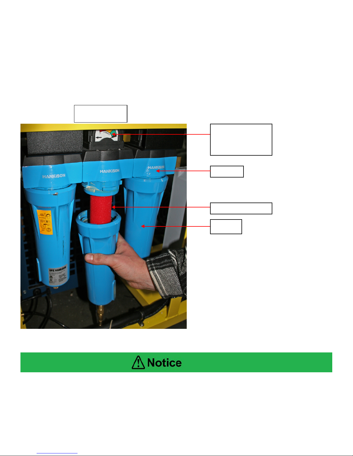
17.5 LP Filtration Inspection
Open each Filter and inspect as follows:
Inspect the bowl for the presence of moisture. A high level of moisture build-up in the HF11-24 or
HF7-24 filter indicates improper operation of auto-drain floats. Evidence of any moisture in the
HF1-24 filter indicates air is not cooling properly and moisture is not properly being removed.
Check HF1 canister weekly for moisture. Moisture indicates possibl e aut o drai n problem. Excess
moisture will prevent the final filter from operating properly and can lead to damage of the
membrane.
Filter with
auto-drain
should not
contain
NUVAIR
Q-390/MCH36 Nitrox system User Manual
Filter with
auto-drain
float & liquid
level indicator &
service indicator
Filter with
auto-drain
float & liquid
level indicator &
service indicator
Page
34
Filter with
auto-drain
float & liquid
level indicator
Q-390/MCH 36Electric Nitrox System
Changing LP
filtration element
Housing
Element inside bowl
Bowl
Differential pressure
should be changed
17.6 Changing LP Filtration Elements
Change filtration elements every 100 hours. If the nitrox system is operated in high humidity and / or
high temperature, filter elements must be changed more often. See appendix for details on filter
element life factors. Visual service indicators on the HF7 & HF5 filters assist with monitoring
replacement intervals.
1) Push up on filter bowl, rotate counter-clockwise, and lower to remove.
2) Gently unscrew filter element and pull down off mounting post.
3) Replace filter element and reassemble bowl in reverse order.
indicators. Color
indicates when filter
The interior of the Filter Bowls can be cleaned with a diluted solution of Simple GreenTM and
flushed thoroughly with clean water. This will assist to prolong the life of the element, bowl,
and auto drain.
NUVAIR
Q-390/MCH36 Nitrox system User Manual
Page
35
Q-390/MCH 36Electric Nitrox System
Filter canisters
3 4 5
Condensate Drain
Check & Drain Weekly
2) Manual Bleed Valve
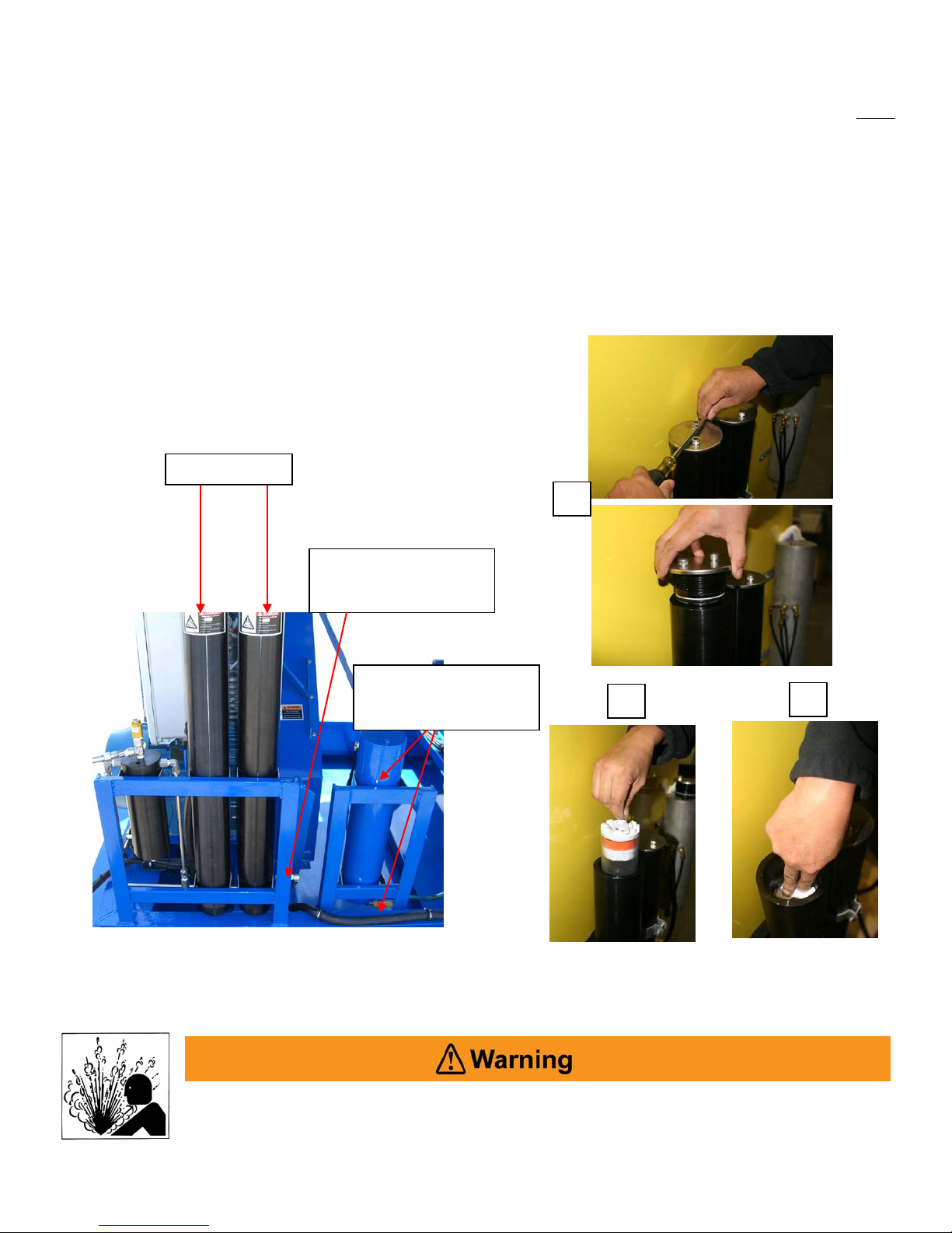
17.7 HP Compressor Filtration
The HP compressor comes standard with triplex filtration, utilizing a single filter element. Do NOT
use any substitute. Change filtration elements every 60,000 cubic feet (about 50 hours) of air or nitrox
processing. If the nitrox system is operated in high humidity and / or high temperature, filter elements
must be changed more often. See appendix for details on filter element life factors.
1) Shut down the nitrox system
2) Open manual bleed drain valve to drain pressure. Leave valve open.
3) Unscrew the filter canister cap.
4) Remove expended element from filter canister.
5) Install new element place pressure on element to seat the element.
6) Reinstall cap to canister.
7) Close manual condensate valves.
at base of tower.
Container.
Be sure that all pressure has been relieved from the system prior to opening
any filtration canister. Failure to vent pressure from the system prior to opening
the canister can lead to serious personal injury or death.
NUVAIR
Q-390/MCH36 Nitrox system User Manual
Page
36

Q-390/MCH 36Electric Nitrox System
Nitrox System Components
Type
Part Number
LP Compressor Consumables
Hankison HF11-24
E11-24
Hankison HF7-24
E7-24
Hankison HF5-24
E5-24
Hankison HF1-24
E1-24
HP Compressor Consumables
HP compressor lubricant, food
grade, nitrox compatible
Breathing air filter, Grade E
X65247
Heater assembly
2400 Watt, 28" length
H2400
220V Fahrenheit gauge
220V Centigrade gauge
Heater pressure switch
B16-947
Pro O2 Remote
9462
Pro O2 Remote
9506
1-1/4"-1-1/2" to 1-1/2"
RDTC40X32
Related Equipment Components
Specify: (1) CGA Grade
required
18.0 Spare Parts List
See LP and HP compressor manuals for compressor parts lists. Other nitrox system components
and related items are listed below.
LP compressor lubricant, food
grade, nitrox compatible
Nuvair 455, 1 Gal 9406
LP filtration elements
Nuvair 455, 1 Gal 9406
Gas drying filter X65677
HP compressor filtration elements
Heater thermostat control
(standard)
TS-13020 F
TS-13021 C
Membrane 250 Series PPA250
Air intake filter element 10-20 CFM 18P
Mixing tube assembly 2 in diameter, specify length Call for price
Oxygen analyzers
Oxygen sensors
Compressor hose couplers
Air / nitrox quality analysis kit
NUVAIR
Q-390/MCH36 Nitrox system User Manual
Pro 4 Warn Pro4Warn
1-1/4"-1-1/2" to 1-1/4"-1-1/2" 018578000476
(2) Single use or program Use
Page
37

19.0 Service Record Log
Date
Technician Name
Service Performed
Q-390/MCH 36Electric Nitrox System
NUVAIR
Q-390/MCH36 Nitrox system User Manual
Page
38

Q-390/MCH 36Electric Nitrox System
Item
Grade D
Grade E
O.C.A
Oxygen
19.5-23.5%
20-22%
20-22%
Carbon Dioxide (maximum)
1000 PPM
1000 PPM
1000 PPM
Carbon Monoxide (maximum)
10 PPM
10 PPM
2 PPM
Hydrocarbons (maximum)
Not specified
25 PPM
25 PPM
Water Vapor (maximum) (3)
67 PPM
67 PPM
67 PPM
Dew Point (maximum) (1)
-50ºF
-50ºF
-50ºF
Oil & Particles (maximum) (2 )
5 mg/m3
5 mg/m3
5 mg/m3
Odor
None
None
None
Filter
Temperature
Ambient
Temperature
Filter Element
Life Factor
53ºF (12ºC)
41ºF (5ºC)
2.6 x Life
62ºF (17ºC)
50ºF (10ºC)
1.8 x Life
71ºF (23ºC)
59ºF (16ºC)
1.35 x Life
80ºF (27ºC)
68ºF (20ºC)
1 x Life
89ºF (32ºC)
77ºF (25ºC)
0.8 x Life
96ºF (36ºC)
84ºF (29ºC)
0.55 x Life
105ºF (41ºC)
93ºF (34ºC)
0.45 x Life
114ºF (46ºC)
102ºF (39ºC)
0.35 x Life
20.0 Appendix
20.1 Supply and Breathing Air Specifications
All supply and breathing air must meet the following requirements of CGA G-7.1-1997. Supply air
delivered to the membrane system must be purified to meet oil f ree Grade D, Grade E, or O.C.A. as
specified below and periodic air quality testing to assure compliance is mandatory. All breathing air
for diving produced by the downstream compressor must be purified to meet Grade E quality, and
periodic air quality testing to assure compliance is mandatory.
Notes: (1) Dew Point of supply air must be >10
o
F (6oC) colder than coldest ambient air expected
(2) Supply air delivered to the membrane system must contain <0.003 PPM Oil Vapor
(3) May Vary with intended use.
All breathing nitrox produced for diving must be purified to meet these same requirements, except for
oxygen content. Nitrox oxygen content must measure within +/- 1% O2 of the specified value of the
mixture using a properly calibrated oxygen analyzer (i.e. nitrox produced with a target content of 32%
O2 must measure in the range of 31-33% O2). Periodic air quality testing to assure compliance is
mandatory.
20.2 Filter Element Life Factors
Breathing air filter element life is typically rated by manufacturer based on an air temperature of 80ºF
at the filter inlet. Under normal operation this temperature is 12ºF (5ºC) warmer than the ambient air,
resulting in an equivalent ambient temperature rating at 68ºF (20ºC).
To determine element life at a different ambient temperature, multiply the rated life by the life factor
listed below:
NUVAIR
Q-390/MCH36 Nitrox system User Manual
Page
39

Q-390/MCH 36Electric Nitrox System
OWNER’S WARRANTY RESPONSIBILITIES
Failure of the owner to prevent equipment damage by complying with the procedures outlined below and in the
operation manual will void the nitrox system warranty.
Installation:
• All set up requirements and procedures provided in the nitrox system operation manual must be
followed in their entirety including supply air cleanliness, compressor preparation, and installation of the
nitrox system.
• Supply air to the membrane must be properly filtered to oil free CGA Grade D air quality or better to
prevent damage to the membrane. Air quality testing of the supply air should be performed periodically
and documented to assure compliance.
• If there is any doubt regarding the suitability of a HP or LP compressor for compressing nitrox, contact
Nuvair or the compressor manufacturer before you connect your nitrox system.
• If an existing HP or LP compressor is to be used for compressing nitrox, all traces of the old lubricant
must be removed and replaced with a nitrox compressor lubricant approved by Nuvair.
• Electrical wiring and connections should be made by a qualified electrician in accordance with all
national and local electrical codes.
• Do not change the temperature setting on the heater thermostat control. Changes in temperature
settings may cause membrane damage.
• To prevent compressor damage, only use the compressor Intake Hose provided. If a longer hose is
required, contact Nuvair for assistance.
• Compressors must be provided adequate ventilation to operate properly and prevent heat damage.
This requires an ambient temperature below 104
and proper rotation direction.
Operation:
• Do not use the nitrox system to supply a HP or LP compressor with nitrox mixtures containing more
than 40% oxygen. Compressing higher concentrations of oxygen may cause severe compressor
damage.
• Do not pump nitrox mixtures at pressures above the compressor manufacturer’s rating, and never
above 3600 psi (250 bar). Compressing nitrox at higher pressures may cause severe HP compressor
damage.
• To prevent membrane damage, drain all low pressure filters and condensate tanks on a daily basis.
• If you become aware of an operational fault, stop using the equipment immediately and contact Nuvair
for assistance.
Maintenance:
• Change low pressure filter elements on a schedule determined by filter capacity and ambient
temperature and humidity. Contact Nuvair if you need assistance establishing a schedule for your
equipment and location.
• Replace membrane system air intake filter on a regular basis to prevent flow obstruction.
• Keep all nuts, bolts, fittings, connectors, and clamps tight.
• Keep a service record book showing that regular maintenance work has been carried out. If a warranty
claim becomes necessary, it will aid in demonstrating that damage has not been caused by insufficient
maintenance. Proof of maintenance may be required prior to determining the validity of a warranty
request.
o
F (40 o C), sufficient clearance from adjacent walls,
NUVAIR
Q-390/MCH36 Nitrox system User Manual
Page
40

NUVAIR NITROX SY STEM WARRANTY
NUVAIR extends a limited warranty, which warrants the nitrox system to be free f rom defects in materials and
workmanship under normal use and service for a limited period. The specific membrane component of the
nitrox system is warranted according to the pro-rated t erms as set forth below. All other Original Equipment
Manufacturer (OEM) components used in the system are warranted only to the extent of the OEM’s warranty to
NUVAIR. NUVAIR makes no warranty with respect to these OEM components, and only warrants the
workmanship that NUVAIR has employed in the installation or use of any OEM component. This warranty is
not transferable.
NUVAIR will, at its discretion and according to the terms as set forth within, replace or repair any materials
which fail under normal use and service and do not exhibit any signs of improper maintenance, misuse,
accident, alteration, weather damage, tampering, or use for any other than the intended purpose.
Determination of failure is the responsibility of NUVAIR, which will work together with the customer to
adequately address warranty issues. When any materials are repaired or replaced during the warranty period,
they are warranted only for the remainder of the original warranty period. This warranty shall be void and
NUVAIR shall have no responsibility to repair or replace damaged materials resulting directly or indirect ly from
the use of repair or replacement parts not approved by NUVAIR.
Pro-Rated Terms:
NUVAIR warrants the membrane component of the nitrox system to be free from defects in material and
workmanship for a period of thirty-six (36) months from date of installation or forty-two (42) months from date of
shipment by NUVAIR, whichever may occur first. The warranty covers parts only and is prorated as follows:
• First Year Repair or replacement free of charge
• Second Year Warranty allowance of 70% of the current membrane component list price
• Third Year Warranty allowance of 40% of the current membrane component list price
A warranty registration card, supplied with system documentation, must be filled out and submitted to NUVAIR
for the warranty to be in full effect. If the warranty registration card is not received within thirty (30) days of
installation, the thirty-six (36) month warranty will begin with the date of shipment from NUVAIR. For warranty
service to be considered, customer’s account must be current or paid in full.
Maintenance Items:
Any materials which are consumed, or otherwise rendered not warrantable due to processes applied to them,
are considered expendable and are not covered under the terms of t his policy. T his includes maintenance and
consumable items listed as part of a suggested maintenance program included with system documentation.
Return Policy:
Application for warranty service can be made by contacting NUVAIR during regular business hours and
requesting a Return Material Authorization (RMA) number. Materials that ar e found to be defective must be
shipped, freight pre-paid, to the NUVAIR office in Oxnard, California. Upon inspection and determination of
failure, NUVAIR shall exercise its options under the terms of this policy. Warranty serviced materials will be
returned to the customer via NUVAIR’s preferred shipping method, at NUVAIR’s expense. Any expedited
return shipping arrangements to be made at customer’s expense must be specified in advance.
Limitation of Warranty and Liability:
Repair, replacement or refund in the manner and within the time provided shall constitute NUVAIR’S sole
liability and the Purchaser’s exclusive remedy resulting from any nonconformity or defect. NUVAIR shall not in
any event be liable for any damages, whether based on contract, warranty, negligence, strict liability or
otherwise, including without limitation any consequential, incidental or special damages, arising with respect to
the equipment or its failure to operate, even if NUVAIR has been advised of the possibility thereof. NUVAIR
makes no other warranty or representation of any kind, except that of title, and all other warranties, express or
implied, including warranties of merchantability and fitness for a particular purpose, are hereby expressly
disclaimed. No salesman or other representative of NUVAIR has authority to make any warranties.
NUVAIR
Q-390/MCH36 Nitrox system User Manual
Page
Q-390/MCH 36Electric Nitrox System
41

Q-390/MCH 36Electric Nitrox System
Change Date
Description of Change
Additional Record of Changes
It is the responsibility of the owner of this product to register their ownership with Nuvair by
sending the warranty card provided to Nuvair. This card is to establish registration for any necessary
warranty work and as a means of communication that allows Nuvair to contact the user regarding this
product.
The user must notify Nuvair of any change of address by the user or sale of the product. All
changes or revisions to this manual must be recorded in this document to ensure that the manual is
up to date.
NUVAIR
Q-390/MCH36 Nitrox system User Manual
Page
42

Q-390/MCH 36Electric Nitrox System
Q-390/MCH 36Electric Nitrox System
Nuvair
Phone +1 805 815 4044
Fax +1 805 486 0900
1600 Beacon Place
Oxnard, CA 93033 USA
info@nuvair.com
www.nuvair.com
 Loading...