

Page 1
READ & SAVE THESE INSTRUCTIONS!
OPERATING INSTRUCTIONS
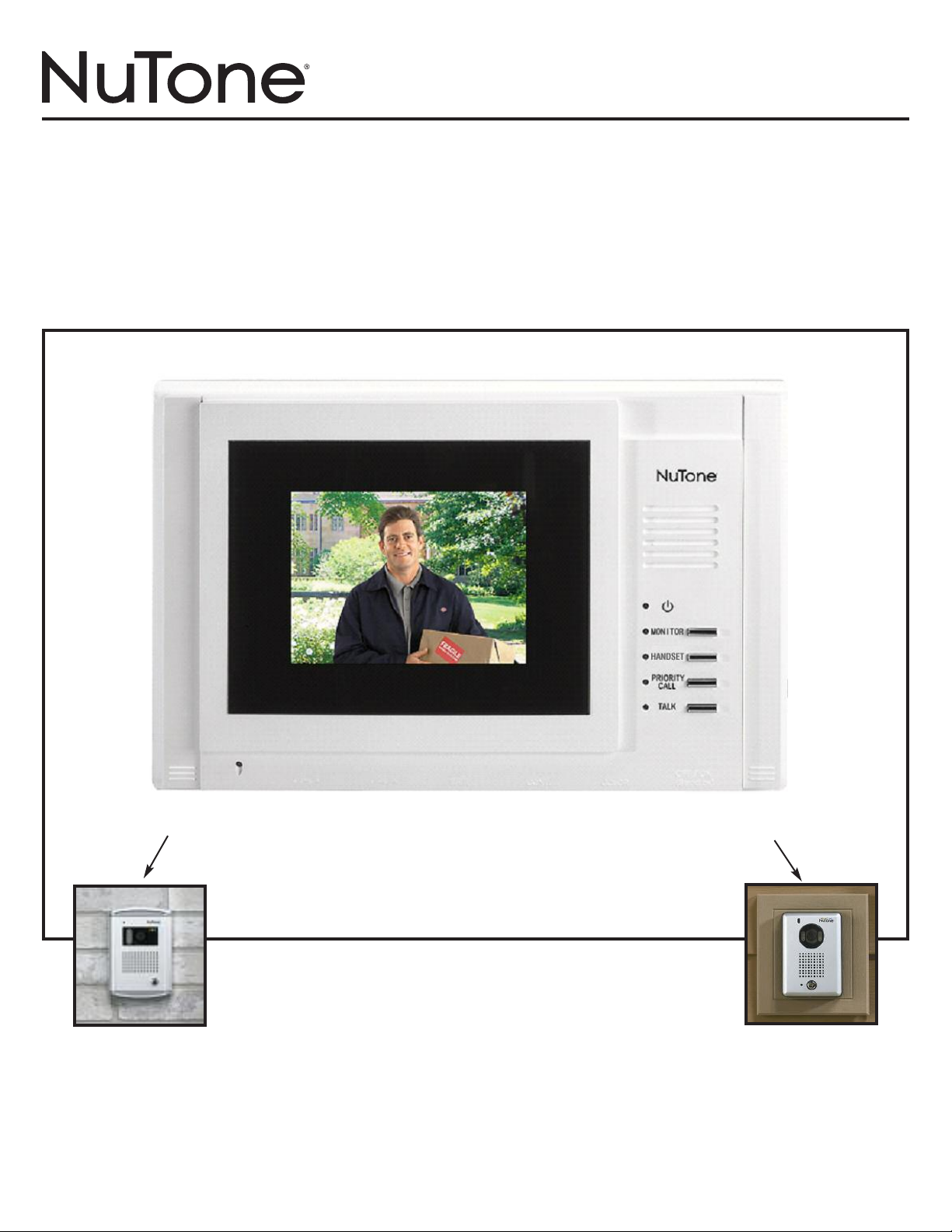
Video Door Answering System
Model VSM4RK / VSM4SK
HOMEOWNERS
OPERATING INSTRUCTIONS
IMPORTANT
This product has many functions and controls. Please read entire operating instructions before using this product.
VSM4RK VSM4SK
VSC4R
Recessed Mount
TO REGISTER THIS PRODUCT, VISIT WWW.NUTONE.COM
VSC4S
Surface Mount
Page 2
Caution
RISK OF ELECTRIC SHOCK
DO NOT OPEN
AUTION: TO PREVENT THE RISK OF ELECTRIC SHOCK, DO NOT
C
EMOVE COVER (OR BACK). NO USER-SERVICEABLE
R
PARTS INSIDE. REFER SERVICING TO QUALIFIED
SERVICE PERSONNEL.
WARNING: TO REDUCE THE RISK OF FIRE OR ELECTRIC SHOCK,
DO NOT EXPOSE THIS APPARATUS TO RAIN OR
MOISTURE.
THE APPARATUS SHALL NOT BE EXPOSED TO DRIPPING
OR SPLASHING AND NO OBJECTS FILLED WITH LIQUIDS,
SUCH AS VASES, SHALL BE PLACE ON THE APPARATUS
EXPLANATION OF GRAPHICAL SYMBOLS
The lightning flash with arrowhead, within an equilateral triangle, is intended to alert the user to the presence of
uninstalled “dangerous voltage” within the product’s enclosure. This voltage may be of sufficient magnitude to
constitute a risk of electric shock to persons.
The exclamation point within an equilateral triangle is intended to alert the user to the presence of important
operating and maintenance (servicing) instructions in the literature accompanying the appliance.
IMPORTANT SAFETY INSTRUCTIONS
1) Read these instructions.
2) Keep these instructions.
3) Heed all warnings.
4) Follow all instructions
5) Do not use this apparatus near water.
6) Clean only with dry cloth.
7) Do not block any ventilation openings. Install in
accordance with the manufacturer’s instructions.
8) Do not install near any heat sources such as radiators,
heat registers, stoves, or other apparatus (including
amplifiers) that produce heat.
Do not defeat the safety purpose of the polarized or
9)
grounding-type plug. A polarized plug has two blades
with one wider than the other. A grounding type plug has
two blades and a third grounding prong. The wide blade
or the third prong are provided for your safety. If the
provided plug does not fit into your outlet, consult and
electrician for replacement of the obsolete outlet.
10) Protect the power cord from being walked on or pinched
particularly at plugs, convenience receptacles, and the
point where they exit from the apparatus.
11) Only use attachments/accessories specified by the
manufacturer.
12) Unplug the apparatus during lighting storms or when
unused for long period of time.
13) Refer all servicing to qualified service personnel.
Servicing is required when the apparatus has been
damaged in any way
is damaged, liquid has been spilled or objects have
fallen into apparatus, the apparatus has been exposed
to rain or moisture, does not operate normally, or has
been dropped.
, such as power-supply cord or plug
Date of Purchase
Dealer Purchased From
Address
s
Dealer
Dealer’s Phone No.
Model No. & Serial No.
’
2
Page 3
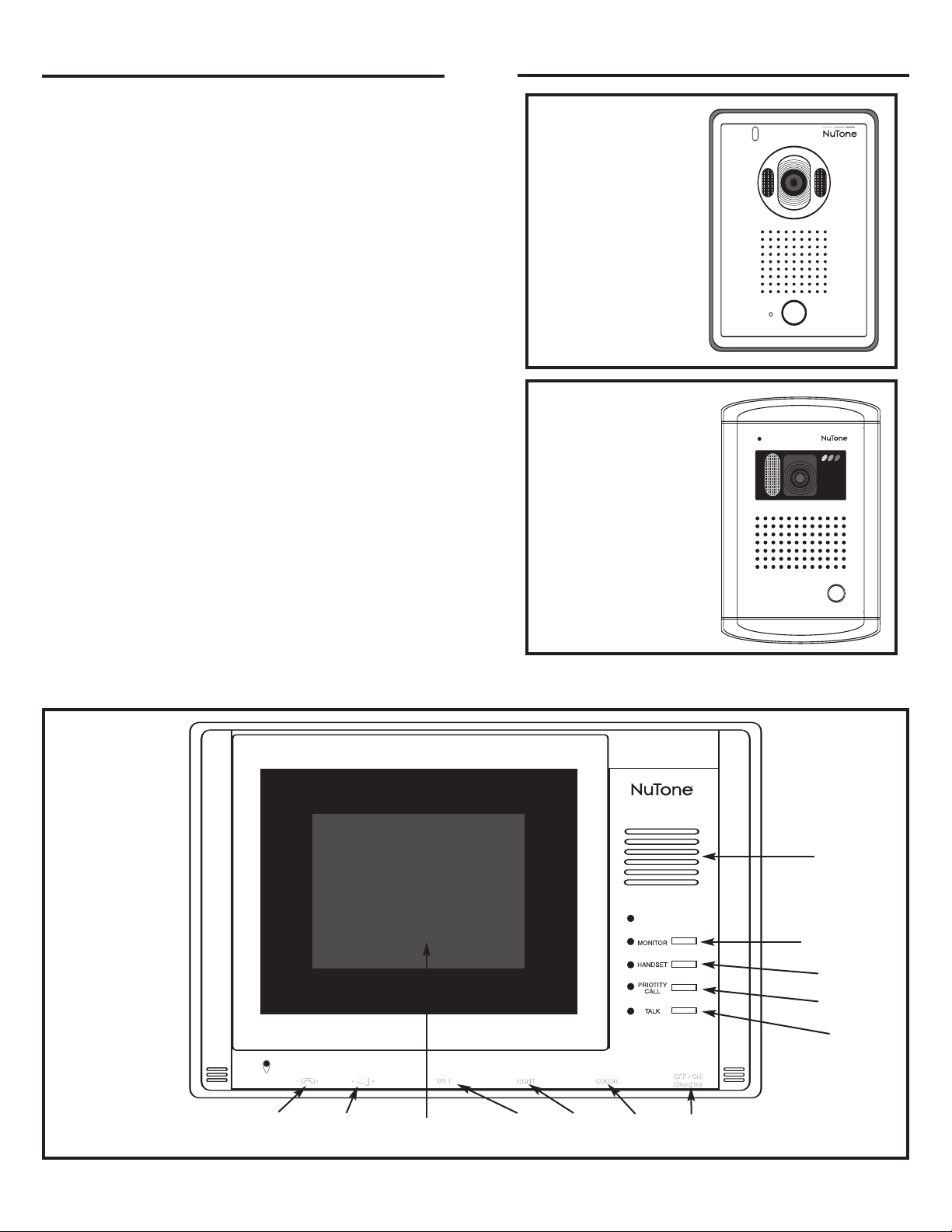
Table of Contents
Illustration of Model VSM4 Monitor . . . . . . . . . . . . . .3
Monitor Station Controls . . . . . . . . . . . . . . . . . . . . . .4
onitor Controls . . . . . . . . . . . . . . . . . . . . . . . . . . . . .4
M
Intercom Volume Control . . . . . . . . . . . . . . . . .4
hime Volume Control . . . . . . . . . . . . . . . . . . .4
C
Brightness Control . . . . . . . . . . . . . . . . . . . . . .4
Contrast Control . . . . . . . . . . . . . . . . . . . . . . . .4
Color Control . . . . . . . . . . . . . . . . . . . . . . . . . .4
On/Off/ Standby Control . . . . . . . . . . . . . . . . . .4
Monitor Operation . . . . . . . . . . . . . . . . . . . . . . . . . . . .4
Monitor Button . . . . . . . . . . . . . . . . . . . . . . . . .4
Handset Button . . . . . . . . . . . . . . . . . . . . . . . .4
Priority Call Button . . . . . . . . . . . . . . . . . . . . . .4
alk Button . . . . . . . . . . . . . . . . . . . . . . . . . . . .4
T
Optional Handset Operation . . . . . . . . . . . . . .5
Camera Operation . . . . . . . . . . . . . . . . . . . . . .5
Ending Door Call . . . . . . . . . . . . . . . . . . . . . . .5
Video Timeout . . . . . . . . . . . . . . . . . . . . . . . . .5
Resetting the Monitor . . . . . . . . . . . . . . . . . . . . . . . . .5
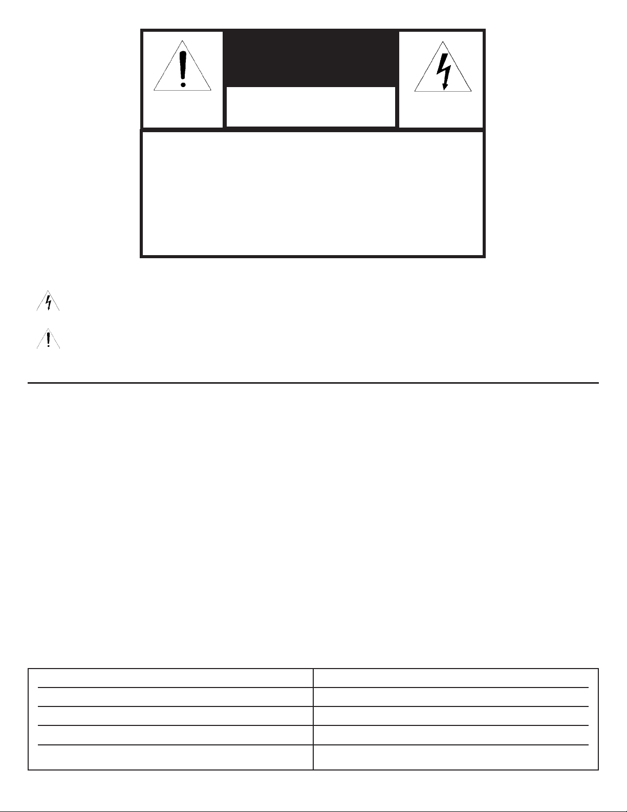
Illustrations of Cameras
SC4S
V
VSC4R
Camera Volume Adjustment . . . . . . . . . . . . . . . . . . . .5
Camera Lens Adjustment . . . . . . . . . . . . . . . . . . . . . .5
Warranty . . . . . . . . . . . . . . . . . . . . . . . . . . . . . . . . . . . .6
Illustrations of Model VSM4 Monitor
Speaker
Monitor
Handset
Priority
Call
alk
T
Intercom
olume
V
Chime
Volume
LCD Display
Brightness Contrast Color
3
On/Off
Stand by
Page 4

Monitor Controls
Intercom Volume Control
The slide control switch for this volume control is located on the left front edge of the bottom of the VSM4 Monitor. This control
switch is moved to the left to decrease the volume level of the intercom. It is moved to the right to increase the volume level of the
intercom.
Chime Volume Control
The slide control switch for this volume control is located on the left middle front edge of the bottom of the VSM4 Monitor. This
control switch is moved to the left to decrease the chime volume level on the VSM4. It is moved to the right to increase the chime
volume level on the VSM4.
Brightness Control
The slide control switch for this brightness control is the left most middle located controls located on the middle front edge of the
bottom of the VSM4 Monitor. This control switch is moved to the left to decrease the brightness of the display level on the VSM4.
It is moved to the right to increase the brightness level on the VSM4.
Contrast Control
The slide control switch for this contrast control is the right most middle located controls located on the middle front edge of the
bottom of the VSM4 Monitor. This control switch is moved to the left to decrease the contrast of the display level on the VSM4. It is
moved to the right to increase the contrast level on the VSM4.
Color Control
The slide control switch for this color control is located on the right middle front edge of the bottom of the VSM4 Monitor. This color
switch is moved to the left to decrease the color level on the VSM4. It is moved to the right to increase the color level on the VSM4.
ON / OFF / Standby Control
The slide control switch for this on / off / standby control is located on the right front edge of the bottom of the VSM4 Monitor. This
control switch is moved to the left to turn off the power to the monitor. It is moved to the right to turn on the power to the monitor.
Monitor Operation
Monitor Button
This button is used to activate the camera that will display on the monitor the video image captured. Details for button and system
operation below;
Press the “Monitor Button”.
• Camera activates (Powers on).
• Picture displays on monitor (no audio).
Press “Talk Button” to establish audio between monitor and camera locations.
* If optional handset (VSA4S) is lifted while audio established between monitor and camera, it also will
now have audio established to those devices.
If “Monitor Button” is left on, it will turn off after 60 seconds.
Monitor mode may be terminated by pressing “Monitor Button” turning off the “red monitor” LED.
Handset Button
This button is used together with the
Press the “Talk Button” then press the “Handset Button”.
• Ring tone beep will be generated at the optional handset each time the “Handset Button” is pressed.
• Once the handset is lifted, audio communication is established between the handset and the monitor location.
Priority Call Button
This button is used together with the Talk Button and Monitor Button to disable the microphone at the camera. Normal use would
be to cut out unwanted outside noise during conversation heard at the main unit.
Press the “Talk Button” and the “Monitor Button”.
• Lift the optional handset (VSA4S) to initiate all three calling devices
• Press the “Priority Call Button”.
The camera microphone is disabled so no audio communication will be heard while the “Priority Call Button” is
active.
Audio and video remain normal at the monitor and the handset retains normal audio communication.
Talk Button
This button is used for all audio communications.
If this button is activated (red
• If the optional handset is lifted, audio communication is established between the handset and the monitor
To turn off the “Talk and the Talk LED” , Press the “Talk Button” and any communication is terminated.
T
Talk Button to activate the beep tone at the optional handset (VSA4S).
alk LED remains on) it will remain on indefinitely
4
.
.
Page 5

ptional Handset Operation (VSA4S)
O
Lift handset and depress “Call Button” on handset.
• Monitor must have “Talk Button” activated for audio communication to be established between handset and monitor.
Camera Operation
Press “Call Button” on camera.
• Video turns on at monitor.
“Talk Button” at monitor must be pressed to initiate audio between camera and monitor.
•
• If handset is lifted, audio communication between the camera and handset is established.
Ending the Door Call
Once audio and video communication is established between the camera and the monitor, press the “Monitor and Talk Buttons” so
that each red LED turns off. Audio and video communications will be terminated.
Video Timeout
The video will deactivate the camera and turn off the display after 60 seconds, unless manually turned off by pressing the
“Monitor Button”.
Resetting the Monitor
This is performed by turning the On / Off / Standby switch to the leftmost position to power down the product. Wait a minimum of
30 seconds prior to moving the On / Off switch to the “On” position to power the monitor.
Camera Volume Adjustment
The VSC4R and VSC4S door cameras are provided with a
volume level adjustment set screw. The adjustment has been
pre-set at the factory to provide the optimal volume level at
the door camera. The volume level can be adjusted if your
specific application requires the level to be either increased or
decreased. Insert a jeweler’s screwdriver into the small hole
that is shown in the camera illustration. Rotate the small set
screw to adjust the volume level.
Important: Do not use excessive force to rotate the screw.
Damage could occur to the camera, and loss of audio may
result. Use extreme caution when making the adjustment. Do
not use a screwdriver that is too big for the application.
VSC4R
Volume Adjustment
VSC4S
Volume
Adjustment
Lens
VSC4R
Adjustment
VSC4S
Lens
Adjustment
Camera Lens Manual
Adjustment
The VSC4R and VSC4S door cameras are provided
with a manual camera lens adjustment. The adjustment
can be used to fine tune the angle of the camera lens
to compensate for installations that are not directly in
line to the viewing area.
the back of the camera, as shown in the camera
illustration. Move the adjustment control upward to
lower the camera lens. Move the adjustment control
downward to raise the camera lens. Adjust the camera
lens position to provide the best viewing area for your
installation.
lens to the sides.
5
The VSC4R camera will also adjust the
The adjustment is located on
Page 6

FCC Information Part 15 Rules
This equipment has been tested and found to comply with the limits for a Class B digital device, pursuant to Part 15 of the FCC
Rules. These limits are designed to provide reasonable protection against harmful interference in a residential installation.
This equipment generates, uses and can radiate radio frequency energy and, if not installed and used in accordance with the
nstructions may cause harmful interference to radio communications. However, there is no guarantee that interference will not
i
occur in a particular installation. If this equipment does cause harmful interference to radio or television reception, which can be
determined by turning the equipment off and on, the user is encouraged to try to correct the interference by one or more of the
following measures:
• Reorient or relocate the receiving antenna
• Increase the separation between the equipment and receiver
• Connect the equipment into an outlet on a circuit different from that to which the receiver is connected.
• Consult the dealer or an experienced radio/TV technician for help.
FCC Warning – This equipment may generate or use radio frequency energy. Changes or modifications to this equipment may
cause harmful interference unless the modifications are expressly approved in the instruction manual. The user could lose the
authority to operate this equipment if an unauthorized change or modification is made.
FCC Warning – Changes or modifications not expressly approved by the party responsible for compliance could void the user’s
authority to operate the equipment.
The serial number of this product may be found on the rear side of the product. No others have the same serial numbers as yours.
You should record the number and other vital information here and retain this book as a permanent record of your purchase to aid
identification in case of theft.
Product specifications subject to change without notice.
4820 Red Bank Road, Cincinnati, Ohio 45227
Printed in Korea, 05/2006, Part No. 100913
Page 7

LISEZ ET CONSERVEZ CES DIRECTIVES!
DIRECTIVES DE FONCTIONNEMENT
Portier vidéo électronique
Modèle VSM4RK / VSM4SK
DIRECTIVES DE FONCTIONNEMENT
À L’INTENTION DU PROPRIÉTAIRE
IMPORTANT
Ce produit est doté de plusieurs fonctions et réglages. Veuillez lire ces directives de fonctionnement en entier avant d’utiliser ce produit.
VSM4RK VSM4SK
VSC4R
Recessed Mount
POUR ENREGISTRER CE PRODUIT, VISITEZ WWW.NUTONE.COM
VSC4S
Surface Mount
Page 8

Avertissement
RISQUE DE CHOC ÉLECTRIQUE
NE PAS OUVRIR
AVERTISSEMENT: POUR PRÉVENIR LE RISQUE DE DÉCHARGE
ÉLECTRIQUE, NE PAS RETIRER LE COUVERCLE (NI
LA PLAQUE DE DERRIÈRE). NE CONTIENT AUCUNE
PIÈCE POUVANT TRE RÉPARÉE PAR L’UTILISATEUR.
CONFIER TOUTE RÉPARATION À UN TECHNICIEN
PROFESSIONNEL.
MISE EN GARDE: POUR RÉDUIRE LE RISQUE DE DÉCHARGE
SIGNIFICATION DES SYMBOLES GRAPHIQUES
Le symbole “éclair” doté d’une tête de flèche et contenu dans un triangle équilatéral signale à l’utilisateur la présence
d’une zone de “tension dangereuse” dans le boîtier de l’appareil non installé. Cette tension est suffisamment élevée
pour soumettre les personnes à un risque de décharge électrique.
Le point d’exclamation contenu dans un triangle équilatéral signale à l’utilisateur des renseignements importants
dans ce manuel relativement au fonctionnement et à l’entretien (réparation) de l’appareil.
ÉLECTRIQUE, NE PAS EXPOSER CET APPAREIL À LA
PLUIE OU À L’HUMIDITÉ.
L’APPAREIL NE DOIT PAS TRE EXPOSÉ AU RUI
SELLEMENT NI À DES ÉCLABOUSSURES D’EAU, ET
DOIT TRE INSTALLÉ À L’ÉCART DE TOUT CONTENANT DE LIQUIDE, TEL QU’UN VASE.
IMPORTANTES CONSIGNES DE SÉCURITÉ
1) Veuillez lire ces directives.
2) Veuillez conserver ces directives.
3) Obéissez à toutes les mises en garde.
4) Suivez toutes les directives.
5) N’utilisez pas cet appareil à proximité de l’eau.
6) Nettoyez cet appareil avec un chiffon sec uniquement.
7) N’obstruez aucune prise de ventilation. Installez cet appareil
conformément aux directives du fabricant.
8)
Installez l’appareil à l’écart de toute source de chaleur, telle
que des radiateurs, convecteurs, poêles ou autres appareils
(y compris les amplificateurs) qui produisent de la chaleur.
9) N’apportez aucune transformation au dispositif de sécurité
d’une fiche polarisée ou à prise de terre. Une fiche polarisée
est pourvue de deux lames, dont l’une est plus large que
l’autre. Une fiche à prise de terre est pourvue de deux lames
et d’une tige de prise de terre. La lame plus large et la tige
de prise de terre de ces fiches sont des dispositifs de sécu-
rité. S’il est impossible d’insérer la fiche fournie dans votre
prise, demandez à un électricien de remplacer votre prise
devenue obsolète.
10) Le cordon d’alimentation doit être disposé de telle façon qu’il
soit impossible de marcher dessus ou de le coincer,
particulièrement à proximité des fiches, des prises de courant
et de son point de sortie de l’appareil.
11) Utilisez uniquement des périphériques et des accessoires
compatibles spécifiés par le fabricant.
12) Débranchez l’appareil pendant les orages ou lorsque celui-ci
ne doit pas être utilisé pendant une longue période de temps.
13) Confiez toute activité de réparation de l’appareil à un
technicien professionnel. Quelque soit le dommage subi,
l’appareil doit être confié à un technicien professionnel aux
fins de réparation (fiche ou cordon d’alimentation
endommagé, pénétration de liquide ou d’un corps étranger
dans l’appareil, exposition de l’appareil à la pluie ou à
l’humidité, fonctionnement anormal, appareil échappé).
Date de l’achat
Nom du détaillant
Adresse du détaillant
Node téléphone du détaillant
Node modèle et node série
2
Page 9

Table des matières
Illustration du moniteur VSM4 . . . . . . . . . . . . . . . . . .3
Réglages de station du moniteur . . . . . . . . . . . . . . . .4
Réglages du moniteur . . . . . . . . . . . . . . . . . . . . . . . . .4
églage du volume de l’intercom . . . . . . . . . . .4
R
églage du volume de la sonnette . . . . . . . . . .4
R
Réglage de la brillance . . . . . . . . . . . . . . . . . . .4
Réglage du contraste . . . . . . . . . . . . . . . . . . . .4
Réglage des couleurs . . . . . . . . . . . . . . . . . . . .4
Réglage marche/arrêt/attente . . . . . . . . . . . . . .4
Fonctionnement du moniteur . . . . . . . . . . . . . . . . . . .4
Touche moniteur . . . . . . . . . . . . . . . . . . . . . . . .4
Touche combiné . . . . . . . . . . . . . . . . . . . . . . . .4
Touche appel prioritaire . . . . . . . . . . . . . . . . . . .4
Touche conversation . . . . . . . . . . . . . . . . . . . . .4
Fonctionnement du combiné en option . . . . . . .5
Fonctionnement de la caméra . . . . . . . . . . . . .5
Fin d’appel porte . . . . . . . . . . . . . . . . . . . . . . . .5
Temporisation vidéo . . . . . . . . . . . . . . . . . . . . .5
Réinitialisation du moniteur . . . . . . . . . . . . . . . . . . . .5
Illustrations des caméras
SC4S
V
VSC4R
Réglage du volume de la caméra . . . . . . . . . . . . . . . .5
Réglage de la lentille de la caméra . . . . . . . . . . . . . .5
Garantie . . . . . . . . . . . . . . . . . . . . . . . . . . . . . . . . . . . . .6
Illustration du moniteur VSM4
Haut-parleur
Moniteur
Combiné
Appel
prioritaire
Conversation
Volume de
l’intercom
Volume de
la sonnette
Écran
ACL
Brillance Contraste Couleurs
3
Marche/arr
êt/attente
Page 10

Réglages du moniteur
Réglage du volume de l’intercom
L’interrupteur à glissière du réglage du volume est situé sur le bord avant gauche dans le bas du moniteur VSM4. Déplacez cet interrupteur à glissière vers la gauche pour diminuer le volume de l’intercom. Déplacez-le vers la droite pour augmenter le volume de l’intercom.
Réglage du volume de la sonnette
L’interrupteur à glissière du réglage du volume est situé sur le bord avant, entre l’extrémité gauche et le centre, dans le bas du moniteur
VSM4. Déplacez cet interrupteur à glissière vers la gauche pour diminuer le volume de la sonnette du VSM4. Déplacez-le vers la droite
our augmenter le volume de la sonnette du VSM4.
p
Réglage de la brillance
L’interrupteur à glissière du réglage de la brillance (BRT.) est situé sur le bord avant, pratiquement au centre à partir de l’extrémité
gauche, dans le bas du moniteur VSM4. Déplacez cet interrupteur à glissière vers la gauche pour diminuer la brillance d’affichage du
VSM4. Déplacez-le vers la droite pour augmenter la brillance d’affichage du VSM4.
Réglage du contraste
L’interrupteur à glissière du réglage du contraste (CONT.) est situé sur le bord avant, pratiquement au centre à partir de l’extrémité
droite, dans le bas du moniteur VSM4. Déplacez cet interrupteur à glissière vers la gauche pour diminuer le contraste d’affichage du
VSM4. Déplacez-le vers la droite pour augmenter le contraste d’affichage du VSM4.
Réglage des couleurs
L’interrupteur à glissière du réglage des couleurs (COLOR) est situé sur le bord avant, entre l’extrémité droite et le centre, dans le bas
du moniteur VSM4. Déplacez cet interrupteur à glissière vers la gauche pour diminuer la densité des couleurs du VSM4. Déplacez-le
vers la droite pour augmenter la densité des couleurs du VSM4.
Réglage marche/arrêt/attente
L’interrupteur à glissière marche/arrêt/attente (On/Off/Standby) est situé sur le bord avant droit, dans le bas du moniteur VSM4.
Déplacez cet interrupteur à glissière vers la gauche pour mettre le moniteur hors tension. Déplacez-le vers la droite pour mettre le moniteur sous tension.
Fonctionnement du moniteur
Touche moniteur
Cette touche permet d’activer la caméra et d’afficher sur le moniteur l’image vidéo saisie par la caméra. Les détails du fonctionnement
de cette touche et du système se trouvent ci-dessous. Appuyez sur la touche moniteur (Monitor).
• La caméra est activée (mise en marche).
• L’image vidéo apparaît sur le moniteur (aucun son).
Appuyez sur la touche conversation (Talk) pour activer la transmission audio entre le moniteur et les emplacements de
caméra.
* Si un combiné en option (VSA4S) est compris dans l’installation, il suffit de soulever le combiné alors que la
transmission audio est activée entre le moniteur et la caméra pour activer la transmission audio entre ces
périphériques et le combiné.
Si la touche moniteur (
ble de désactiver le mode moniteur en appuyant sur la touche moniteur (Monitor); le voyant à DEL rouge du moniteur
s’éteint.
Touche combiné (Handset)
Cette touche, utilisée en combinaison avec la touche conversation (T
alk
T
la touche conversation (
moniteur (Monitor).
• Le combiné en option émet une tonalité chaque fois que vous enfoncez la touche combiné (Handset).
Lorsque le combiné est soulevé, la transmission audio est activée entre le combiné et l’emplacement du moniteur
•
Touche appel prioritaire (Priority Call)
Cette touche, utilisée en combinaison avec la touche conversation (T
caméra. Elle sert habituellement à couper les bruits indésirables lors d’une conversation au moyen de l’unité principale.
• Soulevez le combiné en option (VSA4S) pour activer les trois périphériques d’appel.
• Appuyez sur la touche appel prioritaire (Priority Call).
Le microphone de la caméra est désactivé; par conséquent, la transmission audio est coupée lorsque la touche appel
prioritaire (Priority Call) est activée.
La transmission audio et vidéo est activée pour le moniteur et la transmission audio est activée pour le combiné.
ouche conversation (T
T
Cette touche sert à transmettre toutes les communications audio.
Lorsqu’elle est activée (le voyant rouge DEL
Si le combiné en option est soulevé, la transmission audio est activée entre le combiné et le moniteur
•
), puis appuyez sur la touche combiné (Handset).
alk)
Monitor) demeure activée, le moniteur s’éteint au bout de 60 secondes. Il est également possi-
alk
), active la tonalité du combiné en option (VSA4S). Appuyez sur
conversation (Talk
Appuyez sur la touche conversation (Talk
alk
) et la touche moniteur (Monitor), désactive le microphone de la
) demeure allumé), elle le demeure indéfiniment.
.
) et sur la touche
.
4
Page 11

our désactiver la fonction conversation et le voyant DEL conversation, appuyez sur la touche conversation (
P
cations sont coupées.
Fonctionnement du combiné en option (VSA4S)
oulevez le combiné et enfoncez la touche d’appel (Call) du combiné.
S
• La touche conversation (Talk) du moniteur doit être activée pour que la communication audio puisse être établie entre le
combiné et le moniteur.
Fonctionnement de la caméra
Appuyez sur la touche appel de la caméra.
• Appuyez sur la touche d’appel (
• La touche conversation (Talk) du moniteur doit être enfoncée pour activer la transmission audio entre la caméra et le
moniteur.
• Si le combiné est soulevé, la transmission audio est activée entre la caméra et le combiné.
Fin d’appel porte
Une fois que la transmission audio a été activée entre la caméra et le moniteur, appuyez sur les touches moniteur (Monitor) et con-
versation (Talk) pour éteindre les voyants DEL correspondants. Toutes les transmissions audio et vidéo sont coupées.
Temporisation vidéo
La transmission vidéo est désactivée sur la caméra et l’image vidéo cesse d’être affichée après 60 secondes, à moins d’avoir
d’abord été désactivées manuellement en appuyant sur la touche moniteur (
Réinitialisation du moniteur
La réinitialisation du moniteur s’effectue comme suit: glissez l’interrupteur marche/arrêt/attente (On/Off/Standby) à la position située à
l’extrême gauche. Attendez au moins 30 secondes, puis glissez l’interrupteur marche/arrêt/attente (On/Off/Standby) en position de mise
en marche (
On) du moniteur.
Call) de la caméra.
Monitor).
alk); toutes les communi-
T
Réglage du volume de
la caméra
Les caméras de surveillance VSC4R et VSC4S sont dotées
d’une vis de réglage du volume. Le réglage a été effectué à
l’usine afin d’assurer le niveau de volume optimal de la caméra
de surveillance. Le niveau de volume peut être réglé à nouveau
si votre application particulière exige un niveau de volume
supérieur ou inférieur. Insérez un tournevis de bijoutier dans le
petit trou situé à l’endroit indiqué sur l’illustration de la caméra.
Tournez la petite vis de réglage pour régler le niveau de volume.
Important: Veillez à ne pas appliquer une force excessive sur
la petite vis. Cela pourrait endommager la caméra et il en résulterait une diminution de la qualité audio. Faites preuve d’une
précaution extrême au moment d’effectuer ce réglage. N’utilisez
surtout pas un tournevis trop gros pour cette tâche.
Réglage de la
lentille du
VSC4R
Réglage de la
lentille du
VSC4S
Réglage du
volume du VSC4R
Réglage manuel de la
lentille de la caméra
Les caméras de surveillance VSC4R et VSC4S sont dotées
d’un réglage manuel de la lentille de la caméra. Ce réglage
peut être utilisé pour ef
lentille afin d’améliorer la visibilité des installations ne se
trouvant pas dans l’angle direct de la caméra. Ce réglage
est situé à l’arrière de la caméra, comme l’indique
l’illustration de la caméra. Déplacez la commande de
réglage vers le haut pour abaisser la lentille de la caméra.
Déplacez la commande de réglage vers le bas pour monter
la lentille de la caméra. Réglez la position de la lentille de la
caméra de manière à obtenir le meilleur angle de vue pour
votre installation. L
VSC4R peut aussi être réglé latéralement.
5
Réglage du
volume du
VSC4S
fectuer un ajustement précis de la
’angle de vue de la lentille de la caméra
Page 12

Règlement de la FCC, Partie 15
Cet appareil a été testé et reconnu conforme aux limites prévues pour des appareils numériques de classe B, tel que défini
dans la partie 15 du règlement de la FCC. Ces limites sont conçues pour offrir une protection raisonnable contre des interférences dans une installation résidentielle. Ce matériel génère, utilise et peut diffuser des fréquences radio; s’il n’est pas
installé et utilisé conformément aux directives fournies, il risque d’engendrer des interférences et de perturber les émissions
adio. Toutefois, le fabricant ne garantit pas l’absence d’interférence dans une installation donnée Si l’appareil semble
r
engendrer des interférences et perturber la réception d’émissions radiodiffusées ou télévisées, mettez-le successivement
sous, puis hors tension, pour vous en assurer. En cas d’interférence avérée, essayez de résoudre le problème en appliquant
une ou plusieurs des mesures proposées ci-dessous:
• Réorientez ou déplacez l’antenne de réception.
• Augmentez la distance entre l’appareil et le récepteur.
• Connectez l’appareil à une prise secteur dépendant d’un circuit différent de celui auquel l’autre récepteur est con-
necté.
• Consultez le vendeur ou un technicien radio/TV compétent.
Mise en garde de la FCC - Ce matériel peut générer ou utiliser des fréquences radio. Tout changement et toute modification effectués sur cet appareil peuvent engendrer des interférences, à moins que les dites modifications soient expressément approuvées dans le manuel de directives. L’utilisateur peut perdre le privilège d’utiliser l’appareil si celui-ci à subi un
changement ou une modification non autorisés.
Mise en garde de la FCC – Tout changement et toute modification non expressément autorisés par la personne responsable de la conformité au règlement peut annuler le privilège d’utilisation de cet appareil.
Le numéro de série de l’appareil se trouve à l’arrière de l’appareil. Ce numéro de série est unique. Nous vous recommandons de l’inscrire, de même que tout autre renseignement important, dans l’espace prévu à cette fin ci-dessous, et de conserver cette information comme preuve d’achat susceptible de faciliter l’identification de l’appareil à la suite d’un vol.
Les caractérisques du produit peuvent être modifiées sans avis préalable.
4820 Red Bank Road, Cincinnati, Ohio 45227
Imprimé en Corée, 05/2006, Part No. 100913
 Loading...