

Page 1
READ & SAVE THESE INSTRUCTIONS!
INSTALLATION INSTRUCTIONS
Range Hoods
RL-H Series (RL6100CK-H, RL6200CK-H)
IMPORTANT SAFETY INSTRUCTIONS
WARNING — TO REDUCE THE RISK OF FIRE ELECTRIC SHOCK,
OR INJURY TO PERSONS, OBSERVE THE FOLLOWING:
• Use this unit only in the manner intended by the manufacturer. If
you have questions, contact the manufacturer.
• Before servicing or cleaning unit, switch power off at service panel
and lock service panel to prevent from being switched on accidentally.
When the service disconnecting means cannot be locked, securely
fasten a prominent warning device, such as a tag, to the service
panel.
CAUTION: To reduce the risk of fire or electric shock, do not use this
range hood with an additional speed control device.
WARNING — TO REDUCE THE RISK OF RANGE TOP GREASE
FIRE:
• Never leave surface units unattended at high settings. Boilovers
cause smoking and greasy spillovers that may ignite. Heat oils
slowly on low or medium settings.
• Always turn hood ON when cooking at high heat or when cooking
flaming foods.
• Clean ventilating fans frequently. Grease should not be allowed to
accumulate on fan or filter.
• Use proper pan size. Always use cookware appropriate for the
size of the surface element.
WARNING — TO REDUCE THE RISK OF INJURY TO PERSONS
IN THE EVENT OF A RANGE TOP GREASE FIRE, OBSERVE THE
FOLLOWING*:
• SMOTHER FLAMES with a close-fitting lid, cookie sheet, or metal
tray, then turn off the burner. BE CAREFUL TO PREVENT BURNS.
If the flames do not go out immediately, EVACUATE AND CALL
THE FIRE DEPARTMENT.
• NEVER PICK UP A FLAMING PAN — you may be burned.
• DO NOT USE WATER, including wet dishcloths or towels — a
violent steam explosion will result.
• Use an extinguisher ONLY if:
1. You know you have a Class ABC extinguisher, and you already
know how to operate it.
2. The fire is small and contained in the area where it started.
3. The fire department is being called.
4. You can fight the fire with your back to an exit.
*Based on “Kitchen Fire Safety Tips” published by NFPA.
GROUNDING INSTRUCTIONS
This appliance must be grounded. In the event of an electrical
short circuit, grounding reduces the risk of electric shock by providing an escape wire for the electric current. This appliance is
equipped with a cord having a grounding wire with a grounding
plug. The plug must be plugged into an outlet that is properly installed and grounded.
WARNING - Improper grounding can result in a risk of electric shock.
Consult a qualified electrician if the grounding instructions are not
completely understood, or if doubt exists as to whether the appliance is properly grounded.
Do not use an extension cord. If the power supply cord is too short,
have a qualified electrician install an outlet near the appliance.
INSTALLATION INSTRUCTIONS
WARNING — TO REDUCE THE RISK OF FIRE ELECTRIC
SHOCK, OR INJURY TO PERSONS, OBSERVE THE FOLLOWING:
• Installation work and electrical wiring must be done by qualified
person(s) in accordance with all applicable codes and standards
- including fire-rated construction.
• Sufficient air is needed for proper combustion and exhausting of
gases through the flue (chimney) of fuel burning equipment to
prevent back drafting. Follow the heating equipment
manufacturer’s guidelines and safety standards such as those
published by the National Fire Protection Association (NFPA),
and the American Society for Heating, Refrigeration and Air Conditioning Engineers (ASHRAE), and local code authorities.
• When cutting or drilling into wall or ceiling, do not damage electrical wiring and other hidden utilities.
• Ducted fans must always be vented to the outdoors.
WARNING: “To reduce the risk of fire, use only metal ductwork”.
CAUTION: To reduce the risk of fire and to properly exhaust air, be
sure to duct air outside. Do not vent exhaust air into spaces within
walls or ceilings or into attics, crawl spaces or garages.
CAUTION: For general ventilating use only. Do not use to exhaust
hazardous or explosive materials and vapors.
PLANNING
INSTALLATION LOCATION
• Recommended mounting height is 24” to 30” above the cooking
surface.
• The hood should be mounted to the bottom of a standard wall
cabinet. If the hood must be mounted directly to a wall, secure
the hood to wall studs.
• All wiring must be properly grounded. Connection should be made
to a 110-120VAC lighting circuit (15 Amp) in the circuit breaker
or fuse box.
ELECTRICAL RECEPTACLE LOCATION
• This hood requires that a grounded, 120VAC electrical receptacle be located near the hood location.
(a) The receptacle must be located where the hood power cord
can be plugged directly into the electrical receptacle.
Do not use an extension cord! If the hood power cord is too
short, have a qualified electrician install an outlet closer to
hood.
(b) The receptacle must be in a location that will not allow the
hood power cord to come in contact with any heat source. A
common location is inside the cabinet, above the range.
DUCTING
• RL6100CK-H installs with 3¼” x 10” duct vented vertically or horizontally.
• Make the duct run as short as possible. Try to avoid the use of
elbows in the duct. All joints should be properly sealed. Do not
use duct smaller than the discharge on the hood.
• Do not terminate duct in an attic space. Run duct to the outside,
using a roof or wall cap to terminate the run.
1
Page 2
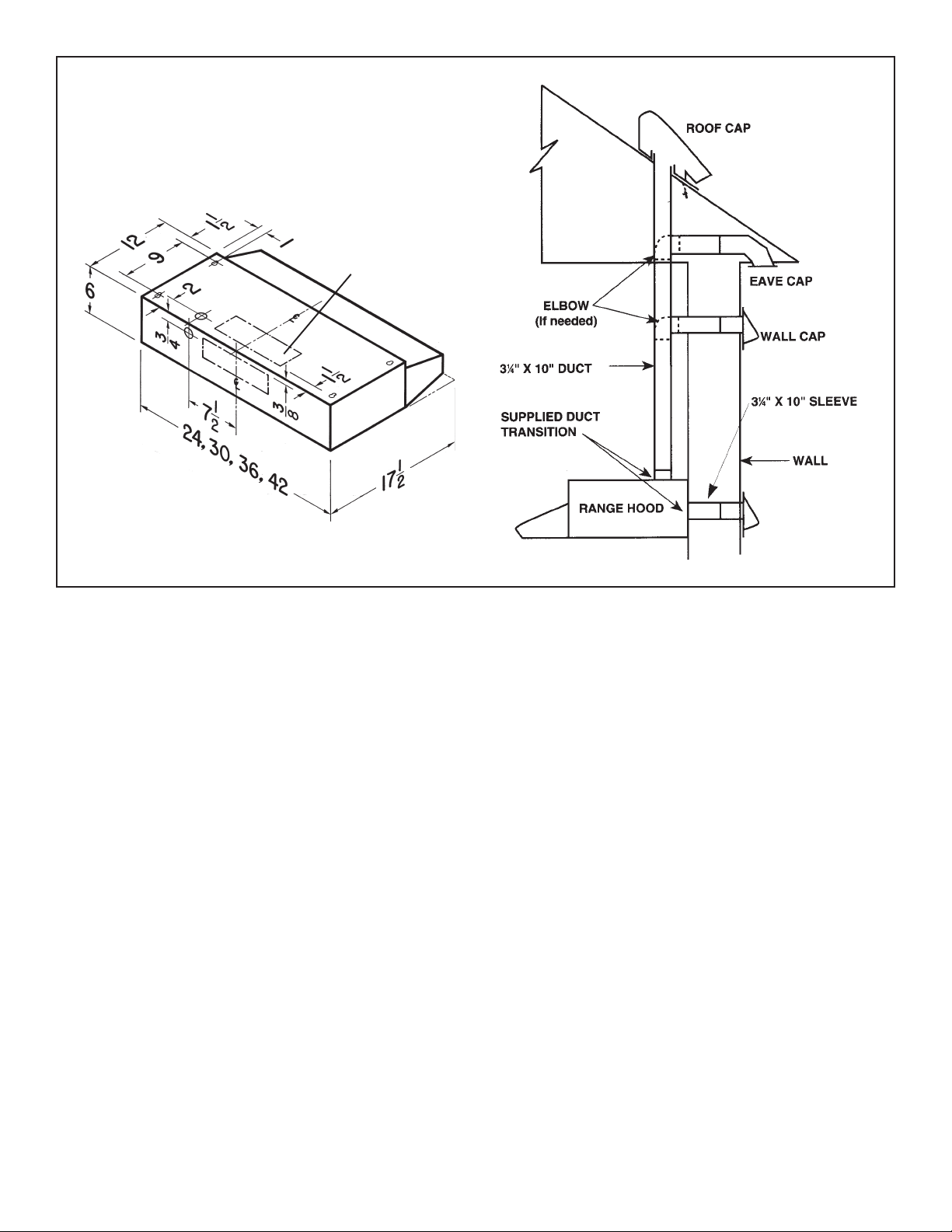
RL6100CK-H SERIES
VERTICAL OR HORIZONTAL
DISCHARGE
USING 3¼” X 10” DUCT
3¼” X 10”
FIGURE 1
2
Page 3
PREPARATION
1. Use the dimensional drawing to lay out the Range Hood’s mounting holes, wiring access and ductwork.
2. Make cutouts for wiring and ductwork.
3. If the hood is to be ducted, install the ductwork so that is flush to
the Range Hood’s mounting surface. (Refer to Figure 1)
4. Make sure that a grounded, 120VAC electrical receptacle is located within reach of the hood power cord. (Refer to “Electrical
Receptacle Location” on Page 1 for further information.)
5. Drill four 3/32” diameter pilot holes at points where mounting
holes are marked in the filler strips or cabinet bottom.
6. Insert four (4) mounting screws, leaving approximately ¼” of
thread exposed.
INSTALLATION
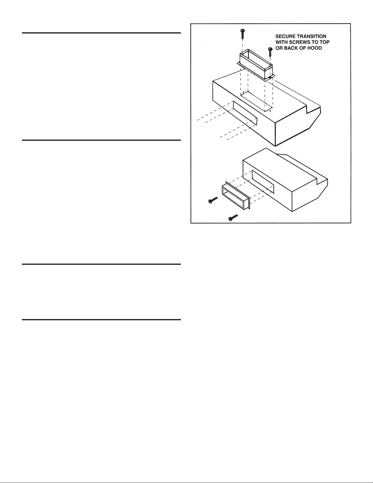
1. For RL6100 model, attach duct transition to top or back of hood
using screws provided. (Refer to Figure 2)
Note: for horizontal venting the damper in the duct transition may be removed to avoid interference with the wall cap.
2. Align hood’s keyhole mounting slots over the four partially installed screws.
3. Making sure the duct positions over the hood’s duct transition,
push the hood against the rear wall. Secure hood by tightening
screws.
4. Using a long blade screwdriver, reach into the discharge openings and be certain the damper operates freely.
5. Secure ducting to hood.
6. Install 75-watt (maximum) bulb in to receptacle.
(Purchase bulb locally).
7. Install filter and light lens.
FIGURE 2
REPLACEMENT PARTS
Should replacement parts be required, please indicate hood
model number and appropriate part number. Contact your NuTone
dealer or write to NuTone, 4820 Red Bank Road, Cincinnati, Ohio
45227-1599. Attn.: Parts Department.
OPERATION AND MAINTENANCE
NOTE: To avoid risk of fire, electrical shock, or injury, turn off
power at supply before servicing.
FILTERS
The aluminum filter should be removed once a week and washed
in hot detergent water. Rinse in clear, warm water and shake off
excess moisture before replacing. The filter may also be cleaned
in your dishwasher.
CLEANING
The hood should be wiped off occasionally both inside and out-
side using warm water, mild dish detergent and a soft cloth. Never
use scouring powders, steel wool pads or any other abrasive cleaners which will destroy the hood’s finish.
3
Page 4

REPLACEMENT FILTERS
PRODUCT
MODEL FILTER USE
Nutone Alternate 1 Alternate 2
RL6100CK-H K7589 BP29 97006931
RL6200CK-H K7588 41F 97007696
NUTONE ONE YEAR LIMITED WARRANTY
NuTone warrants to the original consumer purchaser of its products that such products will be free from defects in materials or
workmanship for a period of one year from the date of original purchase. THERE ARE NO OTHER WARRANTIES, EXPRESS OR
IMPLIED, INCLUDING, BUT NOT LIMITED TO, IMPLIED WARRANTIES OF MERCHANTABILITY OR FITNESS FOR A PARTICULAR PURPOSE.
During this one-year period, NuTone will, at its option, repair or replace, without charge, any product or part which is found to be
defective under normal use and service.
THIS WARRANTY DOES NOT EXTEND TO FLUORESCENT LAMP STARTERS AND TUBES. This warranty does not cover (a)
normal maintenance and service or (b) any products or parts which have been subject to misuse, negligence, accident, improper
maintenance or repair (other than by NuTone), faulty installation or installation contrary to recommended installation instructions.
The duration of any implied warranty is limited to the one-year period as specified for the express warranty. Some states do not
allow limitation on how long an implied warranty lasts, so the above limitation may not apply to you.
NUTONE’S OBLIGATION TO REPAIR OR REPLACE, AT NUTONE’S OPTION, SHALL BE THE PURCHASER’S SOLE AND
EXCLUSIVE REMEDY UNDER THIS WARRANTY. NUTONE SHALL NOT BE LIABLE FOR INCIDENTAL, CONSEQUENTIAL OR
SPECIAL DAMAGES ARISING OUT OF OR IN CONNECTION WITH PRODUCT USE OR PERFORMANCE. Some states do not
allow the exclusion or limitation of incidental or consequential damages, so the above limitation or exclusion may not apply to you.
This warranty gives you specific legal rights, and you may also have other rights, which vary from state to state. This warranty
supersedes all prior warranties.
To qualify for warranty service, you must (a) notify the company at the address or phone number below (b) give the model number
and part identification and (c) describe the nature of any defect in the product or part. At the time of requesting warranty service,
you must present evidence of the original purchase date.
NuTone, Inc., 4820 Red Bank Road, Cincinnati, OH 45227 (1-800-543-8687)
Product specifications subject to change without notice.
4
Printed in U.S.A., Rev. 8/02, Part No. 99043194B
Page 5

¡LEA Y CONSERVE ESTAS INSTRUCCIONES!
INSTRUCCIONES DE INSTALACIÓN
Campanas de estufa
Serie RL-H (RL6100CK-H, RL6200CK-H)
INSTRUCCIONES IMPORTANTES DE SEGURIDAD
ADVERTENCIA — PARA REDUCIR EL RIESGO DE INCENDIOS,
DESCARGAS ELÉCTRICAS O LESIONES PERSONALES
OBSERVE LAS SIGUIENTES PRECAUCIONES:
• Use esta unidad sólo de la manera indicada por el fabricante. Si tiene
preguntas, comuníquese con el fabricante.
• Antes de dar servicio o limpiar la unidad, interrumpa el suministro
eléctrico en el panel de servicio y bloquee el panel de servicio para
evitar que la electricidad se active accidentalmente.
Cuando no sea posible bloquear los medios de desconexión del servicio,
fije firmemente en un lugar prominente del panel de servicio un dispositivo
de advertencia, como por ejemplo una etiqueta.
PRECAUCIÓN: Para reducir el riesgo de incendio o de descargas
eléctricas, no use esta campana de estufa con un dispositivo adicional
de control de velocidad.
ADVERTENCIA — PARA REDUCIR EL RIESGO DE INCENDIO
PROVOCADO POR GRASA EN LA ESTUFA:
• Nunca deje las unidades de superficie desatendidas en ajustes altos
de calor. Los alimentos en ebullición provocan derrames grasosos y
con humo que se pueden inflamar. Caliente el aceite lentamente en
ajustes de calor bajo o medio.
• Siempre ENCIENDA la campana cuando cocine a calor alto o cuando
cocine alimentos inflamables.
• Limpie frecuentemente los ventiladores. No se debe permitir la
acumulación de grasa en el ventilador ni en el filtro.
• Use una cacerola del tamaño adecuado. Siempre use utensilios de
cocina apropiados para el tamaño del elemento de la superficie.
ADVERTENCIA — PARA REDUCIR EL RIESGO DE LESIONES
PERSONALES EN CASO DE QUE SE INCENDIE LA GRASA DE LA
ESTUFA, OBSERVE LAS SIGUIENTES PRECAUCIONES*:
• APAGUE LAS LLAMAS con una tapa de ajuste exacto, una charola
para galletas o una bandeja de metal y después apague el quemador.
TENGA CUIDADO PARA PREVENIR QUEMADURAS. Si las llamas
no se apagan inmediatamente, EVACÚE EL ÁREA Y LLAME A LOS
BOMBEROS.
• NUNCA LEVANTE UNA CACEROLA EN LLAMAS; podría quemarse.
• NO USE AGUA ni toallas húmedas, ya que provocará una violenta
explosión de vapor.
• Use un extintor SÓLO si:
1. Sabe que tiene un extintor clase ABC, y ya sabe cómo usarlo.
2. El incendio es pequeño y está confinado en el área en la que se inició.
3. Va a llamar a los Bomberos.
4. Puede combatir el incendio dando la espalda hacia una salida.
*Basado en “Kitchen Firesafety Tips” (Sugerencias para la seguridad
contra incendios en la cocina) publicado por NFPA.
INSTRUCCIONES PARA LA PUESTA A TIERRA
Este aparato debe estar conectado a tierra. En caso de un corto circuito
eléctrico, la puesta a tierra reduce el riesgo de una descarga eléctrica
al suministrar un cable de escape para la corriente eléctrica. Este
aparato está equipado con un cordón que tiene un cable con una
clavija a tierra. La clavija debe conectarse a una toma eléctrica que
esté instalada y conectada a tierra adecuadamente.
ADVERTENCIA - Una instalación inadecuada a tierra puede tener el
riesgo de una descarga eléctrica.
Consulte a un electricista calificado si no se entienden totalmente las
instrucciones de conexión a tierra, o si tiene alguna duda en cuanto a
la conexión a tierra apropiada del aparato.
No utilice una extensión eléctrica. Si el cordón de la fuente de
alimentación es demasiado corto, solicite a un electricista calificado
que instale una toma eléctrica cerca del aparato.
INSTRUCCIONES DE INSTALACIÓN
ADVERTENCIA — PARA REDUCIR EL RIESGO DE INCENDIOS,
DESCARGAS ELÉCTRICAS O LESIONES PERSONALES
OBSERVE LAS SIGUIENTES PRECAUCIONES:
• Una o más personas calificadas deben realizar el trabajo de
instalación y el cableado eléctrico, de acuerdo con todos los códigos
y normas correspondientes, inclusive los códigos y normas de
construcción específicos para incendios.
• Se necesita suficiente aire para que se lleve a cabo una combustión
adecuada y para la descarga de los gases a través del tubo de
humos (chimenea) del equipo quemador de combustible, para evitar
las contracorrientes. Siga las pautas y las normas de seguridad
del fabricante del equipo de calentamiento, como los publicados
por la Asociación Nacional de Protección contra Incendios (National
Fire Protection Association, NFPA), la Sociedad Americana de
Ingenieros en Calefacción, Refrigeración y Aire Acondicionado
(American Society for Heating, Refrigeration and Air Conditioning
Engineers, ASHRAE) y las autoridades de los códigos locales.
• Al cortar o perforar a través de la pared o del cielo raso, no dañe el
cableado eléctrico ni otros servicios ocultos.
• Los ventiladores con conductos siempre se deben conectar hacia
el exterior.
ADVERTENCIA: “Para reducir el riesgo de incendio, use solamente
conductos metálicos.”
PRECAUCIÓN: Para reducir el riesgo de incendio y para descargar
adecuadamente el aire, asegúrese de dirigir el aire hacia el exterior.
No descargue el aire en espacios contenidos entre paredes o cielos
rasos ni en áticos, sótanos bajos ni en la cochera.
PRECAUCIÓN: Sólo para uso en ventilación general. No se use para
descargar materiales ni vapores peligrosos o explosivos.
PLANEACIÓN
LUGAR DE LA INSTALACIÓN
• La altura recomendada de montaje es de 61 a 76 cm (24 a 30")
sobre la superficie para cocinar.
• La campana debe estar montada en la parte inferior de un gabinete
estándar de pared. Si la campana se debe montar directamente en la
pared, asegúrela en los montantes de la pared.
• Todo el cableado debe estar adecuadamente conectado a tierra.
Debe hacerse la conexión a un circuito de alumbrado de 110-120
VCA (15 Amp) en el interruptor automático de circuitos o en la caja
de fusibles.
UBICACIÓN DEL RECEPTÁCULO ELÉCTRICO
• Esta campana requiere que haya un receptáculo eléctrico de 120
VCA conectado a tierra cerca de ella.
(a) El receptáculo debe estar ubicado de manera que el cable de
alimentación de la campana se pueda conectar directamente en
el receptáculo. ¡No utilice una extensión eléctrica! Si el cordón
de alimentación de la campana es demasiado corto, solicite a un
electricista calificado que instale una toma eléctrica más cerca
de la campana.
El receptáculo debe ubicarse en un lugar donde el cordón de
(b)
alimentación de la campana no pueda entrar en contacto
con ninguna fuente de calor. Un lugar común es el interior
del gabinete, sobre la estufa.
SISTEMA DE CONDUCTOS
• La campana RL6100CK-H se instala con un conducto de 8.3 x 25.4
cm (3¼ x 10") con ventilación vertical u horizontal.
• Procure que la longitud de los conductos sea tan corta como es
posible. Trate de evitar el uso de codos en el sistema de conductos.
Todas las uniones deben estar adecuadamente selladas. No use
un conducto que sea menor que la descarga de la campana.
• No termine un conducto en el espacio de un ático. Tienda el sistema
de conductos hacia el exterior, usando una tapa de techo o de
5
pared para terminar el tramo.
Page 6

SERIE RL6100CK-H
DESCARGA VERTICAL U
HORIZONTAL USANDO UN
CONDUCTO DE 8.3 X 25.4 CM
(3¼ X 10")
3.8
30.4
22.9
15.2
1.9
19.1
61, 76.2, 91.4,106.7
1
8.3 X 25.4
3¼” X 10”
3.8
44.5
CODO
(Si se necesita)
CONDUCTO DE
8.3 X 25.4 CM
(3 ¼ X 10")
TRANSICIÓN
SUMINISTRADA
PARA EL
CONDUCTO
CAMPANA DE
TAPA DE TECHO
TAPA DE ALERO
TAPA DE PARED
MANGA DE 8.3 X 25.4
CM (3 ¼ X 10")
PARED
ESTUFA
FIGURA 1
6
Page 7

PREPARACIÓN
1. Use el esquema dimensional para disponer los orificios de montaje
de la campana de estufa, el acceso al cableado y el sistema de
conductos.
2. Haga los cortes para el cableado y el sistema de conductos.
3. Si la campana requiere conductos, instale el sistema de conductos
de manera que quede al ras de la superficie de montaje de la
campana de la estufa. (Consulte la figura 1)
4. Asegúrese de que haya un receptáculo eléctrico de 120 VCA
conectado a tierra al alcance del cable de alimentación de la
campana. (Consulte la sección “Ubicación del receptáculo
eléctrico” en la página 1 para obtener más información.)
5. Haga cuatro orificios piloto de .24 cm (3/32") de diámetro en los
puntos donde están marcados los orificios de montaje en las tiras
de relleno o la parte inferior del gabinete.
6. Inserte cuatro (4) tornillos de montaje, dejando aproximadamente
.64 cm (¼”) de rosca expuesta.
INSTALACIÓN
1. Para la campana modelo RL6100, conecte la transición del conducto
en la parte superior o posterior de la campana usando los tornillos
incluidos. (Consulte la figura 2)
Nota: para ventilación horizontal se puede quitar el regulador de
tiro en la transición del conducto para evitar la interferencia con
la tapa de pared.
2. Alinee las ranuras de montaje en forma de cerradura sobre los
cuatro tornillos parcialmente instalados.
3. Asegurándose de la posición del conducto sobre la transición del
conducto de la campana, empuje la campana contra la pared
posterior. Fije la campana apretando los tornillos.
4. Con un desarmador largo acceda a las aberturas de la descarga y
asegúrese de que el regulador de tiro funcione libremente.
5. Fije el sistema de conductos a la campana.
6. Instale un foco de 75-watts (como máximo) en el receptáculo.
(Compre el foco en una tienda de su localidad).
7. Instale el filtro y los lentes de la lámpara.
FIJE LA TRANSICIÓN
CON TORNILLOS A
LA PARTE SUPERIOR
O POSTERIOR DE LA
CAMPANA.
FIGURA 2
PIEZAS DE REPUESTO
Si se requieren piezas de repuesto, indique el número de modelo de
la campana y el número de pieza correspondiente. Comuníquese con
su concesionario NuTone o escriba a NuTone, 4820 Red Bank Road,
Cincinnati, Ohio 45227-1599. Attn.: Parts Department.
OPERACIÓN Y MANTENIMIENTO
NOTA: Para evitar el riesgo de incendio, descargas eléctricas o
lesiones, interrumpa la energía en el suministro antes de dar servicio
a la unidad.
FILTROS
Una vez a la semana debe quitar el filtro de aluminio y lavarlo en
agua caliente con detergente. Enjuague con agua tibia limpia y elimine
el exceso de humedad antes de volver a colocarlo. También puede
limpiar el filtro en el lavaplatos.
LIMPIEZA
Debe limpiar ocasionalmente tanto el interior como el exterior de la
campana con agua tibia, detergente suave para platos y un paño
suave. Nunca use polvos abrasivos, fibras de lana de acero ni ningún
otro limpiador abrasivo que pueda destruir el acabado de la campana.
7
Page 8

FILTROS DE REEMPLAZO
MODELO DEL
PRODUCTO USE EL FILTRO
Nutone Alternativa 1 Alternativa 2
RL6100CK-H K7589 BP29 97006931
RL6200CK-H K7588 41F 97007696
GARANTIA NUTONE LIMITADA POR UN AÑO
NuTone garantiza al consumidor comprador original de sus productos que dichos productos carecerán de defectos en materiales
o en mano de obra por un período de un año a partir de la fecha original de compra. NO EXISTEN OTRAS GARANTIAS, EXPLICITAS
O IMPLICITAS, INCLUYENDO, PERO NO LIMITADAS A, GARANTIAS IMPLICITAS DE COMERCIALIZACION O APTITUD PARA
UN PROPOSITO PARTICULAR.
Durante el período de un año, y a su propio criterio, NuTone reparará o reemplazará, sin costo alguno cualquier producto o pieza
que se encuentre defectuosa bajo condiciones normales de servicio y uso.
ESTA GARANTIA NO SE APLICA A TUBOS Y ARRANCADORES DE LAMPARAS FLUORESCENTES. Esta garantía no cubre (a)
mantenimiento y servicio normales o (b) cualquier producto o piezas que hayan sido utilizadas de forma errónea, negligente, que
hayan causado un accidente, o que hayan sido reparadas o mantenidas inapropiadamente (por otras compañías que no sean
NuTone), instalación defectuosa, o instalación contraria a las instrucciones de instalación recomendadas.
La duración de cualquier garantía implícita se limita a un período de un año como se especifica en la garantía expresa. Algunos
estados no permiten limitaciones en cuanto al tiempo de expiración de una garantía implícita, por lo que la limitación antes
mencionada puede no aplicarse a usted.
LA OBLIGACION DE NUTONE DE REPARAR O REEMPLAZAR, SIGUIENDO EL CRITERIO DE NUTONE, DEBERA SER EL
UNICO Y EXCLUSIVO RECURSO LEGAL DEL COMPRADOR BAJO ESTA GARANTIA. NUTONE NO SERA RESPONSABLE
POR DAÑOS INCIDENTALES, CONSIGUIENTES, O POR DAÑOS ESPECIALES QUE SURJAN A RAIZ DEL USO O DESEMPEÑO
DEL PRODUCTO.
Algunos estados no permiten la exclusión o limitación de daños incidentales o consiguientes, por lo que la limitación antes
mencionada puede no aplicarse a usted. Esta garantía le proporciona derechos legales específicos, y usted puede también tener
otros derechos, los cuales varían de estado a estado. Esta garantía reemplaza todas las garantías anteriores.
Para calificar en la garantía de servicio, usted debe (a) notificar a la compañía al domicilio o al teléfono que se menciona abajo (b)
dar el número del modelo y la identificación de la pieza, y (c) describir la naturaleza de cualquier defecto en el producto o pieza.
En el momento de solicitar servicio cubierto por la garantía, usted debe de presentar evidencia de la fecha original de compra.
NuTone, Inc., 4820 Red Bank Road, Cincinnati, OH 45227 (1-800-543-8687)
Las especificaciones del producto están sujetas a cambio sin previo aviso.
8
Impreso en los EE.UU., Rev. 8/02, No de parte 99043194B
 Loading...