

Page 1
RADIATION DAMPER
ACCESSORY KIT
READ AND SAVE THESE INSTRUCTIONS
For Use in 1, 2 or 3 Hour Rated Floor-Ceiling and Roof-Ceiling Designs.
Horizontal Mount Only.
For use with the following ventilation fan models:
• Broan DX90, DX110, HD50, HD80, 676, 676EX, 683, 683C, 684, 770, 784
• NuTone HD50NT, HD80NT, NT080C, 50NT, 80NT, 671SP, 672SP, 684NT
The following components are included with this accessory
kit:
(1) Radiation Damper Assembly
(1) Metal Duct Connector
(1) Metal Fan Grille
(2) Slide Channels
(4) Support Angles
(1) Plaster Guard
Parts Bag Containing:
(8) #8-18 x 0.375” Screws
(2) #8-18 x 0.812” Screws
Identify the following ventilation fan (purchased
separately) components and discard:
• Plastic Fan Grille Assembly
• Plastic Duct Connector Assembly
METAL DUCT
CONNECTOR
HOUSING
MODEL RDJ1
Page 1
SUPPORT
ANGLE
SLIDE
CHANNEL
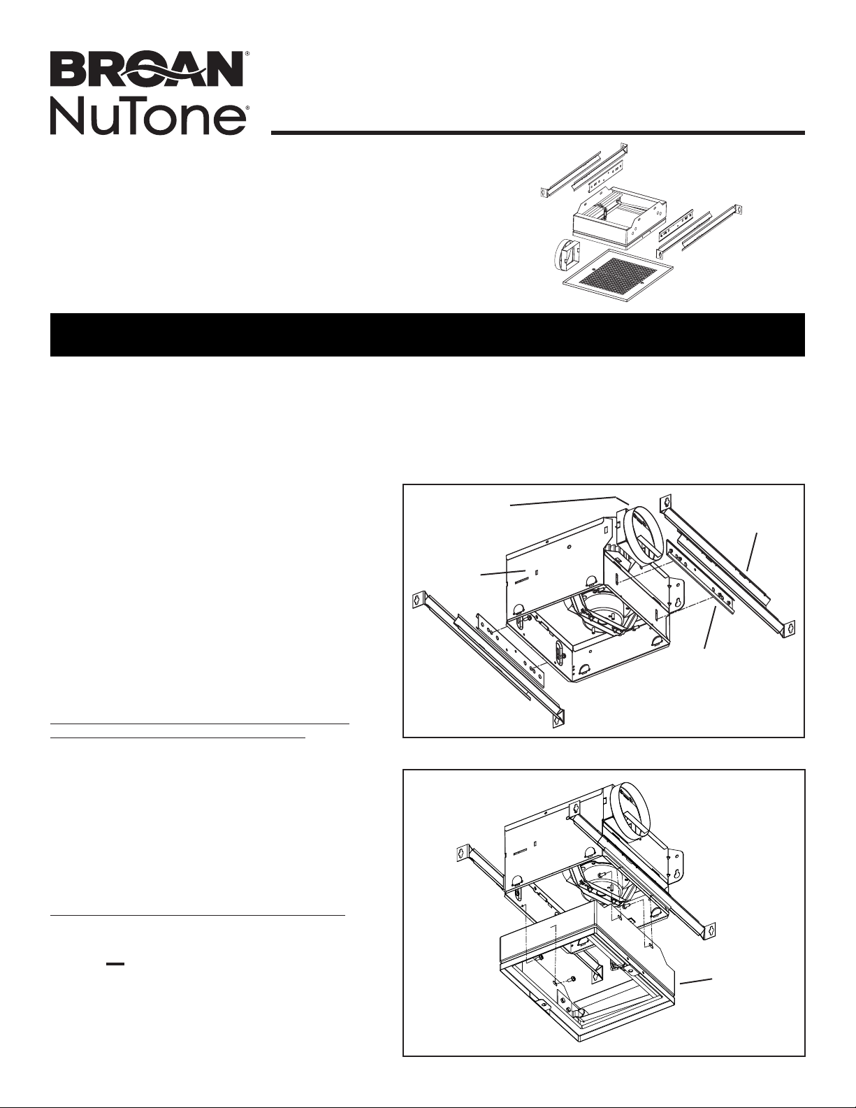
Assemble slide channels, support angles and duct
connector to ventilation fan housing: (Fig. 1)
1. Snap metal duct connector onto housing. Make
sure that tabs on the duct connector lock into the
slots on the housing. Damper flap hinge should be
positioned toward top of housing.
2. Attach the (2) slide channels to the housing using
(4) #8-18 x 0.375” sheet metal screws (provided).
The slide channel position can be adjusted to
accommodate different ceiling material thicknesses.
3. Insert (2) support angles into each slide channel.
Assemble radiation damper to fan housing: (Fig. 2)
4. Position radiation damper on the inlet side of the
fan so the arrow shown on spec label in the damper
points UP in the finished installation. Attach the
damper to the fan using (4) #8-18 x 0.375” sheet
metal screws (provided). There must be a minimum
of two connections on each of two opposite sides.
Take care to ensure that the fasteners do not
interfere with the closing of the damper curtain.
FIG. 1
RADIATION
DAMPER
ASSEMBLY
FIG. 2
Page 2
MODEL RDJ1
Page 2
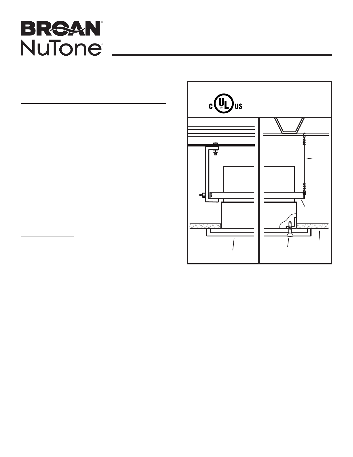
CULUS INSTALLATION
INSTRUCTIONS
5. Plan installation so that ceiling penetration is located
within ceiling tiles or panels without necessitating cuts
in any ceiling suspension main runners or cross tees.
Ifrequired, a maximum of one runner or cross tee
may be cut to accommodate desired damper location.
Cutends must be supported by a minimum 12 gauge
(3mm) steel, vertical hanger wire.
6. Mount fan/damper assembly to the deck or ceiling
structure above or adjacent to the assembly. If the
assembly is hung from the structure above, a minimum
12 gauge (3mm) steel, hanger wire must be used. There
must be a minimum of two wires on each of two opposite
sides. If the assembly is directly mounted to the adjacent
structure, use #8 (M4) sheet metal screws or 1/4”
(6mm) diameter bolts with nuts (hardware not provided)
to mechanically fasten it to the structure. Position fan/
damper assembly so that the inlet face of the radiation
damper is flush with the finished surface of the ceiling.
Ceiling opening must be no larger than the inlet opening
of the damper.
7. New Construction
A housing mask has been provided to keep construction
dust, drywall spray, paint, etc. from damaging the
radiation damper or blower assembly.
a) Bend up the small tab of the mask.
b) Tuck the opposite side of the mask under one of the
damper’s grille mounting ears and push mask up into
damper housing.
Remove mask before installing grille or operating fan.
8. Attach the metal grille over the inlet face of the radiation
damper using (2) #8-18 x 0.812” sheet metal screws
(provided).
CLASSIFIED
GRILLE
FAN
SEE DETAILS ON UL
CLASSIFICATION
MARKING ON
PRODUCT
DAMPER
GRILLE
SCREW
MOUNTING
BRACKET
WIRE
CEILING
Page 3
MODEL RDJ1
Page 3
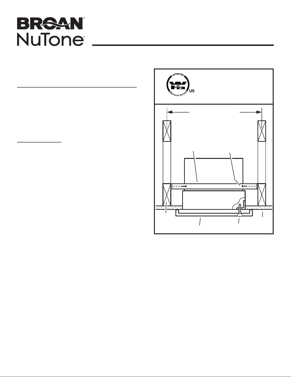
WARNOCK HERSEY
INSTALLATION INSTRUCTIONS
5. Position fan/damper assembly so that the inlet face of
the radiation damper is flush with the finished surface of
the ceiling. Fasten fan/damper assembly to the building
structure by driving #10 (M5) minimum sheet metal
screws or #8d minimum nails (hardware not provided)
through the fan mounting brackets and into the ceiling
joists. There must be a minimum of two fasteners on
each of two opposite sides. Ceiling opening must be no
larger than the inlet opening of the damper.
6. New Construction
A housing mask has been provided to keep construction
dust, drywall spray, paint, etc. from damaging the
radiation damper or blower assembly.
a) Bend up the small tab of the mask.
b) Tuck the opposite side of the mask under one of the
damper’s grille mounting ears and push mask up into
damper housing.
Remove mask before installing grille or operating fan.
Attach the metal grille over the inlet face of the radiation
damper using (2) #8-18 x 0.812” sheet metal screws
(provided).
WARNOCK HERSEY LISTED
16” OR 24” ON CENTER
MOUNTING
BRACKET
WARNOCK HERSEY LISTING
INCLUDES DAMPER ONLY. IT
DOES NOT INCLUDE EXHAUST
FAN. DAMPERS MAY BE USED
WITH UL LISTED FAN MODELS
NOTED.
FASTENER
FAN
DAMPER
WOOD
FRAMING
MEMBER
OR JOIST
GRILLE
CEILING
GRILLE SCREW
Page 4
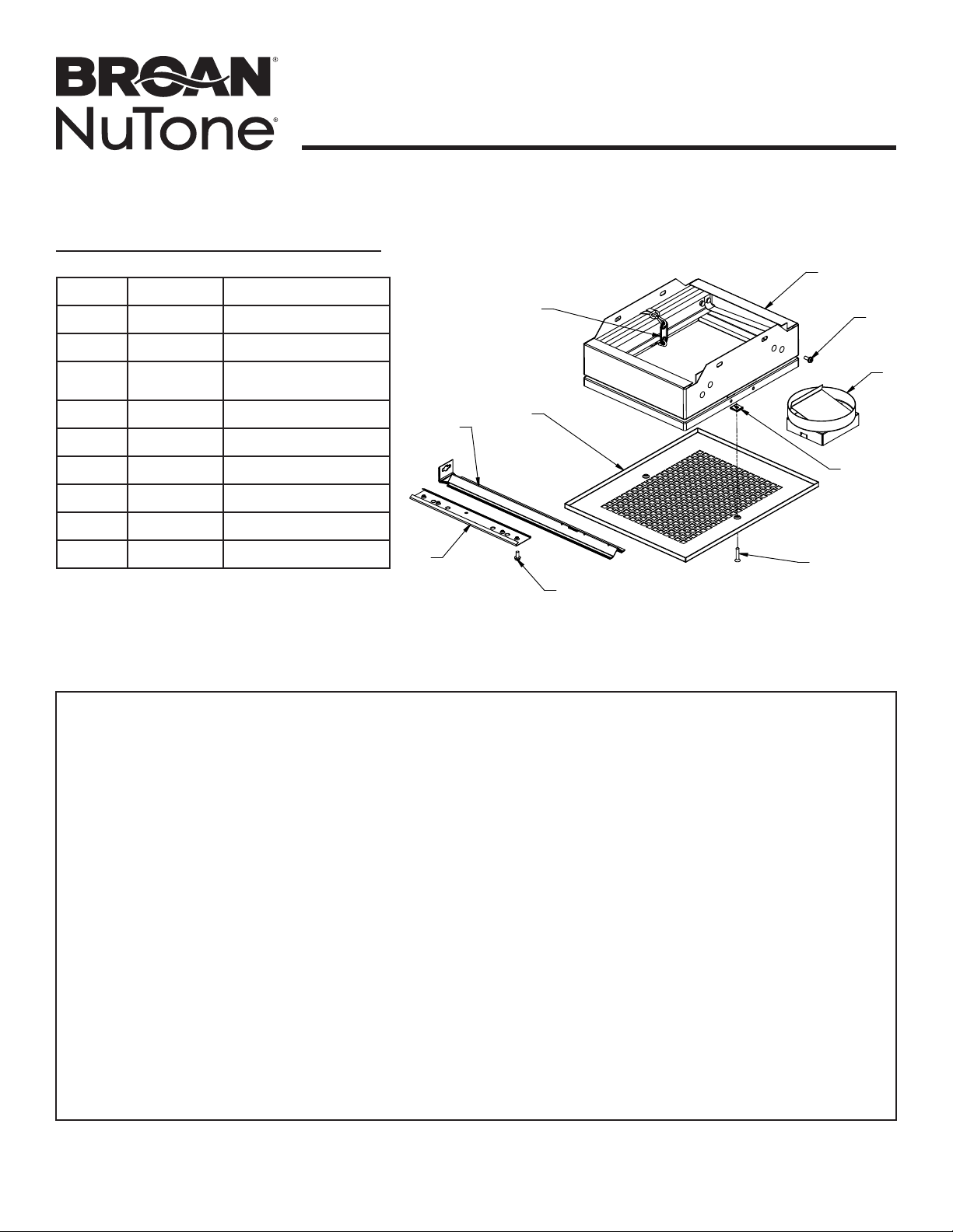
SERVICE PARTS
Key No. Part No. Description
1 99523579 Fusible Link
2 99260485 Sheet Metal Nut
3 99170245
4 99150573 Grille Screw
5 99523357 Radiation Damper
6 98009908 Metal Grille
7 97015727 Metal Duct Connector
8 98007763 Slide Channel
Damper / Slide Channel
Screw
MODEL RDJ1
Page 4
5
1
6
9
3
7
2
9 98003036 Support Angle
8
4
3
BROAN-NUTONE ONE YEAR LIMITED WARRANTY
Broan-NuTone warrants to the original consumer purchaser of its products that such products will be free from defects in materials or workmanship for
a period of one year from the date of original purchase. THERE ARE NO OTHER WARRANTIES, EXPRESS OR IMPLIED, INCLUDING, BUT NOT
LIMITED TO, IMPLIED WARRANTIES OF MERCHANTABILITY OR FITNESS FOR A PARTICULAR PURPOSE.
During this one-year period, Broan-NuTone will, at its option, repair or replace, without charge, any product or part which is found to be defective under
normal use and service.
THIS WARRANTY DOES NOT EXTEND TO FLUORESCENT LAMP STARTERS, TUBES, HALOGEN AND INCANDESCENT BULBS, FUSES,
FILTERS, DUCTS, ROOF CAPS, WALL CAPS AND OTHER ACCESSORIES FOR DUCTING. This warranty does not cover (a) normal maintenance
and service or (b) any products or parts which have been subject to misuse, negligence, accident, improper maintenance or repair (other than by
Broan-NuTone), faulty installation or installation contrary to recommended installation instructions.
The duration of any implied warranty is limited to the one-year period as specified for the express warranty. Some states do not allow limitation on how
long an implied warranty lasts, so the above limitation may not apply to you.
BROAN-NUTONE’S OBLIGATION TO REPAIR OR REPLACE, AT BROAN-NUTONE’S OPTION, SHALL BE THE PURCHASER’S SOLE AND
EXCLUSIVE REMEDY UNDER THIS WARRANTY. BROAN-NUTONE SHALL NOT BE LIABLE FOR INCIDENTAL, CONSEQUENTIAL OR SPECIAL
DAMAGES ARISING OUT OF OR IN CONNECTION WITH PRODUCT USE OR PERFORMANCE. Some states do not allow the exclusion or limitation
of incidental or consequential damages, so the above limitation or exclusion may not apply to you.
This warranty gives you specific legal rights, and you may also have other rights, which vary from state to state. This warranty supersedes all prior
warranties.
To qualify for warranty service, you must (a) notify Broan-NuTone at the address or telephone number below, (b) give the model number and part
identification and (c) describe the nature of any defect in the product or part. At the time of requesting warranty service, you must present evidence of
the original purchase date.
Broan-NuTone LLC, 926 W. State Street, Hartford, Wisconsin 53027 www.broan.com www.nutone.com 800-558-1711
Broan-NuTone Canada, Inc., 1140 Tristar Drive, Mississauga, Ontario L5T 1H9 www.broan.ca www.nutone.ca 877-896-1119
99044707A
Page 5

MODÈLE RDJ1
ENSEMBLE DE CLAPET
ANTI-RAYONNEMENT
LIRE CES DIRECTIVES ET LES CONSERVER
À utiliser dans les planchers/plafonds et toits/plafonds classés résistants au feu 1, 2 ou 3 heures.
Montage horizontal seulement.
À utiliser avec les modèles de ventilateurs d’aération suivants :
• Broan DX90, DX110, HD50, HD80, 676, 676EX, 683, 683C, 684, 770, 784
• NuTone HD50NT, HD80NT, NT080C, 50NT, 80NT, 671SP, 672SP, 684NT
Page 5
Cet ensemble comprend les pièces suivantes :
(1) Ensemble de clapet anti-rayonnement
(1) Raccord de conduit métallique
(1) Grille de ventilateur en métal
(2) Coulisses
(4) Supports angulaires
(1) Protecteur anti-plâtre
Sachet de pièces contenant :
(8) Vis n° 8-18 x 0,375 po
(2) Vis n° 8-18 x 0,812 po
Repérez et jetez les pièces de ventilateur suivantes
(achetées séparément) :
• Ensemble de grille en plastique
• Ensemble de raccord de conduit en plastique
Assemblez les coulisses, les supports angulaires et le
raccord de conduit sur le boîtier du ventilateur : (Fig. 1)
1. Enclenchez le raccord de conduit métallique sur le
boîtier. Assurez-vous que les ergots du raccord de
conduit s’insèrent dans les fentes du boîtier. Le pivot
du clapet doit être tourné vers le haut duboîtier.
2. Fixez les (2) coulisses à l’aide de (4) vis à tôle
n° 8-18 x 0,375 po (fournies). La position des
coulisses peut être réglée pour convenir à différentes
épaisseurs de matériau de plafond.
3. Insérez (2) supports angulaires dans chaque
coulisse.
Assemblez le clapet anti-rayonnement sur le boîtier
duventilateur : (Fig. 2)
4. Positionnez le clapet anti-rayonnement à l’entrée
du ventilateur de sorte que la flèche figurant sur
l’autocollant soit pointée vers le HAUT, une fois
l’installation terminée. Fixez le clapet au ventilateur à
l’aide de (4) vis à tôle n° 8-18 x 0,375po (fournies).
Une paire de côtés opposés doit comporter
au moins deux points d’ancrage sur chacun.
Assurez-vous que les fixations ne nuiront pas à la
fermeture du rideau du clapet.
RACCORD
DE CONDUIT
MÉTALLIQUE
BOÎTIER
SUPPORT
ANGULAIRE
COULISSE
FIG. 1
ENSEMBLE DE
CLAPET ANTI-
RAYONNEMENT
FIG. 2
Page 6

MODÈLE RDJ1
Page 6
DIRECTIVES
D’INSTALLATION CULUS
5. Prévoyez l’installation de manière à ce que le point
d’entrée soit situé dans un carreau ou un panneau
du plafond sans avoir à couper aucun élément de la
structure de suspension. Si nécessaire, ne coupez
pas plus d’un seul profilé ou d’une seule jonction pour
permettre l’installation à l’endroit voulu. Les extrémités
coupées doivent être supportées par un fil d’acier à
suspension de calibre 12 au minimum (3 mm).
6. Fixez l’assemblage du ventilateur et du clapet à la
charpente de l’étage ou du plafond par le haut ou par
les côtés. Si l’assemblage est suspendu, utilisez du fil
d’acier à suspension de calibre 12 au minimum (3 mm).
Une paire de côtés opposés doit comporter au moins
deux points d’ancrage sur chacun. Si l’assemblage est
fixé directement à la structure adjacente, utilisez des
vis à tôle n° 8 (M4), ou des boulons et des écrous de
1/4po (6 mm) de diamètre afin de fixer les supports à
lacharpente. Positionnez l’assemblage ventilateur/clapet
de sorte que l’entrée du clapet anti-rayonnement affleure
la surface finie du plafond. L’ouverture pratiquée dans le
plafond ne doit pas être plus grande que la prise d’entrée
du clapet.
7. Construction neuve
Un masque de boîtier est fourni afin de protéger le clapet
anti-rayonnement et le ventilateur de la poussière de
construction, du plâtre, de la peinture, etc.
a) Repliez vers le haut la petite languette du masque.
b) Coincez l’autre extrémité du masque sous l’une des
oreilles de montage de la grille du clapet et remontez
lemasque dans le boîtier du clapet.
Retirez ce masque avant d’installer la grille ou de faire
fonctionner le ventilateur.
8. Fixez la grille métallique sur l’entrée du clapet à l’aide de
(2) vis à tôle n° 8-18 x 0,812 po (fournies).
HOMOLOGUÉ
VENTILATEUR
GRILLE
VOIR LES DÉTAILS
DE L’HOMOLOGATION
UL SUR L’ÉTIQUETTE
DUPRODUIT
CLAPET
VIS DE
GRILLE
SUPPORT
DEMONTAGE
PLAFOND
FIL
Page 7

MODÈLE RDJ1
Page 7
DIRECTIVES D’INSTALLATION
WARNOCK HERSEY
5. Positionnez l’assemblage ventilateur/clapet de sorte que
l’entrée du clapet anti-rayonnement affleure la surface
finie du plafond. Fixez le ventilateur/clapet à la charpente
de l’édifice à l’aide de vis à tôle n° 10 (M5) au minimum
ou de clous n° 8d au minimum (non fournis) au travers
des supports de montage dans les solives du plafond.
Chaque paire de côtés opposés doit comporter au moins
deux points d’ancrage sur chacun. L’ouverture pratiquée
dans le plafond ne doit pas être plus grande que la prise
d’entrée du clapet.
6. Construction neuve
Un masque de boîtier est fourni afin de protéger le clapet
anti-rayonnement et le ventilateur de la poussière de
construction, du plâtre, de la peinture, etc.
a) Repliez vers le haut la petite languette du masque.
b) Coincez l’autre extrémité du masque sous l’une des
oreilles de montage de la grille du clapet et remontez
lemasque dans le boîtier du clapet.
Retirez ce masque avant d’installer la grille ou de faire
fonctionner le ventilateur.
Fixez la grille métallique sur l’entrée du clapet à l’aide
de(2) vis à tôle n° 8-18 x 0,812 po (fournies).
HOMOLOGATION WARNOCK
HERSEY
(16 PO OU 24 PO) AU CENTRE
SUPPORT DE
MONTAGE
L’HOMOLOGATION WARNOCK
HERSEY NE COMPREND QUE
LE CLAPET. ELLE N’INCLUT PAS
LEVENTILATEUR D’ÉVACUATION.
LECLAPET PEUT ÊTRE UTILISÉ
AVEC LES MODÈLES DE
VENTILATEURS HOMOLOGUÉS UL.
40,6 OU 61 CM
CLOU OU VIS
VENTILATEUR
CLAPET
CHARPENTE
OU SOLIVE
GRILLE
PLAFOND
VIS DE GRILLE
Page 8

PIÈCES DE RECHANGE
Repère N° de pièce Description
1 99523579 Lien fusible
2 99260485 Écrou à tôle
3 99170245
4 99150573 Vis de grille
5 99523357
6 98009908 Grille métallique
7 97015727
8 98007763 Coulisse
9 98003036 Support angulaire
Vis pour clapet /
coulisse
Clapet
anti-rayonnement
Raccord de conduit
métallique
MODÈLE RDJ1
Page 8
5
1
6
9
8
4
3
3
7
2
GARANTIE LIMITÉE D’UN AN BROAN-NUTONE
Broan-NuTone garantit à l’acheteur original que les produits vendus en vertu de la présente sont libres de tout vice de matériau ou de fabrication pour une
période d’un an à compter de la date d’achat originale. CETTE GARANTIE NE COMPORTE AUCUNE AUTRE GARANTIE, EXPRESSE OU TACITE,
Y COMPRIS, MAIS SANS S’Y LIMITER, LES GARANTIES TACITES DE VALEUR MARCHANDE OU D’ADAPTATION À UN USAGE PARTICULIER.
Durant cette période d’un an, Broan-NuTone réparera ou remplacera gratuitement, à sa discrétion, tout produit ou toute pièce jugés défectueux dans
des conditions normales d’utilisation.
CETTE GARANTIE NE S’APPLIQUE PAS AUX TUBES FLUORESCENTS ET AUX DÉMARREURS, NI AUX AMPOULES HALOGÈNES OU
INCANDESCENTES, FUSIBLES, FILTRES, CONDUITS, CAPUCHONS DE TOIT, CAPUCHONS MURAUX ET AUTRES ACCESSOIRES POUR
CONDUITS. Cette garantie ne couvre pas (a) les frais d’entretien ou de service normaux ni (b) tout produit ou toute pièce soumis à un abus, une
négligence, un accident, un entretien ou une réparation inadéquats (autres que ceux effectués par Broan-NuTone), une mauvaise installation ou une
installation contraire aux instructions recommandées.
La durée de toute garantie tacite est limitée à la période d’un an stipulée pour la garantie expresse. Certains territoires ou provinces interdisant de limiter
la durée d’une garantie tacite, la limitation ci-dessus peut ne pas s’appliquer à votre situation.
L’OBLIGATION POUR BROAN-NUTONE DE RÉPARER OU DE REMPLACER LE PRODUIT, À SA DISCRÉTION, CONSTITUE LE SEUL RECOURS
DE L’ACHETEUR EN VERTU DE LA PRÉSENTE GARANTIE. BROAN-NUTONE NE PEUT ÊTRE TENUE RESPONSABLE DES DOMMAGES
INDIRECTS OU CONSÉCUTIFS NI DES DOMMAGES-INTÉRÊTS PARTICULIERS DÉCOULANT DE L’UTILISATION OU DU RENDEMENT DU
PRODUIT. Certains territoires ou provinces ne permettant pas la limitation ou l’exclusion des dommages indirects ou consécutifs, la limitation ci-dessus
peut ne pas s’appliquer à votre situation.
La présente garantie vous confère des droits spécifiques reconnus par la loi. D’autres droits pourraient également vous être accordés selon la législation
locale en vigueur. La présente garantie remplace toutes les autres garanties précédentes.
Pour vous prévaloir de cette garantie, vous devez (a) aviser Broan-NuTone à l’adresse ou au numéro de téléphone indiqués ci-dessous, (b) donner le
numéro de modèle du produit et le numéro d’identification de la pièce et (c) décrire la nature de la défectuosité du produit ou de la pièce. Lors de votre
demande de garantie, vous devez présenter une preuve de la date d’achat originale.
Broan-NuTone LLC, 926 W. State Street, Hartford, Wisconsin 53027 www.broan.com www.nutone.com 800-558-1711
Broan-NuTone Canada, Inc., 1140 Tristar Drive, Mississauga, Ontario L5T 1H9 www.broan.ca www.nutone.ca 877-896-1119
99044707A
Page 9

MODELO RDJ1
JUEGO DE ACCESORIOS
PARA REGULADOR
DERADIACIÓN
LEA Y CONSERVE ESTAS INSTRUCCIONES
Para usarse en los diseños de piso a cielo raso y techo a cielo raso con clasificación de 1, 2 o 3 horas.
Montaje horizontal solamente.
Para usarse con los siguientes modelos de ventilador:
• Broan DX90, DX110, HD50, HD80, 676, 676EX, 683, 683C, 684, 770, 784
• NuTone HD50NT, HD80NT, NT080C, 50NT, 80NT, 671SP, 672SP, 684NT
Con este juego de accesorios se incluyen los siguientes
componentes:
(1) Conjunto del regulador de radiación
(1) Conector para conductos metálicos
(1) Rejilla para ventilador de metal
(2) Ranuras de deslizamiento
(4) Ángulos de soporte
(1) Protección para yeso
Bolsa de piezas que contiene:
(8) Tornillos #8-18 x 0.375 pulg.
(2) Tornillos #8-18 x 0.812 pulg.
Identifique los siguientes componentes del ventilador
(secompran por separado) y deseche:
• Conjunto de la rejilla del ventilador de plástico
• Conjunto del conector del conducto de plástico
Arme las ranuras de deslizamiento, los ángulos de soporte
y el conector de conductos a la cubierta delventilador:
(Fig. 1)
1. Conecte a presión el conector del conducto metálico a la
cubierta. Asegúrese de que las lengüetas del conector
de conductos queden fijas en las ranuras de la cubierta.
La bisagra de la aleta del regulador debeestar colocada
apuntando hacia la parte superior de la cubierta.
2. Fije las (2) ranuras de deslizamiento a la cubierta
utilizando (4) tornillos de chapa metálica
#8-18 x 0.375 pulg. (incluidos). La posición de la ranura
de deslizamiento se puede ajustar para adecuarse a
espesores diferentes del material del cielo raso.
3. Inserte (2) ángulos de soporte en cada ranura de
deslizamiento.
Arme el regulador de radiación a la cubierta delventilador:
(Fig. 2)
4. Coloque el regulador de radiación en el lado de entrada
del ventilador, de modo que la flecha que aparece en la
etiqueta de especificaciones del regulador apunte hacia
ARRIBA en la instalación terminada. Fije el regulador al
ventilador con los (4) tornillos de chapa metálica
#8-18 x 0.375pulg. (incluidos). Debe haber un mínimo de
dos conexiones en cada uno de los dos lados opuestos.
Tenga cuidado de asegurarse de que los sujetadores
nointerfieran con el cierre de la cortina del regulador.
CONECTOR PARA
CONDUCTO
METÁLICO
CUBIERTA
RANURA DE
DESLIZAMIENTO
Página 9
ÁNGULO DE
SOPORTE
FIG. 1
CONJUNTO DEL
REGULADOR
DE RADIACIÓN
FIG. 2
Page 10

MODELO RDJ1
Página 10
INSTRUCCIONES DE
INSTALACIÓN SEGÚN CULUS
5. Planee la instalación de tal modo que la abertura en el
cielo raso quede ubicada entre los azulejos o paneles
del cielo raso sin necesidad de hacer cortes en
T transversales ni en vigas principales de suspensión.
Si se requiere, puede cortarse un máximo de una
T o una viga para colocar el regulador en la posición
deseada. Los extremos cortados deben soportarse con
un alambre de suspensión vertical, de acero de calibre
12 (3 mm) como mínimo.
6. Monte el conjunto de ventilador/regulador en la
plataforma o estructura del cielo raso que se encuentra
arriba o adyacente al conjunto. Si el conjunto cuelga
de la estructura superior, debe usar un alambre de
suspensión de acero con un calibre 12 (3 mm) como
mínimo. Debe haber un mínimo de dos alambres en
cada uno de los dos lados opuestos. Si el conjunto se
monta directamente a la estructura adyacente, use
tornillos de chapa metálica #8 (M4) o pernos de
1/4pulg. (6 mm) de diámetro con tuercas (no se
incluyen los herrajes) para sujetarlo mecánicamente a la
estructura. Coloque el conjunto de ventilador y regulador
de tal modo que la cara de entrada del regulador de
radiación quede al ras con la superficie terminada del
cielo raso. La abertura del cielo raso no debe ser más
grande que la abertura de entrada del regulador.
7. Nueva construcción
Se incluye una cubierta protectora para impedir la caída
de polvos de construcción, rocíos de yeso, pintura, etc.
en el regulador de radiación o conjunto del ventilador,
loscuales podrían dañarlo.
a) Doble hacia arriba la aleta pequeña de la cubierta
protectora.
b) Meta el lado opuesto de la cubierta protectora debajo
de una de las orejetas de montaje de la rejilla del
regulador. Empuje la cubierta protectora hacia dentro
dela caja del regulador.
Quite la cubierta protectora antes de instalar la rejilla o
de poner a funcionar el ventilador.
8. Fije la rejilla metálica sobre la cara de entrada del
regulador de radiación con (2) tornillos de chapa
metálica #8-18 x 0.812 pulg. (incluidos).
CLASIFICADO
VENTILADOR
REJILLA
VEA LOS DETALLES
EN LA MARCA
DECLASIFICACIÓN UL
DEL PRODUCTO
ALAMBRE
REGULADOR
TORNILLO
DELA REJILLA
SOPORTE
DE MONTAJE
CIELO RASO
Page 11

MODELO RDJ1
Página 11
INSTRUCCIONES DE
INSTALACIÓN SEGÚN
WARNOCK HERSEY
5. Coloque el conjunto de ventilador y regulador de tal
modo que la cara de entrada del regulador de radiación
quede al ras con la superficie terminada del cielo raso.
Sujete el conjunto de ventilador/regulador a la estructura
del edificio fijando tornillos de chapa metálica de tamaño
mínimo #10 (M5) o clavos de un tamaño mínimo #8d
(no se incluyen los herrajes) a través de los soportes
demontaje del ventilador y hacia las vigas del cielo raso.
Debe haber un mínimo de dos sujetadores en cada uno
de los dos lados opuestos. La abertura del cielo raso
no debe ser más grande que la abertura de entrada
delregulador.
6. Nueva construcción
Se incluye una cubierta protectora para impedir la caída
de polvos de construcción, rocíos de yeso, pintura, etc.
en el regulador de radiación o conjunto del ventilador,
loscuales podrían dañarlo.
a) Doble hacia arriba la aleta pequeña de la cubierta
protectora.
b) Meta el lado opuesto de la cubierta protectora debajo
de una de las orejetas de montaje de la rejilla del
regulador. Empuje la cubierta protectora hacia dentro
dela caja del regulador.
Quite la cubierta protectora antes de instalar la rejilla o
de poner a funcionar el ventilador.
Fije la rejilla metálica sobre la cara de entrada del
regulador de radiación con (2) tornillos de chapa
metálica #8-18 x 0.812 pulg. (incluidos).
APROBADO POR
WARNOCK HERSEY
(40.6 O 61 CM) DEL CENTRO
SOPORTE DE
MONTAJE
PIEZA DE LA
ESTRUCTURA O
VIGA DE MADERA
LA APROBACIÓN DE
WARNOCK HERSEY INCLUYE
ÚNICAMENTE AL REGULADOR.
NO INCLUYE AL VENTILADOR
DE EXTRACCIÓN. SEPUEDEN
USAR LOSREGULADORES CON
LOS MODELOS DE VENTILADOR
APROBADOS PORUL SEÑALADOS.
16 O 24 PULG.
SUJETADOR
VENTILADOR
REGULADOR
CIELO RASO
REJILLA
TORNILLO
DE LA REJILLA
Page 12

PIEZAS DE SERVICIO
Clave N.º Pieza N.º Descripción
1 99523579 Enlace fusible
2 99260485
3 99170245
4 99150573 Tornillo de la rejilla
5 99523357 Regulador de radiación
6 98009908 Rejilla de metal
7 97015727
8 98007763
9 98003036 Ángulo de soporte
Tuerca de chapa
metálica
Tornillo para regulador/
ranura de deslizamiento
Conector para
conductometálico
Ranura de
deslizamiento
MODELO RDJ1
Página 12
5
1
6
9
8
4
3
3
7
2
GARANTÍA BROAN-NUTONE LIMITADA POR UN AÑO
Broan-NuTone garantiza al consumidor comprador original de sus productos que dichos productos carecerán de defectos en materiales o en mano de
obra por un período de un año a partir de la fecha original de compra. NO EXISTEN OTRAS GARANTÍAS, EXPLICITAS O IMPLÍCITAS, INCLUYENDO,
ENTRE OTRAS, GARANTÍAS IMPLÍCITAS DE COMERCIALIZACIÓN O APTITUD PARA UN PROPÓSITO PARTICULAR.
Durante el período de un año, y a su propio criterio, Broan-NuTone reparará o reemplazará, sin costo alguno, cualquier producto o pieza que se
encuentre defectuosa bajo condiciones normales de servicio y uso.
LA PRESENTE GARANTÍA NO CUBRE LOS TUBOS FLUORESCENTES NI SUS ARRANCADORES, BOMBILLAS DE HALÓGENO E
INCANDESCENTES, FUSIBLES, FILTROS, CONDUCTOS, TAPONES DE TECHO O PAREDES Y DEMÁS ACCESORIOS PARA CONDUCTOS. Esta
garantía no cubre (a) mantenimiento y servicio normales o (b) cualesquiera productos o piezas que hayan sido utilizados de forma errónea, negligente,
que hayan causado un accidente, o que hayan sido reparados o mantenidos inapropiadamente (por otras compañías que no sean Broan-NuTone),
instalación defectuosa, o instalación contraria a las instrucciones de instalación recomendadas.
La duración de cualquier garantía implícita se limita a un período de un año como se especifica en la garantía expresa. Algunos estados no permiten
limitaciones en cuanto al tiempo de vencimiento de una garantía implícita, por lo que la limitación antes mencionada puede no aplicarse a usted.
LA OBLIGACIÓN DE BROAN-NUTONE DE REPARAR O REEMPLAZAR, SIGUIENDO EL CRITERIO DE BROAN-NUTONE, DEBERÁ SER EL
ÚNICO Y EXCLUSIVO RECURSO LEGAL DEL COMPRADOR BAJO ESTA GARANTÍA. BROAN-NUTONE NO SERÁ RESPONSABLE POR DAÑOS
INCIDENTALES, CONSECUENTES, O POR DAÑOS ESPECIALES QUE SURJAN A RAÍZ DEL USO O DESEMPEÑO DEL PRODUCTO. Algunos
estados no permiten la exclusión o limitación de daños incidentales o consecuentes, por lo que la limitación antes mencionada puede no aplicarse a
usted.
Esta garantía le proporciona derechos legales específicos, y usted puede también tener otros derechos, los cuales varían de estado a estado. Esta
garantía reemplaza todas las garantías anteriores.
Para calificar para la garantía de servicio, usted debe (a) notificar a Broan-NuTone al domicilio o al número de teléfono que se menciona abajo, (b)
dar el número del modelo y la identificación de la pieza, y (c) describir la naturaleza de cualquier defecto en el producto o la pieza. En el momento de
solicitar servicio cubierto por la garantía, usted debe de presentar un comprobante con la fecha original de compra.
Broan-NuTone LLC, 926 W. State Street, Hartford, Wisconsin 53027 www.broan.com www.nutone.com 800-558-1711
Broan-NuTone Canada, Inc., 1140 Tristar Drive, Mississauga, Ontario L5T 1H9 www.broan.ca www.nutone.ca 877-896-1119
99044707A
 Loading...