

Page 1
READ AND SAVE THESE INSTRUCTIONS
Installer: leave this guide with homeowner.
For Warranty Statement, Service Parts, Technical Support, or to Register your product,
please visit our website or call: In the United States - Broan.com 800-558-1711or
NuTone.com 888-336-6151. In Canada - Broan.ca or NuTone.ca 877-896-1119
RDFUWT
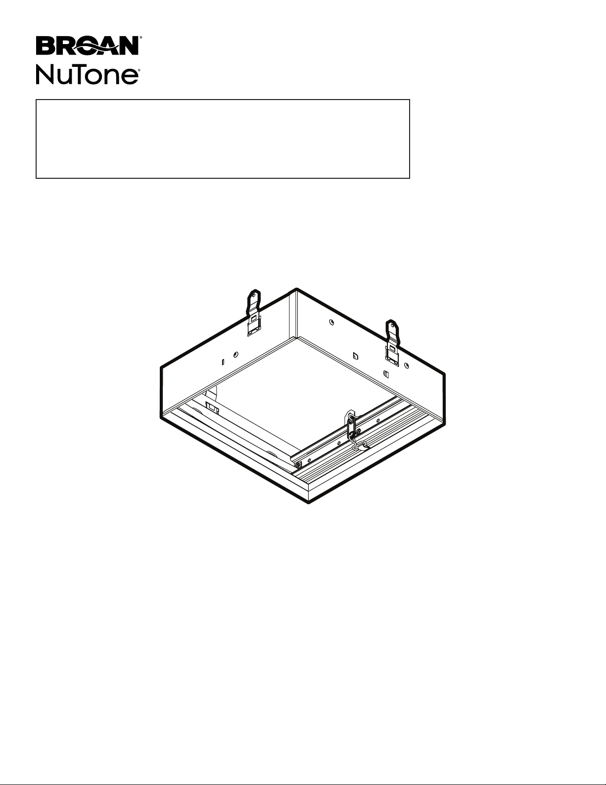
Premium
Radiation Damper
INSTALLATION GUIDE
Easy installation
© 2019 Broan-NuTone LLC
Page 2
Page 2
RDFUWT – Installation Guide
Usage
For use with 1, 2, or 3-Hour-Rated Floor-Ceiling and Roof-Ceiling Designs.
UL/ cUL Listed for use in the following Floor Ceiling and Roof Ceiling Assemblies: L521, L528, L546, L558,
L562, L574, L576, L581, L583, L585, P522, P533, P538, P545, and P547 when installed per the following
instructions:
Flat Ceiling / Horizontal Mount Only.
For use with the following ventilation fan models:
Broan XB50, XB50L, XB50L1, XB80, XB80L, XB80L1, XB110, XB110L, XB110L1, XB110H, XB110HL,
XB110HL1, ZB80, ZB80M, ZB110, ZB110H, ZB110M, ZB80L, ZB80L1, ZB80ML, ZB80ML1, ZB110L, ZB110L1,
ZB110HL, ZB110HL1, ZB110ML, ZB110ML1, QT130E, QT130LE, QT140E, QT140LE, QTXE150, QTXE150FLT,
QTXE110150DC, QTXE110150DCL, QTXE110150DCS, QTXE110150DCSL
Broan Canada XB50C, XB90C, XB90LC, XB90HC, XB110C, XB110LC, XB110HC, ZB110C, ZB90C, ZB110LC, ZB90LC, ZB110HC, ZB110MC,
ZB90MC, ZB90HC, ZB110MLC, ZB90MLC
NuTone QTN130E, QTN130LE1, QTXEN150, QTXEN150FLT, XN50, XN50L, XN80, XN80L, XN110, XN110L, XN110H, XN110HL, ZN80,
ZN80M, ZN110, ZN110H, ZN110M, ZN80L, ZN80ML, ZN110L, ZN110HL, ZN110ML
NuTone Canada XN50C, XN90C, XN110C, XN90LC, XN90HC, XN110LC, XN110HC, ZN90C, ZN90LC, ZN90HC, ZN90MC, ZN90MLC,
ZN110C, ZN110LC, ZN110HC, ZN110MC, ZN110MLC
Twin City T080E, T110E, T150LP
PennBarry ZQ80-GPE, ZQ110-GPE, ZQ80L-GPE, ZQ110L-GPE
York CIQ80-GPE, CIQ110-GPE, CIQ80L-GPE, CIQ110L-GPE
SEE DETAILS ON
UL CLASSIFICATION
MARKING ON PRODUCT
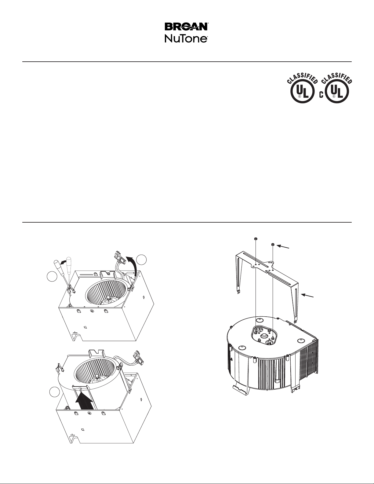
Prepare Fan
The following steps are best performed on a work surface
before fan installation. Protect counter tops by placing
corrugated sheet under the fan.
1
2
3
B
A
1. Remove blower and all packing material from fan
housing.
2. Assemble SUPPORT BRACKET (A) (supplied with
radiation damper) to fan blower as shown. Secure the
bracket to motor studs with (2) #8-32 HEX NUTS (B)
supplied in radiation damper parts bag.
Page 3
Page 3
C
RDFUWT – Installation Guide
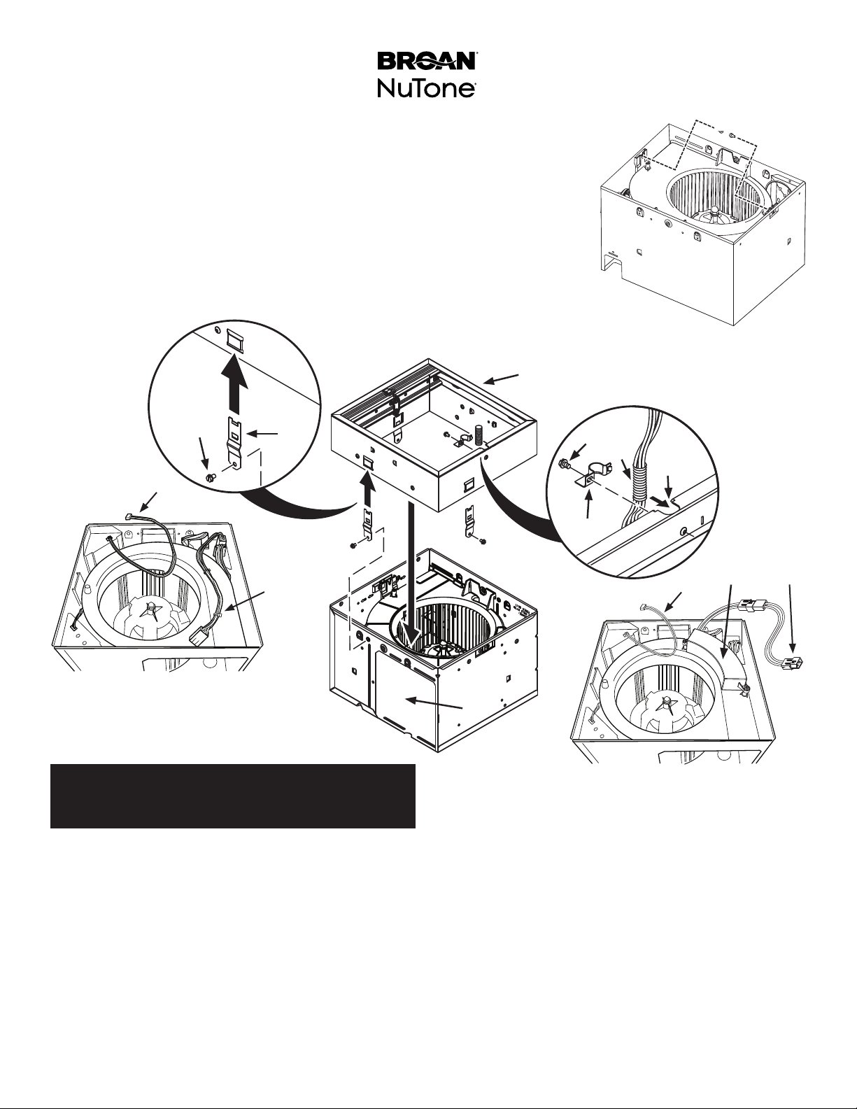
3. Reinstall blower into fan housing. Install (2) #8 x ½” HEX HEAD SHEET METAL SCREWS
(C) supplied in fan parts bag.
4. Slide (4) MOUNTING BRACKETS (D) into slots on four sides of RADIATION DAMPER
EXTENSION FRAME (E). Make sure they snap into place and are securely engaged after
assembly.
5. Center the radiation damper over the fan housing. Make sure NOTCH (F) is correctly
positioned relative to the DUCT CONNECTOR OPENING (G).
6. Align radiation damper mounting bracket with (4) dimples in fan housing.
7. Secure brackets to fan housing using (4) #8 X 3/8” SELF-DRILLING SHEET
METAL SCREWS (H) (supplied in radiation damper parts bag) inserted through
dimples in housing.
E
H
D
I *
C
H
L
F
K
FANS WITH INCANDESCENT
OR FLUORESCENT LIGHTS
I * Jumper for Motion or
Humidity-Sensing units only.
Steps 8 through 12:
Lighted Fans, Humidity-Sensing Fans, or
Motion Sensing Fans ONLY.
For fans not equipped with a light, a humidity sensor or a
motion sensor: Skip to Step 13.
8. Make lead wires longer. Purchase jumper kit model
RDJUMPU or RDJUMPU1 from your local BroanNuTone dealer or distributor.
Each kit contains:
1 - Jumper for lighted fan models
1 - Jumper for sensor fan models
9a. For fans equipped with incandescent or fluorescent
9b. For fans equipped with LED lights, connect one end
lights, connect one end of the LIGHTING JUMPER
(K) to mating connector in the fan’s wiring box.
of the LIGHTING JUMPER (K) to mating connector
from LED DRIVER (J).
M
J
K
I *
G
FANS WITH LED LIGHTS
I * Jumper for Motion or
Humidity-Sensing units only.
9c. For fans equipped with humidity or motion sensors,
connect one end of the SENSOR JUMPER (I) to
mating connector in the fan’s wiring box.
10. Route JUMPER(S) (I) (K) towards the NOTCH (F) in
the damper frame.
11. Press jumper wires into PLASTIC SPLIT TUBE
INSULATOR (L) (supplied in damper parts bag). Push
plastic split tubing into NOTCH (F) opening.
12. Align tab on CABLE CLAMP (M) with mating slot in
damper extension. Secure clamp with supplied (4) #8
X 3/8” SELF-DRILLING SHEET METAL SCREWS
(H).
Page 4

Page 4
O
P
RDFUWT – Installation Guide
L
T
INSERT
TAB INTO
SLOT IN
HOUSING
TOP AND BOTTOM FLANGES
REMAIN OUTSIDE OF HOUSING
snap!
snap!
Step 13:
XB, ZB, XN, ZN Models ONLY
13. Slide MOUNTING FRAME (O) onto fan housing. Pull
frame up around housing until it snaps into place.
Secure mounting frame to fan housing with (2) #8
X 3/8” FLAT HEAD SHEET METAL SCREWS (P)
supplied in the fan parts bag.
R
Q
S
SCREW FROM
PARTS BAG
15. Install 6” DUCT CONNECTOR (T) to fan housing and
secure with screw supplied in fan parts bag.
Step 14:
QT Models ONLY
14. Attach MOUNTING CHANNELS (Q) to housing using
SCREWS (R) supplied in fan parts bag.
Insert SLIDE BRACKETS (S) into mounting channels.
Page 5
Page 5
ON-CENTER
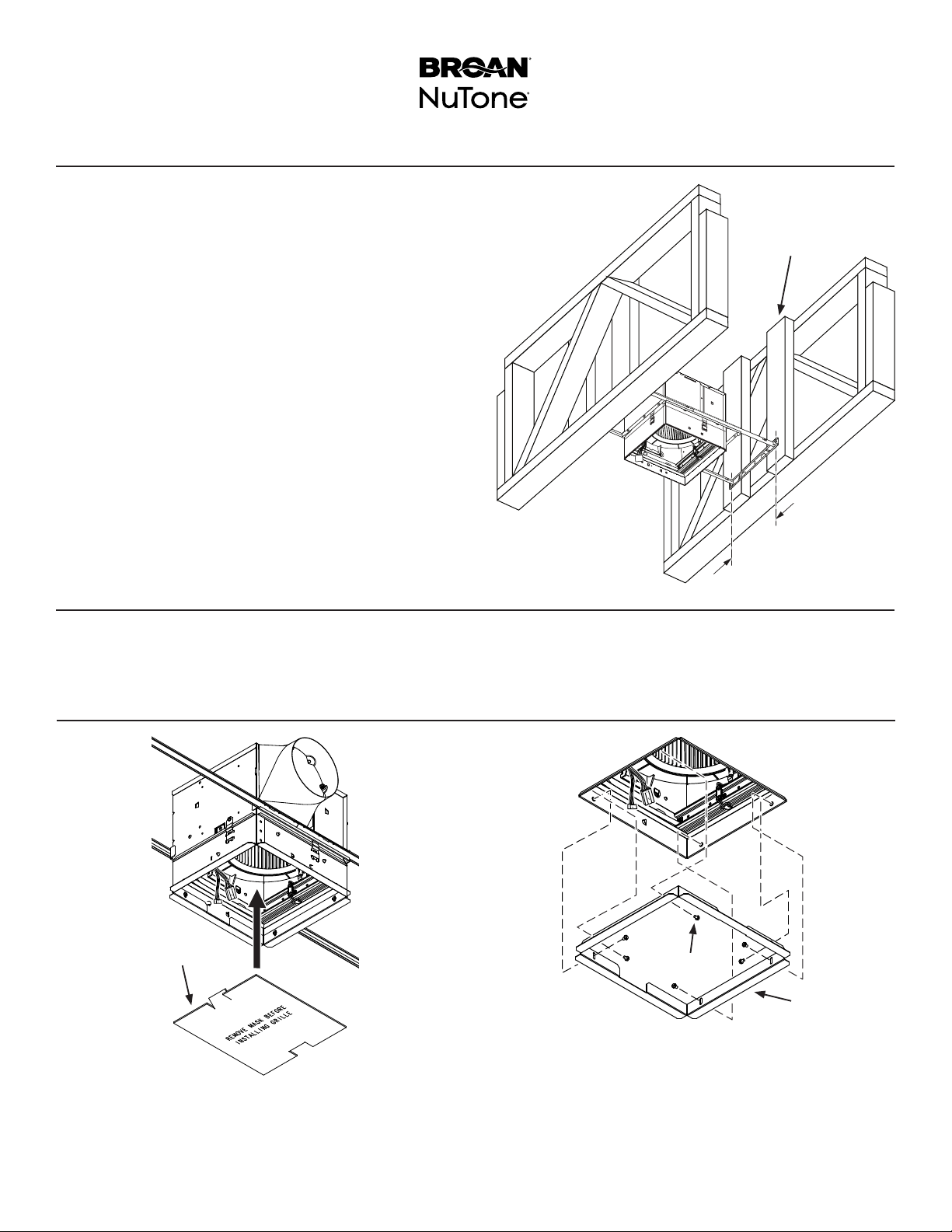
Prepare Ceiling & Install Fan in Ceiling
This radiation Damper and Fan Combination is UL/ cUL
Listed for use in the following Floor Ceiling and Roof
Ceiling Assemblies: L521, L528, L546, L558, L562, L574,
L576, L581, L583, L585, P522, P533, P538, P545, and
P547.
16. Install additional 2 X 4 VERTICAL BLOCKS (U) as
shown.
17. Make sure lower edge of radiation damper is flush
with INTERIOR SIDE OF FINISHED CEILING.
18. Securely fasten mounting support brackets to (4)
vertical blocks.
19. Attach round metal duct to the duct connector
and discharge air to an outside location. Seal all
connection joints with duct tape.
RDFUWT – Installation Guide
U
12”
Connect Wiring
20. Refer to instructions supplied with the fan for various
electrical wiring configurations.
Finish Installation
V
X
W
21. Install MASK (V) supplied with the fan to protect damper
and fan from drywall spray, construction dust, etc.
22. Finish ceiling around radiation damper opening. Ceiling
opening must be no larger than the outside of the
radiation damper.
23. Remove MASK (V) from housing.
24. Fasten (2) PLASTER SUPPORTS (W) to the
radiation damper extension with (6) #8 X 3/8” SELF-
DRILLING SHEET METAL SCREWS (X). (Supplied
in radiation damper parts bag.)
Page 6
Page 6
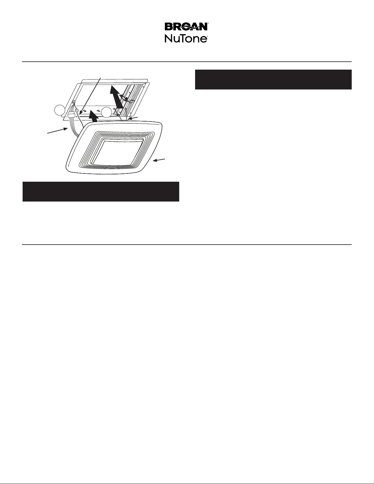
Install Grille
RDFUWT – Installation Guide
I
1
2
Y
K
Z
Step 25:
Lighted Fans ONLY.
25. Attach connector from the LIGHT JUMPER WIRE (K)
to mating connector(s) from the grille.
Service Feature For Fans
Step 26:
Humidity-Sensing Fans and Motion Sensing Fans ONLY.
26. Connect SENSOR JUMPER WIRE (I) into the sensors
connector located on the grille.
27. Squeeze 2 GRILLE SPRINGS (Y) and slide into tabs
on the radiation damper frame. Push GRILLE (Z) until
it’s tight against ceiling surface.
If additional clearance is required between ceiling and
grille, replace grille springs with longer ones (provided
in parts bag).
If your ventilation fan needs service, the inner damper can
be removed from the outer frame without disturbing the
surrounding ceiling material.
Remove the grille and disconnect all electrical connections
from the grille.
Remove (4) screws, then lower the inner damper to access
ventilation fan. Replace the inner damper before operating fan.
99045952F
Page 7

LIRE ET CONSERVER CES INSTRUCTIONS
Installateur : Laisser ce manuel au propriétaire.
Pour consulter l’énoncé de garantie, commander des pièces de rechange, communiquer
avec le soutien technique ou enregistrer le produit, visiter le site Web ou téléphoner.
Aux États-Unis : Broan.com, 1 800 558 1711 ou NuTone.com, 1 888 336 6151.
Au Canada : Broan.ca ou NuTone.ca, 1 877 896 1119
RDFUWT
Registre coupe-feu
haut de gamme
GUIDE D’INSTALLATION
Installation facile
© Broan-NuTone LLC, 2019
Page 8

Page 8
RDFUWT – Guide d’installation
Compatibilité
Pour assemblages plafond/plancher ou toiture/plafond présentant une résistance au feu de 1, 2 ou 3 heures.
Homologation UL/cUL pour utilisation avec les assemblages plafond/plancher et toiture/plafond L521,
L528, L546, L558, L562, L574, L576, L581, L583, L585, P522, P533, P538, P545 et P547 lorsqu’installé
conformément aux instructions.
Fixation à plat à l’horizontale et au plafond.
Compatible avec les modèles de ventilateurs suivants :
Broan XB50, XB50L, XB50L1, XB80, XB80L, XB80L1, XB110, XB110L, XB110L1, XB110H, XB110HL,
XB110HL1, ZB80, ZB80M, ZB110, ZB110H, ZB110M, ZB80L, ZB80L1, ZB80ML, ZB80ML1, ZB110L, ZB110L1,
ZB110HL, ZB110HL1, ZB110ML, ZB110ML1, QT130E, QT130LE, QT140E, QT140LE, QTXE150, QTXE150FLT,
QTXE110150DC, QTXE110150DCL, QTXE110150DCS et QTXE110150DCSL
Broan Canada XB50C, XB90C, XB90LC, XB90HC, XB110C, XB110LC, XB110HC, ZB110C, ZB90C, ZB110LC, ZB90LC, ZB110HC, ZB110MC,
ZB90MC, ZB90HC, ZB110MLC et ZB90MLC
NuTone QTN130E, QTN130LE1, QTXEN150, QTXEN150FLT, XN50, XN50L, XN80, XN80L, XN110, XN110L, XN110H, XN110HL, ZN80,
ZN80M, ZN110, ZN110H, ZN110M, ZN80L, ZN80ML, ZN110L, ZN110HL et ZN110ML
NuTone Canada XN50C, XN90C, XN110C, XN90LC, XN90HC, XN110LC, XN110HC, ZN90C, ZN90LC, ZN90HC, ZN90MC, ZN90MLC,
ZN110C, ZN110LC, ZN110HC, ZN110MC et ZN110MLC
Twin City T080E, T110E et T150LP
PennBarry ZQ80-GPE, ZQ110-GPE, ZQ80L-GPE et ZQ110L-GPE
York CIQ80-GPE, CIQ110-GPE, CIQ80L-GPE et CIQ110L-GPE
VOIR LE DÉTAIL DE LA
CLASSIFICATION UL
SUR LE PRODUIT
Préparer le ventilateur
Idéalement, effectuer les étapes suivantes sur une surface
de travail avant d’installer le ventilateur. Protéger la surface
avec un carton ondulé.
1
2
3
B
A
1. Retirer l’emballage et sortir le ventilateur du boîtier.
2. Placer le SUPPORT (A) (fourni avec le registre
coupe-feu) sur le ventilateur, comme l’indique
l’image, et le fixer aux vis du moteur avec 2 ÉCROUS
HEXAGONAUX No 8-32 (B) provenant du sac de
pièces du registre coupe-feu.
Page 9

Page 9
C
RDFUWT – Guide d’installation
3. Réinstaller le ventilateur dans le boîtier et le fixer avec 2 VIS À TÔLE À TÊTE HEXAGONALE No 8 DE
½ po (C) provenant du sac de pièces du ventilateur.
4. Glisser les 4 LANGUETTES DE FIXATION (D) dans les fentes de chaque côté du CHÂSSIS
D’EXTENSION DU REGISTRE COUPE-FEU (E) jusqu’à ce qu’elles se verrouillent en place; vérifier
qu’elles sont bien fixées.
5. Aligner le châssis du registre coupe-feu et le boîtier du ventilateur. S’assurer que l’ENTAILLE (F) est
bien positionnée par rapport à l’OUVERTURE DE CONNEXION DU CONDUIT (G).
6. Alignez les supports de montage du registre coupe-feu avec les (4) alvéoles du boîtier du
ventilateur.
7. Fixez les supports au boîtier du ventilateur à l’aide de (4) VIS À TÔLE AUTO-PERCEUSES
#8-32 X 3/8 PO (H) (fournies dans le sac de pièces du registre coupe-feu) insérées dans les
alvéoles
E
H
D
I *
C
H
L
F
K
VENTILATEURS AVEC ÉCLAIRAGE
INCANDESCENT OU FLUORESCENT
* Raccordement pour détecteur de mouvement
ou d’humidité seulement.
Étapes 8 à 12
Ventilateurs avec éclairage ou détecteur de
mouvement ou d’humidité SEULEMENT.
Pour les autres ventilateurs, passer à l’étape 13.
8. Allonger les fils de sortie. Acheter un ensemble de
raccordement RDJUMPU ou RDJUMPU1 auprès d’un
détaillant ou d’un distributeur Broan/NuTone.
Chaque ensemble comprend :
1 raccordement pour ventilateur avec éclairage
1 raccordement pour ventilateur avec détecteur
9a. Pour les ventilateurs avec éclairage incandescent
9b. Pour les ventilateurs avec éclairage à DEL,
ou fluorescent, brancher une extrémité du
RACCORDEMENT D’ÉCLAIRAGE (K) sur le bon
connecteur dans la boîte de jonction du ventilateur.
brancher une extrémité du RACCORDEMENT
D’ÉCLAIRAGE(K) sur le bon connecteur du
PILOTEDEL (J).
M
J
I *
G
VENTILATEURS AVEC ÉCLAIRAGE À DEL
*Raccordement pour détecteur de mouvement
ou d’humidité seulement.
9c. Pour les ventilateurs avec détecteur de mouvement
ou d’humidité, brancher une extrémité du
RACCORDEMENT DE DÉTECTEUR (I) sur le bon
connecteur dans la boîte de jonction du ventilateur.
10. Passer les RACCORDEMENTS (I et K) jusqu’à
l’ENTAILLE (F) dans le châssis du registre coupe-feu.
11. Insérer les raccordements dans la GAINE FENDUE
EN PLASTIQUE (L) provenant du sac de pièces
du registre coupe-feu. Insérer la gaine fendue en
plastique dans l’ENTAILLE (F).
12. Aligner la languette du COLLIER DE CÂBLE (M) et
la fente du châssis d’extension du registre coupefeu. Fixer le collier avec une (4) VIS À TÔLE AUTO-
PERCEUSES #8-32 X 3/8 PO (H) fournie.
K
Page 10

Page 10
O
P
RDFUWT – Guide d’installation
L
T
INSÉRER LA
LANGUETTE
DANS LA
FENTE DU
BOÎTIER
LES SAILLIES SUPÉRIEURE
ET INFÉRIEURE RESTENT À
snap!
Clic!
L’EXTÉRIEUR DU BOÎTIER
Étape 13
Modèles XB, ZB, XN et ZN SEULEMENT.
13. Glisser le CHÂSSIS DE MONTAGE (O) sur le boîtier
du ventilateur et le remonter jusqu’à ce qu’il se
verrouille en place.
Fixer le châssis de montage au boîtier du ventilateur
avec 2 VIS À TÔLE No 8 À TÊTE PLATE DE 3/8 po (P)
provenant du sac de pièces du ventilateur.
R
Q
S
VIS DU SAC
DE PIÈCES DU
VENTILATEUR
15. Installer un RACCORD DE CONDUIT DE 6 po (T)
sur le boîtier du ventilateur et le fixer avec une vis
provenant du sac de pièces du ventilateur.
Étape 14
Modèle QT SEULEMENT
14. Fixer les RAILS DE MONTAGE (Q) au boîtier avec les
VIS (R) provenant du sac de pièces du ventilateur.
Insérer les RAILS LATÉRAUX (S) sur les rails de
montage.
Page 11

Pa g e 11
Préparer le plafond et y installer le ventilateur
Cet ensemble de registre coupe-feu et de ventilateur est
homologué UL/cUL pour utilisation avec les assemblages
plafond/plancher ou toiture/plafond suivants : L521, L528,
L546, L558, L562, L574, L576, L581, L583, L585, P522,
P533, P538, P545 et P547.
16. Installer des 2 X 4 VERTICAUX (U), comme sur
l’image.
17. Aligner le bas du registre coupe-feu et la SURFACE
INTÉRIEURE DU PLAFOND FINI.
18. Fixer les rails latéraux aux 2 x 4 verticaux (4).
19. Installer un conduit rond en métal sur le
raccordement de conduit et faire sortir l’air à
l’extérieur du bâtiment. Sceller tous les joints avec du
ruban adhésif en toile.
RDFUWT – Guide d’installation
U
Brancher les fils
20. Pour connaître les différentes configurations du câblage
électrique, consulter les instructions du ventilateur.
Terminer l’installation
V
ENTRAXE
X
W
21. Installer le MASQUE (V) fourni avec le ventilateur pour
protéger le registre coupe-feu et le ventilateur des
éclaboussures de plâtre, des poussières de construction, etc.
22. Finir le plafond autour de l’ouverture du registre coupe-feu.
L’ouverture ne doit pas être plus grande que l’extérieur du
registre coupe-feu.
23. Retirer le MASQUE (V) du boîtier.
24. Fixer les 2 SUPPORTS POUR PLÂTRE (W) au
châssis d’extension du registre coupe-feu avec 6VIS
À TÔLE AUTO-PERCEUSES #8-32 X 3/8 PO (X) provenant
du sac de pièces du registre coupe-feu.
Page 12

Page 12
Installer la grille
RDFUWT – Guide d’installation
I
1
2
Y
K
Z
Étape 25
Ventilateurs avec éclairage SEULEMENT.
25. Brancher le RACCORDEMENT D’ÉCLAIRAGE(K)
sur le bon connecteur de la grille. Step 26:
Entretien et réparation du ventilateur
Étape 26
Ventilateurs avec détecteur de mouvement ou
d’humidité SEULEMENT.
26. Brancher le RACCORDEMENT DE DÉTECTEUR (I)
sur le bon connecteur de la grille.
27. Pincer les 2 RESSORTS DE LA GRILLE (Y) et insérer
leurs embouts dans les fentes du châssis du registre
coupe-feu. Pousser la GRILLE (Z) jusqu’à ce qu’elle
soit bien appuyée au plafond.
Au besoin, utiliser les ressorts plus longs fournis dans
le sac de pièces.
Pour entretenir ou réparer le ventilateur sans endommager
le plafond, retirer la section intérieure du registre coupe-feu
du châssis extérieur.
Retirer la grille et débrancher les raccordements électriques.
Retirer les 4 vis et descendre la section intérieure du registre
coupe-feu pour accéder au ventilateur. Replacer la section
intérieure avant de refaire fonctionner le ventilateur.
99045952F
Page 13

LEA Y CONSERVE ESTAS INSTRUCCIONES
Instalador: Deje esta guía con el dueño de la casa.
Si desea consultar la declaración de garantía, repuestos de servicio, apoyo técnico o para registrar su
producto, visite nuestro sitio web o llame: En Estados Unidos: - Broan.com 800-558-171 or NuTone.com
888-336-6151. En Canadá - Broan.ca or NuTone.ca 877-896-1119
RDFUWT
Regulador de radiación
deprimera calidad
GUÍA DE INSTALACIÓN
Instalación sencilla
© 2019 Broan-NuTone LLC
Page 14

Página 14
Guía de instalación del RDFUWT
Uso
Para usarse en los diseños de piso a cielo raso y techo a cielo raso con clasificación de 1, 2 o 3 horas.
Tiene certificación de UL/ cUL para usarse en los siguientes conjuntos de cielo raso a piso y cielo raso a techo: L521,
L528, L546, L558, L562, L574, L576, L581, L583, L585, P522, P533, P538, P545 y P547 al instalarlo según las siguientes
instrucciones:
Solamente montaje horizontal / en cielo raso plano.
Para usarse con los siguientes modelos de ventilador:
Broan XB50, XB50L, XB50L1, XB80, XB80L, XB80L1, XB110, XB110L, XB110L1, XB110H, XB110HL,
XB110HL1, ZB80, ZB80M, ZB110, ZB110H, ZB110M, ZB80L, ZB80L1, ZB80ML, ZB80ML1, ZB110L, ZB110L1,
ZB110HL, ZB110HL1, ZB110ML, ZB110ML1, QT130E, QT130LE, QT140E, QT140LE, QTXE150, QTXE150FLT,
QTXE110150DC, QTXE110150DCL, QTXE110150DCS, QTXE110150DCSL
Broan Canada XB50C, XB90C, XB90LC, XB90HC, XB110C, XB110LC, XB110HC, ZB110C, ZB90C, ZB110LC, ZB90LC,
ZB110HC, ZB110MC, ZB90MC, ZB90HC, ZB110MLC, ZB90MLC
NuTone QTN130E, QTN130LE1, QTXEN150, QTXEN150FLT, XN50, XN50L, XN80, XN80L, XN110, XN110L, XN110H, XN110HL, ZN80, ZN80M, ZN110,
ZN110H, ZN110M, ZN80L, ZN80ML, ZN110L, ZN110HL, ZN110ML
NuTone Canada XN50C, XN90C, XN110C, XN90LC, XN90HC, XN110LC, XN110HC, ZN90C, ZN90LC, ZN90HC, ZN90MC, ZN90MLC, ZN110C, ZN110LC,
ZN110HC, ZN110MC, ZN110MLC
Twin City T080E, T110E, T150LP
PennBarry ZQ80-GPE, ZQ110-GPE, ZQ80L-GPE, ZQ110L-GPE
York CIQ80-GPE, CIQ110-GPE, CIQ80L-GPE, CIQ110L-GPE
VEA LOS DETALLES
EN LA MARCA DE
CLASIFICACIÓN UL
DELPRODUCTO
Preparación del ventilador
Los siguientes pasos se realizan mejor sobre una superficie
de trabajo antes de instalar el ventilador. Proteja las cubiertas
colocando una hoja corrugada debajo del ventilador.
1
2
3
B
A
2. Monte el SOPORTE DE APOYO (A) (suministrado con el
regulador de radiación) en el soplador del ventilador, como
se muestra. Asegure el soporte a los montantes del motor
con dos (2) TUERCAS HEXAGONALES #8-32 (B) que se
suministran en la bolsa de piezas del regulador de radiación.
1. Retire el soplador y todo el material de embalaje de la cubierta
del ventilador.
Page 15

Página 15
C
Guía de instalación del RDFUWT
3. Reinstale el soplador en la cubierta del ventilador. Instale dos (2) TORNILLOS DE CHAPA
METÁLICA DE CABEZA HEXAGONAL #8 x ½pulg. (C) que se suministran en la bolsa de
piezas del ventilador.
4. Deslice cuatro (4) SOPORTES DE MONTAJE (D) en las ranuras en cuatro lados del MARCO
DE EXTENSIÓN DEL REGULADOR DE RADIACIÓN (E). Después del montaje, asegúrese de
que encajen a presión en su lugar y se enganchen de forma segura.
5. Centre el regulador de radiación sobre la cubierta del ventilador. Asegúrese de que la
MUESCA (F) esté colocada correctamente en relación con la ABERTURA DEL CONECTOR
DE CONDUCTO (G).
6. Alinee el soporte de montaje del amortiguador de radiación con (4) hoyuelos en la carcasa del
ventilador.
7. Asegure los soportes a la carcasa del ventilador utilizando (4) TORNILLOS DE CHAPA
AUTOPERFORANTES # 8 X 3/8 ”(H) (suministrados en la bolsa de piezas del amortiguador de
radiación) insertados a través de hoyuelos en la carcasa.
E
H
D
I *
C
H
L
F
K
VENTILADORES CON LUCES
INCANDESCENTES O FLUORESCENTES
I * Puente solo para unidades con sensor
de movimiento o de humedad.
Pasos 8 a 12:
SOLAMENTE ventiladores con luz, ventiladores consensor
de humedad y ventiladores con sensor demovimiento.
Para ventiladores que no estén equipados con luz, sensor de
humedad o sensor de movimiento: Diríjase al paso12.
8. Alargue los cables principales. Adquiera el juego de puentes
modelo RDJUMPU o RDJUMPU1 con su distribuidor o
concesionario local autorizado de Broan-NuTone.
Cada juego contiene:
1 - puente para los modelos de ventilador con luz
1 - puente para los modelos de ventilador con sensor
9a. Para ventiladores equipados con luces incandescentes
9b. Para ventiladores equipados con luces LED, conecte un
o fluorescentes, conecte un extremo del PUENTE DE
ILUMINACIÓN (K) al conector correspondiente en la caja
de cableado del ventilador.
extremo del PUENTE DE ILUMINACIÓN (K) al conector
correspondiente del CONTROLADOR DE LED (J).
M
J
I *
G
VENTILADORES CON LUCES LED
I * Puente solo para unidades con
sensor de movimiento o de humedad.
9c. Para ventiladores equipados con sensores de humedad
o de movimiento, conecte un extremo del PUENTE DEL
SENSOR (I) al conector correspondiente en la caja de
cableado del ventilador.
10. Tienda los PUENTES (I) (K) hacia la MUESCA (F) en el
marco del regulador.
11. Presione los cables puente en el AISLANTE DE TUBO
DIVIDIDO DE PLÁSTICO (L) (suministrado en la bolsa de
piezas del regulador). Empuje el tubo dividido de plástico
dentro de la abertura de la MUESCA (F).
12. Alinee la lengüeta de la ABRAZADERA DEL CABLE (M)
con la ranura correspondiente en la extensión del regulador.
Fije la abrazadera con el
AUTOPERFORANTES # 8 X 3/8 ”(H)
(4) TORNILLOS DE CHAPA
suministrado.
K
Page 16

Página 16
L
P
O
cilc!
Paso 13:
SOLAMENTE modelos XB, ZB, XN, ZN
13. Deslice el MARCO DE MONTAJE (O) en la cubierta del
ventilador. Suba el marco alrededor de la cubierta hasta que
quede sujetado a presión.
Guía de instalación del RDFUWT
T
INTRODUZCA LA
PESTAÑA EN
LA RANURA DE
LA CUBIERTA
LAS BRIDAS SUPERIOR E INFERIOR
PERMANECEN FUERA DE LA CUBIERTA
TORNILLO DE
LA BOLSA
DE PIEZAS
Fije el marco de montaje a la cubierta del ventilador con
dos (2) TORNILLOS DE CHAPA METÁLICA DE CABEZA
PLANA #8 X 3/8 pulg. (P) que se suministran en la bolsa de
piezas del ventilador.
R
Q
S
Paso 14:
SOLAMENTE modelos QT
14. Sujete los CANALES DE MONTAJE (Q) a la cubierta con
los TORNILLOS (R) que se suministran en la bolsa de
piezas del ventilador.
15. Instale el CONECTOR DE CONDUCTO DE 6 pulg. (T) en la
cubierta del ventilador y asegúrelo con el tornillo incluido en la
bolsa de piezas del ventilador.
Introduzca los SOPORTES DESLIZANTES (S) en los
canales de montaje.
Page 17

Página 17
ON-CENTER
Prepare el cielo raso e instale allí el ventilador
La combinación de regulador de radiación y ventilador tiene
certificación de UL/cUL para usarse en los siguientes conjuntos
de cielo raso a piso y cielo raso a techo: L521, L528, L546, L558,
L562, L574, L576, L581, L583, L585, P522, P533, P538, P545 y
P547.
16. Instale BLOQUES VERTICALES 2x4 adicionales(U), como
se muestra.
17. Asegúrese de que el borde inferior del regulador de radiación
esté al ras con el LADO INTERIOR DEL CIELO RASO
TERMINADO.
18. Fije con firmeza los soportes de montaje de apoyo en los
cuatro (4) bloques verticales.
19. Fije el conducto metálico redondo al conector para conductos
y haga que se descargue el aire en un lugar en el exterior.
Selle todas las juntas de conexión con cinta para conductos.
Guía de instalación del RDFUWT
U
12”
Conecte el cableado
20. Consulte las instrucciones suministradas con el ventilador
para ver las diferentes configuraciones de cableado eléctrico.
Termine la instalación
V
X
W
23. Retire la COBERTURA (V) de la cubierta.
21. Instale la COBERTURA (V) suministrada con el ventilador a fin
de proteger el regulador y el ventilador contra los rociados de
yeso, polvos de construcción, etc.
22. Termine el cielo raso alrededor de la abertura del regulador.
La abertura del cielo raso no debe ser más grande que el
exterior del regulador de radiación.
24. Fije dos (2) SOPORTES DE YESO (W) a la extensión del
regulador de radiación con seis (6)
AUTOPERFORANTES # 8 X 3/8 ”
bolsa de piezas del regulador de radiación.)
TORNILLOS DE CHAPA
(X). (Se suministran en la
Page 18

Página 18
Instale la rejilla
Guía de instalación del RDFUWT
I
1
2
Y
K
Z
Paso 25:
SOLAMENTE ventiladores con luz.
25. Fije el conector del CABLE PUENTE DE LA LUZ (K) a los
conectores correspondientes de la rejilla.
Función de servicio para ventiladores
Paso 26:
SOLAMENTE ventiladores con sensor de humedad y
ventiladores con sensor de movimiento
26. Conecte EL CABLE DE PUENTE DEL SENSOR (I) en el
conector del sensor ubicado en la rejilla.
27. Comprima 2 RESORTES DE LA REJILLA (Y) y deslícelos
dentro de las lengüetas del marco del regulador de radiación.
Empuje la REJILLA (Z) hasta que esté firme contra la superficie
del cielo raso.
Si es necesaria una mayor separación entre el cielo raso y la
rejilla, reemplace los resortes de la rejilla por unos más largos
(suministrados en la bolsa de piezas).
Si su ventilador necesita servicio de reparación/mantenimiento, es
posible quitar el regulador interior del marco exterior sin perturbar
el material del cielo raso circundante.
Quite la rejilla y desconecte todas sus conexiones eléctricas.
Quite los cuatro (4) tornillos y luego baje el regulador interior para
tener acceso al ventilador. Reinstale el regulador interior antes de
activar el ventilador.
99045952F
Page 19

Page 20

99045952F
 Loading...