

Page 1
INSTALLATION INSTRUCTIONS
READ & SAVE THESE INSTRUCTIONS
WARNING
TO REDUCE THE RISK OF FIRE, ELECTRIC SHOCK, OR
INJURY TO PERSONS, OBSERVE THE FOLLOWING:
1. Use this unit only in the manner intended by the manufacturer. If
you have questions, contact the manufacturer at the address or
telephone number listed in the warranty.
2. Before servicing or cleaning unit, switch power off at service
panel and lock service disconnecting means to prevent power
from being switched on accidentally.
When the service
disconnecting means cannot be locked, securely fasten a
prominent warning device, such as a tag, to the service panel.
3. Installation work and electrical wiring must be done by qualified
personnel in accordance with all applicable codes and
standards, including fire-rated construction.
4. Sufficient air is needed for proper combustion and exhausting of
gases through the flue (chimney) of fuel burning equipment to
prevent back drafting. Follow the heating equipment manufacturer's
guideline and safety standards such as those published by the
National Fire Protection Association (NFPA), and the American
Society for Heating, Refrigeration and Air Conditioning
Engineers (ASHRAE), and the local code authorities.
5. When cutting or drilling into wall or ceiling, do not damage
electrical wiring and other hidden utilities.
6. Ducted fans must always be vented to the outdoors.
7. If this unit is to be installed over a tub or shower, it must be
marked as appropriate for the application.
8. Never place a switch where it can be reached from a tub or shower.
9. When applicable local regulations comprise more restrictive
installation and/or certification requirements, the aforementioned
requirements prevail on those of this document and the installer
agrees to conform to these at his own expenses.
10. When performing installation, servicing or cleaning this unit, it is
recommended to wear safety glasses and gloves.
CAUTION
For general ventilating use only. Do not use to exhaust hazardous
or explosive materials and vapors.
INSTALLATION INSTRUCTIONS
•
Suitable for use with solid state speed controls
•
Uses standard 3¼" x 10" ducting
•
Designed for ceiling installation
•
Do not mount over bathtub or shower stall enclosure
•
Not for use in kitchens
•
The ventilator consists of the housing, mounting brackets, junction box,
power unit/blower assembly, damper section and grille assembly
FAN MUST NOT BE INSTALLED IN A CEILING THERMALLY
INSULATED TO A VALUE GREATER THAN R-40.
FOR BEST RESULTS
•
When installing the ventilator in a new construction site, install the
housing during the rough-in construction of the building. The power
unit and grille should be installed after the finished ceiling is in place.
•
To install the ventilator in an existing building, an accessible area
(attic or crawl space) is required from above the planned location.
QuieTTest
®
Twin Blower Ventilator
MODELS: QT200 & QT300
For Ceiling Installation
INSTALLATION
IN A NEW CONSTRUCTION SITE
PREPARATION
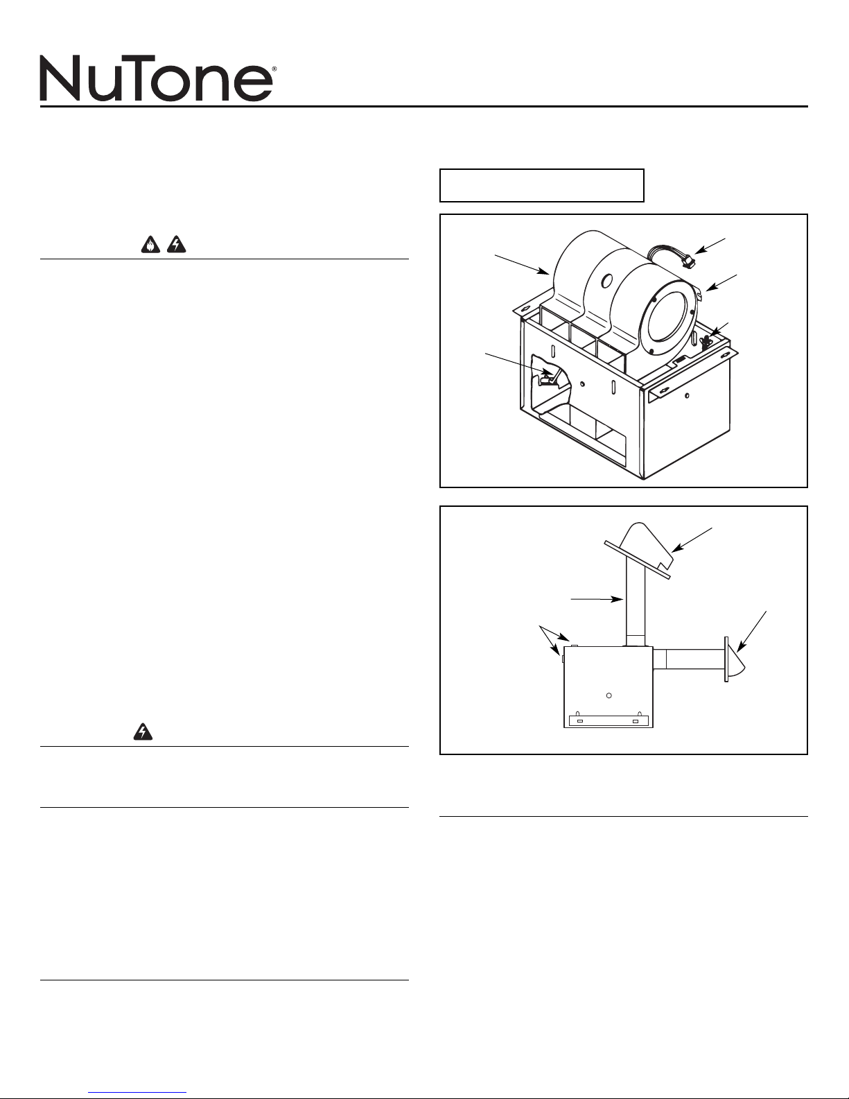
CAUTION: When handling the power unit do not reach in the end
openings and bend the blower wheels.
Refer to Figure 1.
1. Remove power unit from housing assembly.
(a) If necessary, unplug power plug from the connector.
(b) Loosen wing nut on hanger rods that hold the power unit.
(c) Unfasten hanger rods from slots and remove power unit.
(d) Set power unit aside until needed.
2. Refer to Figure 2. Remove one of the wiring knockouts from
the housing.
3. The ventilators can be ducted for either vertical or horizontal
discharge.
4. Refer to Figure 3. Mount 3¼" x 10" damper section on top of
housing for vertical discharge or on the side of housing for
horizontal discharge with two screws (included).
FIGURE 1
FIGURE 2
POWER
UNIT
ROOF CAP
VERTICAL
DISCHARGE
3¼" x 10"
DUCT
KNOCKOUTS
FAN
HOUSING
HORIZONTAL
DISCHARGE
WALL CAP
POWER
CONNECTOR
SLOTS
WING NUT,
HANGER ROD
HANGER
ROD
85669000C
Register your product online
at www.nutone.ca
1
BD0009
BH0039
Page 2
BO0013
MOUNTING THE HOUSING
NOTE: These ventilators are designed for installation between
16" O.C. ceiling joists with no framing necessary. If the
building structure has 24" O.C. joists construction, framing
will be required.
1. Position housing between ceiling joists and adjust height to
finished ceiling. Loosen two hex nuts for each mounting bracket
from inside the housing and make the adjustment. Tighten the
four hex nuts.
NOTE: There are four additional mounting slots in the
housing for mounting or relocating the mounting brackets.
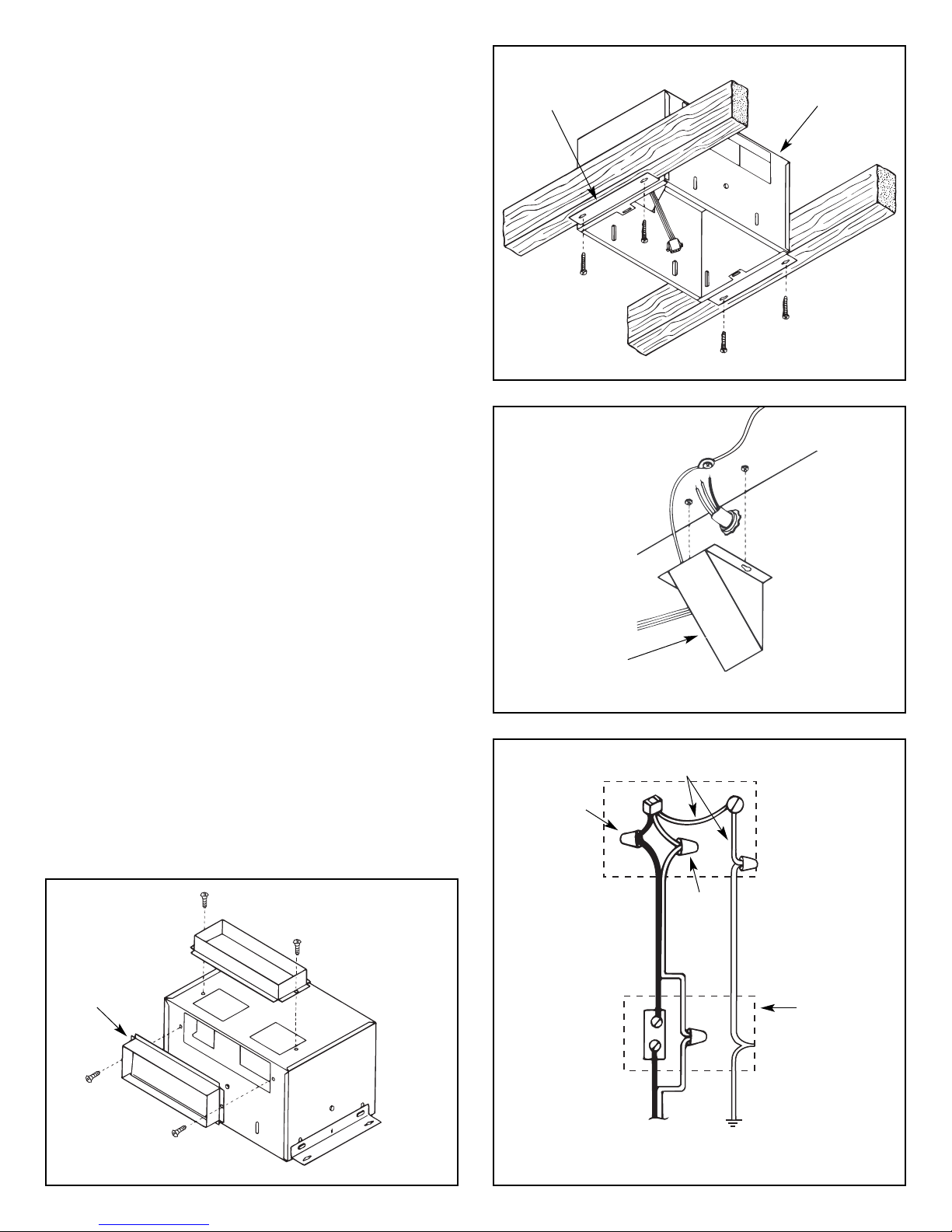
2. Refer to Figure 4. Screw housing to joists using holes
in mounting brackets and four screws (included).
3. Install standard 3¼" x 10" ductwork from damper section
to outside wall or through roof and mount appropriate wall or
roof cap (not included). Refer to the instructions provided with
the caps.
IMPORTANT: Ensure there are no obstructions at the
discharge of the ventilator. Ensure insulation does not get
into the ductwork or into the blower.
WIRING
NOTE: All wiring connections must comply with local codes,
ordinances and the National Electrical Code and the ventilator
must be properly grounded. Disconnect power at circuit
breaker before making wire connections.
1. Refer to Figure 5. Loosen screws and remove junction box.
2. Run 120 VAC supply wiring with ground through switch box to
knockout in ventilator housing and secure with box connector.
3. Refer to Figure 6. Connect supply wires to ventilator wires:
BLACK to BLACK, WHITE to WHITE. Connect ground wire to
GREEN ground lead.
4. Reinstall junction box and tighten screws.
5. Connect supply wire to switch.
NOTE: Switch must be purchased separately. Refer to
NuTone's catalog.
POWER UNIT INSTALLATION
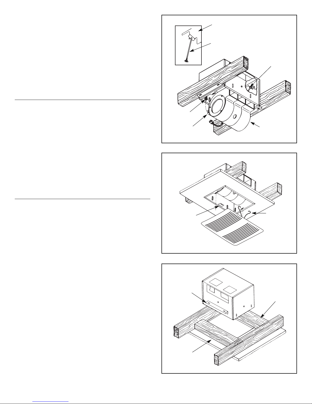
1. Refer to Figure 7. The power unit mounts with two hanger rods
to the mounting brackets. Start threading wing nuts (included)
onto hanger rods. Insert the hanger rods through the holes in
the mounting bracket hooking them from the inside to the
outside.
2. Position the power unit so that its discharge opening is in line
with the installed ductwork. Hold the power unit in position
between the mounting brackets and swing the hanger rods into
the slots on the power unit and securely tighten the wing nuts.
3. Plug the three wire connectors from the junction box into the
wire receptacle connector from the power unit making sure the
plug is properly aligned.
FIGURE 4
FIGURE 5
FIGURE 6
MOUNTING
BRACKET
VENTILATOR
HOUSING
JUNCTION
BOX
GREEN
WHITE
SWITCH
BOX
120 VAC, 60 Hz
HOUSE POWER
STANDARD
WALL SWITCH
EARTH
GROUND
BLACK
FIGURE 3
VERTICAL DISCHARGE
3¼" x 10" DAMPER SECTION
3¼" x 10"
DAMPER
SECTION
HORIZONTAL
DISCHARGE
2
BH0040
BJ0004
BE0010
Page 3
GRILLE INSTALLATION
1. Refer to Figure 8. Squeeze grille mounting springs and insert
into slots in the housing.
2. Press grille firmly into place against ceiling.
MAINTENANCE
•
WARNING: Risk of fire or electrical shock; disconnect the power
before cleaning or performing any maintenance on the ventilator.
•
If the grille becomes soiled, use only a mild soap and water
solution for cleaning. Do not use solvents or abrasive cleaners.
INSTALLATION
IN EXISTING CONSTRUCTION
Installing a ventilator in an existing construction site requires at
least a small accessible area (attic or crawl space) above the
planned installation location.
Review “INSTALLATION IN A NEW CONSTRUCTION SITE” and
follow all instructions which apply to your installation.
Locate the ventilator next to a ceiling joist.
Plan the ductwork and wiring before proceeding with the installation.
CAUTION: Check the area above the planned installation to
ensure that:
1. Ductwork can be installed or that the area is sufficient for proper
mounting.
2. Wiring can be run to the planned location.
3. No wiring or other obstruction will interfere with the installation.
INSTALLATION FROM ACCESSIBLE
AREA ABOVE (USING HEADERS)
1. From below the installation site, drill a small hole in ceiling at the
planned location.
2. Locate hole in attic or crawl space.
3. In attic or crawl space, mark ceiling for cutout by using the housing
as a template. Cutout dimensions: 10
3
⁄16" x 141⁄2". The short side
(10
3
⁄16") of the cutout must be right next to the ceiling joist.
4. Refer to Figure 9. Mark cutout along marked line.
NOTE: If ceiling is plaster, cutout should be made from
below to avoid chipping plaster.
5. Install headers between joists using nails or screws leaving
10
3
⁄16" between them.
6. Install brackets upside down on housing's long dimension using
hex nuts.
7. Mount damper section to housing, install housing and connect
wiring and ductwork. Install power unit/blower assembly and
grille.
FIGURE 7
FIGURE 8
FIGURE 9
MOUNTING
BRACKET
HOOK HANGER
RODS FROM INSIDE
TO OUTSIDE
HANGER ROD
POWER UNIT
SLOT
HANGER
ROD
MOUNTING
SPRING
MOUNTING
BRACKET
HEADER
HEADER
SPRING
MOUNTING
CLIP
3
BD0010
BO0014
BH0041
Page 4

BROAN-NUTONE CANADA INC.
ONEY
EAR LIMITED WARRANTY
Broan-Nutone Canada warrants to the original consumer purchaser of its product that such products will be free from defects in materials and
workmanship for a period of one (1) year from the date of the original purchase. THERE ARE NO OTHER WARANTIES, EXPRESSED OR IMPLIED,
INCLUDING, BUT NOT LIMITED TO, IMPLIED WARRANTIES OF MERCHANTABILITY OR FITNESS FOR A PARTICULAR PURPOSE.
During this one-year period, Broan-NuTone Canada will, at its option, repair or replace, without charge, any product or part which is found to be
defective under normal use and service.
THIS WARRANTY DOES NOT EXTEND TO FLUORESCENT LAMP STARTERS OR TUBES, BULBS OR BATTERIES, FILTERS, DUCT, ROOF
CAPS, WALL CAPS AND OTHER ACCESSORIES FOR DUCTING. This warranty does not cover (a) normal maintenance and service or (b) any
products or parts which have been subject to misuse, negligence, accident, improper maintenance or repair (other than by Broan-NuTone Canada or an
authorized representative), faulty installation or installation contrary to recommended installation instructions.
The duration of any implied warranty is limited to the one-year period as specified for the express warranty.
BROAN-NUTONE CANADA’S OBLIGATION TO REPAIR OR REPLACE, AT BROAN-NUTONE CANADA’S OPTION, SHALL BE THE PURCHASER’S
SOLE AND EXCLUSIVE REMEDY UNDER THIS WARANTY. BROAN-NUTONE CANADA SHALL NOT BE LIABLE FOR INCIDENTAL,
CONSEQUENTIAL OR SPECIAL DAMAGES ARISING OUT OF OR IN CONNECTION WITH PRODUCT USE OR PERFORMANCE. This warranty
supersedes all prior warranties.
To qualify for warranty service, you must (a) notify Broan-NuTone Canada at the address or telephone number stated below (b) give the model number
and part identification and (c) describe the nature of any defect in the product or part. At the time of requesting warranty service, you must present
evidence of the original purchase date.
Date of installation Builder or Installer
Model Number and Product Description
IF YOU NEED ASSISTANCE OR SERVICE
For the location of your nearest Broan-NuTone Canada Inc. dealer:
Dial toll free: 1-888-882-7626
Please be prepared to provide:
Product model number • Date and proof of purchase • The nature of the difficulty
Broan-NuTone Canada Inc.
1140, Tristar Drive, Mississauga (Ontario) L5T 1H9
www.nutone.ca
Product specifications subject to change without notice.
4
Page 5

DIRECTIVES D'INSTALLATION
LIRE ET CONSERVER CES DIRECTIVES
AVERTISSEMENT
POUR RÉDUIRE LES RISQUES D’INCENDIE, D’ÉLECTROCUTION
OU DE BLESSURES CORPORELLES, OBSERVEZ LES
DIRECTIVES SUIVANTES :
1.N’utilisez cet appareil que de la façon prévue par le manufacturier.
Si vous avez des questions, contactez le manufacturier à l’adresse
ou au numéro de téléphone indiqué dans la garantie.
2.Avant de nettoyer ou de réparer l’appareil, coupez le courant au
panneau d’alimentation et verrouillez-en l’accès afin d’éviter sa
remise en marche accidentelle. Si le panneau d’alimentation ne
peut être verrouillé, apposez un avertissement bien en évidence,
par exemple une étiquette de couleur vive
.
3.Les travaux d’installation et de raccordement électrique doivent
être effectués par du personnel qualifié en respectant les
normes et règlements en vigueur, y compris les normes et codes
de bâtiment en matière de prévention d’incendie.
4.Une circulation d’air efficace est requise afin d’assurer la
combustion et l’évacuation complète des gaz par la cheminée des
équipements à combustion pour prévenir les retours de cheminée.
Conformez-vous aux instructions et aux standards de sécurité des
manufacturiers d’équipement de chauffage, tels qu’ils sont publiés
par la
National Fire Protection Association
(NFPA) et l’
American
Society for Heating, Refrigeration and Air Conditioning Engineers
(ASHRAE) ainsi que les responsables des codes locaux.
5.Lorsque vous coupez ou perforez un mur ou un plafond, prenez
garde de ne pas endommager les fils électriques ou autre
installation qui pourraient y être dissimulés.
6. Les ventilateurs avec conduits doivent toujours évacuer l’air à l’extérieur.
7.Si cet appareil doit être installé au-dessus d’une baignoire ou
d’une douche, il doit être conçu pour cette application.
8. Ne jamais installer un interrupteur à portée d’une baignoire ou d’une douche.
9.Lorsqu’une réglementation est en vigueur localement et qu’elle
comporte des exigences d’installation et/ou de certification plus
restrictives, lesdites exigences prévalent sur celles de ce
document et l’installateur entend s’y conformer à ses frais.
10.
Il est recommandé de porter des lunettes et des gants de
sécurité lors de l’installation, de l’entretien ou de la réparation de
cet appareil.
ATTENTION
Pour ventilation générale seulement. Ne l’utilisez pas pour évacuer
des vapeurs ou des matières dangereuses ou explosives.
DIRECTIVES D’INSTALLATION
•
Compatible avec une commande de vitesse à semi-conducteurs
•
Se raccordent à un conduit standard de 3¼po x 10 po
•
Conçus pour une installation au plafond
•
Ne pas installer au-dessus d’une baignoire ou d’une douche
•
Ne pas utiliser dans une cuisine
•
Le ventilateur comprend : le boîtier, les supports de montage, la boîte
de jonction, l’ensemble bloc-moteur/rotors, l’adaptateur/volet et la grille
LE VENTILATEUR NE DOIT PAS ÊTRE INSTALLÉ DANS UN
PLAFOND À ISOLATION THERMIQUE SUPÉRIEURE À R-40.
POUR DE MEILLEURS RESULTATS
•
Lorsqu'on installe le ventilateur dans une construction neuve,
installer le boîtier avant de procéder aux finitions. Le bloc-moteur
et la grille doivent être installés après la finition du plafond.
•
Pour installer le ventilateur dans une construction existante, un
espace accessible au-dessus de l'emplacement choisi pour
l'installation est exigée (grenier ou combles).
Ventilateur QuieTTest
®
à rotor double
MODÈLES : QT200 et QT300
Pour plafond
INSTALLATION
DANS UNE CONSTRUCTION NEUVE
PRÉPARATION
ATTENTION : Lors de la manipulation du bloc-moteur, ne pas le
tenir par les côtés pour ne endommager les roues du ventilateur.
Voir Figure 1.
1. Retirer le bloc-moteur du boîtier.
(a) Au besoin, débrancher le connecteur du bloc moteur.
(b) Desserrer les écrous papillons des tiges de suspension
retenant le bloc-moteur.
(c) Dégager les tiges de suspension des fentes et retirer
le bloc-moteur.
(d) Mettre le bloc-moteur de côté.
2. Voir Figure 2. Défoncer une des ouvertures préamorcées pour
le câblage.
3. Les ventilateurs sont prévus pour une évacuation verticale
ou horizontale.
4. Voir Figure 3. A l'aide des deux vis fournies, assembler
l’adaptateur/volet de 3
¼
po x 10 po sur le dessus du boîtier pour
une évacuation verticale, ou sur le côté du boîtier pour une
évacuation horizontale.
FIGURE 1
FIGURE 2
85669000C
Enregistrez votre produit en
ligne à www.nutone.ca
CAPUCHON DE TOIT
EVACUATION
VERTICALE
CONDUIT DE
3
1
⁄
4
PO x 10 PO
OUVERTURES
PRÉAMORCÉES
BOITIER DU
VENTILATEUR
EVACUATION
HORIZONTALE
CAPUCHON
MURAL
BLOC-MOTEUR
CONNECTEUR
D'ALIMENTATION
FENTES
ECROU
PAPILLON DE
LA TIGE DE
SUSPENSION
TIGE DE
SUSPENSION
1
BD0009
BH0039
Page 6

BO0013
MONTAGE DU BOITIER
NOTE : ces ventilateurs sont conçus pour une installation
sans encadrement entre solives de 16 po d'axe en axe. Si la
structure du bâtiment comporte des solives de 24 po d'axe en
axe, un encadrement sera nécessaire.
1. Placer le boîtier entre les solives de façon à ce qu'il vienne à ras
du plafond quand celui-ci sera fini. Desserrer les deux écrous
hexagonaux de chaque support de montage depuis l'intérieur du
boîtier et ajuster celui-ci. Serrer les quatre écrous hexagonaux.
NOTE : il y a quatre fentes de montage supplémentaires sur
le boîtier pour les supports de montage.
2. Voir Figure 4. Fixer le boîtier aux solives en faisant passer les
quatre vis (fournies) par les orifices des supports de montage.
3. Acheminer le conduit standard de 3
¼
po x 10 po de
l’adaptateur/volet jusqu’au mur extérieur ou à travers le toit, et le
relier à un capuchon mural ou de toit (non inclus). Voir les
instructions comprises avec les capuchons.
IMPORTANT : s'assurer que rien ne gêne l'évacuation du
ventilateur. S'assurer aussi qu'aucun élément d'isolation ne
pénètre dans le conduit ou dans le ventilateur.
CÂBLAGE
NOTE : tous les raccords de câblage doivent respecter les
règlements locaux et le ventilateur doit être convenablement
relié à la terre. Couper le courant avant de faire les raccords
de câblage.
1. Voir Figure 5. Retirer les vis ainsi que la boîte de jonction.
2. Acheminer un câble de 120 V c.a. avec mise à la terre à partir
du boîtier de l’interrupteur jusqu’à la boîte de jonction, au
travers d’un serre-fils installé dans l’ouverture préamorcée.
3. Voir Figure 6. Raccorder les fils d'alimentation aux fils du ventilateur :
le NOIR avec le NOIR, le BLANC avec le BLANC. Reliez le fil de
mise à la terre au fil VERT de mise à la terre du ventilateur.
4. Remettre en place la boîte de jonction et serrer ses vis.
5. Raccorder le câble d'alimentation à l'interrupteur.
NOTE : l'interrupteur doit être acheté séparément. Voir le
catalogue NuTone.
INSTALLATION DU BLOC-MOTEUR
1. Voir Figure 7. Le bloc-moteur s'installe à l'aide de deux tiges de
suspension aux supports de montage. Commencez à visser les
ecrous papillons (fournis) sur les tiges de suspension. Insérer
les tiges de suspension par les orifices du support de montage
en les accrochant de l'intérieur vers l'extérieur.
2. Placer le bloc-moteur de façon à ce que son ouverture
d'évacuation soit alignée avec le conduit installé. Maintenir le
bloc-moteur en place entre les supports de montage et faire
basculer les tiges de suspension dans les fentes du bloc-moteur
puis serrer les écrous papillons.
3. Brancher le connecteur à trois fils provenant de la boîte de
jonction avec la prise du bloc-moteur en s'assurant que le
connecteur soit correctement aligné.
FIGURE 4
FIGURE 5
FIGURE 6
SUPPORT
DE MONTAGE
BOÎTIER DU
VENTILATEUR
BOÎTE DE
JONCTION
VERT
BLANC
BOÎTIER DE
L’INTERRUPTEUR
COURANT DOMESTIQUE
120 V
C.A., 60 Hz
INTERRUPTEUR
MURAL STANDARD
MISE
À LA TERRE
NOIR
FIGURE 3
ÉVACUATION VERTICALE
ADAPTATEUR/VOLET
DE 3¼ PO x 10 PO
ADAPTATEUR/VOLET
DE 3¼ PO x 10 PO
ÉVACUATION
HORIZONTALE
2
BH0040
BJ0004
BE0010
Page 7

INSTALLATION DE LA GRILLE
1. Voir Figure 8. Serrer les ressorts de montage de la grille
et les insérer dans les fentes du boîtier.
2. Appuyer fermement sur la grille pour qu'elle vienne contre
le plafond.
ENTRETIEN
•
ATTENTION : risque d'incendie ou de décharge électrique;
couper le courant avant le nettoyage ou l'entretien du ventilateur.
•
Si la grille se salit, n'utiliser qu'une solution d'eau et de savon
doux pour le nettoyage. Ne pas utiliser de solvant ou de
nettoyant abrasif.
INSTALLATION DANS
UNE CONSTRUCTION EXISTANTE
Pour installer le ventilateur dans une construction déjà existante,
un espace (même petit) accessible au-dessus de l'emplacement
choisi pour l'installation est exigé (grenier ou combles.)
Revoir la section « INSTALLATION DANS UNE CONSTRUCTION
NEUVE » et suivre toutes les instructions qui s’appliquent à votre
installation.
Placer le ventilateur près d'une solive.
Prévoir les conduits et le câblage avant de commencer l'installation.
ATTENTION : inspecter l'espace au-dessus de l'emplacement
prévu pour s'assurer que :
1. Le conduit puisse être installé ou que l'espace soit suffisant
pour une installation adéquate.
2. Le câble puisse être acheminé jusqu'à l'emplacement choisi.
3. Aucun câblage ou autre construction ne gêne l'installation.
INSTALLATION PAR L’ESPACE
ACCESSIBLE AU-DESSUS
(EN UTILISANT DES CHEVÊTRES)
1. Percer un petit trou par en dessous de l’emplacement prévu
du ventilateur.
2. Repérer le trou dans le grenier ou sous les combles.
3. Depuis le grenier ou sous les combles, tracer la découpe en
utilisant le boîtier comme gabarit. Découper aux dimensions :
10
3
⁄16 po x 14½po. La largeur (103⁄16 po) de la découpe doit être
tout contre la solive.
4. Voir Figure 9. Découper en suivant les lignes.
NOTE : si le plafond est en plâtre, la découpe doit
se faire par en dessous pour éviter d'ébrécher le plâtre.
5. Installer les chevêtres entre les solives à l'aide de clous
ou de vis en laissant 10
3
⁄16 po d'espace entre eux.
6. Assembler les supports de montage à l’envers sur la longueur
du boîtier en utilisant les écrous.
7. Assembler l’adaptateur/volet au boîtier, installer le boîtier,
raccorder le câblage et raccorder les conduits. Installer le
bloc-moteur et la grille.
FIGURE 7
FIGURE 8
FIGURE 9
SUPPORT
DE MONTAGE
ACCROCHER LA TIGE DE
SUSPENSION DE L’INTÉRIEUR
VERS L’EXTÉRIEUR
TIGE DE
SUSPENSION
BLOC-MOTEUR
FENTE
TIGE DE
SUSPENSION
RESSORT
DE MONTAGE
SUPPORT
DE MONTAGE
CHEVÊTRE
CHEVÊTRE
CLIP POUR
RESSORT
DE MONTAGE
3
BD0010
BO0014
BH0041
Page 8

BROAN-NUTONE CANADA INC.
G
ARANTIE LIMITÉE DE UN AN
Broan-Nutone Canada garantit à l’acheteur consommateur original de ses produits qu’ils sont exempts de défauts reliés aux matériaux ou à la
main-d’œuvre pour une période de un an à compter de la date d’achat originale. IL N’Y A PAS D’AUTRES GARANTIES, EXPRIMÉES OU
IMPLICITES, Y COMPRIS, MAIS SANS SE LIMITER AUX GARANTIES IMPLICITES POUR FIN DE COMMERCIALISATION ET DE CONVENANCE
DANS UN BUT PARTICULIER.
Pendant cette période de un an, Broan-NuTone Canada, à son choix, réparera ou remplacera gratuitement tout produit ou pièce qui s’avère
défectueux dans des conditions normales d’utilisation et d’entretien.
CETTE GARANTIE NE COUVRE PAS LES STARTERS DE LAMPES FLUORESCENTES OU LES TUBES, LES AMPOULES OU LES PILES, LES
FILTRES, LE CONDUIT, LES CAPUCHONS DE MUR, LES CAPUCHONS DE TOIT ET LES AUTRES ACCESSOIRES DE CONDUIT. Cette garantie
ne couvre pas (a) l’entretien et le service normal ou (b) tout produit ou pièce endommagés par suite de mauvais usage, négligence, accident, entretien
inapproprié ou réparation (autre que celle effectuée par Broan-NuTone Canada ou un représentant autorisé), mauvaise installation ou installation
contraire au mode d’installation recommandé.
La durée de toute garantie implicite est limitée à une période de un an telle qu’il est spécifié pour la garantie exprimée.
L’ENGAGEMENT DE BROAN-NUTONE CANADA DE RÉPARER OU DE REMPLACER, AU CHOIX DE BROAN-NUTONE CANADA, DOIT ÊTRE LA
SEULE OBLIGATION EXCLUSIVE EN VERTU DE CETTE GARANTIE. BROAN-NUTONE CANADA NE DOIT PAS ÊTRE TENUE RESPONSABLE
DES DOMMAGES DIRECTS, INDIRECTS OU SPÉCIAUX SURVENANT À CAUSE DE L’UTILISATION OU DE LA PERFORMANCE DE SES
PRODUITS OU EN RAPPORT AVEC CELLES-CI. Cette garantie annule toutes les garanties précédentes.
Pour obtenir le service après-vente aux fins de la garantie, vous devez (a) aviser Broan-NuTone Canada à l’adresse ou au numéro de téléphone
ci-dessous, (b) donner le numéro du modèle et l’identification de la pièce et (c) décrire la nature de tout défaut du produit ou de la pièce. Lorsque vous
demandez le service après-vente aux fins de la garantie, vous devez présenter une preuve de la date d’achat originale.
Date d’installation Entrepreneur ou installateur
N° de modèle et description du produit
POUR OBTENIR DE L’ASSISTANCE OU DU SERVICE
Pour connaître où se trouve le Centre de services Broan-NuTone Canada Inc. autorisé indépendant le plus près de chez-vous
Composez sans frais : 1 888 882-7626
Veuillez garder à portée de la main :
Le numéro du modèle • la date et preuve d’achat • le type de problème
Broan-NuTone Canada Inc.
1140, Tristar Drive, Mississauga (Ontario) L5T 1H9
www.nutone.ca
Les caractéristiques de produits peuvent changer sans préavis.
4
 Loading...