

Page 1
®
Heat-A-Vent
Combination
INSTALLATION INSTRUCTIONS
READ & SAVE THESE INSTRUCTIONS!
93⁄4”
MODEL: 9905-RO2
FOR BEST RESULTS
In a new construction site, install the housing (complete
with heater and ventilator) during rough-in construction of
the building. The grille should be installed when the finished
ceiling is in place.
Installation in an existing, finished building requires
an accessible area (attic or crawl space) above the
planned location. See “INSTALLATION IN EXISTING
CONSTRUCTION.”
Do not install closer than 12 inches to a vertical surface.
Do not install over tub or shower enclosure.
•
For installation in sloped ceilings up to 12/12 pitch.
• Ductwork must point up.
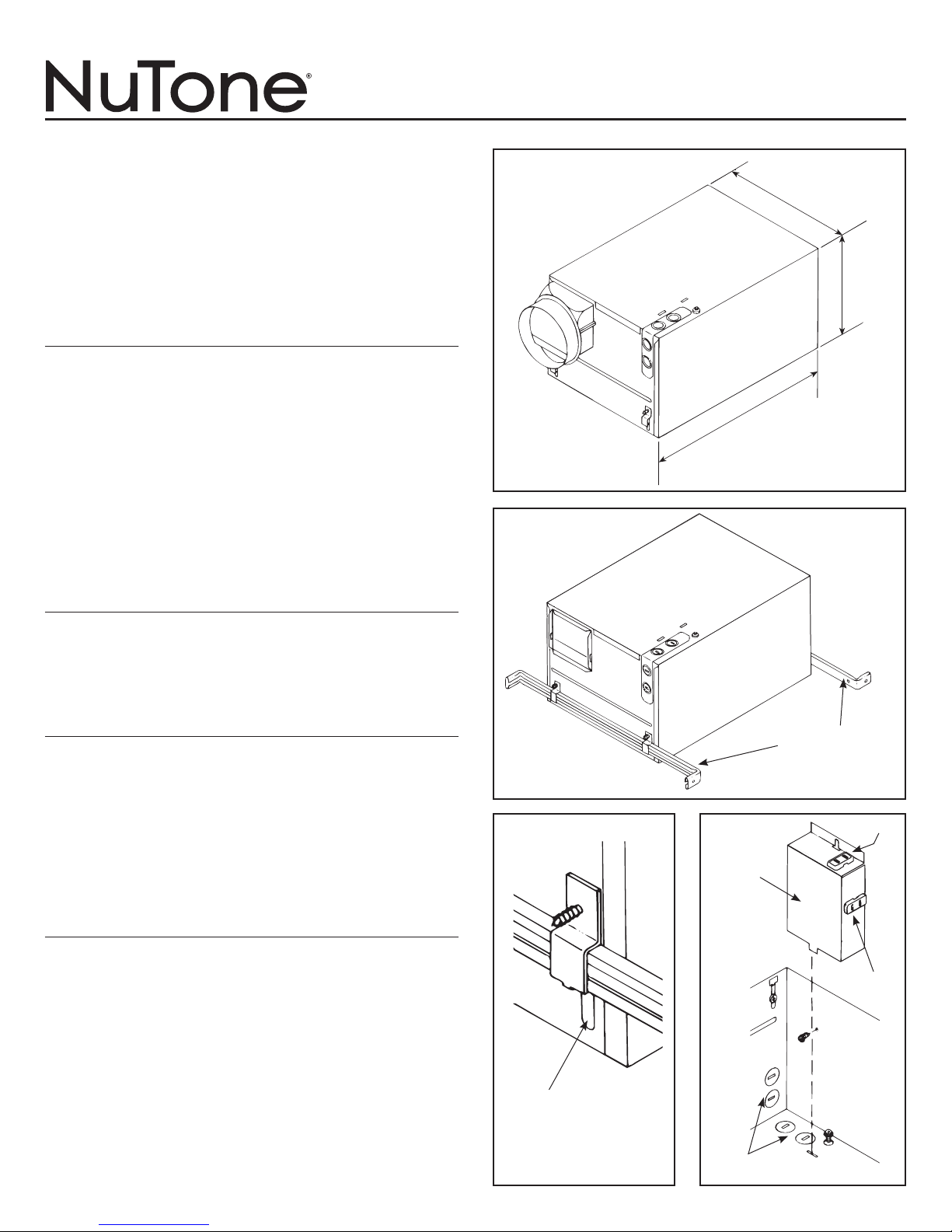
UNIT DIMENSIONS
Refer to Figure 1 for housing’s dimensions.
NOTE: If there will be a finished second floor above,
the Model 9905 housing requires a minimum of 2” x 8”
joist construction for mounting.
73⁄4”
14”
FIGURE 1
WIRING AND DUCTWORK
1. Run the required wiring during rough-in stage of construction.
2. Total connected load: 1630 watts.
3. Plan to run 120vAC, 60 Hz wiring (with ground) on a
separate 20 Amp circuit from a power source, through
the provided wall switch, to the housing’s junction box.
See wiring diagram.
4. Use 4” round duct.
INSTALLATION IN
NEW CONSTRUCTION
PREPARATION
1. Loosen hanger bar brackets to allow bars to be inserted.
2. Refer to Figure 2. Insert hanger bars into brackets.
3. Refer to Figure 3. Slide hanger bar brackets down to end
of slot closest to outside edge of housing. Tighten brackets
in this position.
4. Refer to Figure 4. Remove junction box cover by
removing one screw.
5. Refer to Figure 4. Remove appropriate wiring knockout(s)
and install approved box connector(s).
HANGER BARS
FIGURE 2
VENT
JUNCTION
BOX
COVER
HEAT
ADJUSTMENT
SLOT
KNOCKOUTS
FIGURE 3 FIGURE 4
Page 2
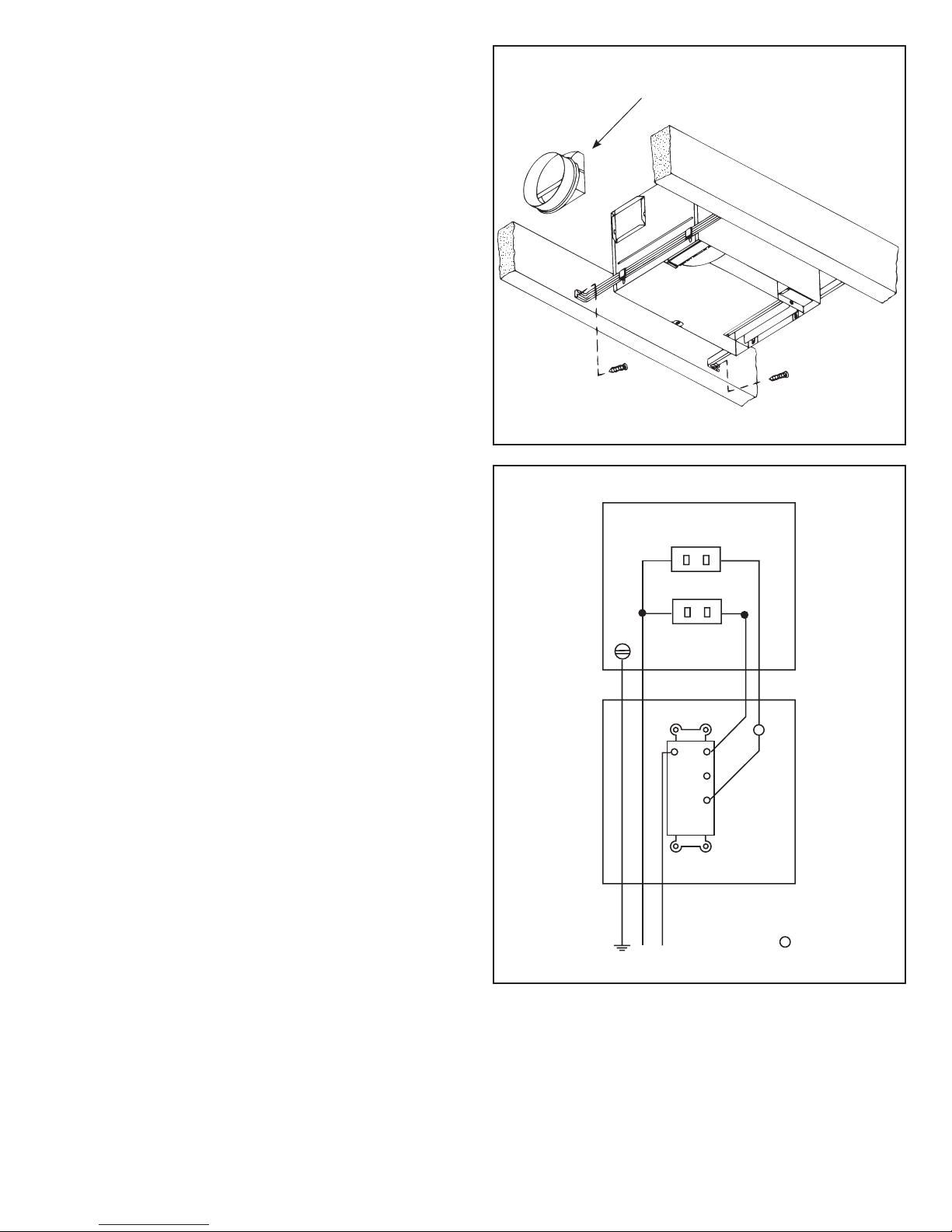
MOUNTING THE HOUSING
HEAT
VENT
HEATER
JUNCTION BOX
HEATER
(WHITE)
RED
WHT
BLU.
WHT
VENT
SWITCH
BOX
120vAC
LINE
GROUND
WHITE
BLACK
T
NOTE:
WHEN THERMOSTAT
OR TIMER IS USED,
CONNECT AT
T
1. Locate housing between joists.
2. Refer to Figure 5. Using nails, secure hanger bars to joists.
NOTE: The hanger bar brackets are adjustable.
Allowing for the thickness of the finished ceiling,
mount hanger bars so that edge of housing will be
flush with the finished ceiling.
3. Adjust brackets as required. Tighten brackets.
INSTALLING THE DUCTWORK
1. Refer to Figure 5. Install duct collar.
2. Using 4” round duct, connect duct to collar and tape
connection.
INSTALLING THE SWITCH
1. Install double-gang switch box in chosen location.
2. Refer to Figure 6. Run wiring and make wiring
connections.
3. Use supplied screws to secure switch bracket assembly
to switch box.
4. Using supplied screws, secure wall plate to switch bracket.
INSTALLING AND CONNECTING THE WIRING
Refer to Figure 6.
All wiring must comply with local codes and unit must
be properly grounded.
1. Using 12-gauge wire, run 120vAC, 60 Hz wiring (with
ground) from a power source to the wall switch location.
The unit must be wired on a separate 20 Amp circuit.
2. Run wiring from switch location to housing as shown in the
wiring diagram.
3. Make wiring connections as shown in wiring diagram.
4. Replace junction box cover. Slide slotted hole in cover
over screw. Tighten screw securely.
5. Secure wire cover with one screw.
6. Insert heater and ventilator plugs into proper receptacles
as shown.
DUCT COLLAR
FIGURE 5
MOUNTING THE GRILLE ASSEMBLY
1. Refer to Figure 7. Using two screws (provided), secure
grille to housing.
FIGURE 6
Page 3

INSTALLATION IN
EXISTING CONSTRUCTION
In an existing, finished building, installation of the HeatVent Combination requires an accessible area (attic or crawl
space) above the planned location. If the location that has
been chosen for installation has a finished floor above it,
be certain there is sufficient space available to install the
housing and make the necessary duct connection.
PLANNING
Review “INSTALLATION IN NEW CONSTRUCTION” and
follow all instructions that apply.
CAUTION: Check the area above the planned location
to make sure that:
(1) Ducting can be installed or that the area is sufficient for
proper venting.
(2) Wiring can be run to the planned location.
(3) No wiring or other obstructions might interfere with
the installation.
INSTALLATION
1. The housing must be mounted between ceiling joists.
2. Refer to Figure 8. Mark ceiling for cutout.
Cutout dimensions: 141⁄8” long x 97⁄8” wide. Make cutout
in ceiling.
3. Follow steps under “PREPARATION” page 1.
4. From above, lower housing into the cutout and secure
hanger brackets. Install duct collar, connect duct, and
run wiring through box connectors.
5. From below, adjust housing so that it is flush with the
finished ceiling.
6. From below, make wiring connections as shown in figure
6.
7. Replace junction box cover.
8. Insert heater and ventilator plugs into proper receptacles.
9. Install grille.
GRILLE
FIGURE 7
141⁄8”
NOTE: This heater is provided with a Self-Hold resetable
thermal protector. If the heater shuts off during operation, turn
to off at the wall switch and wait approximately 15 minutes
before turning back on. If heater does not reset or trips
repeatedly, contact a NuTone service center.
97⁄8”
FIGURE 8
Page 4

One Year Limited Warranty
WARRANTY OWNER: Broan-NuTone warrants to the original consumer purchaser of its products that such products will be
free from defects in materials or workmanship for a period of one (1) year from the date of original purchase. THERE ARE
NO OTHER WARRANTIES, EXPRESS OR IMPLIED, INCLUDING, BUT NOT LIMITED TO, IMPLIED WARRANTIES OF
MERCHANTABILITY OR FITNESS FOR A PARTICULAR PURPOSE.
During this one year period, Broan-NuTone will, at its option, repair or replace, without charge, any product or part which is
found to be defective under normal use and service. THIS WARRANTY DOES NOT EXTEND TO FLUORESCENT LAMP
STARTERS OR TUBES, FILTERS, DUCT, ROOF CAPS, WALL CAPS AND OTHER ACCESSORIES FOR DUCTING. This
warranty does not cover (a) normal maintenance and service or (b) any products or parts which have been subject to misuse,
negligence, accident, improper maintenance or repair (other than by Broan-NuTone), faulty installation or installation contrary
to recommended installation instructions.
The duration of any implied warranty is limited to the one year period as specied for the express warranty. Some states do
not allow limitation on how long an implied warranty lasts, so the above limitation may not apply to you.
Broan-NuTone’S OBLIGATION TO REPAIR OR REPLACE, AT Broan-NuTone’S OPTION, SHALL BE THE PURCHASER’S
SOLE AND EXCLUSIVE REMEDY UNDER THIS WARRANTY. Broan-NuTone SHALL NOT BE LIABLE FOR INCIDENTAL,
CONSEQUENTIAL OR SPECIAL DAMAGES ARISING OUT OF OR IN CONNECTION WITH PRODUCT USE OR PERFORMANCE. Some states do not allow the exclusion or limitation of incidental or consequential damages, so the above
limitation or exclusion may not apply to you. This warranty gives you specic legal rights, and you may also have other rights,
which vary from state to state. This warranty supersedes all prior warranties.
WARRANTY SERVICE: To qualify for warranty service, you must (a) notify Broan-NuTone at the address or telephone num-
ber below, (b) give the model number and part identication and (c) describe the nature of any defect in the product or part.
At the time of requesting warranty service, you must present evidence of the original purchase date.
Date of Installation
Builder or Installer
Model No. and Product Description
IF YOU NEED ASSISTANCE OR SERVICE - CONTACT:
Broan-NuTone LLC Hartford, Wisconsin www.nutone.com 888-336-3948
Broan-NuTone Canada Mississauga, Ontario www.nutone.ca 877-896-1119
Rev. 08/2007
Product specifications subject to change without notice.
Printed in Canada, 01/2008, Part No. 100992
 Loading...