

Page 1
INSTALLATION INSTRUCTIONS
READ & SAVE THESE INSTRUCTIONS!
Bulb Heaters & Bulb Heater/Fans
MODELS: 9417DNM, 9420WHC, 9425WHC
IMPORTANT SAFETY INSTRUCTIONS
WARNING – TO REDUCE THE RISK OF FIRE, ELECTRIC SHOCK,
OR INJURY TO PERSONS, OBSERVE THE FOLLOWING:
1. Use this unit only in the manner intended by the manufacturer.
If you have questions, contact the manufacturer at the address
or telephone number listed in the warranty.
2. Before servicing or cleaning unit, switch power off at service
panel and lock service panel to prevent power from being
switched on accidentally. When the service disconnecting
means cannot be locked, securely fasten a prominent warning
device, such as a tag, to the service panel.
3. Installation work and electrical wiring must be done by a qualified person(s) in accordance with all applicable codes and standards, including fire-rated construction codes and standards.
4. Sufficient air is needed for proper combustion and exhausting
of gases through the flue (chimney) of fuel burning equipment
to prevent backdrafting. Follow the heating equipment
manufacturer's guideline and safety standards such as those
published by the National Fire Protection Association (NFPA),
and the American Society for Heating, Refrigeration and Air
Conditioning Engineers (ASHRAE), and the local code authorities.
5. When cutting or drilling into wall or ceiling, do not damage electrical wiring and other hidden utilities.
6. Do not install this unit over a tub or shower.
7. Never place a switch where it can be reached from a tub or
shower.
8. Do not operate unit with dimmer switch or speed control.
CAUTION
1. For general ventilating use only. Do not use to exhaust hazardous or explosive materials and vapors.
2. This product is designed for installation in flat ceilings only.
DO NOT MOUNT THIS PRODUCT IN A WALL.
3. To avoid motor bearing damage and noisy and/or unbalanced
impellers, keep drywall spray, construction dust, etc. off power
unit.
4. Please read specification label on product for further information and requirements.
PLAN THE INSTALLATION
Choose the location for your heater. Refer to Warnings and Cautions.
MODELS 9417DNM & 9425WHC ONLY – The unit will operate
most efficiently when located where the shortest possible duct run
and minimum number of elbows will be needed. Units are designed for use with standard 4" round duct.
Note that two-bulb units can be fitted with one infrared bulb (for
heat) and one reflector bulb (for light). Dual or multi-controls can be
used for separate control of bulbs and/or exhaust fan. Purchase
controls separately.
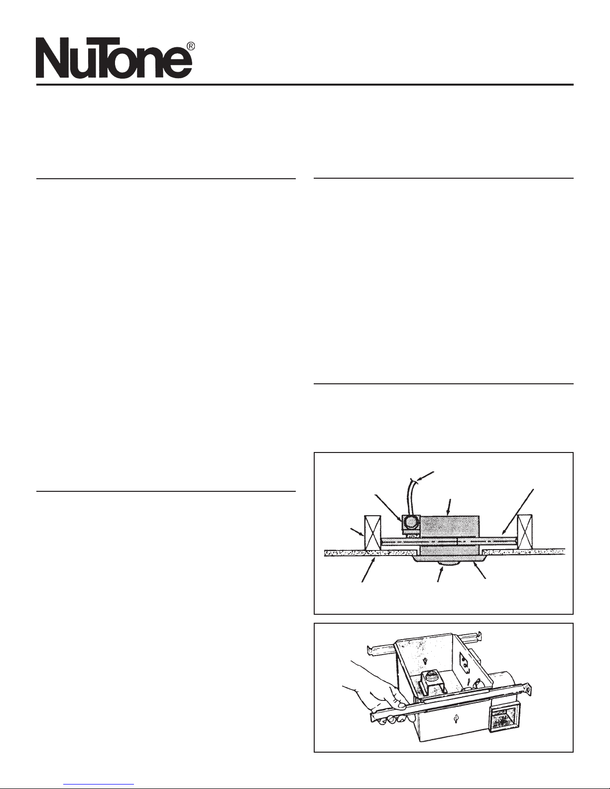
Refer to FIGURE 1
Follow these basic steps when installing this unit:
1. Nail unit to joists.
2. Attach ductwork (Models 9417DNM & 9425WHC only).
3. Connect power cable.
4. Fasten grille to housing.
PREPARE THE HEATER
1. Remove the unit from carton. Save carton for use as plaster
shield in rough-in installations.
Refer to FIGURE 2
2. Slide adjustable mounting brackets into bracket channels on
housing.
DAMPER/DUCT
CONNECTOR
CEILING
JOIST
CEILING MATERIAL BULB(S)
HOUSING
POWER CABLE
GRILLE
MOUNTING
BRACKET
FIGURE 1
FIGURE 2
1
Page 2
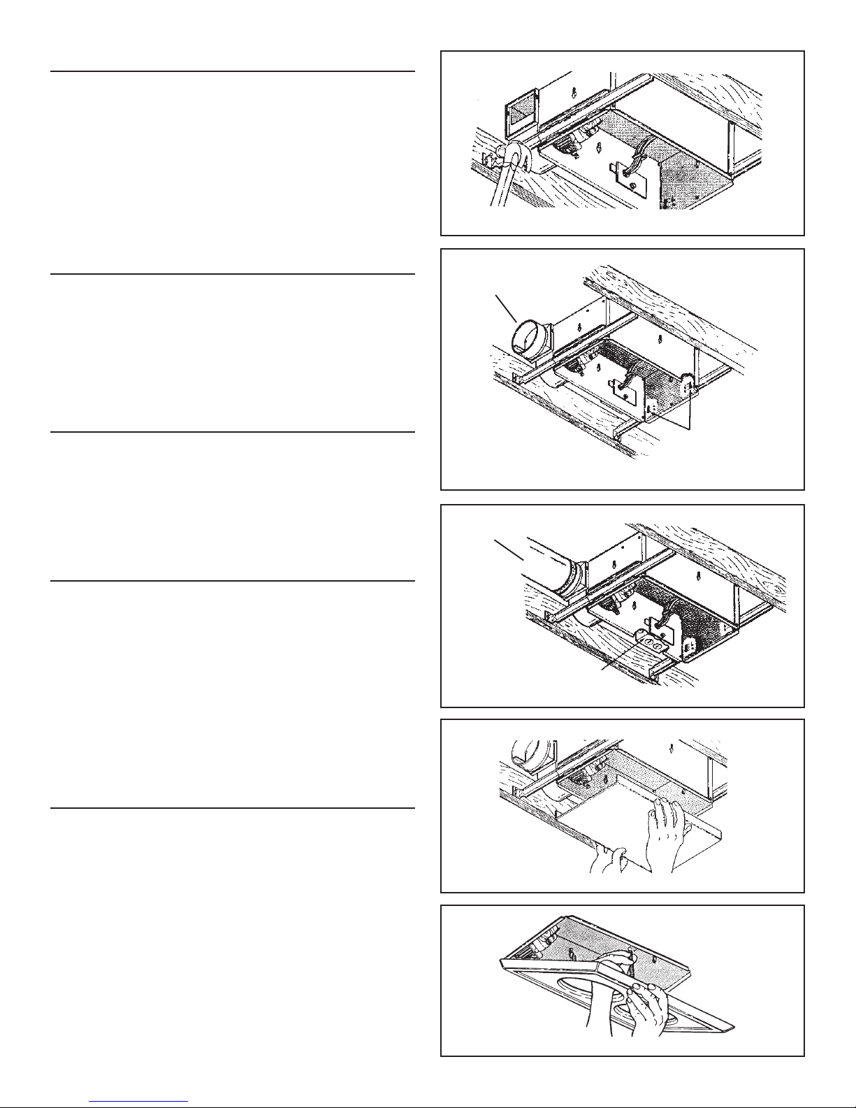
INSTALL THE HEATER
Refer to FIGURE 3
1. Position unit between joists and extend mounting brackets.
2. Nail brackets firmly to joists. Bottom of brackets should be
positioned flush with joist bottom.
Refer to FIGURE 4
3. Brackets are factory-set for ½" thick ceiling material. For thicker
ceilings, loosen 4 vertical adjusting screws and lower housing
to appropriate thickness on gauges. Tighten vertical adjusting
screws firmly.
ATTACH DUCTWORK
(MODELS 9417DNM & 9425WHC ONLY)
Refer to FIGURE 4
1. Snap the damper/duct connector onto housing. Make sure
that tabs on the connector lock in housing slots and that gravity closes damper.
2. Attach 4" round duct to damper/duct connector and run
ductwork to the outside through a roof or wall cap. Check
damper to make sure it opens freely. Tape all joints to make
them secure and air tight.
WIRE THE HEATER
Refer to FIGURE 5
1. Remove wiring box from side of housing. Remove knockout(s)
and connect power cable(s) to wiring box using proper CSA
approved connector.
Refer to FIGURE 6 (on page 3)
2. Wire unit as indicated in appropriate diagram. Push all wiring
into wiring box and replace wiring box onto housing.
FIGURE 3
DAMPER/DUCT
CONNECTOR
VERTICAL ADJUSTING
SCREWS
FIGURE 4
4” ROUND
DUCT
FINAL ASSEMBLY
Refer to FIGURE 7
1. Protect motor, bulb sockets and wiring from construction dust,
drywall spray, paint, etc. by using the plaster shield. Cut it from
the carton and follow directions printed on it.
2. Finish all ceiling work as necessary.
3. Remove plaster shield and check if bottom of housing is flush
with finished ceiling. If not, loosen vertical adjusting screws,
reposition housing, and retighten screws.
Refer to FIGURE 8
4. Attach grille by hooking springs onto clips on side of housing.
5. Install BR40 or R40-size 250W infrared bulb(s). Center grille
around bulb(s).
USE AND CARE
MODELS 9417DNM & 9425WHC OPERATION NOTE: These units
are designed with a thermostat which senses excess heat and
may start the blower automatically. This is normal and is no cause
for concern.
DISCONNECT ELECTRIC POWER SUPPLY AND LOCK OUT
SERVICE PANEL BEFORE CLEANING OR SERVICING THIS
UNIT.
To clean fan assembly: Remove bulb(s). Unhook springs and remove grille. Loosen motor assembly mounting screws and rotate
assembly to remove it from housing. Gently vacuum fan, motor and
interior of housing. Reverse steps to replace fan assembly.
To clean grille assembly: Remove bulb(s). Unhook springs and
remove grille. Clean grille with mild soapy water. Use a mild detergent, such as dishwashing liquid. Dry with a soft cloth. DO NOT
USE ABRASIVE CLOTHS, STEEL WOOL PADS OR SCOURING
POWDERS.
Motor is permanently lubricated — Do not oil or disassemble motor.
WIRING BOX
FIGURE 5
FIGURE 7
FIGURE 8
2
Page 3
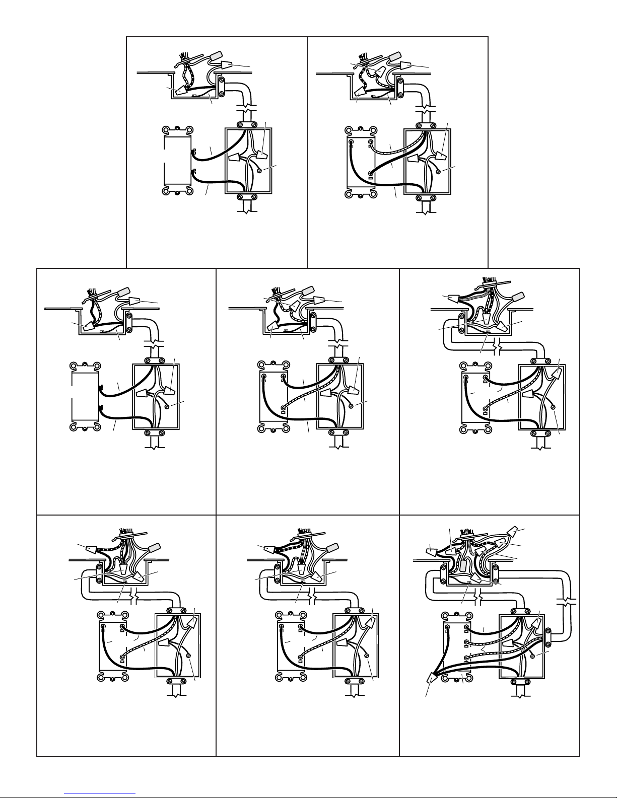
BLACK to
RED & BLUE
WHITE to
WHITE / GRAY
RED TO RED
WHITE to
WHITE / GRAY
BLACK to
BLACK
& RED
SWITCH OR TIMER
GROUND
BLACK
GROUND
BLACK
SWITCH OR TIMER
BLACK
120 VAC LINE IN
MODEL 9417DNM
Lamp & Vent operate together
WHITE to
WHITE / GRAY
WHITE to
WHITE
GROUND
RED to RED
BLACK to BLACK
LIGHT
HEAT
WHITE
to WHITE
GROUND
GROUND
BLACK
BLACK TO BLUE
HEAT
VENT
DUAL CONTROL
GROUND
RED
BLACK
BLACK
MODEL 9417DNM
Lamp & Vent operate separately
WHITE to
WHITE / GRAY
WHITE to
WHITE
RED
GROUND
120 VAC LINE IN
BLACK to BLACK,
& YELLOW
RED to RED
& BLUE
LIGHT
VENT & HEAT
WHITE to
WHITE
GROUND
GROUND
BLACK
3 WHITE / GRAY WIRES
RED
WHITE to
WHITE
BLACK
MODEL 9420WHC
Lamps operate together
BLACK to
BLUE
RED to RED,
BLACK &
YELLOW
GROUND
VENT
HEAT & LIGHT
BLACK
DUAL CONTROL
MODEL 9425WHC
Lamps operate together –
Vent separately
120 VAC LINE IN
3 WHITE / GRAY WIRES
RED
120 VAC LINE IN
WHITE to
WHITE
GROUND
DUAL CONTROL
BLACK
120 VAC LINE IN
MODEL 9420WHC
Lamps operate separately
BLACK to
BLACK, & BLUE
RED to RED
& YELLOW
GROUND
LIGHT
& VENT
HEAT
BLACK
RED
DUAL CONTROL
MODEL 9425WHC
Light & Vent operate together –
Heat separately
3 WHITE / GRAY WIRES
WHITE to
WHITE
GROUND
120 VAC LINE IN
DUAL CONTROL
120 VAC LINE IN
MODEL 9425WHC
Vent & Heat operate together –
Light separately
RED to RED
BLACK to BLACK
LIGHT
HEAT
VENT
3 BLACK WIRES
GROUND
BLACK
RED
3-FUNCTION CONTROL
WHITE to WHITE
RED to BLUE
BLACK to YELLOW
WHITE to WHITE / GRAY
3 WHITE
WIRES
120 VAC LINE IN
MODEL 9425WHC
Light, Vent & Heat operate separately
GROUND
GROUND
3
FIGURE 6
Page 4

PARTS LIST
9420WHC-R01 9425WHC-R01 9417DNM-R01
REF. PART NO. PART NO. PART NO. DESCRIPTION
1 97010320 97010320 97010319 Grille Assembly
(Includes Ref. No. 2)
2 06170-00 06170-00 06170-00 Grille Spring (2 Req.)
3 97009724 97010254 97010254 Motor
4 76230-00 98007352 98007352 Motor Mounting Bracket
5 99770033 99770033 99770033 Bulb Holder
6 99770037 99770037 - - - - Bulb Holder
7 - - - - 97010255 97010255 Blower Wheel
97009762 - - - - - - - - Fan Blade
MODEL 9420WHC-R01
MODEL 9417DNM-R01
3
4
5
2
MODEL 9425WHC-R01
7
WARRANTY
BROAN-NUTONE ONE YEAR LIMITED WARRANTY
Broan-NuTone warrants to the original consumer purchaser of
our products that such products will be free from defects in
materials or workmanship for a period of one year from date of
original purchase. THERE ARE NO OTHER WARRANTIES,
EXPRESSED OR IMPLIED, INCLUDING, BUT NOT LIMITED
TO, IMPLIED WARRANTIES OR MERCHANTABILITY OR FITNESS FOR A PARTICULAR PURPOSE.
During this one-year period, Broan-NuTone will, at our option,
repair or replace, without charge, any product or part which is
found to be defective under normal use and service.
THIS WARRANTY DOES NOT EXTEND TO FLUORESCENT
LAMP STARTERS AND TUBES. This warranty does not cover
(a) normal maintenance and service or (b) any products or parts
which have been subject to misuse, negligence, accident, improper maintenance or repair (other than by us), faulty installation or installation contrary to recommended installation instructions.
The duration of any implied warranty is limited to the one-year
period as specified for the express warranty. Some states do
not allow limitation on how long an implied warranty lasts, so
the above limitation may not apply to you.
BROAN-NUTONE’S OBLIGATION TO REPAIR OR REPLACE,
AT OUR OPTION, SHALL BE THE PURCHASER'S SOLE AND
EXCLUSIVE REMEDY UNDER THIS WARRANTY. BROANNUTONE SHALL NOT BE LIABLE FOR INCIDENTAL, CONSEQUENTIAL OR SPECIAL DAMAGES ARISING OUT OF OR
IN CONNECTION WITH PRODUCT USE OR PERFORMANCE. Some states do not allow the exclusion or limitation of
incidental or consequential damages, so the above limitations
or exclusion may not apply to you.
This warranty gives you specific legal rights, and you may also
have other rights, which vary from state to state. This warranty
supersedes all prior warranties.
To qualify for warranty service, you must (a) notify us at an address stated below or telephone 1-888-882-7626, (b) give the
model number and part identification and (c) describe the nature of any defect in the product or part. At the time of requesting warranty service, you must present evidence of the original
purchase date.
Broan-NuTone Canada, Inc.
1140 Tristar Drive
Mississauga, Ontario L5T 1H9
(1-888-882-7626)
Product specifications subject to change without notice.
1140 Tristar Drive, Mississauga, Ontario L5T 1H9
Printed in U.S.A., 3/02, Part No. 99043014D
4
1
Page 5

INSTRUCTIONS D’INSTALLATION
LISEZ ET CONSERVEZ CES INSTRUCTIONS
Ventilateurs à Lampe Chauffante
et à Éclairage
MODÈLES: 9417DNM, 9420WHC, 9425WHC
IMPORTANTES INSTRUCTIONS
DE SÛRETÉ
AVERTISSEMENT – POUR RÉDUIRE LES RISQUES D’INCENDIE, DE
CHOC ÉLECTRIQUE OU DE BLESSURE, VEUILLEZ OBSERVER LES
CONSIGNES SUIVANTES :
1. N’utilisez cet appareil que de la façon prévue par le fabricant. Pour
toute question, contactez le fabricant à l’adresse ou au numéro de
téléphone figurant dans la garantie.
2. Avant d’effectuer toute réparation ou nettoyage, coupez le courant au
panneau électrique et verrouillez le disjoncteur afin d’éviter que le
courant ne soit rétabli accidentellement. Si le disjoncteur ne peut être
verrouillé, accrochez une affiche ou une étiquette bien en vue sur le
panneau.
3. L’installation et les branchements électriques doivent être effectués
par un personnel compétent, conformément aux normes et aux codes
en vigueur, y compris les normes et les codes du bâtiment relatifs à la
résistance au feu.
4. Assurez un apport d’air suffisant pour la combustion et l’évacuation
adéquates des gaz par la cheminée de tout appareil de chauffage au
mazout et pour éviter les refoulements d’air. Suivez les instructions
du fabricant de l’appareil de chauffage et respectez les normes de
sécurité telles que celles publiées par la National Fire Protection
Association (NFPA), l’American Society for Heating, Refrigeration and
Air Conditioning Engineers (ASHRAE) et les autorités locales.
5. Lors du perçage ou du découpage d’un mur ou d’un plafond, prenez
garde de ne pas endommager le câblage électrique ni aucun élément
dissimulé.
6. N’installez pas cet appareil au-dessus d’une baignoire ou d’une
douche.
7. Ne placez jamais un interrupteur à un endroit accessible d’une
baignoire ou d’une douche.
8. N’actionnez pas cet appareil avec un gradateur ou un variateur de
vitesse.
ATTENTION
1. Cet appareil convient à des fins de ventilation générale uniquement.
Ne l’utilisez pas pour l’évacuation de matières ou de vapeurs
dangereuses ou explosives.
2. Ce produit est concu pour l’installation dans les plafonds plats
seulement. NE PAS POSER CE PRODUIT SUR UN MUR.
3. Pour éviter que les roulements du moteur soient bruyants ou s’abîment,
ou que la roue à ailettes soit déséquilibrée, assurez-vous qu’ils sont
exempts de poussière de plâtre ou de construction.
4. Veuillez lire l’étiquette des caractéristiques techniques du produit pour
de plus amples informations quant aux exigences.
PLANIFICATION DE L’INSTALLATION
Choisissez l’emplacement du ventilateur. Consultez les avertissements et
mises en garde ci-dessus.
MODÈLES 9417DNM ET 9425WHC SEULEMENT – L’appareil sera plus
efficace s’il est raccordé à un minimum de conduits et de coudes. Il est
conçu pour être utilisé avec un conduit rond standard de 4 po (10 cm).
Les appareils à deux ampoules (9420WHC et 9425WHC) peuvent être
équipés d’une lampe infrarouge (pour la chaleur) et d’un projecteur (pour
l’éclairage). Une commande double ou multiple peut commander
séparément les ampoules et le ventilateur. Ces commandes sont vendues
séparément.
Voir FIGURE 1
Lors de l’installation, suivez les étapes ci-dessous :
1. Clouez l’appareil aux solives.
2. Fixez les conduits de ventilation (modèles 9417DNM et 9425WHC
seulement)
3. Raccordez le câble d’alimentation électrique.
4. Fixez la grille au boîtier.
PRÉPARATION DU VENTILATEUR
1. Sortez l’appareil de son emballage. Conservez le carton pour protéger
les lieux contre la poussière de plâtre.
Voir FIGURE 2
2. Glissez les brides de montage réglables dans les rails du boîtier.
CLAPET/
RACCORD DE
CONDUIT
SOLIVE DU
PLAFOND
MATÉRIAU DE
PLAFOND
CÂBLE ÉLECTRIQUE
BOÎTIER
AMPOULE(S)
GRILLE
BRIDE DE
MONTAGE
FIGURE 1
FIGURE 2
5
Page 6

INSTALLATION DU VENTILATEUR
Voir FIGURE 3
1. Positionnez l’appareil entre les solives et allongez les brides de montage.
2. Clouez solidement les brides sur les solives. Assurez-vous que le
bas des brides est à égalité avec le bas des solives.
Voir FIGURE 4
3. Les brides sont réglées à l’usine pour des plafonds de 1/2 po (12 mm)
d’épaisseur. Pour des plafonds plus épais, desserrez les quatre vis
de réglage vertical et abaissez le boîtier à l’épaisseur appropriée
selon les marques de repère. Resserrez fermement les vis.
FIXATION DES CONDUITS
(MODÈLES 9417DNM ET 9425WHC SEULEMENT)
Voir FIGURE 4
1. Enclenchez le clapet/raccord de conduit sur le boîtier. Assurez que
les languettes du raccord sont bien bloquées dans les fentes du
boîtier et que le clapet se referme par gravité.
2. Fixez un conduit rond de 4 po (10 cm) au clapet/raccord de conduit et
acheminez-le jusqu’à l’extérieur à un chapeau de toit ou de mur.
Assurez-vous que le clapet s’ouvre librement. Appliquez du ruban
adhésif sur les joints pour qu’ils soient solides et étanches.
CÂBLAGE DU VENTILATEUR
Voir FIGURE 5
1. Retirez la boîte de connexion du côté du boîtier. Enlevez les pastilles
nécessaires et raccordez les câbles électriques à la boîte de connexion
à l’aide d’un connecteur approprié homologué CSA.
Voir FIGURE 6 (page 7)
2. Branchez les fils tel qu’indiqué dans le diagramme correspondant.
Repoussez tous les fils dans la boîte de connexion et replacez celleci dans le boîtier.
FIGURE 3
CLAPET/RACCORD
DE CONDUIT
VIS DE RÉGLAGE
VERTICAL
FIGURE 4
CONDUIT ROND 4 po (10 cm)
ASSEMBLAGE FINAL
Voir FIGURE 7
1. Protégez le moteur, les réceptacles d’ampoule et les fils contre la
poussière de construction, le plâtre ou la peinture à l’aide de l’écran
protecteur inclus. Découpez celui-ci dans la boîte de carton et suivez
les instructions imprimées sur l’écran protecteur.
2. Effectuez si nécessaire les travaux de finition du plafond.
3. Enlevez l’écran protecteur et vérifiez si le dessous du boîtier est au
ras du plafond fini. Dans le cas contraire, desserrez légèrement les
vis de réglage vertical, repositionnez le boîtier et resserrez les vis.
Voir FIGURE 8
4. Fixez la grille en accrochant les ressorts sur les attaches du côté du
boîtier.
5. Installez une ou deux lampes à infrarouge BR40 ou R40 de 250W.
Centrez la grille autour des lampes.
UTILISATION ET ENTRETIEN
FONCTIONNEMENT DU MODÈLES 9417DNM ET 9425WHC: Ce modèle
comporte un thermostat pour détecter les excès de chaleur et actionner
automatiquement le ventilateur. Il s’agit d’un fonctionnement normal et il n’y
a pas lieu de s’en inquiéter.
COUPEZ LE COURANT ET VERROUILLEZ LE PANNEAU ÉLECTRIQUE
AVANT DE NETTOYER OU DE RÉPARER CET APPAREIL.
Nettoyage du ventilateur : Enlevez les ampoules. Décrochez les
ressorts et retirez la grille. Desserrez les vis de montage du groupe
moteur et tournez-le pour le sortir du boîtier. Passez doucement l’aspirateur
sur le ventilateur, le moteur et l’intérieur du boîtier. Replacez le ventilateur
en inversant la marche à suivre.
Nettoyage de la grille : Enlevez les ampoules. Décrochez les ressorts
et retirez la grille. Nettoyez la grille à l’eau et au savon. Utilisez un détergent
doux, tel que du liquide à vaisselle. Essuyez-la avec un chiffon doux.
N’UTILISEZ PAS DE CHIFFONS ABRASIFS, DE LAINE D’ACIER OU DE
POUDRES À RÉCURER.
Le moteur est lubrifié à vie – Ne pas huiler ou démonter le moteur.
BOÎTE DE CONNEXION
FIGURE 5
FIGURE 7
FIGURE 8
6
Page 7

ENTRÉE
120 VCA
TERRE
LUMIÈRE
COMMANDE
DOUBLE
3 FILS
BLANCS / GRISS
VENT. et
CHALEUR
NOIR au
NOIR et
JAUNE
ROUGE au
ROUGE et
BLEU
TERRE
ROUGE
BLANC au
BLANC
NOIR
NOIR au
ROUGE et
BLEU
TERRE
BLANC au
BLANC / GRIS
BLANC
au
BLANC
ROUGE au
ROUGE
NOIR au BLEU
TERRE
BLANC au
BLANC / GRIS
BLANC
au
BLANC
NOIR au
NOIR
et ROUGE
INERRUPTEUR OU
MINUTERIE
TERRE
NOIR
INTERRUPTEUR ou
MINUTERIE
MODÈLE 9417DNM
Lampe et ventilateur
fonctionnant ensemble
BLANC au
BLANC / GRIS
BLANC au
BLANC
TERRE
NOIR
NOIR
ENTRÉE
120 VCA
ROUGE au
ROUGE
NOIR au NOIR
LUMIÈRE
CHALEUR
TERRE
TERRE
NOIR
ROUGE
CHALEUR
VENT.
COMMANDE
ROUGE
NOIR
NOIR
DOUBLE
MODÈLE 9417DNM
Lampe et ventilateur
fonctionnant séparément
BLANC au
BLANC/GRIS
BLANC au
BLANC
TERRE
ENTRÉE
120 VCA
TERRE
NOIR
ENTRÉE
120 VCA
MODÈLE 9420WHC
Lampes fonctionnant ensemble
NOIR au
BLEU
3 FILS
ROUGE
BLANCS / GRIS
BLANC au
BLANC
ENTRÉE
120 VCA
TERRE
ROUGE au
ROUGE, NOIR
et JAUNE
TERRE
VENT.
NOIR
CHALEUR et
LUMIÈRE
Lampes fonctionnant ensemble –
ventilateur séparément
COMMANDE
DOUBLE
MODÈLE 9425WHC
COMMANDE
DOUBLE
NOIR
ENTRÉE
120 VCA
MODÈLE 9420WHC
Lampes fonctionnant séparément
NOIR au
NOIR et BLEU
ROUGE
3 FILS BLANCS / GRIS
ENTRÉE
120 VCA
ROUGE au
ROUGE et
JAUNE
LUMIÈRE
et
VENT.
CHALEUR
TERRE
NOIR
COMMANDE
DOUBLE
MODÈLE 9425WHC
Lampe et ventilateur fonctionnant
ensemble – chaleur séparément
7
BLANC au
BLANC
TERRE
MODÈLE 9425WHC
Ventilateur et chaleur fonctionnant
ensemble – lampe séparément
ROUGE au ROUGE
NOIR au NOIR
LUMIÈRE
CHALEUR
VENT.
3 FILS NOIRS
TERRE
ROUGE
COMMANDE
TRIPLE
NOIR
BLANC au BLANC
ROUGE au BLEU
NOIR au JAUNE
BLANC au BLANC / GRIS
BLANCS
ENTRÉE
120 VCA
MODÈLE 9425WHC
Lampe, ventilateur et chaleur
fonctionnant séparément
3 FILS
TERRE
FIGURE 6
Page 8

PIÈCES DE RECHANGE
O
9420WHC-R01 9425WHC-R01 9417DNM-R01
N
REP. NUM. PIÈCE NUM. PIÈCE NUM. PIÈCE DESCRIPTION
1 97010320 97010320 97010319 Ensemble de grille
2 06170-00 06170-00 06170-00 Ressort de grille (2 Req.)
3 97009724 97010254 97010254 Moteur
4 76230-00 98007352 98007352 Support de montage du
5 99770033 99770033 99770033 Réceptacle d’ampoule
6 99770037 99770037 - - - - Réceptacle d’ampoule
7 - - - - 97010255 97010255 Roue à ailettes
97009762 - - - - - - - - Hélice
(inclut no de rep. 2)
moteur
MODÈLE 9417DNM-R01
5
MODÈLE 9420WHC-R01
MODÈLE 9425WHC-R01
3
4
7
GARANTIE
GARANTIE LIMITÉE D’UN AN BROAN-NUTONE
Broan-NuTone garantit à l’acheteur original que ses produits
sont exempts de tout défaut de matériel ou de fabrication pour
une période d’un an à compter de leur date d’achat initiale. IL
N’Y A PAS D’AUTRES GARANTIES EXPRESSES OU
IMPLICITES, Y COMPRIS, NOTAMMENT, LES GARANTIES
IMPLICITES DE QUALITÉ MARCHANDE OU D’ADÉQUATION
À UN USAGE PA RTICULIER.
Pendant cette période d’un an, Broan-NuTone, à son choix,
réparera ou remplacera gratuitement tout produit ou pièce
s’avérant défectueux dans des conditions normales
d’utilisation et de service.
CETTE GARANTIE NE COUVRE PAS LES DÉMARREURS DE
LAMPES FLUORESCENTES NI LES TUBES. Cette garantie
ne couvre pas (a) l’entretien et le service normal ou (b) les
produits ou les pièces endommagés par suite d’un mauvais
usage, d’une négligence, d’un accident, d’un entretien ou d’une
réparation inadéquat s (autre que p a r Broan-NuTone), d’une
installation inadéquate ou contraire aux instructions. La durée
de toute garantie implicite est limitée à une période d’un an,
tel que stipulé pour la garantie expresse.
L’ENGAGEMENT DE BROAN-NUTONE À RÉPARER OU
REMPLACER LE PRODUIT, À SON CHOIX, CONSTITUE
EXCLUSIVEMENT SA SEULE OBLIGATION DANS LE CADRE
DE CETTE GARANTIE. BROAN-NUTONE NE PEUT ÊTRE
TENUE RESPONSABLE DES DOMMAGES ACCESSOIRES,
CONSÉCUTIFS OU PA RTICULIERS DÉCOULANT
DIRECTEMENT OU NON DE L’UTILISATION OU DU
RENDEMENT DE SES PRODUITS.
Cette garantie vous confère des droits légaux spécifiques
auxquels peuvent s’ajouter d’autres droits. Cette garantie
remplace toutes les garanties antérieures. Pour recourir au
service de garantie, vous devez (a) aviser Broan-NuTone à
l’adresse ci-dessous ou, par téléphone, au 1-888-882-7626,
(b) indiquer le numéro du modèle et de la pièce et (c) décrire
la nature de la défectuosité du produit ou de la pièce. T oute
demande de garantie doit être accompagnée de la facture
originale.
Broan-NuTone Canada, Inc.
1140 Tristar Drive
Mississauga, Ontario L5T 1H9
(1-888-882-7626)
Caractéristiques de produit sujet au
changement sans communication préalable.
1140 Tristar Drive, Mississauga, Ontario L5T 1H9
Printed in U.S.A., 3/02, Part No. 99043014D
8
2
1
 Loading...