

INSTALLATION INSTRUCTIONS
READ & SAVE THESE INSTRUCTIONS!
Bulb Heaters & Bulb Heater/Fans
MODELS: 9412D (Not Type IC), 9417DN (Type IC), 9422P (Type IC), 9427P (Type IC)
IMPORTANT SAFETY INSTRUCTIONS
WARNING – TO REDUCE THE RISK OF FIRE, ELECTRIC SHOCK,
OR INJURY TO PERSONS, OBSERVE THE FOLLOWING:
1. Use this unit only in the manner intended by the manufacturer.
If you have questions, contact the manufacturer at the address
or telephone number listed in the warranty.
2. Before servicing or cleaning unit, switch power off at service
panel and lock service panel to prevent power from being
switched on accidentally. When the service disconnecting means
cannot be locked, securely fasten a prominent warning device,
such as a tag, to the service panel.
3. Installation work and electrical wiring must be done by a qualified
person(s) in accordance with all applicable codes and standards, including fire-rated construction codes and standards.
4. Sufficient air is needed for proper combustion and exhausting
of gases through the flue (chimney) of fuel burning equipment
to prevent backdrafting. Follow the heating equipment manufacturer’s guideline and safety standards such as those published
by the National Fire Protection Association (NFPA), and the
American Society for Heating, Refrigeration and Air Conditioning Engineers (ASHRAE), and the local code authorities.
5. When cutting or drilling into wall or ceiling, do not damage
electrical wiring and other hidden utilities.
6. Do not install this unit over a tub or shower.
7. Never place a switch where it can be reached from a tub or
shower.
8. Do not operate unit with dimmer switch or speed control.
9. Model 9412D Only: Install housing no closer than 6” from side
wall. For supply connections, use wire suitable for 75°C minimum. Do not install insulation within 3 inches of top or sides of
housing.
PLAN THE INSTALLATION
Choose the location for your heater. Refer to Warnings and Cautions.
MODELS 9417DN & 9427P ONLY – The unit will operate most
efficiently when located where the shortest possible duct run and
minimum number of elbows will be needed. Units are designed for
use with standard 4” round duct.
Note that two-bulb units (9422P & 9427P) can be fitted with one
infrared bulb (for heat) and one reflector bulb (for light). Dual or multicontrols can be used for separate control of bulbs and/or exhaust
fan. Purchase controls separately.
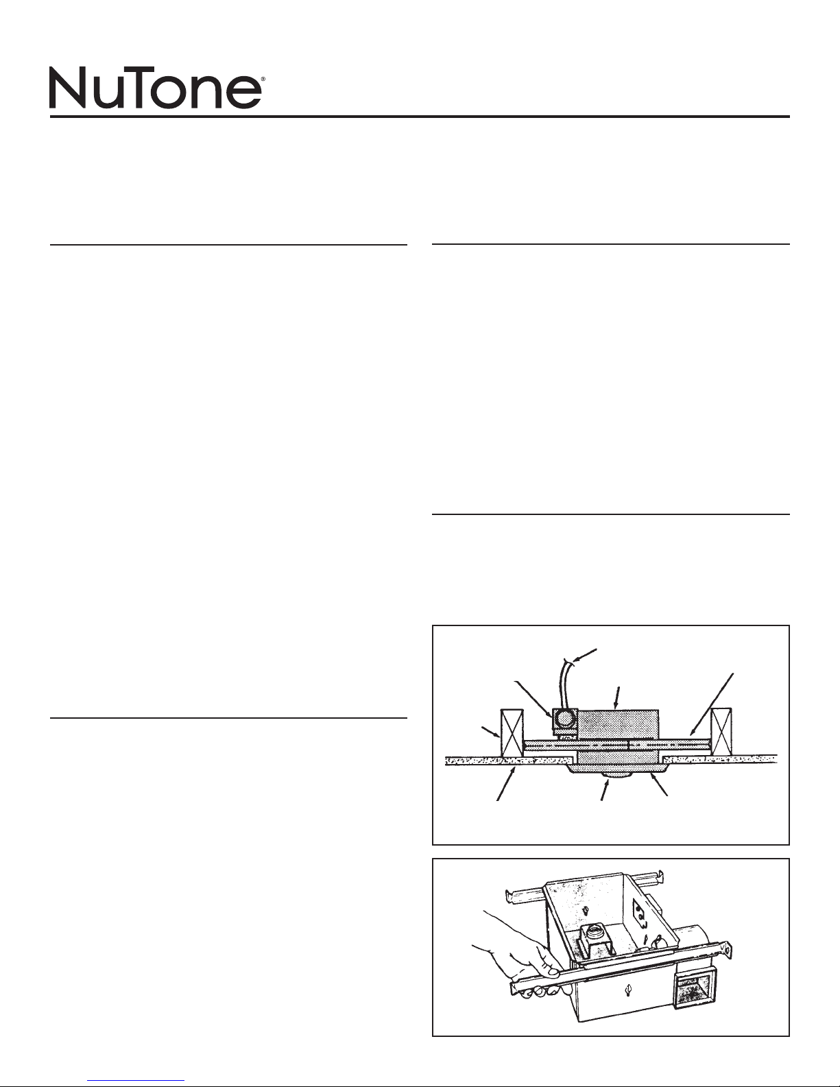
Refer to FIGURE 1
Follow these basic steps when installing this unit:
1. Nail unit to joists.
2. Attach ductwork (Models 9417DN or 9427P only).
3. Connect power cable.
4. Fasten grille to housing.
PREPARE THE HEATER
1. Remove the unit from carton. Save carton for use as plaster
shield in rough-in installations.
Refer to FIGURE 2
2. Slide adjustable mounting brackets into bracket channels on
housing.
DAMPER/DUCT
CONNECTOR
POWER CABLE
HOUSING
MOUNTING
BRACKET
CAUTION
1. For general ventilating use only. Do not use to exhaust hazard-
ous or explosive materials and vapors.
2. This product is designed for installation in flat ceilings only. DO
NOT MOUNT THIS PRODUCT IN A WALL.
3. To avoid motor bearing damage and noisy and/or unbalanced
impellers, keep drywall spray, construction dust, etc. off power
unit.
4. Please read specification label on product for further information
and requirements.
CEILING
JOIST
CEILING MATERIAL BULB(S)
GRILLE
FIGURE 1
FIGURE 2
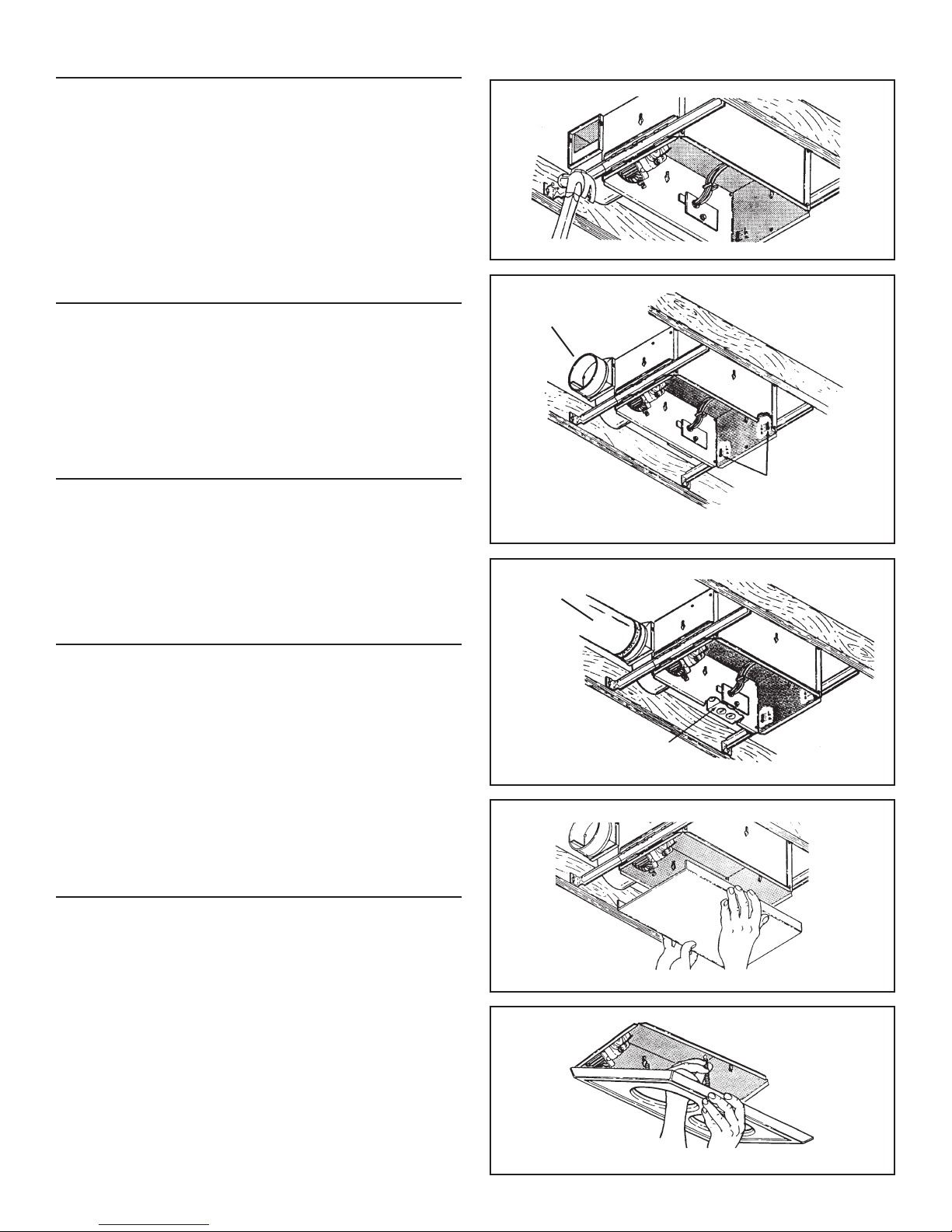
INSTALL THE HEATER
Refer to FIGURE 3
1. Position unit between joists and extend mounting brackets.
2. Nail brackets firmly to joists. Bottom of brackets should be positioned flush with joist bottom.
Refer to FIGURE 4
3. Brackets are factory-set for ½” thick ceiling material. For thicker
ceilings, loosen 4 vertical adjusting screws and lower housing
to appropriate thickness on gauges. Tighten vertical adjusting
screws firmly.
ATTACH DUCTWORK
(MODELS 9417DN & 9427P ONLY)
Refer to FIGURE 4
1. Snap the damper/duct connector onto housing. Make sure that
tabs on the connector lock in housing slots and that gravity
closes damper.
2. Attach 4” round duct to damper/duct connector and run ductwork
to the outside through a roof or wall cap. Check damper to make
sure it opens freely. Tape all joints to make them secure and air
tight.
WIRE THE HEATER
Refer to FIGURE 5
1. Remove wiring box from side of housing. Remove knockout(s)
and connect power cable(s) to wiring box using proper U.L. approved connector.
Refer to FIGURE 6 (on page 3)
2. Wire unit as indicated in appropriate diagram. Push all wiring
into wiring box and replace wiring box onto housing.
FIGURE 3
DAMPER/DUCT
CONNECTOR
VERTICAL ADJUSTING
SCREWS
FIGURE 4
4” ROUND
DUCT
FINAL ASSEMBLY
Refer to FIGURE 7
1. Protect motor, bulb sockets and wiring from construction dust,
drywall spray, paint, etc. by using the plaster shield. Cut it from
the carton and follow directions printed on it.
2. Finish all ceiling work as necessary.
3. Remove plaster shield and check if bottom of housing is flush
with finished ceiling. If not, loosen vertical adjusting screws,
reposition housing, and retighten screws.
Refer to FIGURE 8
4. Attach grille by hooking springs onto clips on side of housing.
5. Install BR40 or R40-size 250W infrared bulb(s). Center grille
around bulb(s).
USE AND CARE
MODELS 9417DN & 9427P OPERATION NOTE: These units are
designed with a thermostat which senses excess heat and may start
the blower automatically. This is normal and is no cause for concern.
DISCONNECT ELECTRIC POWER SUPPLY AND LOCK OUT
SERVICE PANEL BEFORE CLEANING OR SERVICING THIS UNIT.
To clean fan assembly: Remove bulb(s). Unhook springs and
remove grille. Loosen motor assembly mounting screws and rotate
assembly to remove it from housing. Gently vacuum fan, motor and
interior of housing. Reverse steps to replace fan assembly.
To clean grille assembly: Remove bulb(s). Unhook springs and
remove grille. Clean grille with mild soapy water. Use a mild detergent, such as dishwashing liquid. Dry with a soft cloth. DO NOT
USE ABRASIVE CLOTHS, STEEL WOOL PADS OR SCOURING
POWDERS.
Motor is permanently lubricated —Do not oil or disassemble motor.
WIRING BOX
FIGURE 5
FIGURE 7
FIGURE 8
2
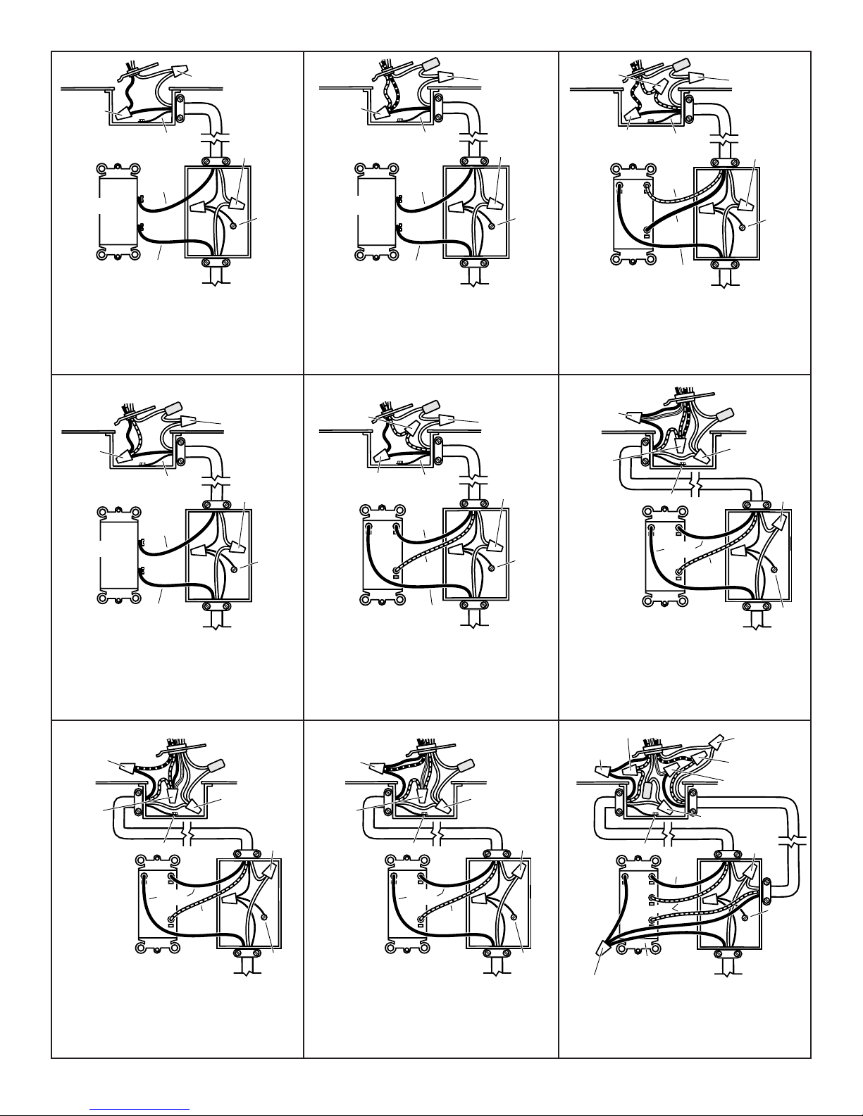
MODEL 9412D MODEL 9417DN
120 VAC LINE IN
GROUND
BLACK
BLACK
WHITE to
WHITE
WHITE to WHITE
GROUND
BLACK to
BLACK
SWITCH OR TIMER
WHITE to
WHITE / GRAY
120 VAC LINE IN
GROUND
BLACK
BLACK
WHITE
to WHITE
BLACK to
RED & BLUE
GROUND
SWITCH OR TIMER
RED
VENT
WHITE to
WHITE / GRAY
120 VAC LINE IN
BLACK
BLACK
WHITE to
WHITE
BLACK TO BLUE
RED TO RED
GROUND
HEAT
DUAL CONTROL
GROUND
WHITE to
WHITE / GRAY
120 VAC LINE IN
GROUND
BLACK
BLACK
WHITE to
WHITE
BLACK to
BLACK
& RED
GROUND
SWITCH OR TIMER
WHITE to
WHITE / GRAY
120 VAC LINE IN
GROUND
BLACK
BLACK
LIGHT
BLACK to BLACK
GROUND
HEAT
RED
DUAL CONTROL
RED to RED
WHITE to
WHITE
120 VAC LINE IN
GROUND
LIGHT
DUAL CONTROL
3 WHITE / GRAY WIRES
VENT & HEAT
BLACK to BLACK,
& YELLOW
RED to RED
& BLUE
GROUND
RED
WHITE to
WHITE
BLACK
120 VAC LINE IN
GROUND
LIGHT
& VENT
DUAL CONTROL
3 WHITE / GRAY WIRES
HEAT
BLACK to
BLACK, & BLUE
RED to RED
& YELLOW
GROUND
RED
WHITE to
WHITE
BLACK
120 VAC LINE IN
GROUND
VENT
DUAL CONTROL
3 WHITE / GRAY WIRES
HEAT & LIGHT
BLACK to
BLUE
RED to RED,
BLACK &
YELLOW
GROUND
RED
WHITE to
WHITE
BLACK
HEAT
120 VAC LINE IN
GROUND
3 BLACK WIRES
3 WHITE
WIRES
LIGHT
BLACK
3-FUNCTION CONTROL
WHITE to WHITE / GRAY
VENT
BLACK to BLACK
BLACK to YELLOW
RED to RED
RED
GROUND
WHITE to WHITE
RED to BLUE
Lamp & Vent operate together
MODEL 9417DN
Lamp & Vent operate separately
MODEL 9422P
Lamps operate together
MODEL 9427P
Lamps operate together –
Vent separately
MODEL 9422P
Lamps operate separately
MODEL 9427P
Light & Vent operate together –
Heat separately
3 FIGURE 6
MODEL 9427P
Vent & Heat operate together –
Light separately
MODEL 9427P
Light, Vent & Heat operate separately
 Loading...