

NuTone 9093WH DELUXE HEAT-A-VENTLITE Installation Instructions Manual
MODEL 9093WH
MODEL 9093WH
Page 1
DELUXE HEAT-A-VENTLITE
®
READ AND SAVE THESE INSTRUC
WARNING
TO REDUCE THE RISK OF FIRE, ELECTRIC SHOCK, OR
INJURY TO PERSONS, OBSERVE THE FOLLOWING:
1. Use this unit only in the manner intended by the manufacturer.
If you have questions, contact the manufacturer at the
address or telephone number listed in the warranty.
2. Before servicing or cleaning unit, switch power off at service
panel and lock the service disconnecting means to prevent
power from being switched on accidentally. When the
service disconnecting means cannot be locked, securely
fasten a prominent warning device, such as a tag, to the
service panel.
3. Installation work and electrical wiring must be done by a
qualified person(s) in accordance with all applicable codes
and standards, including fire-rated construction codes
and standards.
4. Sufficient air is needed for proper combustion and
exhausting of gases through the flue (chimney) of fuel
burning equipment to prevent backdrafting. Follow the
heating equipment manufacturer’s guideline and safety
standards such as those published by the National Fire
Protection Association (NFPA), and the American Society
for Heating, Refrigeration and Air Conditioning Engineers
(ASHRAE), and the local code authorities.
5. When cutting or drilling into wall or ceiling, do not damage
electrical wiring and other hidden utilities.
6. Ducted fans must always be vented to the outdoors.
7. IMPORTANT: DO NOT MOUNT OVER TUB OR IN
SHOWER STALL ENCLOSURE.
8. This unit must be grounded.
INSTALLATION PREPARATION
1. Remove complete assembly from carton. Loosen screws
holding grille and remove the grille.
2. Loosen power unit mounting screws and remove power unit
from rough-in housing.
3. Remove tape from back draft damper and be certain the
damper opens and closes freely.
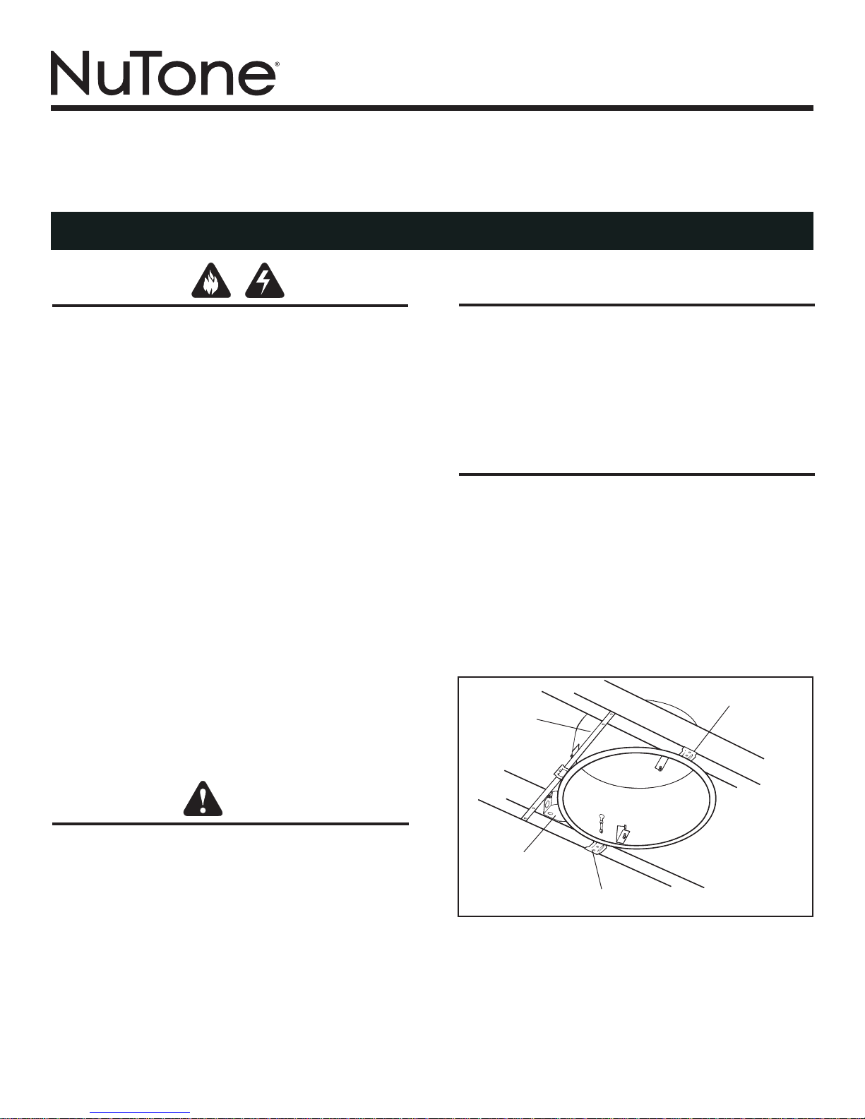
MOUNTING TO OPEN JOISTS
Refer to Figure 1.
1. Insert hanger bar on mounting bracket opposite discharge
opening and mount rough-in housing to ceiling joists at
desired location.
2. Install mounting brackets into slots in housing and adjust
housing so flange will be flush to proposed finished ceiling
line. Tighten screws securely.
3. Attach 4” round duct and vent to outside through wall
or ceiling.
4. Remove junction box cover and desired knockout from
junction box in housing.
ADJUSTABLE
HANGER
BAR
TIONS
NAILING BRACKET
CAUTION
1. For general ventilating use only. Do not use to exhaust
hazardous or explosive materials and vapors.
This product is designed for installation in ceilings up to a 12/12 pitch
2.
(45 degree angle). Duct connector must point up.
3. To avoid motor bearing damage and noisy and/or
unbalanced
off power unit.
4. The flange of the rough-in housing MUST be flush with
the finished plaster or drywall surface to assure proper
and safe operation.
5. The switch (furnished) should be used and wired in
accordance with the wiring diagram.
6. Please read specification label on product for further
information and requirements.
impellers, keep drywall spray, construction dust, etc.
HEATER
OUTLET BOX
NAILING BRACKET
FIGURE 1
HEATER
JUNCTION
BOX
YELLOW
BLUE
BLACK
RED
HOUSE
WIRING
SWITCH BOX
(REAR VIEW)
HOUSE
WIRING
120vAC
LINE
TO HOUSE
PANEL BOARD
BLACK
WHITE
GROUND
VENT
LIGHT
HEAT
NIGHT
LIGHT
T
WHITE
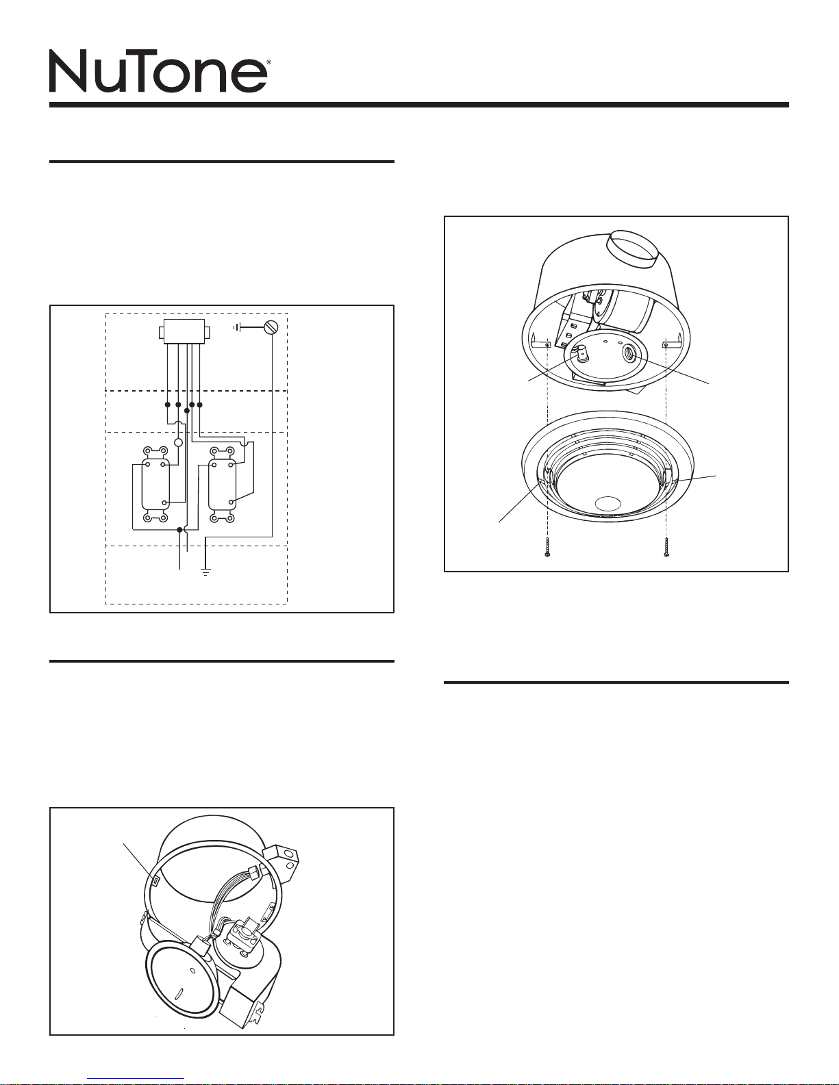
WIRING
Refer to Figure 2.
1. Run five (5) wires and ground of 12 gauge from heater’s
junction box to wall switch.
2. The switch installs in a double-gang outlet box. When a
thermostat or timer is used, connect at point marked “T”.
3. Replace junction box cover in heater housing when wiring
is complete.
MODEL 9093WH
Page 2
Refer to Figure 4.
4. Install 100 watt bulb and 7 watt lamp for night light.
5. Mount grille and lens assembly over mounting screws in
housing. Tighten securely.
COMPLETING INSTALLATION
Refer to Figure 3.
1. Insert hooked hinge on power unit to hanger bracket in
rough-in housing.
2. Swing fan and heater unit into place over mounting bracket
screws and tighten securely.
3. Plug in fan and heater assembly to receptacle in junction
box cover.
SLOTTED
HANGER BRACKET
FIGURE 2
FIGURE 3
NIGHT LIGHT
RECEPTACLE
KEY-HOLE
SLOT
LIGHT
RECEPTACLE
KEY-HOLE
SLOT
FIGURE 4
INSTALLATING IN EXISTING
CONSTRUCTION
1. Review “WIRING” section of these instructions.
2. Drill a small hole in ceiling in proposed location (locate
this hole in attic or crawl space).
3. In attic, mark ceiling for cutout by using the housing as
a template. Mark around outside of plaster flange. Make
cutout along this line.
4. Connect wires from switch to heater before mounting
the housing.
5. Install a header between ceiling joists and nail housing to one
joist and header.
NOTE: The two (2) hanger bars (separate pieces) and two
mounting brackets (on the housing) are not needed for this
type of installation.
6. Install ductwork.
7. Install power unit, light bulbs and grille/lens assembly. Refer
to “COMPLETING INSTALLATION”.
NOTE: Please refer to your NuTone catalog for a complete
listing of optional accessory items.
 Loading...