

Page 1
Bathroom Ventilator
MODELS: 8832WH, 8832SA & 8833
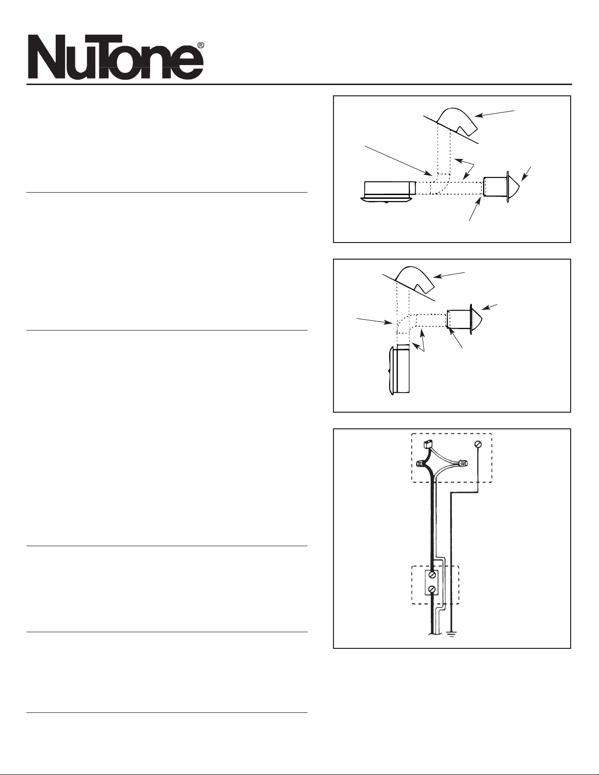
FIGURE 1
ADJUSTABLE
ELBOW
• Do not mount over tub or in shower stall enclosure.
• Not for use in kitchens.
IMPORTANT SAFETY INSTRUCTIONS
WARNING: TO REDUCE THE RISK OF FIRE. ELECTRIC SHOCK, OR
INJURY TO PERSONS, OBSERVE THE FOLLOWING:
A. Use this unit only in the manner intended by the manufacturer.
If you have questions, contact the manufacturer.
B. Before servicing or cleaning unit, switch power off at service panel and lock
service panel to prevent power from being switched on accidentally.
When the service disconnecting means cannot be locked, securely
fasten a prominent warning device, such as a tag, to the service panel.
CAUTION:
For general ventilating use only. Do not use to exhaust hazardous or
explosive materials and vapors.
INSTALLATION INSTRUCTIONS
WARNING: TO REDUCE THE RISK OF FIRE, ELECTRIC SHOCK, OR
INJURY TO PERSONS, OBSERVE THE FOLLOWING:
A. Installation work and electrical wiring must be done by
qualified person(s) in accordance with all applicable codes
and standards, including fire-rated construction.
B. Sufficient air is needed for proper combustion and exhausting of gases
through the flue (chimney) of fuel burning equipment to prevent back
drafting. Follow the heating equipment manufacturer's guideline and safety
standards such as those published by the National Fire Protection
Association (NFPA),and the American Society for Heating, Refrigeration
and Air Conditioning Engineers (ASHRAE), and the local code authorities.
C. When cutting or drilling into wall or ceiling, do not damage
electrical wiring and other hidden utilities.
D. Ducted fans must always be vented to the outdoors.
E. If this unit is to be installed over a tub or shower, it must
be marked as appropriate for the application.
F. NEVER place a switch where it can be reached from
a tub or shower.
G.
Do not use this fan with any solid-state speed control device.
FOR BEST RESULTS
When installing the ventilator in a new construction site, install
the housing during the rough-in construction of the house. Blower
and grille should be installed after finished ceiling is in place.
To install the ventilator in an existing house requires accessible
area above the proposed installation location (attic or crawl space).
The housing must be installed to a finished ceiling from above.
LOCATION
The ventilator is intended for installation in bathroom or laundry.
CAUTION: Do not install the unit over a tub or in a shower
stall enclosure.
ROOF
CAP
WALL
CAP
IN CEILING
TRANSITION
FURNISHED
WITH WALL CAP
3"
ROUND
DUCT
FIGURE 2
ADJUSTABLE
ELBOW
ROOF
CAP
WALL
CAP
IN WALL
TRANSITION
FURNISHED
WITH WALL CAP
3"
ROUND
DUCT
FIGURE 3
STANDARD
WALL
SWITCH
GREEN
GROUND
SCREW
SWITCH
BOX
JUNCTION
BOX
EARTH
GROUND
120vAC, 60Hz
HOUSE POWER
INSTALLATION INSTRUCTIONS
READ & SAVE THESE INSTRUCTIONS!
INSTALLATION IN A NEW
CONSTRUCTION SITE
1. Remove the blower unit from the housing by unplugging it then loosening
the three mounting screws and rotating the unit to free it from the screws.
2. Loosely attach housing to ceiling joists through keyhole slots
in mounting brackets. Keyhole slots in brackets are provided
to allow for adjustment to various ceiling thicknesses. Adjust
housing so bottom is flush to proposed finished plaster line,
then securely fasten housing to joists.
Page 2
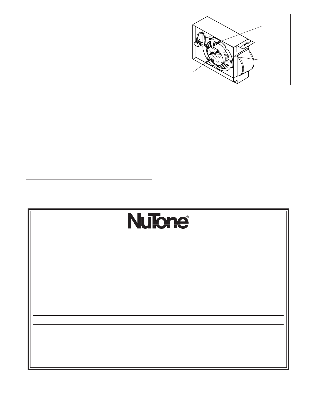
FIGURE 4
BLOWER
MOUNTING
STUD
MOUNTING
SCREWS (3)
Product specifications subject to change without notice. 4820 Red Bank Road, Cincinnati, Ohio 45227
Printed in U.S.A., Rev. 01/2004, Part No. 84762
INSTALLATION IN A NEW
CONSTRUCTION SITE (continued)
3. Snap duct adapter over flanges on housing. Run 3" round
duct from housing to wall or roof cap.
Refer to Figures Figures 1 and 2.
IMPORTANT: Be sure nothing obstructs the discharge
of the fan. Take precautions to assure that insulation
does not get into ductwork or fan discharge opening.
4. Refer to Figure 3. Run 120vAC, 60Hz power wiring from
wall switch to ventilator housing. Remove the housing
junction box cover and connect wires from wall switch to
receptacle wires, using wire connectors - white to white,
black to black. Use a box connector on junction box.
Connect earth ground to green screw in junction box.
Replace junction box cover.
CAUTION: Be sure all wiring complies with local
electrical codes and housing is properly grounded.
5. Refer to Figure 4. Insert blower unit into housing, with stud
on mounting bracket on the side near the receptacle. Turn
bracket clockwise to lock blower into position, then tighten
the three screws. Plug in motor.
6. MODEL 8832NA: Compress spring clips on grille and isert
into slots provided in housing. Push grille up flush to ceiling.
MODEL 8833NA: Place hole in center of grille bezel over
stud on motor plate and fasten with nut provided. Snap
grille panel over the four (4) spring clips on grille bezel.
INSTALLATION IN EXISTING
CONSTRUCTION
To install the ventilator in an existing home requires
accessible area above the proposed installation location (attic
or crawl space). Because of the size and shape of the
ventilator housing it must be installed to a finished ceiling from
above.
Installation Hints
1. Review the section: INSTALLATION IN NEW
CONSTRUCTION SITE and follow all instructions where
applicable for your installation.
2. Refer to Figures 1 and 2 for duct work and Figure 3 for
wiring.
3. Drill small hole in ceiling in proposed location, then locate
this hole in attic or crawl space).
4. In attic, position housing over drilled hole and against ceiling
joist, being sure to have duct collar in the direction of the
ductwork. Mark ceiling for cutout by using housing as a
template - mark along the plaster flange. make cutout on
this outline.
5. Connect wires to receptacle wires in housing before
mounting.
6. Mount housing to ceiling joist.
One Year Limited Warranty
WARRANTY OWNER: NuTone warrants to the original consumer purchaser of its products that such products will be free from defects in materials or workmanship for a period
of one (1) year from the date of original purchase. THERE ARE NO OTHER WARRANTIES, EXPRESS OR IMPLIED, INCLUDING, BUT NOT LIMITED TO, IMPLIED
WARRANTIES OF MERCHANTABILITY OR FITNESS FOR A PARTICULAR PURPOSE.
During this one year period, NuTone will, at its option, repair or replace, without charge, any product or part which is found to be defective under normal use and service.
THIS WARRANTY DOES NOT EXTEND TO FLUORESCENT LAMP STARTERS OR TUBES, FILTERS, DUCT, ROOF CAPS, WALL CAPS AND OTHER ACCESSORIES
FOR DUCTING. This warranty does not cover (a) normal maintenance and service or (b) any products or parts which have been subject to misuse, negligence, accident,
improper maintenance or repair (other than by NuTone), faulty installation or installation contrary to recommended installation instructions.
The duration of any implied warranty is limited to the one year period as specified for the express warranty. Some states do not allow limitation on how long an implied warranty
lasts, so the above limitation may not apply to you.
NUTONE’S OBLIGATION TO REPAIR OR REPLACE, AT NUTONE’S OPTION, SHALL BE THE PURCHASER’S SOLE AND EXCLUSIVE REMEDY UNDER THIS
WARRANTY. NUTONE SHALL NOT BE LIABLE FOR INCIDENTAL, CONSEQUENTIAL OR SPECIAL DAMAGES ARISING OUT OF OR IN CONNECTION WITH
PRODUCT USE OR PERFORMANCE. Some states do not allow the exclusion or limitation of incidental or consequential damages, so the above limitation or exclusion may
not apply to you. This warranty gives you specific legal rights, and you may also have other rights, which vary from state to state. This warranty supersedes all prior warranties.
WARRANTY SERVICE: To qualify for warranty service, you must (a) notify NuTone at the address stated below or telephone 1/800-543-8687, (b) give the model
number and part identification and (c) describe the nature of any defect in the product or part. At the time of requesting warranty service, you must present
evidence of the original purchase date.
Date of Installation Builder or Installer
Model No. and Product Description
IF YOU NEED ASSISTANCE OR SERVICE:
For the location of your nearest NuTone Independent Authorized Service Center:
Residents of the contiguous United States Dial Free 1-800-543-8687
Please be prepared to provide:
Product model number • Date and Proof of purchase • The nature of the difficulty
Residents of Alaska or Hawaii should write to: NuTone Inc. Attn: Department of National Field Service, 4820 Red Bank Road, Cincinnati Ohio 45227-1599.
Residents of Canada should write to: Broan-NuTone Canada, 1140 Tristar Drive, Mississauga, Ontario, Canada L5T 1H9.
Rev. 03/2001
Page 3

Ventilateur de salle de bain
MODELES: 8832WH, 8832SA et 8833
FIGURE 1
COUDE
REGLABLE
• Ne pas installer au-dessus du bain ni de la douche.
• Ne pas installer dans la cuisine.
IMPORTANT SAFETY INSTRUCTIONS
WARNING – TO REDUCE THE RISK OF FIRE, ELECTRIC SHOCK, OR
INJURY TO PERSONS, OBSERVE THE FOLLOWING:
A. Use this unit only in the manner intended by the manufacturer.
If you have questions, contact the manufacturer.
B. Before servicing or cleaning unit, switch power off at Service Panel and lock
Service Panel to prevent power from being switched on accidentally.
When the service disconnecting means cannot be locked, securely fasten a
prominent warning device, such as a tag, to the service panel.
CAUTION:
For general ventilating use only. Do not use to exhaust hazardous or explosive
materials and vapors.
INSTALLATION INSTRUCTIONS
WARNING – TO REDUCE THE RISK OF FIRE, ELECTRIC SHOCK, OR
INJURY TO PERSONS, OBSERVE THE FOLLOWING:
A. Installation work and electrical wiring must be done by qualified person(s) in
accordance with all applicable codes and standards, including fire-rated
construction.
B. Sufficient air is needed for proper combustion and exhausting of gases through
the flue (chimney) of fuel burning equipment to prevent back drafting. Follow the
heating equipment manufacturer's guideline and safety standards such as those
published by the National Fire Protection Association (NFPA),
and the American Society for Heating, Refrigeration and Air Conditioning
Engineers (ASHRAE), and the local code authorities.
C. When cutting or drilling into wall or ceiling, do not damage electrical wiring and
other hidden utilities.
D. Ducted fans must always be vented to the outdoors.
E. If this unit is to be installed over a tub or shower, it must be marked as
appropriate for the application.
F. NEVER place a switch where it can be reached from a tub or shower.
G. Ne pas utiliser ce ventilateur vec des variatures de vitesse à semi-conducteurs.
POUR DE MEILLEURS RESULTATS
Lorsque le ventilateur est installé dans une malson neuve, installer le
boîtier au moment de la pose de la structure.
Le ventilateur et la grille doivent être mis en place une fois la finition terminée.
Pour installer le ventilateur dans une maison existante, il faut qu’un
espace suffisant soit aménagé au-dessus de l’endroit où sera placé l’appareil
(faux-plafond ou grenier). Le boîtier doit être installé dans un plafond fini, à
partir d’un endroit situé au-dessus de ce dernier.
EMPLACEMENT
Ce ventilateur est conçu pour être installé dans une salle de bain ou une
salle de lavage.
ATTENTION: Ne pas installer l’appareil au-dessus du bain ni de la
douche.
INSTALLATION DANS UNE MAISON NEUVE
1. Retirer le ventilateur du boîtier in le débranchant, puis en retirant les trois
vis de fixation; faire tourner le ventilateur pour le sortir du boîtier.
2. Fixer le boîtier à la structure de plafond en plaçant des vis dans les orifices
de montage des côtés. Ces orifices sont conçus pour que le boîtier s’ajuste
à differentes épalsseurs de plafond. Ajuster le boîtier de façon que le
rebord soit à égalité avec le futur plafond fini, puis le fixer solidement en
place.
3. Fixer l’adaptateur de conduit à la sortie du boîtier. Installer un conduit rond
de 3 po entre le boîtier et la sortie sur le toit ou la sortie murale.
Voir les Figures 2 et 3.
IMPORTANT: S’assurer qu’aucun obstacle ne se trouve devant la
sortie du ventilateur. Faire bien attention que l’isolant ne vienne
obstruer le conduit ou la sortie du ventilateur.
SORTIE SUR
LE TOIT
SORTIE
MURALE
PLAFOND
RACCORD FOURNI
AVEC LA SORTIE
MURALE
TUYAU
ROND
DE 3 PO
FIGURE 2
COUDE
REGLABLE
SORTIE SUR
LE TOIT
SORTIE
MURALE
MUR
RACCORD FOURNI
AVEC LA SORTIE
MURALE
TUYAU
ROND
DE 3 PO
FIGURE 3
INTERRUPTEUR
STANDARD
VIS SERTE
DE MISE A
LA TERRE
BOITE DE
L’INTERRUPTEUR
BOITE DE
RACCORDEMENT
MISE A LA
TERRE
COURANT
120 V c.a., 60Hz
DIRECTIVES D’INSTALLATION
LIRE ET CONSERVER CES DIRECTIVES!
4. Voir la Figure 3. Installer du fil 120 V c.a., 60 Hz entre
l’interrupteur mural et le boîtier du ventilateur. Retirer le
couvercle de la boîte de reccordement du boîtier et raccorder
les fils à l’aide de connecteurs – blanc avec et noir aves noir.
Raccorder le fil de mise à la terre à la vis verte de la boîte de
raccordement. Replacer le couvercle de la boîte.
ATTENTION: S’assurer que les fils sont conformes aux
normes en vigueur et que la boîtier est bien mis à la terre.
Page 4

FIGURE 4
VENTILATEUR
BRIDE DE
FIXATION
VIS DE
FIXATION
Les caractéristiques peuvent être modifiées sans préavis.
4820 Red Bank Road, Cincinnati, Ohio 45227
Imprimé aux E.-U.
INSTALLATION DANS
UNE MAISON NEUVE (suite)
5. Voir la Figure 4. Insérer le ventilateur dans le boîtier, le
montant de la bride de fixation du côté de la prise de courant.
Tourner la bride dans le sens horaire pour verrouiller la
ventilateur en place, puis fixer les trois vis de retenue.
Brancher le moteur.
6. MODELE 8832NA: Appuyer sur les broches à ressors de la
grille et les glisser dans les orifices du boîtier. Pousser sur la
grille jusqu’au plafond.
MODELE 8832NASA: Placer l’orifice au centre de la grille
vis-à-vis le montant de la bride de fixation et fixer la grille en
place à l’aide de l’écrou fourni.
MODELE 8833NA: Placer l’orifice au centre de la plaque de
la grille vis-à-vis le montant de la bride fixation et la fixer avec
l’écrou fourni. Insérer la grille en la fixant sur les quatre (4)
cliquets à ressort de la plaque.
INSTALLATION DANS UNE MAISON
EXISTANTE
Pour installer le ventilateur dans une maison existante, il faut
qu’un espace suffisant soit aménagé au-dessus de l’endroit où
sera placé l’appareil (faux-plafond ou grenier). En raison de la
taille du ventilateur, le boîtier doit être installé dans un plafond
fini, à partir d’un endroit situé au dressus de ce dernier.
Trucs d’installation
1. Revoir la section INSTALLATION DANS UNE MAISON
NEUVE et suivre les directives qui s’appliquent à votre situation.
2. Voir les Figures 1 et 2 pour l’installation du conduit et la
Figure 3 pour la mise en place du fil électrique.
3. Percer de petits trous dans le plafond à l’endroit où sera installé
le ventilateur; localiser ensuite ces petits trous dans le grenier
ou le faux-plafond.
4. Dans le grenier, placer le boîtier sur les petits trous, contre un
montant du plafond, en s’assurant que la bride de sortie se
trouve bien en direction du conduit. Marquer le plafond en vous
servant du boîtier comme modèle, le long du montant, puis
percer l’orifice.
5. Raccorder les fils d’allimentation aux de la boîte de
raccordement.
6. Fixer le boîtier au montant du plafond.
Garantie limitée d’un an
GARANTIE DU PROPRIÉTAIRE: NuTone garantie à l'acheteur original de ses produits que ces derniers seront exempts de tout défaut de matériaux et de fabrication pour une période
d’un (1) an à compter de la date d'achat. AUCUNE AUTRE GARANTIE, IMPLICITE OU EXPRESSE, N'EST DONNÉE, Y COMPRIS, MAIS SANS S'Y LIMITER, GARANTIE DE
MARCHANDIBILITÉ OU D'ADAPTATION À UN USAGE PARTICULIER.
Pendant cette période d’un an, NuTone procédera au remplacement ou à la réparation sans aucuns frais, mais à sa propre discrétion, de tout produit ou pièce jugé défectueux dans
le cadre d'une utilisation normale. CETTE GARANTIE NE VISE PAS LES DISPOSITIFS D'AMORÇAGE NI LES TUBES DES LUMINAIRES FLUORESCENTS. Cette garantie ne
couvre pas (a) l'entretien et le service courants ni (b) les produits et les pièces ayant fait l'objet d'un usage abusif, de négligence, d'un accident, d'un entretien ou d'une réparation non
appropriée (par du personnel non autorisé par NuTone), d'une mauvaise installation ou d'une installation non conforme aux directives d'installation fournies.
La durée de toute garantie implicite est limitée à la période de deux ans précisée pour la garantie expresse. Certains états ne reconnaissent pas les restrictions relatives à la durée des
garanties implicites; il se pourrait donc que cette restriction ne s'applique pas dans votre cas.
LE REMPLACEMENT OU LA RÉPARATION PAR NUTONE, À SA PROPRE DISCRÉTION, DE TOUT PRODUIT OU PIÈCE DÉFECTUEUX CONSTITUE LE SEUL REMÈDE DE
L'ACHETEUR EN VERTU DE CETTE GARANTIE. NUTONE NE PEUT ÊTRE TENUE RESPONSABLE DES DOMMAGES INDIRECTS, CONSÉCUTIFS OU SPÉCIAUX
ATTRIBUABLES À L'UTILISATION OU AU RENDEMENT DU PRODUIT. Certains états ne reconnaissent pas les restrictions ni les exclusions relatives aux dommages indirects,
consécutifs ou spéciaux; il se pourrait donc que cette restriction ne s'applique pas dans votre cas. La présente garantie vous accorde des droits spécifiques, mais vous pourriez aussi
avoir d'autres droits en fonction de l'état dans lequel vous résidez. Cette garantie remplace toute autre garantie donnée précédemment.
SERVICE SOUS GARANTIE Pour être admissible au service sous garantie, vous devez (a) aviser NuTone, à l'adresse fournie ci-dessous ou par téléphone au 1 800 5433687, (b) fournir le numéro du modèle et la description de la pièce et (c) décrire la nature du défaut de la pièce ou du produit. Au moment de la demande de service sous
garantie, vous devez fournir une preuve de la date d'achat originale.
Date d’installation Entrepreneur ou installateur
N° de modèle et description du produit
POUR OBTENIR DE L’ASSISTANCE OU DU SERVICE:
Pour connaître le Centre de service NuTone autorisé indépendant le plus proche:
Résidents des États-Unis continentaux, composez le numéro sans frais: 1 800 543 8687
Garder à protée de la main le numéro du modèle, la date et la preuve d’achat, le type de problème.
Résidents de l’Alaska et d’Hawaii: Écrivez à NuTone Inc. Attn: Department of National Field Service, 4820 Red Bank Road, Cincinnati Ohio USA 45227-1599.
Résidents du Canada: Écrivez à Broan-NuTone Canada, 1140 Tristar Drive, Mississauga, Ontario Canada L5T 1H9.
Rev. 03/2001
 Loading...