

Page 1
INSTALLATION INSTRUCTIONS
READ & SAVE THESE INSTRUCTIONS!
Heat-A-Ventlite
®
Combination
MODEL: 665RF
TYPE IC suitable for use under thermal insulation
LOCATION
1. Mount heater to ceiling joists, or if necessary, to a header
installed between joists.
2. Caution: Do not mount heater closer than 12" to a
vertical surface. Do not mount over tub or in shower
enclosure.
3. Installation in existing construction requires an accessible
area above the desired location. Make sure that wiring can
be run to the location.
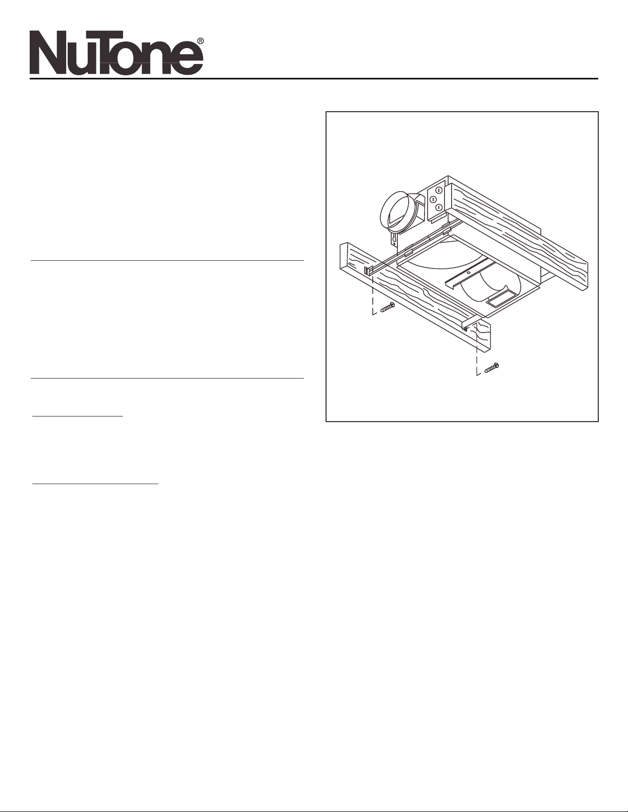
MOUNTING HEATER HOUSING
NEW CONSTRUCTION
FIGURE 1
Using Hanger Bars
Refer to Figure 1.
1. Insert hanger bars in slots provided in housing.
2. Locate heater housing between joists so that bottom of heater housing is even with the planned finished ceiling.
3. Use screws or nails (not provided) to secure hanger bars to ceiling joists.
Using Side Mounting Tabs
1. Locate heater housing next to ceiling joist.
2. Use wood screws (not provided) through keyhole slots in mounting tabs to loosely attach housing to ceiling joist.
3. Adjust housing so that it will be flush with the finished ceiling. When housing is properly adjusted, tighten screw in slots to
secure housing.
EXISTING CONSTRUCTION
1. Determine desired location for heater.
2. Drill a small hole through the ceiling at the desired location and stick a coat hanger or stiff wire through hole into attic to help
find the location from above.
3. Check the area above to make sure that wiring can be installed and that the installation will not interfere with existing
electrical wiring.
4. From above, place the housing between ceiling joists at the desired location. Using the housing as a template, mark the area
to be cut out along the bottom flange of the housing.
5. After making the cutout, install the housing in the opening using the hanger bars or mounting tabs as described above. Make
sure that the bottom of the housing is flush with the bottom of the finished ceiling.
Page 2
HEATER JUNCTION BOX
LIGHT
RECEPTACLE
WHITE
WHITE
RED
GREEN
WALL SWITCH BOX
WHITE
BLACK
120VAC LINE
SUPPLY
GROUND
LIGHT
HEAT
VENT
WHITE
BLACK
BLUE
VENT
RECEPTACLE
HEAT
RECEPTACLE
(WHITE)
FIGURE 2
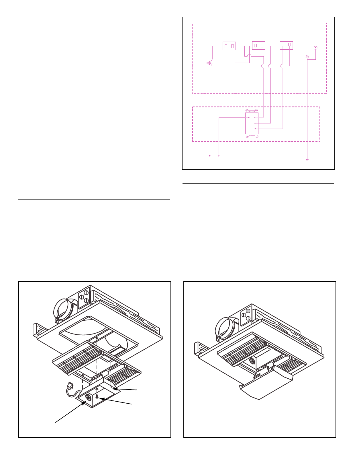
WIRING
All wiring must comply with local and national codes
and unit must be properly grounded.
1. Run 120VAC, 60Hz supply wiring to the wall switch (not
provided). The unit must be wired on a separate 20
Amp circuit.
2. Run wiring from the switch to the housing junction box.
Loosen screw holding exterior wiring compartment cover
and remove cover. Interior wiring compartment may be
removed if necessary by loosening screw in keyhole slot in
cover. Remove knockout(s) as required and install
approved box connector.
3. Refer to fig. 2. Connect white wires in junction box to
white (neutral) supply wire. Connect the blue wire in the
junction box to the supply wire from the vent switch.
Connect the black wire to the supply wire from the light
switch. Connect the red wire in the junction box to the
supply wire from the heat switch. Connect green ground
lead in the junction box to the supply ground.
4. Replace wiring compartment cover and tighten screw to
secure.
5. Insert vent motor plug in vent receptacle on wiring
compartment cover. Insert plug from heater assembly into
the white socket of the wiring compartment cover.
DUCTING
1. Snap plastic duct adapter and damper assembly over
flanged opening on housing. Connect 4" round duct to the
duct adapter and secure with duct tape. The duct should
be run to the outside of the structure through the roof or
wall cap. For maximum performance keep duct runs as
short and as straight as possible.
FIGURE 3
FIGURE 4
LIGHT SOCKET
REFLECTOR
LENS
REFLECTOR
MOUNTING
SCREW
USE COMPACT FLUORESCENT
LAMP, NEMA TYPE
CFQ13W/GX23/827 (PURCHASE
LOCALLY)
MOUNTING REFLECTOR AND GRILLE
1. Place reflector in the opening in the center of the grille.
The notches in the reflector should fit over the pegs on
either side of the opening. Insert plug from lamp ballast
into lamp receptacle on wiring compartment.
2. Place 1" screw, provided, through the center hole in the
reflector and thread it into the hole in the mounting bracket
running across the housing. Tighten the screw just
enough to hold the grille firmly against the ceiling.
3. Install a 13 watt Compact Fluorescent lamp, NEMA type
CFQ13W/GX23/827. (Not provided)
4. Snap lens into position in center of grille. To remove the
lens for relamping, gently pry along the side of the lens
with a screwdriver to disengage the snap in tabs while
pulling down on the lens.
Page 3

Product specifications subject to change without notice.
4820 Red Bank Road, Cincinnati, Ohio 45227
Printed in U.S.A., Rev. 3/2001, Part No. 88576
One Year Limited Warranty
WARRANTY OWNER: NuTone warrants to the original consumer purchaser of its products that such products will be free from defects in materials or workmanship for a period
of one (1) year from the date of original purchase. THERE ARE NO OTHER WARRANTIES, EXPRESS OR IMPLIED, INCLUDING, BUT NOT LIMITED TO, IMPLIED
WARRANTIES OF MERCHANTABILITY OR FITNESS FOR A PARTICULAR PURPOSE.
During this one year period, NuTone will, at its option, repair or replace, without charge, any product or part which is found to be defective under normal use and service.
THIS WARRANTY DOES NOT EXTEND TO FLUORESCENT LAMP STARTERS OR TUBES, FILTERS, DUCT, ROOF CAPS, WALL CAPS AND OTHER ACCESSORIES
FOR DUCTING. This warranty does not cover (a) normal maintenance and service or (b) any products or parts which have been subject to misuse, negligence, accident,
improper maintenance or repair (other than by NuTone), faulty installation or installation contrary to recommended installation instructions.
The duration of any implied warranty is limited to the one year period as specified for the express warranty. Some states do not allow limitation on how long an implied warranty
lasts, so the above limitation may not apply to you.
NUTONE’S OBLIGATION TO REPAIR OR REPLACE, AT NUTONE’S OPTION, SHALL BE THE PURCHASER’S SOLE AND EXCLUSIVE REMEDY UNDER THIS
WARRANTY. NUTONE SHALL NOT BE LIABLE FOR INCIDENTAL, CONSEQUENTIAL OR SPECIAL DAMAGES ARISING OUT OF OR IN CONNECTION WITH
PRODUCT USE OR PERFORMANCE. Some states do not allow the exclusion or limitation of incidental or consequential damages, so the above limitation or exclusion may
not apply to you. This warranty gives you specific legal rights, and you may also have other rights, which vary from state to state. This warranty supersedes all prior warranties.
WARRANTY SERVICE: To qualify for warranty service, you must (a) notify NuTone at the address stated below or telephone 1/800-543-8687, (b) give the model
number and part identification and (c) describe the nature of any defect in the product or part. At the time of requesting warranty service, you must present
evidence of the original purchase date.
Date of Installation Builder or Installer
Model No. and Product Description
IF YOU NEED ASSISTANCE OR SERVICE:
For the location of your nearest NuTone Independent Authorized Service Center:
Residents of the contiguous United States Dial Free 1-800-543-8687
Please be prepared to provide:
Product model number • Date and Proof of purchase • The nature of the difficulty
Residents of Alaska or Hawaii should write to: NuTone Inc. Attn: Department of National Field Service, 4820 Red Bank Road, Cincinnati Ohio 45227-1599.
Residents of Canada should write to: Broan-NuTone Canada, 1140 Tristar Drive, Mississauga, Ontario, Canada L5T 1H9.
Rev. 03/2001
Page 4

1
2
4
3
6
7
8
9
10
HEATER ASSEMBLY
16
17
18
19
5
11
VENT ASSEMBLY
14
13
12
15
20
21
665RF
HEATER
APRIL
1998
EFFECTIVE
DATE
PRODUCT
GROUP
MODEL NUMBER
PARTS LIST
NOTE: Always order by
current part number
NuTone
Attn: Parts Department
4820 red Bank Road
Cincinnati, OH 45227-1599
Phone: (513) 527-5426
Fax: (513) 527-5173
665RF I.I.
CURRENT
ORIGINAL REPLACEMENT
REF. PART NO. PART DESCRIPTION PART NO.
1 44388 Hanger Bar 44388-000
2 88552 Outlet Box Cover 88552-000
3 66204 Receptacle-Light 66204-000
4 56721 Receptacle-Heat 56721-000
5 57976 Receptacle-Vent 57976-000
6 88568 Heater Assembly 88568-000
7 89758 Heat Scroll 89758-000
8 88569 Motor-Heat 88569-000
9 66583 Blower Wheel-Heat 66583-000
10 88570 Heater Element 88570-000
11 89849 Vent Assembly 89849-000
12 89757 Vent Scroll 89757-000
13 89850 Motor-Vent 89850-000
14 68739 Blower Wheel-Vent 68739-000
15 30652 Duct Adapter 30652-000
16 89760 Grille 89760-000
17 53740 Lens 53740-000
18 89766 Reflector 89766-000
19 89877 Lamp Socket 89877-000
20 85353 Ballast 85353-000
21 89878 Cord Set 89878-000
 Loading...