

Page 1
MODEL
331H
or 332H
EXTERIOR
BLOWER
WALL HOOD
CANOPY
(island canopy
available)
10" ROUND DUCT
SOFFIT
ROUGH-IN
PLATE
24" or 27"
18"
DUCT
OPENING
COVER
PLATE
MODELS 331H & 332H
EXTERIOR MOUNTED BLOWER
FOR USE WITH RANGEMASTER HOODS AND ECLIPSE DOWNDRAFT VENTILATORS
READ AND SAVE THESE INSTRUCTIONS
Page Lm
1
WARNING
TO REDUCE THE RISK OF FIRE, ELECTRIC SHOCK, OR
INJURY TO PERSONS, OBSERVE THE FOLLOWING:
1. Use this unit only in the manner intended by the manufacturer. If you have questions, contact the manufacturer at the
address or telephone number listed in the warranty.
2. Before servicing or cleaning unit, switch power off at service
panel and lock the service disconnecting means to prevent
power from being switched on accidentally. When the service
disconnecting means cannot be locked, securely fasten a
prominent warning device, such as a tag, to the service panel.
3. Installation work and electrical wiring must be done by a
qualified person(s) in accordance with all applicable codes
and standards, including fire-rated construction codes and
standards.
4. Sufficient air is needed for proper combustion and exhausting of gases through the flue (chimney) of fuel burning
equipment to prevent backdrafting. Follow the heating equipment manufacturer's guideline and safety standards such as
those published by the National Fire Protection Association
(NFPA), and the American Society for Heating, Refrigeration
and Air Conditioning Engineers (ASHRAE), and the local
code authorities.
5. When cutting or drilling into wall, or ceiling, do not damage
electrical wiring or other hidden utilities.
6. Ducted fans must always be vented to the outdoors.
7. To reduce risk of fire, use only metal ductwork.
8. This unit must be grounded.
PLAN THE INSTALLATION
ALL INSTALLATIONS
1. Locate the blower so the length of the duct run and number of
elbows and transitions needed are kept to a minimum.
Please note - when using blower with the Broan Eclipse
Downdraft: The downdraft has a 3¼" x 10" discharge.
Transitions are available to connect it to the 10" round
inlet on this exterior-mounted blower.
CAUTION
1. For general ventilating use only. Do not use to exhaust
hazardous or explosive material and vapors.
2. To avoid motor bearing damage and noisy and/or unbalanced
impellers, keep drywall spray, construction dust, etc. off power
unit.
3. Please read specification label on product for further information and requirements.
4. Electrical circuit, including speed control, (if used), must be
rated 6 AMPS minimum for Model 332H or 3 AMPS minimum
for Model 331H.
SPECIFICATIONS
MODEL VOLTS AMPS CFM DUCT SIZE
331H 120 2.4 600 10 " DIA.
332H 120 5.7 900 10" DIA.
2. Where possible, blower should be centered between wall
studs or roof rafters.
3. Avoid pipes, wires, or other ductwork that may be running
through the wall.
4. Be sure that there is enough space for any transitions that may
be needed between the blower and the connecting ductwork.
5. For best performance, locate transitions nearest to ventilator
(i.e. downdraft).
NOTE: Horizontal discharge requires relocation of the duct opening cover plate. See hood manual for instructions.
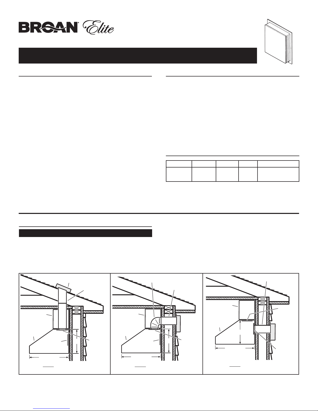
MODEL 331H or 332H
EXTERIOR BLOWER
10" ROUND
DUCT
SOFFIT
WALL HOOD
CANOPY
(island canopy
available)
TYPICAL ROOF MOUNTED INSTALLATION
DUCT
OPENING
COVER PLATE
24" or 27"
(Vertical discharge)
INSTALLER: Leave This Manual With The Homeowner
HOMEOWNER: Use And Care Information On Page 3
18"
ROUGH-IN
PLATE
10" ROUND ELBOW
10" ROUND DUCT
SOFFIT
WALL HOOD
CANOPY
(island canopy
available)
COVER PLATE
DUCT
OPENING
24" or 27"
18"
MODEL
331H
or 332H
EXTERIOR
BLOWER
ROUGH-IN
PLATE
TYPICAL WALL MOUNTED INSTALLATION
(Vertical discharge - elbow to horizontal)
TYPICAL WALL MOUNTED INSTALLATION
(Horizontal discharge)
Page 2
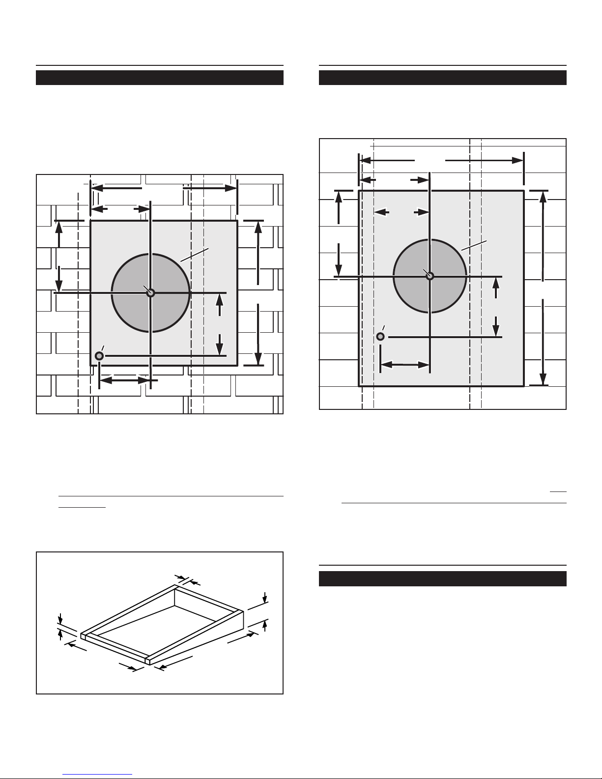
11" dia.
hole
29½"
1¼"
dia. hole
127/8"
10¾"
25"
7¼"
91/8"
Wa l l S tud
Wa l l S tud
REMOVE
SIDING
8½"
Pilot
Hole
OUTSIDE - WALL VIEW
20½"
11"
dia.
hole
103/8"
1¼"
dia. hole
8½"
20¾"
7¼"
91/8"
REMOVE
SHINGLES
Pilot
Hole
OUTSIDE - ROOF VIEW
PREPARE THE INSTALLATION
LOCATION
PREPARE THE INSTALLATION
LOCATION
2
ROOF INSTALLATIONS
1. Locate the blower on the rear slope of the roof.
Place it in a location to minimize duct run. The
location should be free of obstacles (T.V. leads,
electrical lines, etc.). Bear in mind, if the blower top
is level with the roof peak, it will not be seen from
the street. Keep this approximate location in mind
as you work from within the attic.
Figure 1
20¾"
8½"
103/8"
REMOVE
SHINGLES
Pilot
Pilot
Hole
Hole
11"
dia.
hole
20½"
Roof Rafter
1¼"
dia. hole
Roof Rafter
91/8"
WALL INSTALLATIONS
1. Choose a position on the outside wall. Make sure
that no wall studs, pipes or wires run through the
opening area.
Figure 3
24¾"
10¾"
REMOVE
SIDING
11" dia.
hole
127/8"
8½"
Wall Stud
Pilot
Pilot
Hole
Hole
28¼"
1¼"
dia. hole
91/8"
Wall Stud
7¼"
OUTSIDE - ROOF VIEW
From inside the attic space:
2. Drill a PILOT HOLE up through the roof, 8½"
from the
inside edge
From outside - on the roof:
Measure and mark the 20¾" x 20½" rectangle.
3.
Cut and remove only the shingles inside this
rectangle.
Measure and mark the 11" DIAMETER HOLE
4.
and the 1¼" DIAMETER HOLE. Cut these holes
all the way through the roof.
Figure 2
2"
5. For flat roof installations, build a curb that will
24¾"
mount the blower at a minimum pitch of 2/12. See
Figure 2. Discharge end of the blower should be
pointed away from prevailing winds.
of a ROOF RAFTER.
2"
28¼"
6¾"
7¼"
OUTSIDE - WALL VIEW
From inside the wall:
2. Drill a PILOT HOLE through the wall, 8½" from
the
inside edge
of a WALL STUD.
From outside - on the wall:
3. Measure and mark the 25" x 29½" rectangle.
Cut
and remove only the siding inside this rectangle.
4. Measure and mark the 11" DIAMETER HOLE
and the 1¼" DIAMETER HOLE. Cut these holes
all the way through the wall.
PREPARE THE BLOWER
ALL INSTALLATIONS
1. Unpack the blower assembly.
2. Remove the cover and screws.
3. Remove and discard cardboard from blower wheel.
4. Remove the wiring box cover and screws.
5. Attach an appropriate CSA approved cable con-
nector in the hole at the rear of the wiring box.
Page 3
INSTALL THE BLOWER
INSTALL THE BLOWER
3
ROOF INSTALLATIONS
1. Remove roofing nails from the upper 2/3 of the
shingles around the cutout area and carefully lift the
shingles to allow the back flashing sheet on the
blower housing to fit under them.
2. Center the blower ring in the 11" diameter hole,
making sure that the 1-1/4" diameter electrical
wiring hole aligns with the hole in the wiring box.
3. Attach the blower to the roof with the six screws
provided. All six holes in the back panel must be
filled, or any moisture that may get inside the
housing could leak into the house.
4. Using a good grade of roofing cement, seal all of the
shingles around the housing and flashing sheet as
well as the mounting screw heads.
5. Bring electrical wiring through the hole in the wiring
box and secure it according to local codes.
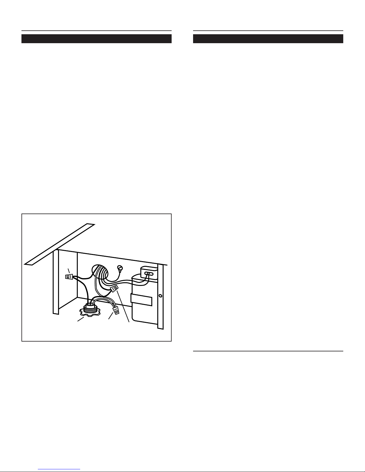
Figure 4
WALL INSTALLATIONS
1. Place a large bead of caulk on the back side of the
housing along the outer edge.
2. Center the blower ring in the 11" diameter hole,
making sure that the 1-1/4" diameter electrical
wiring hole aligns with the hole in the wiring box.
3. Attach blower to the wall with the six screws
provided. All six holes in the back panel must be
filled, or any moisture that may get inside the
housing could leak into the house.
4. Using a good grade of caulk, seal all around the
mounting screw heads.
5. Bring electrical wiring through the hole in the wiring
box and secure it according to local codes.
6. Make the electrical connections with the proper
connector for the type of wire being used. Connect
white to white, black to black, and green or bare
wire to green. See Figure 4.
BLACK
TO
BLACK
120 VAC
LINE IN
WHITE
TO
WHITE
GREEN
TO
GREEN
6. Make the electrical connections with the proper
connector for the type of wiring being used. Connect white to white, black to black, and the green or
bare wire to green. See Figure 4.
7. Replace wiring box cover and screws. Do not pinch
wiring under the cover.
7. Replace wiring box cover and screws. Do not
pinch wiring under cover.
8. Check for free movement of the damper before
installing housing cover and screws.
9. Turn on power and check operation of the blower.
10.Top and side flanges of the back plate may be
covered with trim strips. Do not block grille opening
at bottom with trim. It will adversely affect performance of the blower.
USE AND CARE
Disconnect electrical power supply and lock out service panel before cleaning or servicing this unit.
CLEANING
Remove cover and carefully vacuum blower and inside of housing. Be careful not to bend or otherwise
damage blower wheel.
8. Check for free movement of the damper before
installing housing cover and screws.
9. Turn on power and check operation of the blower.
MOTOR LUBRICATION
The motor is permanently lubricated. Do not oil or
disassemble motor.
Page 4
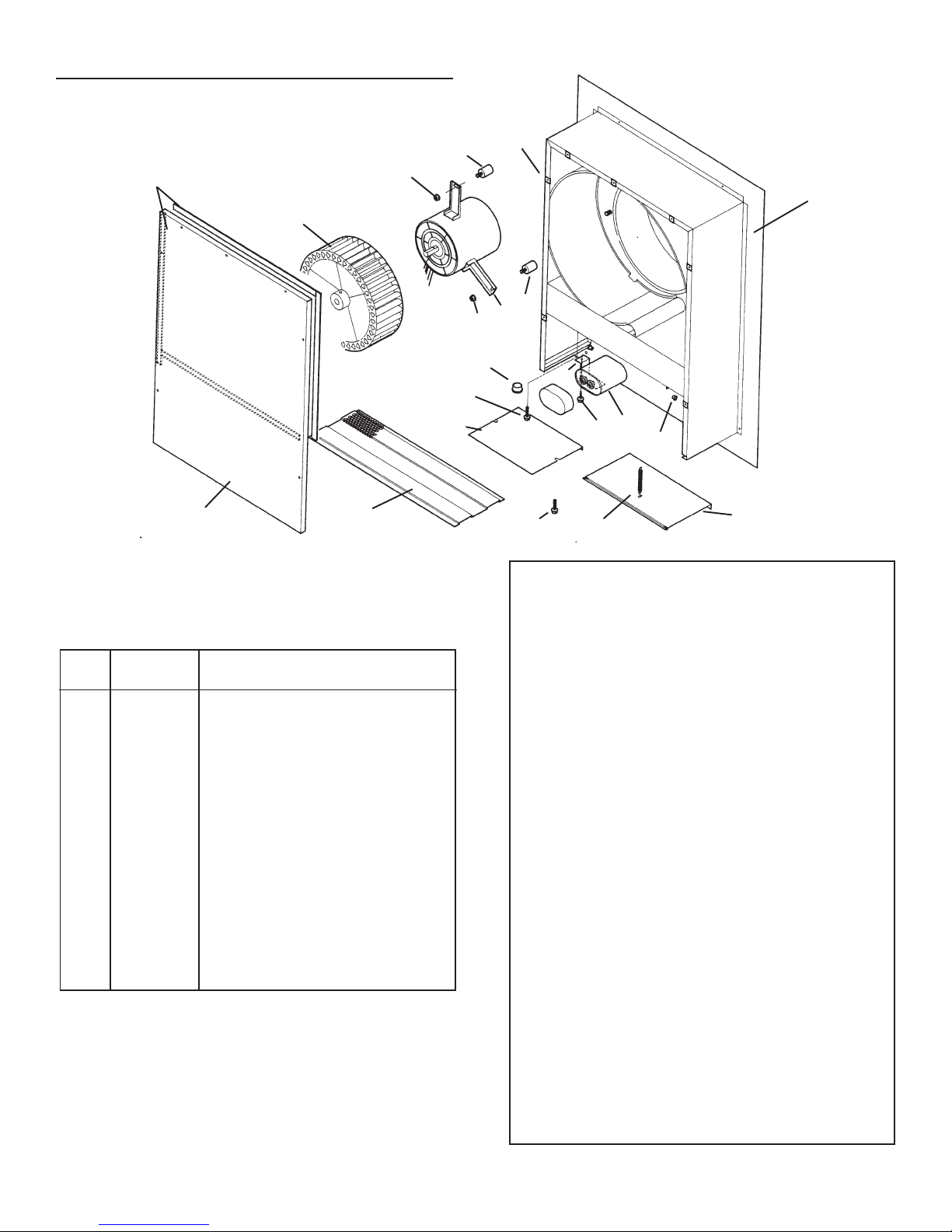
SERVICE PARTS
MODELS 332H & 331H
4
16
13
12
KEY
NO. PART NO. DESCRIPTION
1 97011795 Airbox Assembly
2 98008507 Damper
3 93260454 Sheet Metal Nut, #18-18 U-Type (7 req.)*
4 99100484 Isolator (3 req.)
5 99260477 Whiz Nut, 1/4" - 20 (3 req.)*
6 98008511 Grille
7 99100379 Heyco Damper (2 req.)
8 99080396 Motor W/Capacitor (Model 332)
99080397 Motor W/Capacitor (Model 331)
10 98008509 Wiring Box Cover
11 98008588 Capacitor Clamp
12 98008510 Airbox Cover
13 99020263 Blower Wheel (Model 332)
99020264 Blower Wheel (Model 331)
14 99140145 Damper Spring
15 99400055 Heyco
16 99100517 Foam Seal (4 req.)
17 99150471 Hex Screw, #10 - 32 x 1/2"*
18 99150535 Hex Screw, #8-16 x 3/8 (2 Req.)*
19 99271110 Capacitor 15 MFD
* Standard Hardware - May be purchased locally.
Always order replacement parts by Part No., not Key No.
6
4
3
5
1
4
8
5
15
11
17
14
18
19
7
2
10
18
BROAN-NUTONE ONE YEAR LIMITED WARRANTY
Broan-NuTone warrants to the original consumer purchaser of its
products that such products will be free from defects in materials or
workmanship for a period of one year from the date of original
purchase. THERE ARE NO OTHER WARRANTIES, EXPRESS OR
IMPLIED, INCLUDING, BUT NOT LIMITED TO, IMPLIED WARRANTIES OF MERCHANTABILITY OR FITNESS FOR A PARTICULAR PURPOSE.
During this one-year period, Broan-NuTone will, at its option, repair
or replace, without charge, any product or part which is found to be
defective under normal use and service.
THIS WARRANTY DOES NOT EXTEND TO FLUORESCENT
LAMP STARTERS AND TUBES. This warranty does not cover (a)
normal maintenance and service or (b) any products or parts which
have been subject to misuse, negligence, accident, improper
maintenance or repair (other than by Broan-NuTone), faulty installation or installation contrary to recommended installation instructions.
The duration of any implied warranty is limited to the one-year
period as specified for the express warranty. Some states do not
allow limitation on how long an implied warranty lasts, so the above
limitation may not apply to you.
BROAN-NUTONE’S OBLIGATION TO REPAIR OR REPLACE, AT
BROAN-NUTONE’S OPTION, SHALL BE THE PURCHASER’S
SOLE AND EXCLUSIVE REMEDY UNDER THIS WARRANTY.
BROAN-NUTONE SHALL NOT BE LIABLE FOR INCIDENTAL,
CONSEQUENTIAL OR SPECIAL DAMAGES ARISING OUT OF
OR IN CONNECTION WITH PRODUCT USE OR PERFORMANCE.
Some states do not allow the exclusion or limitation of incidental or
consequential damages, so the above limitation or exclusion may
not apply to you.
This warranty gives you specific legal rights, and you may also have
other rights, which vary from state to state. This warranty supersedes all prior warranties.
To qualify for warranty service, you must (a) notify Broan-NuTone
at the address or telephone number below, (b) give the model
number and part identification and (c) describe the nature of any
defect in the product or part. At the time of requesting warranty
service, you must present evidence of the original purchase date.
Broan-NuTone LLC Hartford, Wisconsin
www.broan.com 800-558-1711
Broan-NuTone Canada Mississauga, Ontario
www.broan.ca 877-896-1119
99043017E
Page 5

MODEL
331H
or 332H
EXTERIOR
BLOWER
WALL HOOD
CANOPY
(island canopy
available)
10" ROUND DUCT
SOFFIT
ROUGH-IN
PLATE
24" or 27"
18"
DUCT
OPENING
COVER
PLATE
MODÈLES 331H & 332H
Page Lm
VENTILATEUR À MONTAGE EXTÉRIEUR
POUR UTILISATION AVEC LES HOTTES RANGEMASTER ET LES VENTILATEURS ENCASTRÉS ECLIPSE
VEUILLEZ LIRE CES DIRECTIVES ET LES CONSERVER
5
AVERTISSEMENT
OBSERVEZ LES DIRECTIVES CI-DESSOUS DE MANIÈRE À RÉDUIRE LES RISQUES D’INCENDIE, DE CHOC ÉLECTRIQUE OU DE
BLESSURES CORPORELLES.
1. N’utilisez cet appareil qu’aux fins prévues par le fabricant. Si vous
avez des questions, communiquez avec le fabricant à l’adresse ou
au numéro de téléphone indiqués dans la garantie.
2. Avant de procéder à la réparation ou au nettoyage de l’appareil,
coupez l’alimentation du panneau d’entrée d’électricité et verrouillez
le dispositif de sectionnement afin d’ empêcher que le courant ne soit
accidentellement rétabli. S’il est impossible de verrouiller le dispositif
de sectionnement, fixez solidement un dispositif avertisseur, par
exemple une étiquette, au panneau d’entrée d’électricité.
3. La pose de l’appareil et les travaux d’électricité doivent être effectués
par des personnes qualifiées conformément à la réglementation en
vigueur, notamment les normes de la construction ayant trait à la
protection contre les incendies.
4. Pour éviter les refoulements, l’apport d’air doit être suffisant pour
brûler . les gaz produits par les appareils à combustion et les évacuer
dans le conduit de fumée (cheminée). .. Respectez les directives du
fabricant de l’appareil de chauffage et les normes de sécurité,
notamment celles publiées par la National Fire Protection Association (NFPA), l’American Society for Heating, les Refrigeration and
Air Conditioning Engineers (ASHRAE) et la règlementation locale.
5. Veillez à ne pas endommager le câblage électrique ou autres
connexions non apparentes lors de la découpe ou du perçage du
mur ou du plafond.
6. Les ventilateurs canalisés doivent toujours être ventilés à l’air libre.
7. Pour réduire les risques d’incendie, n’utilisez que des conduits
métalliques.
8. Cet appareil doit être mis à la terre.
PLANIFICATION DE LA POSE
TOUS LES TYPES DE POSE
1. L’emplacement du ventilateur doit être choisi de manière à
réduire le plus possible l’utilisation de conduits et de coudes.
REMARQUE : Une sortie horizontale exige le
repositionnement de la plaque d’ouverture du conduit. Voir
les instructions du manuel de la hotte.
ATTENTION
1. Cet appareil ne doit servir qu’à la ventilation générale. Ne vous en
servez pas pour éliminer des matières ou des vapeurs dangereuses ou explosives.
2. Pour ne pas endommager les roulements de moteur, déséquilibrer les pales ou les rendre bruyantes, débarrassez l’appareil de
la poussière de plâtre, de construction, etc.
3. Veuillez lire l’étiquette de spécifications du produit pour obtenir
plus de renseignements, notamment sur les normes.
4. Le circuit électrique, y compris la commande de régime (le cas
échéant), doit avoir au minimum une puissance nominale de 6
ampères pour le modèle 332H ou d’au moins 3 ampères pour le
modèle 331H.
SPÉCIFICATIONS
MODÈLE VOLTS AMPÈRES PCM DIMENSION
DU CONDUIT
331H 120 2.4 600 10" (25,4 cm) de diam.
332H 120 5.7 900 10" (25,4 cm) de diam.
2. Lorsque cela est envisageable, le ventilateur doit être centré entre les poteaux
muraux ou les chevrons du toit.
3. Évitez les tuyaux, les fils ou autres conduits qui peuvent passer dans les murs.
4. Assurez-vous d’avoir suffisamment d’espace pour placer les
conduits de transition entre le ventilateur et les conduits de
raccordement.
5. Pour de meilleurs résultats, placez les conduits de transition le
plus près possible du ventilateur (encastré).
NOTA: Décharge horizontal exige la relocalisation de la plaque du décharge. Voir
le manuel de hotte pour des instructions.
MODEL 331H or 332H
MODÈLE 331H ou 332H
EXTERIOR BLOWER
VENTILATEUR EXTÉRIEUR
10" ROUND
CONDUIT ROND DE
DUCT
25,4 cm (10 po)
SOFFIT
SOFFITTE
VERRIÈRE
WALL HOOD
HOTTE DE MUR
CANOPY
(island canopy
(verrière de île
available)
disponible)
POSE TYPE - VENTILATEUR MONTÉ SUR LE
PROPRIÉTAIRE : La page 7 contient des renseignements portant sur l’utilisation et l’entretien
DUCT
OPENING
PLAQUE DU
COVER PLATE
DÉCHARGE
61 ou 68,6 cm
24" or 27"
(24 ou 27 po)
(Décharge verticale)
18"
INSTALLATEUR : Veuillez laisser ce manuel au propriétaire
45,7 cm
(18 po)
ROUGH-IN
PLAQUE
PLATE
DU
VENTILA-
TEUR
TOIT
COUDE DE
10" ROUND ELBOW
25,4 cm (10 po)
SOFFIT
SOFFITTE
VERRIÈRE
WALL HOOD
CANOPY
HOTTE DE MUR
(island canopy
(verrière de île
available)
disponible)
DUCT
OPENING
PLAQUE DU
COVER PLATE
DÉCHARGE
61 ou 68,6 cm
24" or 27"
(24 ou 27 po)
POSE TYPE - VENTILATEUR MONTÉ SUR LE
CONDUIT ROND
10" ROUND DUCT
DE 25,4 cm (10 po)
MODÈLE
MODEL
331H
331H ou 332H
or 332H
VENTILA-
EXTERIOR
TEUR
BLOWER
EXTÉRIEUR
ROUGH-IN
18"
PLAQUE
PLATE
DU
VENTILA-
TEUR
45,7 cm (18 po)
MUR
(Décharge verticale - coude à horizontal)
CONDUIT ROND
DE 25,4 cm (10 po)
SOFFITTE
VERRIÈRE
HOTTE DE MUR
(verrière de île
disponible)
45,7 cm
(18 po)
61 ou 68,6 cm
(24 ou 27 po)
PLAQUE
DU
DÉCHARGE
MODÈLE
331H ou 332H
VENTILATEUR
EXTÉRIEUR
PLAQUE DU
VENTILA-
TEUR
POSE TYPE - VENTILATEUR MONTÉ SUR LE MUR
(Décharge horizontal)
Page 6

PRÉPAREZ L'ENDROIT POUR
20½"
11"
dia.
hole
103/
8"
1¼"
dia. hole
8½"
20¾"
7¼"
91/
8"
REMOVE
SHINGLES
Pilot
Hole
OUTSIDE - ROOF VIEW
11" dia.
hole
29½"
1¼"
dia. hole
127/8"
10¾"
25"
7¼"
91/8"
Wa l l S t u d
Wa l l S t u d
REMOVE
SIDING
8½"
Pilot
Hole
OUTSIDE - WALL VIEW
L'INSTALLATION
INSTALLATIONS SUR LE TOIT INSTALLATIONS MURALES
PRÉPAREZ L'ENDROIT POUR
L'INSTALLATION
6
1. Positionnez le ventilateur sur la pente arrière du toit. Placezle dans un endroit qui minimisera la longueur du conduit de
ventilation. Cet endroit doit être exempt d'obstacles (câble de
téléviseur, lignes électriques, etc.) Souvenez-vous que si le
dessus du ventilateur est à ras de la pointe du toit, il ne sera
pas vu de la rue. Souvenez-vous de cet emplacement
approximatif pendant que vous travaillez de l'intérieur de
l'entre-toit.
ILLUSTRATION 1
ENLEVEZ LES
REMOVE
BARDEAUX
264 mm (10 3/
103/
8"
8 po)
SHINGLES
Chevron
Orifice d’un
Roof Rafter
diamètre de
1¼"
32 mm (1 ¼ po)
dia. hole
216 mm
8½"
(8 ½ po)
Avant-
Pilot
Pilot
trou
Hole
Hole
527 mm
20¾"
(20 ¾ po)
Orifice d’un
11"
diamètre de
279 mm (11 po)
dia.
hole
Chevron
232 mm
Roof Rafter
(9 1/
91/
8"
8 po)
521 mm
(20 1/2 po)
20½"
1. Choisissez une position sur le mur extérieur. Assurez qu'il n'y
a pas de colombage, tuyaux ou fils dans l'endroit qui sera
ouvert.
ILLUSTRATION 3
327 mm
127/8"
(12-7/8 po)
628.7 mm (24¾ po)
273 mm
10¾"
(10¾ po)
216 mm
8½"
(8½ po)
Wall Stud
Poteau mural
Orifice d’un
diamètre de
1¼"
32 mm
dia. hole
(1¼ po)
Pilot
Pilot
Avant-
trou
Hole
Hole
25"
ENLEVEZ
REMOVE
SIDING
PAREMENT
184 mm
7¼"
(7¼po)
LE
Orifice
d’un
11" dia.
diamètre
de
hole
279 mm
(11 po)
232 mm
91/8"
(9-1/8 po)
Wall Stud
Poteau mural
717.6 mm
29½"
(28¼ po)
184 mm
7¼"
(7 ¼ po)
OUTSIDE - ROOF VIEW
EXTÉRIEUR – VUE DU TOIT
De l’intérieur du grenier
2. Percez un AVANT-TROU à travers le toit, à une distance de
216 mm (8 ½ po) du
De l’extérieur –sur le toit :
3. Mesurez et tracez un rectangle de 527 mm x 521 mm
(20 ¾ po x 20 ½ po).
bardeaux qui se trouvent à l’intérieur de ce rectangle.
4. Mesurez et tracez un ORIFICE D’UN DIAMÈTRE DE 279
MM (11 PO) et un ORIFICE D’UN DIAMÈTRE DE 32 MM
(1 ¼ PO). Découpez ces orifices de part en part du toit.
ILLUSTRATION 2
51 mm
(2 po)
2"
rebord intérieur
d’un CHEVRON.
Coupez et retirez seulement les
51 mm
(2 po)
2"
171.5 mm
(6¾ po)
6¾"
628.7 mm
24¾"
(24¾ po)
5. Pour les installations sur les toits plats, fabriquez une bordure
qui inclinera le ventilateur de 2/12 au minimum. Voir ill. 2.
L'extrémité de la décharge du ventilateur doit pointer du côté
opposé aux vents dominants.
28¼"
717.6 mm
(28¼ po)
OUTSIDE - WALL VIEW
EXTÉRIEUR –VUE DU MUR
De l’intérieur du mur :
2. Percez un AVANT-TROU à travers le mur, à une distance de
216 mm (8 ½ po) du
MURAL.TUD.
De l’extérieur –sur le mur :
3. Mesurez et tracez un rectangle de 635 mm x 749 mm (25
po x 29,5 po). Coupez et retirez seulement les bardeaux qui
se trouvent à l’intérieur de ce rectangle.
4. Mesurez et tracez un ORIFICE D’UN DIAMÈTRE DE 279
MM (11 PO) et un ORIFICE D’UN DIAMÈTRE DE 32 MM
(1 ¼ PO). Découpez ces orifices de part en part du mur.
rebord intérieur
d’un POTEAU
PRÉPAREZ LE VENTILATEUR
TOUTES LES INSTALLATIONS
1. Déballez l'ensemble du ventilateur.
2. Enlevez le couvercle et les vis.
3. Enlevez et jetez le carton de la roue du ventilateur.
4. Enlevez le couvercle de la boîte des fils et les vis.
5. Attachez une pince de raccordement appropriée approuvée
par l'ACNOR dans le trou à l'arrière de la boîte des fils.
Page 7

POSE DU VENTILATEUR
INSTALLATION DU VENTILATEUR
Page Lm
7
POSE DU VENTILATEUR
1. Retirez les premiers deux tiers des clous à toiture des
bardeaux se trouvant autour de la surface de découpe puis
soulevez délicatement les bardeaux afin de glisser le solin en
dessous.
2. Centrez l’anneau de ventilateur dans le trou de 11" (27,9 cm)
de diamètre, en vous assurant que le trou de 1-1/4" (3,2 cm)
pour le câblage électrique coïncide avec l’orifice du boîtier de
câblage.
3. Fixez le ventilateur au toit à l’aide des six vis incluses. Les six
trous du panneau arrière doivent être couverts, sans quoi
l’humidité peut pénétrer à l’intérieur du ventilateur et couler
dans l’habitation.
4. Imperméabilisez tous les bardeaux autour du boîtier et du
solin ainsi que les têtes de vis de montage à l’aide d’une colle
pour toiture de bonne qualité.
5. Faites passer le câblage électrique par l’ouverture du boîtier
de câblage et fixez-le en respectant la réglementation locale.
Figure 4
POSE SUR UN MUR
1. Appliquez une large bande de produit à calfeutrer à l’arrière
du boîtier, le long du rebord extérieur.
2. Centrez l’anneau de ventilateur dans le trou de 11" (27,9 cm)
de diamètre, en vous assurant que le trou de 1-1/4" (3,2 cm)
pour le câblage électrique coïncide avec l’orifice du boîtier
de câblage.
3. Fixez le ventilateur au mur à l’aide des six vis incluses. Les
six trous du panneau arrière doivent être couverts, sans quoi
l’humidité peut pénétrer à l’intérieur du ventilateur et couler
dans l’habitation.
4. Imperméabilisez le pourtour des têtes de vis de montage à
l’aide d’un produit à calfeutrer de bonne qualité.
5. Faites passer le câblage électrique par l’ouverture du boîtier
de câblage et fixez-le en respectant la réglementation locale.
6. Effectuez les branchements électriques en utilisant le
connecteur convenant au type de câblage utilisé. Branchez
les fils noirs ensemble, les fils blancs ensemble et le fil vert
ou le fil dénudé avec le fil vert. Voir Figure 4.
7. Replacez le couvercle du boîtier de câblage et les vis. Ne
pincez pas le câblage sous le couvercle.
8. Assurez-vous que le clapet bouge librement avant d’installer
le couvercle du boîtier et les vis.
BLACK
NOIR
TO
AVEC
BLACK
NOIR
120 VAC
ENTRÉE
LINE IN
120V
6. Effectuez les branchements électriques en utilisant le
connecteur convenant au type de câblage utilisé. Branchez
les fils noirs ensemble, les fils blancs ensemble, et le fil vert
ou le fil dénudé avec le fil vert. Voir Figure 4.
7. Replacez le couvercle du boîtier de câblage et les vis. Ne
pincez pas le câblage sous le couvercle.
8. Assurez-vous que le clapet bouge librement avant d’installer
le couvercle du boîtier et les vis.
9. Mettez l’appareil sous tension et vérifiez le fonctionnement
du ventilateur.
WHITE
BLANC
TO
AVEC
WHITE
BLANC
GREEN
VERT
TO
AVEC
GREEN
VERT
9. Mettez l’appareil sous tension et vérifiez le fonctionnement
du ventilateur.
10. Les rebords supérieurs et latéraux de la plaque arrière
doivent être recouverts avec des tringles de finissage. Ne
bloquez pas la partie inférieure de la grille à air avec les
tringles. Le rendement du ventilateur en serait modifié.
UTILISATION ET ENTRETIEN
Débranchez l’alimentation électrique et verrouillez le panneau
d’entrée d’électricité avant de nettoyer ou de réparer l’appareil.
NETTOYAGE
Retirez le couvercle et passez soigneusement l’aspirateur à
l’intérieur du boîtier. Veillez à ne pas courber ou endommager
la roue du ventilateur.
LUBRIFICATION DU MOTEUR
Le moteur est lubrifié en permanence. Il ne doit pas être huilé ni
démonté.
Page 8

PIÈCES DE RECHANGE
MODÈLES 332H ET 331H
8
16
13
12
REPÈRE N° PIÈCE DESCRIPTION
1 97011795 Boîte à air
2 98008507 Clapet
3 93260454 Écrou à tôle, n° 18-18 Type U (7)*
4 99100484 Isolateur (3)
5 99260477 Écrou à rondelle, 1/4" - 20 (3)*
6 98008511 Grille
7 99100379 Butée de clapet (2)
8 99080396 Moteur à condensateur (modèle 332H)
99080397 Moteur à condensateur (modèle 331H)
10 98008509 Couvercle du boîtier de câblage
11 98008588 Bride de condensateur
12 98008510 Capot de boîte à air
13 99020263 Roue du ventilateur (modèle 332H)
99020264 Roue du ventilateur (modèle 331H)
14 99140145 Ressort de clapet
15 99400055 Butée
16 99100517 Joint de mousse (4)
17 99150471 Vis à tête hex., n° 10 - 32 x 1/2"*
18 99150535 Vis à tête hex., n° 8-16 x 3/8 (2) *
19 99271110 Condensateur 15 MFD
*Quincaillerie ordinaire - vendu séparément.
Veuillez commander les pièces par N° PIÈCE - et non par N°
REPÈRE.
6
4
3
5
1
4
8
5
15
11
17
10
18
Broan garantit à l’acheteur consommateur original, de ses produits
qu’ils sont exempts de défauts dans les matières premières ou la
main-d’oeuvre pour une période d’un an à compter de la date
d’achat original. IL N’Y A PAS D’AUTRES GARANTIES,
EXPRIMÉES OU IMPLICITES, INCLUANT MAIS NON PAS LIMITÉ
AUX GARANTIES IMPLICITES POUR FIN DE
COMMERCIALISATION ET DE CONVENANCE DANS UN BUT
PARTICULIER.
Pendant cette période d’un an, Broan, à son choix, réparera ou
remplacera, gratuitement, tout produit ou pièce qui s’avère
défectueux sous utilisation et service normaux.
CETTE GARANTIE NE COUVRE PAS LES DÉMARREURS DE
LAMPES FLUORESCENTES ET LES TUBES. Cette garantie ne
couvre pas (a) l’entretien et le service normal ou (b) tout produit ou
pièce endommagé par suite de mauvais usage, négligence, accident, entretien inapproprié ou réparation (autre que par Broan),
mauvais installation ou installation contraire au mode d’installation
recommandé.
La durée de toute garantie implicite est limitée à une période d’un
an tel que spécifié pour la garantie exprimée. Certains états ne
permettent pas la limitation de la durée d’une garantie implicite, la
limitation ci-dessus peut donc ne pas s’appliquer à vous.
L’ENGAGEMENT DE BROAN DE RÉPARER OU DE
REMPLACER, AU CHOIX DE BROAN, SERA LA SEULE OBLIGATION EXCLUSIVE SOUS CETTE GARANTIE. BROAN NE SE
TIENDRA PAS RESPONSABLE DES DOMMAGES DIRECTS,
INDIRECTS OU SPÉCIAUX SURVENANT À CAUSE DE OU EN
RAPPORT À L’UTILISATION OU LA PERFORMANCE DE SES
PRODUITS.
Cette garantie vous donne des droits légaux spécifiques et il se
peut que vous ayez d’autres droits qui varient d’un état à un autre.
Cette garantie annule toutes les garanties précédentes.
Pour le service sous garantie, vous devez (a) aviser Broan á
l'adresse ci-dessous, (b) donner le numéro du modèle et
l’identification de la pièce et (c) décrire la nature de tout défaut
dans le produit ou la pièce. Au temps de demander le service sous
garantie, vous devez présenter une preuve de la date d’achat
original.
Broan-NuTone LLC Hartford, Wisconsin
www.broan.com 800-558-1711
Broan-NuTone Canada Mississauga, Ontario
www.broan.ca 877-896-1119
19
18
14
GARANTIE LIMITÉE D’UN AN DE BROAN
7
2
99043017E
Page 9

MODEL
331H
or 332H
EXTERIOR
BLOWER
WALL HOOD
CANOPY
(island canopy
available)
10" ROUND DUCT
SOFFIT
ROUGH-IN
PLATE
24" or 27"
18"
DUCT
OPENING
COVER
PLATE
MODELOS 331H Y 332H
VENTILADOR DE MONTAJE EXTERIOR
PARA USARSE CON CAMPANAS RANGEMASTER Y VENTILADORES ECLIPSE DE TIRO DESCENDENTE
LEA Y CONSERVE ESTAS INSTRUCCIONES
Page Lm
9
ADVERTENCIA
PARA REDUCIR EL RIESGO DE INCENDIOS, DESCARGAS ELÉCTRICAS
O LESIONES PERSONALES OBSERVE LAS SIGUIENTES
PRECAUCIONES:
1. Use la unidad sólo de la manera indicada por el fabricante. Si tiene
preguntas, comuníquese con el fabricante en la dirección o el número
telefónico que se incluye en la garantía.
2. Antes de dar servicio o limpiar la unidad, interrumpa el suministro
eléctrico en el panel de servicio y bloquee los medios de desconexión del
servicio para evitar que la electricidad se reanude accidentalmente.
Cuando no sea posible bloquear los medios de desconexión del servicio,
fije firmemente en un lugar prominente del panel de servicio un dispositivo
de advertencia , como por ejemplo una etiqueta.
3. Una o más personas calificadas deben realizar el trabajo de instalación
y el cableado eléctrico, de acuerdo con todos los códigos y normas
correspondientes, incluidos los códigos y normas de construcción
específicos sobre protección contra incendios.
4. Se necesita suficiente aire para que se lleve a cabo una combustión
adecuada y para la descarga de los gases a través del tubo de humos
(chimenea) del equipo quemador de combustible a fin de evitar los
contratiros. Siga las directrices y las normas de seguridad del fabricante
del equipo de calentamiento, como aquellos publicados por la Asociación
Nacional de Protección contra Incendios (National Fire Protection
Association, NFPA), y la Sociedad Americana de Ingenieros en
Calefacción, Refrigeración y Aire Acondicionado (American Society for
Heating, Refrigeration and Air Conditioning Engineers, ASHRAE), y las
autoridades de los códigos locales.
5. Al cortar o perforar a través de la pared o del cielo raso, no dañe el
cableado eléctrico ni otros servicios ocultos.
6. Los ventiladores con conductos siempre se deben conectar hacia el
exterior.
7. Para reducir el riesgo de incendio, use solamente conductos metálicos.
8. Esta unidad se debe conectar a tierra.
PLANIFIQUE LA INSTALACIÓN
TODAS LAS INSTALACIONES
1. Ubique el ventilador de manera que la longitud de los conductos y el
número de codos y transiciones necesarios sean mínimos.
Por favor note: cuando use el ventilador con el tiro descendente
Eclipse de Broan: El tiro descendente tiene una descarga de 3¼ x 10"
(8.3 x 25.4 cm) Hay transiciones disponibles para conectarlo a la
entrada redonda de 10" (25.4 cm) en este ventilador de montaje
exterior.
MODEL 331H or 332H
VENTILADOR EXTERIOR
EXTERIOR BLOWER
MODELO 331H o 332H
CONDUCTO
10" ROUND
REDONDO DE
DUCT
10" (25.4 CM)
CODO REDONDO
10" ROUND ELBOW
10" (25.4 CM)
PRECAUCIÓN
1. Sólo para uso en ventilación general. No lo use para descargar materiales
ni vapores peligrosos o explosivos.
2. Para evitar daños a los cojinetes del motor y rotores ruidosos y/o no
equilibrados, mantenga el rocío de yeso, el polvo de la construcción, etc.
alejado de la unidad de accionamiento.
3. Por favor lea la etiqueta de especificaciones que tiene el producto para
ver información y requisitos adicionales.
4. El circuito eléctrico, incluido el control de velocidad (si se usa) debe tener
una capacidad nominal mínima de 6 amperios para el Modelo 332H o 3
amperios para el Modelo 331H.
ESPECIFICACIONES
MODELO VOLTIOS AMPERIOS PCM TAMAÑO DE
CONDUCTO
331H 120 2.4 600 10" (25.4 cm) DIÁM.
332H 120 5.7 900 10" (25.4 cm) DIÁM.
PLANIFIQUE LA INSTALACIÓN
2. Cuando sea posible, el ventilador se debe centrar entre los montantes de
la pared o entre las vigas del techo.
3. Evite la tubería, cables u otros conductos que puedan estar tendidos por
la pared.
4. Asegúrese de que haya suficiente espacio para cualquier transición que
pueda necesitarse entre el ventilador y los conductos de conexión.
5. Para obtener el mejor rendimiento, coloque las transiciones lo más cerca
posible del ventilador (esto es, el tiro descendente)
NOTA: La descarga horizontal requiere la reubicación de la placa de
cubierta de la abertura del conducto. Consulte las instrucciones en el
manual de la campana.
CONDUCTO REDONDO
CONDUCTO
10" ROUND DUCT
REDONDO DE
10" (25.4 CM)
DE 10" (25.4 CM)
SOFFIT
PLAFÓN
WALL HOOD
CUBIERTA DE
CANOPY
LA CAMPANA
(island canopy
DE PARED
available)
(hay disponible
una cubierta
tipo isla)
INSTALACIÓN TÍPICA DE MONTAJE EN EL TECHO
PARA LA PERSONA QUE REALIZA LA INSTALACIÓN: Entregue este manual al dueño de la casa
AL DUEÑO DE LA CASA: Las instrucciones de uso y cuidado se encuentran en la página 11.
DUCT
PLACA DE
OPENING
CUBIERTA DE LA
COVER PLATE
ABERTURA DEL
CONDUCTO
24" (60.9 cm) ó
24" or 27"
27" (68.6 cm)
(descarga vertical)
18"
18"
(45.7
cm)
PLACA
SIN
ROUGH-IN
ACABAR
PLATE
PLAFÓN
SOFFIT
CUBIERTA DE LA
WALL HOOD
CAMPANA DE
CANOPY
PARED (hay
(island canopy
disponible una
available)
cubierta tipo isla)
INSTALACIÓN TÍPICA DE MONTAJE EN
PLACA DE
DUCT
PLACA DE
CUBIERTA DE LA
OPENING
CUBIERTA DE LA
COVER PLATE
ABERTURA DEL
ABERTURA DEL
CONDUCTO
CONDUCTO
24" (60.9 cm) ó
24" or 27"
27" (68.6 cm)
(descarga vertical, codo a horizontal)
18"
18"
(45.7
cm)
MODEL
VENTILADOR
331H
or 332H
EXTERIOR
EXTERIOR
MODELO
BLOWER
331H o 332H
ROUGH-IN
PLACA
PLATE
SIN
ACABAR
LA PARED
PLAFÓN
CUBIERTA DE LA
CAMPANA DE
PARED (hay
disponible una
cubierta tipo isla)
INSTALACIÓN TÍPICA DE MONTAJE EN LA PARED
18"
(45.7
cm)
24" (60.9 cm) ó
27" (68.6 cm)
descarga horizontal)
PLACA DE
CUBIERTA DE LA
ABERTURA DEL
CONDUCTO
VENTILADOR
EXTERIOR
MODELO
331H o 332H
PLACA
SIN
ACABAR
Page 10

PREPARE EL LUGAR DE LA
20½"
11"
dia.
hole
103/
8"
1¼"
dia. hole
8½"
20¾"
7¼"
91/
8"
REMOVE
SHINGLES
Pilot
Hole
OUTSIDE - ROOF VIEW
11" dia.
hole
29½"
1¼"
dia. hole
127/8"
10¾"
25"
7¼"
91/8"
Wa l l S t u d
Wa l l S t u d
REMOVE
SIDING
8½"
Pilot
Hole
OUTSIDE - WALL VIEW
INSTALACIÓN
INSTALACIONES EN EL TECHO
PREPARE EL LUGAR DE LA
INSTALACIÓN
INSTALACIONES EN LA PARED
10
1. Ubique el ventilador en la pendiente posterior del techo. Colóquelo
en un área en la cual minimice la longitud del tramo de conductos.
Esta área debe estar libre de obstáculos (cables de T.V., cables
eléctricos, etc.). Recuerde que si la parte superior del ventilador
está al ras del pico del techo, no se verá desde la calle.
Mantenga en mente esta ubicación aproximada mientras trabaja
desde el ático.
Figura 1
527 mm
20¾"
(20 ¾ plg.)
216 mm
8½"
(8 ½ plg.)
Orificio de
11"
279 mm (11 plg.)
de diám.
dia.
hole
Viga del techo
232 mm
Roof Rafter
(9 1/8
91/
8"
plg)
521 mm
(20 1/2 plg.)
20½"
264 mm
103/
8"
(10 3/8 plg.)
QUITE LAS
REMOVE
TEJAS
SHINGLES
Orificio
Pilot
Pilot
piloto
Hole
Hole
Viga del techo
Orificio de
Roof Rafter
32 mm
(1 ¼ plg.) de
1¼"
diám.
dia. hole
184 mm
7¼"
(7 ¼ plg.)
1. Seleccione un lugar en la pared exterior. Asegúrese de que no
haya montantes de la pared, tubería ni cables tendidos en el
área de la abertura.
2. Haga un orificio guía en el centro del área de la abertura.
Figura 3
327 mm
127/8"
(12-7/8 plg.)
628.7 mm (24¾ plg)
273 mm
10¾"
(10¾ plg.)
216 mm
8½"
(8½ plg.)
Wall Stud
Orificio de
Montante de la pared
32 mm
1¼"
(1 ¼ plg.) de
dia. hole
diám.
Orificio
Pilot
Pilot
piloto
Hole
Hole
25"
REMOVE
QUITE EL
SIDING
FORRADO
184 mm
7¼"
(7¼plg)
Orificio de
279 mm
11" dia.
(11 plg.) de
hole
diám.
717.6 mm
29½"
232 mm
91/8"
(9 1/8 plg)
(28¼ plg)
Wall Stud
Montante de la pared
OUTSIDE - ROOF VIEW
EXTERIOR - VISTA DEL TECHO
Desde el interior del espacio del ático:
2. Haga un ORIFICIO PILOTO a través del techo, a una distancia
de 21.6 cm (8 ½”) del
Desde el exterior, en el techo:
3. Mida y marque el rectángulo de 52.7 x 52.1 cm (20 ¾” x 20 ½”).
Corte y quite sólo las tejas que se encuentran dentro de este
rectángulo.
4. Mida y marque el ORIFICIO DE 27.9 CM (11") y el ORIFICIO DE
3.2 CM (1 1/4") de DIÁMETRO. Haga estos orificios totalmente
a través del techo.
FIGURA 2
51 mm
(2 plg)
2"
borde interior
de una VIGA DEL TECHO.
51 mm
(2 plg)
2"
171.5 mm
(6¾ plg)
6¾"
628.7 mm
24¾"
(24¾ plg)
5. Para instalar un ventilador sobre un techo plano, construya un
bastidor para soportar el ventilador, con una pendiente
mínima de 2/12. El extremo de descarga del ventilador debe
apuntar en dirección contraria a los vientos dominantes.
28¼"
717.6 mm
(28¼ plg)
OUTSIDE - WALL VIEW
EXTERIOR - VISTA DE LA PARED
Desde el interior de la pared:
2. Haga un ORIFICIO PILOTO a través de la pared, a una distancia
de 21.6 cm (8 ½”) del
PARED.
Desde el exterior, en la pared:
3. Mida y marque el rectángulo de 63.5 x 74.9 cm (25" x 29 ½”).
y quite sólo el forrado que se encuentra dentro de este rectángulo.
4. Mida y marque el ORIFICIO DE 27.9 CM (11") y el ORIFICIO DE
3.2 CM (1 1/4") de DIÁMETRO. Haga estos orificios totalmente a
través de la pared.
borde interior
de un MONTANTE DE LA
Corte
PREPARE EL VENTILADOR
TODAS LAS INSTALACIONES
1. Desempaque el conjunto del ventilador
2. Quite la cubierta y los tornillos.
3. Quite y deseche el cartón de la rueda del ventilador.
4. Quite la cubierta de la caja de conexiones y los tornillos.
5. Coloque un conectador de cables apropiado, aprobado por U.L.,
en el orificio que se encuentra en la parte posterior de la caja de
conexiones.
Page 11

INSTALE EL VENTILADOR
INSTALE EL VENTILADOR
Page Lm
11
INSTALACIONES EN EL TECHO
1. Quite los clavos del techo de las 2/3 partes de las tejas
superiores que se encuentran alrededor del área de corte y
levante las tejas con cuidado para permitir que la hoja cubrejuntas
posterior de la cubierta del ventilador se ajuste debajo de ellas.
2. Centre el anillo del ventilador en el orificio de 11" (27.9 cm),
asegurándose de que el orificio del cableado eléctrico, de 1 ¼”
(3.2 cm) de diámetro, quede alineado con el orificio de la caja de
conexiones.
3. Monte el ventilador en el techo con los seis tornillos que se
proporcionan. Los seis orificios del panel posterior deben
quedar cubiertos, de otra manera la humedad que penetre en la
cubierta se puede filtrar al interior de la casa.
4. Utilizando un cemento para techo de buena calidad, selle todas
las tejas alrededor de la cubierta y de la hoja cubrejuntas, así
como alrededor de la cabeza de los tornillos de montaje.
5. Pase los cables eléctricos a través del orificio de la caja de
conexiones y asegúrelos de acuerdo con los códigos locales.
Figura 4
INSTALACIONES EN LA PARED
1. Coloque un reborde grande de material de calafateo en el lado
posterior de la cubierta, a lo largo del borde externo.
2. Centre el anillo del ventilador en el orificio de 11" (27.9 cm),
asegurándose de que el orificio del cableado eléctrico, de 1 ¼”
(3.2 cm) de diámetro, quede alineado con el orificio de la caja de
conexiones.
3. Monte el ventilador en la pared con los seis tornillos que se
proporcionan. Los seis orificios del panel posterior deben quedar
cubiertos, de otra manera la humedad que penetre en la
cubierta se puede filtrar al interior de la casa.
4. Utilizando material de calafateo de buena calidad, selle alrededor
de la cabeza de los tornillos de montaje.
5. Pase los cables eléctricos a través del orificio de la caja de
conexiones y asegúrelos de acuerdo con los códigos locales.
6. Haga las conexiones eléctricas utilizando el conectador adecuado
para el tipo de cable que está usando. Conecte blanco con
blanco, negro con negro y verde con verde o con el hilo desnudo.
Consulte la Figura 4.
7. Vuelva a colocar la cubierta de la caja de conexiones y los
tornillos. No permita que los cables queden atrapados debajo de
la cubierta.
8. Verifique el movimiento libre del regulador de tiro antes de
instalar la cubierta y los tornillos.
BLACK
NEGRO
TO
A
BLACK
NEGRO
LÍNEA DE
120 VAC
ENTRADA
LINE IN
DE 120 V
6. Haga las conexiones eléctricas utilizando el conectador adecuado
para el tipo de cables que está usando. Conecte blanco con
blanco, negro con negro y verde con verde o con el hilo desnudo.
Consulte la Figura 4.
7. Vuelva a colocar la cubierta de la caja de conexiones y los
tornillos. No permita que los cables queden atrapados debajo de
la cubierta.
8. Verifique el movimiento libre del regulador de tiro antes de
instalar la cubierta y los tornillos.
WHITE
BLANCO
TO
A BLANCO
WHITE
GREEN
VERDE
TO
A VERDE
GREEN
9. Suministre energía y revise la operación del ventilador.
10. Las aletas superior y laterales de la placa posterior se pueden
cubrir con tiras de adorno. No obstruya con la tira de adorno la
abertura de la rejilla que se encuentra en la parte inferior. Si lo
hace afectará adversamente el funcionamiento del ventilador.
USO Y CUIDADO
Desconecte el suministro eléctrico y bloquee el panel de servicio
antes de limpiar o dar servicio a esta unidad.
LIMPIEZA
Quite la cubierta y cuidadosamente aspire el ventilador y el interior
de la cubierta. Tenga cuidado de no doblar la rueda del ventilador
ni dañarla de alguna otra manera.
LUBRICACIÓN DEL MOTOR
El motor está permanentemente lubricado. No lubrique ni desmonte
el motor.
9. Suministre energía y revise la operación del ventilador.
Page 12

PIEZAS DE REPUESTO
MODELOS 331H Y 332H
12
16
5
13
17
10
12
CLAVE
N.º PIEZA Nº. DESCRIPCIÓN
1 97011795 Conjunto de la caja de ventilación
2 98008507 Regulador de tiro
3 93260454 Tuerca para metales, #18-18 tipo U (7 req.)*
4 99100484 Aislador (3 req.)
5 99260477 Tuerca Whiz, 1/4" - 20 (3 req.)*
6 98008511 Rejilla
7 99100379 Regulador de tiro Heyco (2 req.)
8 99080396 Motor con capacitor (Modelo 332H)
10 98008509 Cubierta de la caja de conexiones
11 98008588 Pinza del capacitor
12 98008510 Cubierta de la caja de ventilación
13 99020263 Rueda del ventilador (Modelo 332H)
14 99140145 Resorte del regulador de tiro
15 99400055 Heyco
16 99100517
17 99150471 Tornillo hexagonal, #10 - 32 x 1/2"*
18 99150535 Tornillo hexagonal, #8-16 x 3/8 (2 Req.)*
19 99271110 Capacitor 15 MFD
*Herraje estándar, se puede comprar en cualquier tienda local.
Pida siempre piezas de repuesto haciendo referencia al número de
parte, no al número de clave.
99080397 Motor con capacitor (Modelo 331H)
99020264 Rueda del ventilador (Modelo 331H)
Sello de espuma (4 req.)
6
4
3
1
4
8
5
15
11
19
18
18
Broan garantiza al consumidor comprador original de sus productos
que dichos productos carecerán de defectos en materiales o en mano
de obra por un período de un año a partir de la fecha original de compra.
NO EXISTEN OTRAS GARANTIAS, EXPLICITAS O IMPLICITAS,
INCLUYENDO, PERO NO LIMITADAS A, GARANTIAS IMPLICITAS
DE COMERCIALIZACION O APTITUD PARA UN PROPOSITO PARTICULAR.
Durante el período de un año, y a su propio criterio, Broan reparará o
reemplazará, sin costo alguno cualquier producto o pieza que se
encuentre defectuosa bajo condiciones normales de servicio y uso.
ESTA GARANTIA NO SE APLICA A TUBOS Y ARRANCADORES DE
LAMPARAS
FLUORESCENTES. Esta garantía no cubre (a) mantenimiento y
servicio normales o (b) cualquier producto o piezas que hayan sido
utilizadas de forma errónea, negligente, que hayan causado un
accidente, o que hayan sido reparadas o mantenidas inapropiadamente
(por otras compañías que no sean Broan), instalación defectuosa, o
instalación contraria a las instrucciones de instalación recomendadas.
La duración de cualquier garantía implícita se limita a un período de
un año como se especifica en la garantía expresa. Algunos estados
no permiten limitaciones en cuanto al tiempo de expiración de una
garantía implícita, por lo que la limitación antes mencionada puede no
aplicarse a usted.
LA OBLIGACION DE BROAN DE REPARAR O REEMPLAZAR,
SIGUIENDO EL CRITERIO DE BROAN, DEBERA SER EL UNICO Y
EXCLUSIVO RECURSO LEGAL DEL COMPRADOR BAJO ESTA
GARANTIA. BROAN NO SERA RESPONSABLE POR DAÑOS
INCIDENTALES, CONSIGUIENTES, O POR DAÑOS ESPECIALES
QUE SURJAN A RAIZ DEL USO O DESEMPEÑO DEL PRODUCTO.
Algunos estados no permiten la exclusión o limitación de daños
incidentales o consiguientes, por lo que la limitación antes mencionada
puede no aplicarse a usted.
Esta garantía le proporciona derechos legales específicos, y usted
puede también tener otros derechos, los cuales varían de estado a
estado. Esta garantía reemplaza todas las garantías anteriores.
Para calificar en la garantía de servicio, usted debe (a) notificar a Broan
al domicilio o el número de teléfono abjajo, (b) dar el número del modelo
y la identificación de la pieza, y (c) describir la naturaleza de cualquier
defecto en el producto o pieza. En el momento de solicitar servicio
cubierto por la garantía, usted debe de presentar evidencia de la fecha
original de compra.
Broan-NuTone LLC Hartford, Wisconsin
www.broan.com 800-558-1711
Broan-NuTone Canada Mississauga, Ontario
www.broan.ca 877-896-1119
14
GARANTIA BROAN LIMITADA POR UN AÑO
7
2
99043017E
 Loading...