

Page 1
11000 SERIES
SOLID STATE CONVERTIBLE
CANOPY RANGE HOOD
INSTALLATION INSTRUCTIONS
READ AND SAVE THESE INSTRUCTIONS
WARNING
TO REDUCE THE RISK OF FIRE, ELECTRIC SHOCK, OR INJURY
TO PERSONS, OBSERVE THE FOLLOWING:
1. Use this unit only in the manner intended by the manufacturer. If
you have questions, contact the manufacturer at the address or
telephone number listed in the warranty.
2. Before servicing or cleaning unit, switch power off at service panel
and lock the service disconnecting means to prevent power from
being switched on accidentally. When the service disconnecting
means cannot be locked, securely fasten a prominent warning device, such as a tag, to the service panel.
3. Installation work and electrical wiring must be done by a qualified
person(s) in accordance with all applicable codes and standards,
including fire-rated construction codes and standards.
4. Sufficient air is needed for proper combustion and exhausting of gases
through the flue (chimney) of fuel burning equipment to prevent
backdrafting. Follow the heating equipment manufacturer’s guideline and safety standards such as those published by the National
Fire Protection Association (NFPA), and the American Society for
Heating, Refrigeration and Air Conditioning Engineers (ASHRAE),
and the local code authorities.
5. When cutting or drilling into wall or ceiling, do not damage electrical
wiring and other hidden utilities.
6. Do not use this range hood with an additional speed control device.
7. Ducted fans must always be vented to the outdoors.
8. To reduce the risk of fire, use only metal ductwork.
9. This unit must be grounded.
TO REDUCE THE RISK OF A RANGE TOP GREASE FIRE:
1. Never leave surface units unattended at high settings. Boilovers
cause smoking and greasy spillovers that may ignite. Heat oils slowly
on low or medium settings.
2. Always turn hood ON when cooking at high heat or when cooking
flaming foods.
3. Clean ventilating fans frequently. Grease should not be allowed to
accumulate on fan or filter.
4. Use proper pan size. Always use cookw are appropriate for the siz e
WARNING
of the surface element.of food being prepared.
TO REDUCE THE RISK OF INJURY TO PERSONS IN THE EVENT
OF A RANGE TOP GREASE FIRE, OBSERVE THE FOLLOWING:*
1. SMOTHER FLAMES with a close-fitting lid, cookie sheet, or metal
tray , then turn off the burner. BE CAREFUL T O PREVENT BURNS.
If the flames do not go out immediately, EVACUATE AND CALL
THE FIRE DEPARTMENT.
2. NEVER PICK UP A FLAMING PAN - You may be burned.
3. DO NOT USE WATER, including wet dishcloths or towels - a violent steam explosion will result.
4. Use an extinguisher ONLY if:
A. You know you have a Class ABC extinguisher and you already
know how to operate it.
B. The fire is small and contained in the area where it started.
C. The fire department is being called.
D. You can fight the fire with your back to an exit.
* Based on “Kitchen Fire Safety Tips” published by NFPA.
CAUTION
1. For general ventilating use only. Do not use to exhaust hazardous
or explosive materials and vapors.
2. To avoid motor bearing damage and noisy and/or unbalanced
impellers, keep drywall spra y , construction dust, etc. off po wer unit.
3. For best capture of cooking impurities, your range hood should be
mounted 18-24" above the cooking surface.
4. Please read specification label on product for further information
and requirements.
TOOLS AND MATERIALS REQUIRED
❏ Drill, electric or ratchet drive, with 5/16” and 1/2”’ wood bit (for
drilling starter holes) and 1-1/4” wood bit (to drill an access
hole in the cabinet or kitchen wall for the electric power line).
❏ One common and one phillips head screwdriver (to secure hood
mounting screws to the cabinet and hood sheet metal parts).
❏ Pliers (for opening knockouts).
❏ Electrical supplies for the type of wiring being installed.
❏ Pencil and ruler for marking locations.
❏ Saber saw or keyhole saw for cutting duct opening in wall or
soffit.
Ducted Installation Only:
❏ Caulking, metal snips, duct tape, duct (with elbows and transi-
tion, if necessary) and wall cap or roof caps, as required.
1
Page 2
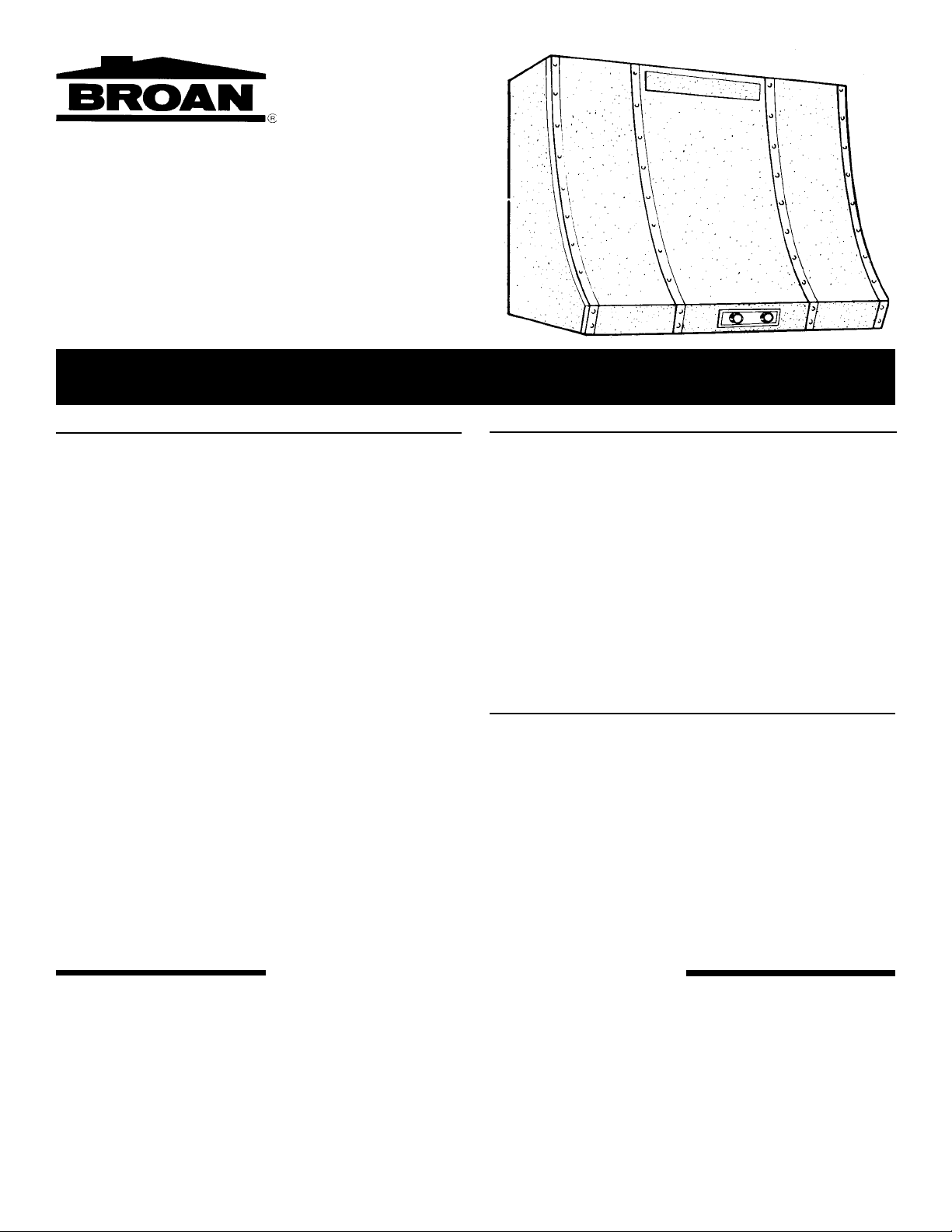
PLANNING THE DUCTWORK
Begin planning the ductwork by deciding where the duct will run
between the range hood and the outside. For best performance,
use the shortest possible duct run and a minimum number of elbows. There are several choices shown below.
NOTE: Shown are typical installations. For maximum efficiency,
use 3¾” x 10” rectangular duct. In more complex ducting situations, a ducted range hood can be converted to round duct by
means of a transition.
1. OUTSIDE WALL — If your range is located on an e xterior wall,
duct horizontally through the wall. This is the most economical
installation, and also offers top performance because the duct
run is so short that it offers practically no resistance. (Fig. A)
NOTE: If ducting directly off the bac k of the hood, special care
must be taken to make sure that the damper in the damper/
duct connector and the damper in the wall cap do not interfere
with each other when the hood is operating. This could result
in either inadequate air delivery or backdrafts. If this condition
exists, remove the hood damper flap. Sometimes, when using
a wall cap, it is easier to duct v ertically and then use an elbow .
2. THROUGH ATTIC — TO ROOF OR EAVE — This is usually
the most efficient and economical installation if the range is
located on an inside wall and there is attic space above. (Fig. B)
3. THROUGH SOFFIT — TO OUTSIDE WALL —
the best solution when the range is located on an inside wall in
a two story home. (Fig. C)
This is often
4. BETWEEN JOISTS — TO OUTSIDE WALL OR EAVE
5. WHEN “THERE’S NO WAY” — UNDER CEILING — TO OUT-
SIDE WALL — Suppose you can’t use (2) because you have
a two story home. You can’t use (3) because y ou hav e no soffit
or don’t want to take the old one out. The joists run the wrong
way for (4) or you don’t want to tear up your ceiling.
To duct to the outside, attach the duct under the ceiling and
cover it with a false wood beam or use other materials to camouflage the ductwork (Fig. F)
UNPACKING
Unpack the hood and check the contents. Along with the canopy,
you should have received:
• Plastic bag containing:
— Four No. 10AB x 1½ long sheet metal screws (for
mounting canopy to wall or soffit or for use with plastic
hollow wall anchors
— Four 5/16” washers
— Four plastic hollow wall anchors
— Two 1/4” black sheet metal screws (for attaching
damper/duct connector to canopy hood
• One aluminum filter
• Damper duct connector
2
Page 3
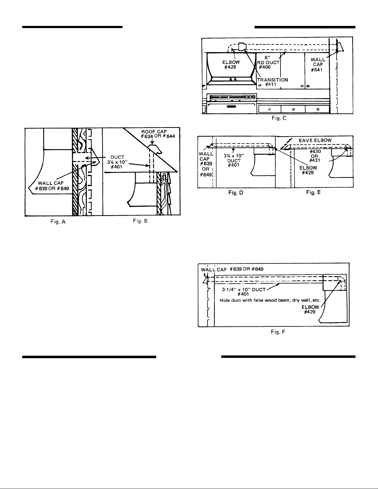
PREPARING THE RANGE HOOD
NOTE: To avoid motor bearing damage and/or noisy and unbalanced impellers keep drywall spray , construction dust, etc., off pow er
unit.
1. Remove sheet metal screw on outlet box cover and lift cover
out. (Fig. 1)
2. Remove proper electrical knockout according to whether you
will bring power to the hood from the soffit or the wall. (Fig. 2A)
4. Remove either the vertical or horizontal duct knockout,
according to whether you will duct the hood vertically or
horizontally. (Fig. 3)
Fig. 3
5. Install the damper/duct connector (Fig. 4)
Fig. 2A
3. Insert a screwdriver into the knockout slot and bend the knockout back and forth. You may have to use pliers to pull the loosened knockout free. (Fig. 2B)
Fig. 2B
Fig. 4
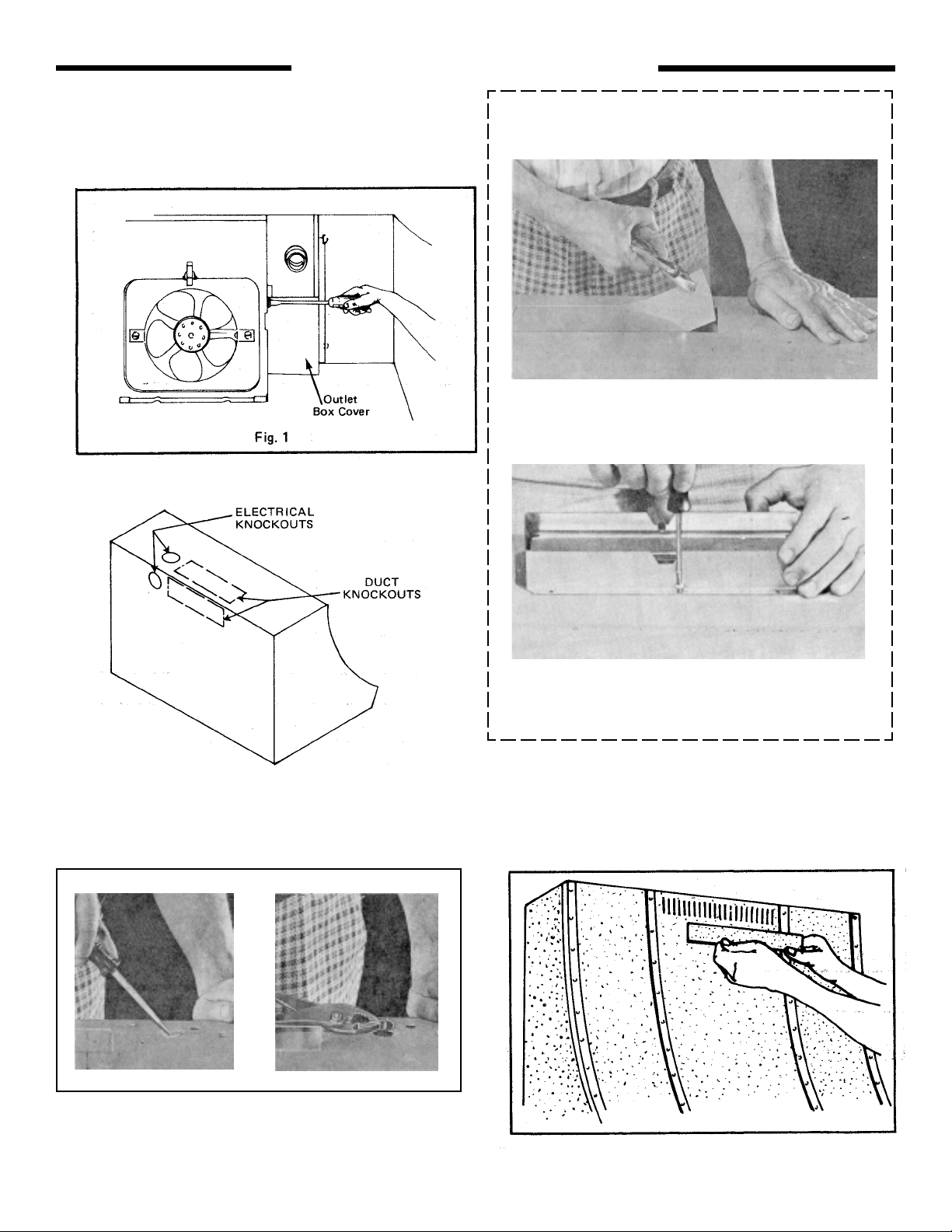
5. For ductfree installation only, remove louver co v er from
top front of hood. (FIG. 5)
Fig. 5
3
3
Page 4

PREPARING THE INSTALLATION LOCATION
NOTE
The range hood should be mounted so the bottom of the hood
is 18” to 24” above the cooking surface and the top front edge
of the hood should be flush with the front of the soffit.
7. Measure and mark the following (Figs. 6 & 7)
a. Electrical line opening.
b. duct opening in wall or soffit.
c. (For ventless installation only) Center hood in place
beneath soffit and flush with front of soffit. Trace
keyhole slots onto soffit.
8. Use a 1-1/4” drill bit to drill the opening for the electrical line. If
drilling in the wall, be carefull not ot cut existing cables. (Fig.
8).
NOTE:
Omit steps 9a through 9c for ventless installation.
9. Ducted installation only (Steps 9a - 9c
a. Measure and mark the duct opening in the soffit or
wall.
b. Drill four pilot holes in the corners of the marked
duct opening with a 1/2” wood bit, and with a saber
saw , cut out the opening in the wall or soffit. (Fig. 9).
c. Hold hood under the soffit and trace the keyhole
slots onto the soffit.
4
Page 5

PREPARING THE INSTALLATION LOCATION (CONT.)
10. Screw four supplied 1½” long screws (for mounting the hood)
into the exact center of the narrow end of the traced keyhole
mounting slots marked on the soffit. Do not turn the mounting
screws in all the way — allow 3/8” of screws to project, so that
hood can be fitted into place. (The screws will be tightened
later.)
For wall mounting, use the 1½” long screws into wall studs or
additional wall framing.
If wall studs or additional wall framing are not
available, follow these steps:
1. Drill a 5/16” diameter hole in wall material.
2. Fold anchor , insert anchor into hole, and tap
anchor flush with wall.
3. Push key into anchor to toggle anchor open
behind wall.
Do not hammer key!
4. Hold component in place over anchor. In-
sert screw and tighten until screw is flush
with component. Do not overtighten!
Wall material
5/16” dia. hole
é
é
é
Key
Component
Screw
INSTALLING THE DUCTWORK
NOTE
These instructions will follow the plans made on page 2. Start
at the exterior and run the ductwork back to the hood.
For best possible performance of your range hood, use the
shortest possible duct run and a minimum number of elbows.
Never vent a range hood into an attic space because a buildup of grease will become a fire hazard.
Use only metal ductwork (do not use plastic duct) Assemble
securely so that in case of fire on the range, the fire will be
contained inside the duct system.
Tape all duct connections to make them secure and airtight.
11. Follow the appropriate directions below for the type of ductwork
are installing.
a. To install a wall cap discharge (Fig. 11): Use a saber sa w or
keyhole saw to cut a hole slightly larger than duct size used
so that cap will line up easily with duct. Install casing strips
on the outside of a wood house if required. Run the required amount of ductwork back to the location of the hood
and trim the last section of ductwork so cap will be flush
with outside wall. Fasten wall cap to ductwork and nail or
screw cap to wall. Caulk all around flange with high quality
caulking compound.
Fig. 11
b. To install a roof cap: Cut a hole in roof slightly larger than
duct size being used. Run ductwork back to location of hood.
Leave approximately 3/4 ”for ductwork projecting above roof
surface on high side.
T rim ductwork parallel to roof pitch, and seal all around duct
with roof cement.
Carefully lift shingles and slide back of flange under shingles.
Nail flange to roof under shingles at top two corners and
two sides. Nail directly to roof in four places at bottom.
Using roof cement, seal all nail heads and shingles which
were cut or fitted. Do not scale bottom edge of flange. (Fig.
5
5
11)
Page 6

INSTALLING THE RANGE HOOD
SAFETY WARNING
Turn off the proper 120 volt circuit at the service entrance before
wirng the range hood.
12. Bring electrical cable through access hole drilled in the wall or
soffit. Split the cab le for 6” and install the proper connector for
the type of cable being used. Remove the lock nut from the
connector and let the prepared cable project through the soffit
or wall opening so it is ready for installation into the range hood.
(Fig. 12)
13. Position the hood in place so that:
a. The electrical line is routed through the appropriate knock-
out opening. This step will ha ve to be accomplished while
positioning the hood.
b. The damper/duct connector fits into the duct opening in
the soffit or wall.
14. Install loc k nut on the electrical connector and tighten securely .
15. Make the electrical connection using wire nuts to connect white
wire to white, black wire to black, and ground the hood to the
prepared hole using the green ground screw provided with the
hood. (Fig. 13)
16. Replace the wring box cover and screw. Make sure that all
wiring is contained safely inside.
17. Install 75 watt (R30) or 150 watt (R40) flood light. Ordinary
light bulb (100 watt max.) may also be used. Turn on power
and check operation of fan and light.
OPERATING INSTRUCTIONS
SWITCHES
Right knob controls light.
Left knob controls blower . Rotate knob CLOCKWISE to turn blow er
ON to HIGH speed. Further CLOCKWISE rotation decreases blower
speed. Rotate knob fully COUNTERCLOCKWISE (past HIGH
speed) to turn fan OFF.
CLEANING
Finish - Keep your range hood clean using a mild detergent suit-
able for painted surfaces.
Aluminum filters should be cleaned frequently with a detergent so-
lution to avoid grease build up. They are also dishwasher safe.
Do not wash the ductfree filter. Replace it whenever the colored
material on the back becomes noticeably dirty or discolored. Filters should last twelve months with normal use.
FILTER REMOVAL
1. Turn filter retainer clip to one side. Lift out old filter and discard
it. For MICROTEK™ System II hoods, discard both the aluminum filter and the ductfree filter, if hood is equipped with both.
For other hoods equipped with aluminum and ductfree filters,
discard both filters and replace with MICROTEK™ System I
filter.
2. Place new MICROTEK™ System Filter under filter retainer clip.
Make sure that blue side of filter is next to f an b lade . Turn filter
clip so that clip holds filter in place.
Make sure that arrows on retainer clip point toward front and back
of hood.
MICROTEK™ System filters are not washable. Filter should last
up to twelve months with normal use. Replace filter whenever it
becomes noticeably dirty or discolored.
6
Page 7

OPERATING INSTRUCTIONS (CONT.)
TO REMOVE FAN ASSEMBLY
Be sure power is disconnected. Remove Filters. Remove the two
screws holding the motor bracket to the range hood and unplug the
fan assembly. Be careful not to allow fan assembly to drop when
the screws are removed. (Fig. 15).
HOW TO AVOID A COMMON RANGE-TOP GREASE FIRE
• Your range hood provides a protective barrier between the
cooking surface and the cabinets.
• Keep fan, filters and grease laden surfaces CLEAN according to instructions.
• Always turn hood ON when cooking at high heat to keep the
cooking area and the hood cooler.
• Use high heat settings only when necessary.
• Never leave cooking surface unattended. Boil-over causes
smoking and greasy spillovers that may ignite.
• Always use adequate-sized utensils.
• If preparing flaming foods, such as Cherries Jubilee, always
turn hood ON to HIGH to prevent a high heat situation which
can cause damage or fire.
HOW TO EXTINGUISH A COMMON RANGE-TOP
GREASE FIRE
• Never pick up a flaming pan. If dropped, flames can spread
quickly.
• DO NOT USE W ATER! A violent stream explosion may result.
Wet dishcloths or towels are also dangerous.
• Smother flames with a close fitting lid, cookie sheet or metal
tray.
• Flaming grease can also be extinguished with baking soda or
a multi-purpose dry chemical extinguisher.
• T urn off surf ace units - if you can do so without getting burned.
BROAN ONE YEAR LIMITED WARRANTY
Broan warrants to the original consumer purchaser of its products that such products will be free from defects in materials or
workmanship for a period of one year from the date of original purchase. THERE ARE NO OTHER WARRANTIES, EXPRESS OR
IMPLIED, INCLUDING, BUT NOT LIMITED TO, IMPLIED WARRANTIES OF MERCHANTABILITY OR FITNESS FOR A
PARTICULAR PURPOSE.
During this one-year period, Broan will, at its option, repair or replace, without charge, any product or part which is found to be
defective under normal use and service.
THIS WARRANTY DOES NOT EXTEND TO FLUORESCENT LAMP STARTERS AND TUBES. This warranty does not cover (a)
normal maintenance and service or (b) any products or parts which have been subject to misuse, negligence, accident, improper
maintenance or repair (other than by Broan), faulty installation or installation contrary to recommended installation instructions.
The duration of any implied warranty is limited to the one-year period as specified for the express warranty. Some states do not
allow limitation on how long an implied warranty lasts, so the above limitation may not apply to you.
BROAN’S OBLIGATION TO REPAIR OR REPLACE, AT BROAN’S OPTION, SHALL BE THE PURCHASER’S SOLE AND
EXCLUSIVE REMEDY UNDER THIS WARRANTY. BROAN SHALL NOT BE LIABLE FOR INCIDENTAL, CONSEQUENTIAL OR
SPECIAL DAMAGES ARISING OUT OF OR IN CONNECTION WITH PRODUCT USE OR PERFORMANCE. Some states do not
allow the exclusion or limitation of incidental or consequential damages, so the above limitation or exclusion may not apply to you.
This warranty gives you specific legal rights, and you may also have other rights, which vary from state to state. This warranty
supersedes all prior warranties.
To qualify for warranty service, you must (a) notify Broan at the address stated below or telephone: 1-800-637-1453, (b) give the
model number and part identification and (c) describe the nature of any defect in the product or part. At the time of requesting
warranty service, you must present evidence of the original purchase date.
Broan-NuTone LLC, 926 West State Street, Hartford, WI 53027 (1-800-637-1453)
7
Page 8

Service parts for the Broan 11000 Series Convertible range hood are shown (with part numbers) in Figure 16. List the hood
SERVICE PARTS
model number and the part numbers of all parts being ordered. Order parts from your local dealer or Broan Manufacturing.
KEY PART
NO. NUMBER DESCRIPTION
1 --------- Canopy
2 99090632 Nameplate
3 99260470 Nut for Light Switch
4 99260422 Nut for Motor Switch
5 99360115 Knob
6 99030132 Solid State Fan Switch
7 97005328 Light Switch
8 98005773 Aluminum Wiring Tubing
9 98004963 Switch Cover
10 97006931 Aluminum Filter
12 99420472 Filter Retaining Clip
14 99020248 Fan Blade
15 99260466 Lock Nut, 6-32*
16 99160304 Machine Screw, 10-24 x 3/8*
17 98005568 Motor Mounting Bracket
18 97011224 Motor Assembly (Includes Key Nos. 14, 15 & 17)
19 97006241 Motor Receptacle
20 99270423 Bulb Holder with Wires
21 98005619 Outlet Box Cover
22 99170245 Sheet Metal Screw, 8-18 x 3/8 Hex Head*
23 99100420 Foam Gasket for Vent Cover
24 98005629 Vent Cover - White
98005630 Vent Cover - Almond
98005631 Vent Cover - Golden Wheat
98005632 Vent Cover - Avocado
98005633 Vent Cover - Coffee
98005635 Vent Cover - Black
98009855 Vent Cover - Biscuit
25 97005544 Damper Assembly (Includes Key Nos. 25 & 26)
26 98005221 Damper Flap
27 99100379 Damper Bushing
** 97008257 Sheet Metal Nuts (contains 2 nuts)
*Standard Hardware. May be purchased locally.
**Not Illustrated.
Figure 16. 11000 Series Range Hood, Exploded View and Parts List
99041908E
 Loading...