

Page 1
1
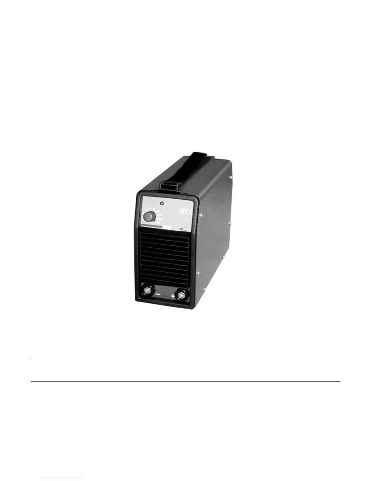
TG155 DC INVERTER TIG WELDING MACHINE
GB INSTRUCTION MANUAL FOR ARC WELDING MACHINE
Spare parts and wiring diagram - Page 11
Nu-TecSystems
4376 Lee Avenue
Gurnee, IL 60031
847-662-8500
800-554-0074
Page 2
2
INSTRUCTION MANUAL FOR ARC WELDING MACHINE
IMPORTANT
Before using this device all people authorised to its use, repair
or inspection, should read the book "Safety rules for using
machines" and the "Instruction manual" specific for every
machine. Contact your distributor if you have not understood
some instructions.
It is also essential to pay special attention to the "SAFETY
RULES" Manual. The symbols next to certain paragraphs
indicate points requiring extra attention, practical advice or
simple information.
This MANUAL and the "SAFETY RULES" MANUAL must be
stored carefully in a place familiar to everyone involved in
using the machine. They must be consulted whenever doubts
arise and be kept for the entire lifespan of the machine; they
will also be used for ordering replacement parts.
IN CASE OF MALFUNCTIONS, REQUEST ASSISTANCE
FROM QUALIFIED PERSONNEL.
1 GENERAL DESCRIPTIONS
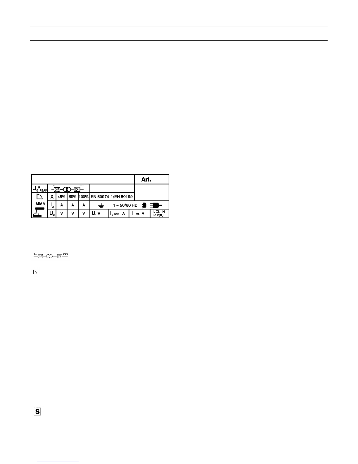
1.1 EXPLANATION OF TECHNICAL SPECIFICATIONS
EN 60974 - 1 The welder is manufactured acEN 50199 cording to this international standards
Art............................ Item number that must be stated for
any demands relating to the welding
machine.
.... Single-phase static frequency con-
verter - transformer - rectifier.
.......................... Dropping characteristic.
MMA....................…. Suitable for manual welding with coated
electrodes.
Uo............................. Secondary no - load voltage.
X.............................. Duty – cycle percentage.
The duty-cycle expresses the per-centage, calculated on 10
minutes, in which the welding machine
can operate at a determined current,
without over-heating.
I2.............................. Welding current.
U2............................. Secondary voltage with I2 welding
current.
U1............................. Nominal supply voltage.
1 ~ 50/60Hz............. Single - phase supply 50 or 60 Hz.
I1 max. …………….. This is the maximum value of the
absorbed current
I1 eff........................ This is the maximum value of the actual
current absorbed, considering the duty
cycle.
IP23C....................... Grade of protection of frame. Grade 3
as a second number means that this
unit is fit to work outside under the rain.
......................... Symbol meaning that the welding
machine can be used in high electric
shock risk-working areas.
NOTES:..................... In addition, the welding machine has
been designed to work in areas with
grade 3 of pollution.(See IEC 664).
1.2 SPECIFICATIONS
This welding machine is a constant direct current generator,
created by the INVERTER technology, designed for welding
with coated electrodes and with the TIG procedure.
For any requests of information, please always state the item
and the serial number of the welding machine.
1.3 BEFORE CONNECTING THE WELDING MACHINE
Before connecting and switching on the unit follow all safety
rules and instructions as indicated in this manual. Make sure
that the airflow on cooling slots is not obstructed and then
proceed as follows:
1) unpack the machine
2) take care that the unit is not placed against a wall or in a
position that might cut off the air; moreover, do not cover
the unit's source with plastic materials, metal or paper
sheets because they cause the decrease of the airflow,
3) make sure that the air temperature does not exceed +40°C,
4) do not place any filtering device over the intake air
passages of this welding machine.
Warranty is void if any type of filtering device is used.
2 INSTALLATION
2.1 CONNECTION TO MAINS SUPPLY
Before connecting the unit to the mains make sure that supply
voltage corresponds to the voltage indicated on the welding
machine technical specification tag.
2.2 PROTECTION SYSTEM
The unit is equipped with internal protections, which assure a
lasting proper operation.
These protective systems are the following:
2.2.1 Electrode anti-sticking protection
When the electrode sticks itself on the piece, the machine
brings the I2 current to not dangerous values for the electrode.
The signal light D (picture 1) indicates this operation.
2.2.2 Thermal protections
The signal light D (picture 1) indicates the intervention of this
protection. As soon as the unit has cooled down, it will be in
working conditions again.
OVER VOLTAGE CAN DAMAGE THE UNIT
2.2.3 Protection against incorrect supply voltages
If the voltage is greater than 270V when the switch (A pict. 1)
is turned on, the yellow led (D pict. 1) will flash briefly twice,
with a brief pause between flashes, and the machine will not
deliver current.
In this situation the electric circuits are protected, but the fan
may burn out after a few minutes.
In the voltage low during welding, the yellow led (D pict. 1)
flashes every 0.5 seconds and the machine does not deliver
current.
2.2.4 Motor-driven generators
These must have a power equal to or greater than 6kVA, and
must not deliver a voltage greater than 260V.
Page 3
3
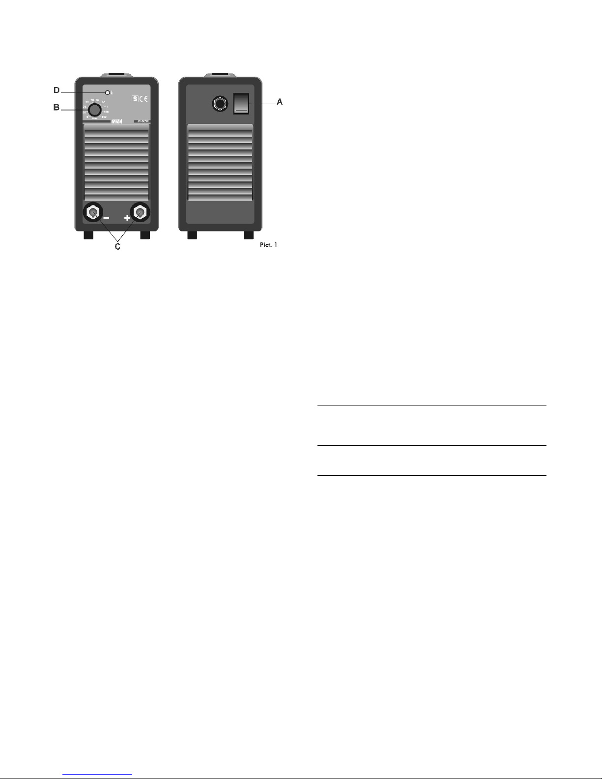
2.3 UNIT DESCRIPTION
A) Input voltage general switch.
B) Welding current adjustment potentiometer.
C) Texas connections.
D) Thermal and electrode anti-sticking protections signal.
2.4 GENERAL NOTES
Before using this welding machine, carefully read the
standards CEI 26/10 CENELEC HD 427 and also check
insulation of cables, electrode holder clamp, sockets and plugs
and that the section and length of welding cables are
compatible with current used:
up to 5 m use 16 mm2,
from 5 to 20 m use 25 mm2,
from 20 to 30 m use 35 mm2.
2.5 COATED ELECTRODE WELDING
- Use the electrode holder clamps in compliance with the
safety standards and without projecting tightening screws.
- Make sure that the switch A (picture 1) is in O position or that
the plug is not inserted in supply socket then connect welding
cables in accordance with polarity demanded by the
manufacturer of the electrodes which you will be using.
- Welding circuit should not be deliberately placed in direct or
indirect contact with protection wire if not in the piece to be
weld.
- If earthing is deliberately made on the workpiece by means
of the protection wire, the connection must be as direct as
possible, with the wire having a section at least equal to the
welding return current wire and connected to the piece,
being worked on, in the same place as the return wire, using
the return wire terminal or a second earth terminal close by.
- All possible precautions must be taken in order to avoid stray
currents.
- When taking voltage from a three-phase line, be very
careful when connecting the supply cable earth wire to
the socket earth pole.
- Connect the supply cable. When mounting a plug, make sure
that its capacity is adequate and that the yellow-green wire of
the supply cable is connected to the earth plug pin.
- The sections of all extensions should be adequate to
absorbed current I1.
- Turn the machine on by means of the switch A (picture 1).
WARNING: ELECTRIC SHOCK CAN KILL.
- Do not touch live electric parts.
- Do not touch weld output terminals when unit is energized.
- Do not touch electrode holder and earth clamp at the same
time.
- Adjust the current according to the diameter of the electrode,
to the welding position and to the type of joint to be carried
out.
When you have finished to weld, always remember to turn off
the unit and to remove the electrode from the electrode
holder.
2.6 TIG WELDING
- This welding machine is fit for welding with TIG procedure:
stainless steel, iron and copper.
- Connect the earth cable wire to the positive (+) pole of the
welding machine and the terminal to the working piece as
close as possible to the welding machine, making sure there
is a good electrical contact.
- Connect the connector of the TIG torch to the negative (-)
pole of the welding machine.
- The welding machine circuit should not be deliberately in
direct or indirect contact with protection conductor if not in the
piece to be welded.
- If earthing is deliberately made on the workpiece by means of
protection wire, the connection must be as direct as possible,
with the wire having a section at least equal to the welding
return current wire and connected to the piece being worked
on, in the same place as the return wire, using the return wire
terminal or a second earth terminal close by.
- All possible precautions must be taken in order to avoid stray
currents.
- Connect gas pipe to pressure reducer output connected to an
ARGON cylinder.
- Open the valve on the torch and regulate gas capacity.
- Use a 2% thoriated tungsten electrode chosen according to
table.
electrode ø direct current
2% thoriated tungsten negative electrode
(red band) (Argon)
ø 1 mm (0,040") up to 60A
ø 1,6 mm (1/16") 60 ÷ 160A
- Make sure that mains voltage corresponds to the voltage of
the welding machine.
- Connect the supply cable: when mounting a plug, make sure
that its capacity is adequate and that the yellow-green wire of
the supply cable is connected to the earth plug pin.
- Any extensions should have adequate sections for absorbed
current I1.
WARNING: ELECTRIC SHOCK CAN KILL!
- Do not touch live electric parts.
- Do not touch weld output terminals when unit is energized.
- Do not touch torch and earth clamp at the same time.
- Turn on the machine on with switch A (picture 1).
- Regulate current according to the work to be carried out, then
open the valve placed on the torch to allow the emission of
gas. Start the arc by contact, with a determined rapid
movement.
CAUTION: do not use commercial ignition devices.
When you have finished to weld, always remember to turn off
the machine and to close the gas cylinder valve.
Page 4
4
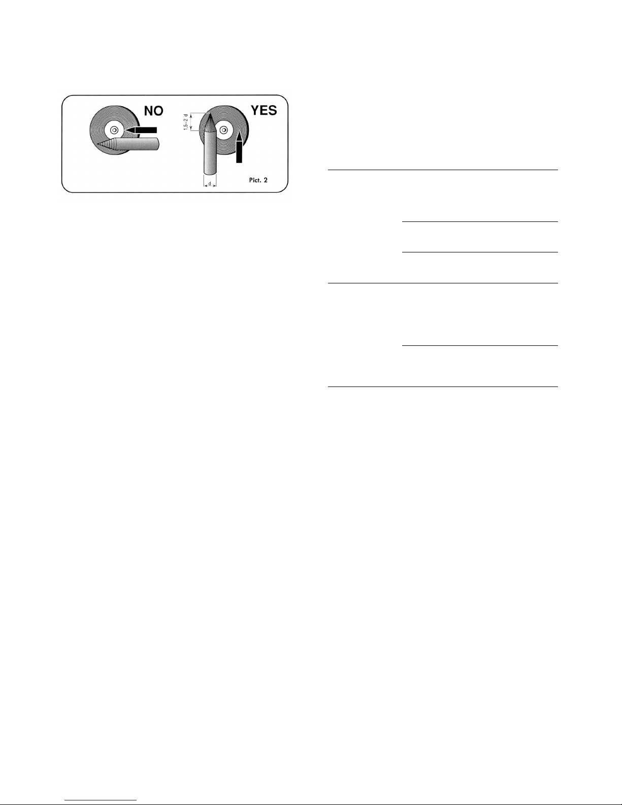
2.6.1 Electrode preparation
It is necessary to pay special attention to the preparation of the
electrode point, grinding it so as to obtain vertical markings as
shown in picture 2.
CAUTION: HOT FLYING METAL PARTICLES can injure
persons, start fires and damage equipment. TUNGSTEN
CONTAMINATION can lower the welding quality.
- Shape tungsten electrode only on grinder with proper guards
in a safe location, wearing proper face, hand, and body
protections.
- Shape tungsten electrodes on a fine grit, hard abrasive wheel
used only for tungsten shaping.
- Grind the end of the tungsten electrode to a taper-shape for a
length of 1,5 -2 electrode diameters (picture 2).
3 MAINTENANCE AND CHECK UP
3.1 GENERAL NOTES
WARNING: ELECTRIC SHOCK CAN KILL.
- Do not touch live electrical parts.
- Turn off welding power source and remove input power plug
from socket before maintenance and servicing.
MOVING PARTS can cause serious injury.
- Keep away from moving parts.
HOT SURFACES can cause severe burns.
- Allow the cooling of the unit before servicing.
3.2 WELDING MACHINE MAINTENANCE
Experience has shown that many fatal accidents originated
from servicing which had not been perfectly executed. For this
reason, a careful and thorough inspection on a serviced
welding machine is just as important as one carried out on a
new welding machine.
Furthermore, in this way manufacturer can be protected from
being held responsible for defects when the fault is someone
else.
3.2.1 Prescriptions to follow for servicing:
- After rewinding the transformer or the inductance, the welding
machine must pass the voltage test applied according to that
indicated in table 4 of the EN 60974-1.
- If no rewinding is done, a welding machine which has been
cleaned and/or reconditioned must pass a voltage test
applied with voltage values equal to 50% of the values given
in table 4 of EN 60974-1.
- After rewinding and/or the replacements of parts, the no-load
voltage should not exceed the values given in 11.1 of EN
60974-1.
- If the servicing is not done by the manufacturer, the repaired
welding machines which underwent replacements or
modifications of any component should be labelled in a way
such that the identity of the person having serviced is clear.
3.2.2 Precautions to take while servicing:
AN EXCESSIVE PRESSURE can break the circuit board.
Use only minimal pressure and gentle movements when
disconnecting or connecting board plugs and removing or
installing board.
INCORRECT INSTALLATION or misaligned plugs can damage
circuit boards.
Check that plugs are properly installed and aligned before
reinstalling the cover.
3.3 TROUBLE SHOOTING
DEFECT PROBABLE CAUSE REMEDY
The welding Switch in O position Switch to I
machine does not position
supply current;
completely
inoperative
Burnt fuses Replace
fuses
Plug not correctly Connect it
connected properly
_____
The welding Incorrect supply See 2.2.3
machine does voltage: yellow
not supply current signal lights up
but the ventilator
works
_____
Thermostat is open. Wait approx.
Yellow block signal 5-6 min.
lights up.
Page 5
5
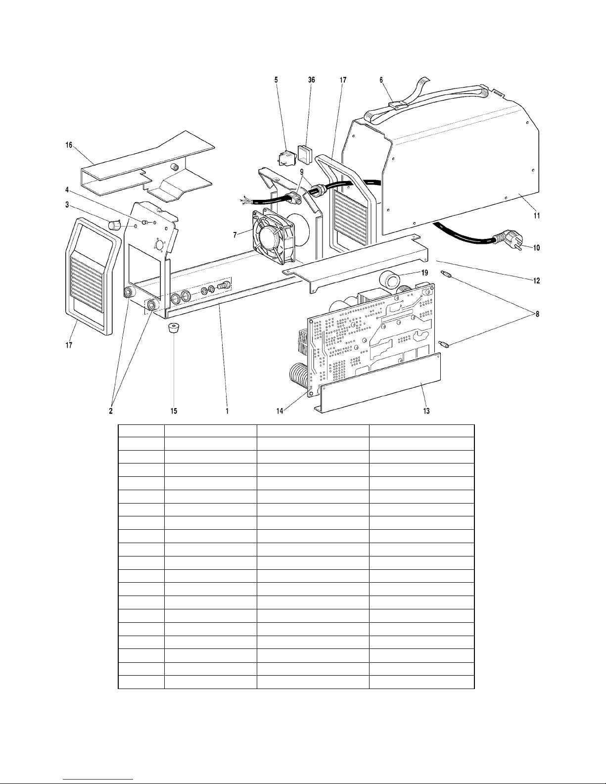
Item 135
Spare parts - Pièces de rechange - Piezas de repuesto
POS
DESCRIPTION
DESCRIPTION
DENOMINACION
1
PANEL
PANNEAU
PANEL
2
TEXAS CONNECTION
CONNEXION TEXAS
CONEXION TEXAS
3
KNOB
BOUTON
MANOPLA
4
LED HOLDER
SUPPORT LED
SOPORTE LED
5
SWITCH
INTERRUPTEUR
INTERRUPTOR
6
BELT
SANGLE
BANDA
7
FAN
VENTILATEUR
VENTILADOR
8
SPACER
ENTRETOISE
DISTÁNCIALE
9
STRAIN RELIEF
PRESSE-ETOUPE
PRENSA CABLE
10
SUPPLY INPUT CABLE
CABLE RESEAU
CABLE ALIMENTACION
11
HOUSING
CARROSSERIE
CARCASA
12
UPPER SUPPORT
SUPPORT SUPERIEUR
SOPORTE SUPERIOR
13
LOWER SUPPORT
SUPPORT INFERIEUR
SOPORTE INFERIOR
14
CIRCUIT
CIRCUIT
CIRCUITO
15
FOOT
SUPPORT
SOPORTE
16
COVER
COUVERTURE
COBERTURA
17
FRAME
CADRE
MARCO
19
FERRITE
FERRITE
FERRITA
36
SWITCH COVER
PROTECTION POUR INTERRUPTEUR
PROTECCION INTERRUPTOR
In case spare parts are required please always indicate: item ref. no. and purchase date of the machine, spare part position no. and quantity.
En cas de demande de pièces de rechange, toujours indiquer: l'article et la date d'achat de la mach ine, la position et la quantité des pièces.
Los pedidos de piezas de repuesto debe n indicar siempre: el numero de articulo y la fecha de adquisición del aparato, la posición y la cantidad de las piezas.
Page 6
6
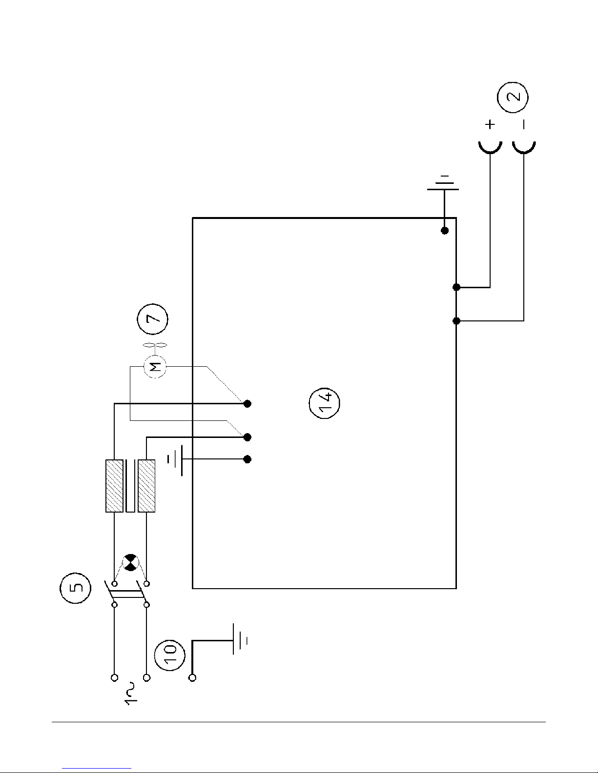
Item 135
Wiring diagram / Schéma électrique / Esquema eléctrico
 Loading...