


SPL 3200
Automotive lift date: 07/2000
Manual date: 07/2000
Operating instruction and documentation
s e r i a l - n u m b e r : . . . . . . . . . . . . . . . . . . . . . . . . . . . . . . . . . . . . . . . . . . . . . . . . . . . . . . . . . .
retailer addresse / phone
Nußbaum Hebetechnik GmbH & Co. KG || Korker Straße 24 || D-77694 Kehl-Bodersweier ||
Tel: +49 (0) 78 53/89 90 || Fax +49 (0) 78 53/87 87 ||
E-mail: info@nussbaum-lifts.de || http://www.nussbaum-lifts.de ||

Instruction and Documentation
SPL 3200
Table of contents
Record of Installation............................................................................................. 3
Record of handing over...........................................................................................4
1. Introduction........................................................................................ 5
2. Master Document of the automotive lift.......................................... 6
Attestation of conformity....................................................................................... 7
3. Technical Information........................................................................ 8
Data Sheet over floor..............................................................................................9
Foundation plan ..................................................................................................... 10
Electrical diagram drawing (standard version).......................................................11
Electrical clamped connection drawing..................................................................12
Electrical diagram drawing (single phase Canada version)....................................13
Electrical diagram drawing (three phase Canada version).....................................14
Electrical diagram drawing (single phase USA version)........................................15
Hydraulic diagram drawing.................................................................................... 16
4. Safety regulations............................................................................... 17
5. Operating instructions....................................................................... 17
6. Troubleshooting...................................................................................19
Emergency lowering...............................................................................................20
Torn rope.................................................................................................................21
7. Maintenance........................................................................................ 22
8. Security check......................................................................................22
9. Installation and Initiation...................................................................23
Installation of the lift...............................................................................................23
Regulations for installation.....................................................................................23
Erection and doweling of the lift........................................................................... 23
Initiation..................................................................................................................26
Changing of the installation place.......................................................................... 26
Appendix
Document ”First security check before Installation”
Document ”Regular security check”
Document ”Extraordinary security check”
Spare parts list
2

Send this record, filled in and undersigned, to the
automotive manufacturer after the installation
Otto Nußbaum GmbH & Co.KG
Korker Straße 24
777694 Kehl-Bodersweier
Germany
Record of installation
Instruction and Documentation
SPL 3200
The automotive lift SPL 3200 with the
serial number.: ................................... was installed on .........................................................
at the firm........................................... a t . . . . . . . . . . . . . . . . . . . . . . . . . . . . . . . . . . . . . . . . . . . . . . . . . . . . . . . . . . . . . . . . . . . . . . . . . . . .
the safety was checked and the lift was startet.
The installation was effected from the operating authority / competent (please delete as applicable)
The safety of the automotive lift was checked from the competent before the initial operation
The operating authority attest the installation of the automotive lift, the competent attest the correct
initial operation.
.............................. ................................................ . . . . . . . . . . . . . . . . . . . . . . . . . . . . . . . . . . . . . . . . . . . . . . . . . . . . . . . . . . . . .
date name of the operating authority signature of the operating authority
.............................. ................................................ . . . . . . . . . . . . . . . . . . . . . . . . . . . . . . . . . . . . . . . . . . . . . . . . . . . . . . . . . . . . .
date name of the competent signature of the competent
3

Instruction and Documentation
SPL 3200
Record of handing over
The automotive lift SPL 3200 with the
serial number.: ................................... was installed on .........................................................
at the firm........................................... a t . . . . . . . . . . . . . . . . . . . . . . . . . . . . . . . . . . . . . . . . . . . . . . . . . . . . . . . . . . . . . . . . . . . . . . . . . . . .
the safety was checked and the lift was startet.
The persons below were introduced after the installation of the automotive lift. The introduction
was carried out from an erector of the lift-manufacturer or from a franchised dealer (competent).
.............................. ........................................................... . . . . . . . . . . . . . . . . . . . . . . . . . . . . . . . . . . . . . . . . . . . . . . . . .
date name signature
.............................. ........................................................... . . . . . . . . . . . . . . . . . . . . . . . . . . . . . . . . . . . . . . . . . . . . . . . . .
date name signature
.............................. ........................................................... . . . . . . . . . . . . . . . . . . . . . . . . . . . . . . . . . . . . . . . . . . . . . . . . .
date name signature
.............................. ........................................................... . . . . . . . . . . . . . . . . . . . . . . . . . . . . . . . . . . . . . . . . . . . . . . . . .
date name signature
.............................. ........................................................... . . . . . . . . . . . . . . . . . . . . . . . . . . . . . . . . . . . . . . . . . . . . . . . . .
date name signature
.............................. ........................................................... . . . . . . . . . . . . . . . . . . . . . . . . . . . . . . . . . . . . . . . . . . . . . . . . .
date name of the competent signature of the competent
4

1 . I n t ro d u c t i o n
Instruction and Documentation
The document ”Operating Instructions and Documentation” contains important
infomation about installation, running and preserving of the automotive lift.
To furnish proof of installation of the automotive lift the form ”Record of Installation”
must be sent undersigned to the manufacturer.
To furnish proof of the single, regular and special security checks this documentation
contains forms. The forms should be used to document the checks. They should also be
left in this documentation.
Every Changes in the construction and changing place of the automotive lift must be
registered in the ”Master document” of the lift.
Installation and check of the automotive lift
Only specialist staff is allowed to do the works concerning safety and to hold the safety
checks of the lift. They are called experts and competents in this document.
Experts are persons (for example self-employed engineers, TÜV-experts) which have
got an instruction and experience to check and to test automotive lifts in an
e x p e r t ’s report. They know the signified regulations for protection of labour and
prevention of accidents.
Competents are persons which have got enough knowledge and experience with
automotive lifts. They took part in a training from the lift-manufacturer
(servicing erectors of the manufacturer and the franchised dealer are
Competents)
Information of danger
To show danger and to show important information the three symbols below with the
special meanings are used. Pay attention of those passages, which are marked with these
symbols
D a n g e r !
This sign marks a danger to life. Inexpert handling of the marked series of
event ist dangerous to life
C a u t i o n !
This sign marks a caution against possible damage of the automotive lift or
other material defects in case of inexpert handling .
I n d i c a t i o n !
This sign marks an indication for an important function or for another
important note.
5

Instruction and Documentation
SPL 3200
2 . Master document of the automotive lift
Lift designation SPL 3200
Lift-manufacturer Otto Nußbaum GmbH & Co.KG
Korker Straße 24
77694 Kehl-Bodersweier
Germany
Application
The automotive lift SPL 3200 is a lifting stage for lifting vehicles with a laden weight of
3200 kg and a max. load sharing of 2:1 in and against drive-on direction. The lift is
equipped for working under the load. It is not allowed to enter the load or to carry persons
with it.
Changes of construction, repairings and changes of place must be registered
in this master document
Changes of the construction, expert checking, resumption of work (date, kind of
change, signature of the expert)
. . . . . . . . . . . . . . . .
. . . . . . . . . . . . . . . .
. . . . . . . . . . .
...........................................................................................................................................
name, address of the expert
............................................................ .................................................................
place, date signature of the expert
Change of automotive-lift-place, expert checking, resumption of work (date, address
and signature of the competent)
...........................................................................................................................................
name, address of the competent
............................................................ .................................................................
place, date signature of the competent
6

Instruction and Documentation
SPL 3200
7

3 . Technical Information
Technical ratings
Lifting capacity: 3200 kg
Load sharing: max. 2:1 in or against drive-on
Lifting time: ca. 32 sec
Lowering time: ca. 41 sec
lifting capacity: 1740 mm
Line voltage: 3 x 400V, 50 Hz (standard)
Driving voltage: 220 V
Power rating: 3.0 kW (standard)
Instruction and Documentation
SPL 3200
direction
(observe the power supply of your state)
Motor speed: 2800 revolution/minute
Output oil-pump: 3 ccm/revolution
Hydraulic pressure: 185 bar
Responsing pressure of pressure relief valve: 215 bar
Hold-up oil tank: ca. 8 Liter
Sound level (measured at operating panel) ≤ 75 dBA
Safety devices
1. Ratchets
safety device of the load against unintentional lowering when the
hydraulic system isn’t tight any more
2. Screens at hydraulic cylinder
safety device for slow lowering in case of pipe breaking
3. Lockable main switch
safety device against unauthorized using
8

Data sheet
Instruction and Documentation
SPL 3200
command unit
9

Foundation plan
Instruction and Documentation
SPL 3200
1 0
Quality of the concrete B25

Instruction and Documentation
Electrical diagram drawing(standard version)
fuse
3xT 16 A
by customers
by customers
automotive lift
SPL 3200
Parts list for electrical diagram
A1: reversing switch for lifting
M1: motor 3,0 kW
F1: thermofuse in motor
K1: up contactor
A1, A2: clamped connections
1-6: clamped connections
U;V;W: clamped connections
1 1

Clamped connection drawing
Instruction and Documentation
SPL 3200
1 2

Instruction and Documentation
SPL 3200
Electrical diagram drawing (single phase Canada version)
1 3

Instruction and Documentation
SPL 3200
Electrical diagram drawing (Canada version 3 Phase)
1 4

Instruction and Documentation
Electrical diagram drawing (single phase USA)
SPL 3200
A1 main switch
M1 motor
1 5

Hydraulic diagram drawing
Instruction and Documentation
SPL 3200
Parts list of hydraulic diagram
0.1: oil-tank
0.2: motor
0.3: pump
0.4: oil-filter
0.5: oil-level gage
0.6: hydraulic block complete
0.7: holding valve
0.8: pressure relief valve
0.9: ball valve (lowering)
0.10: flow control holding valve
1.0: hydraulic cylinder
1 6
Instruction and Documentation
SPL 3200
4 . Safety r e g u l a t i o n s
Using automotive lifts for working the regulations of accident prevention EN1493/Aug.98
(CEN/TC 98“automotive lifts“ “european regulation“) must be observed.
Especially the following regulations are very important
• The laden weight of the lifted vehicle mustn’t be more than 3200 kg. The max. load
sharing is 2:1 in or against drive-on direction.
• During working with the lift the operating instructions must be followed.
• Only trained personnel over the age of 18 years old are to operate this lift.
• During lifting or lowering the vehicle it must be observed from the operator.
• It’s not allowed to stay under the lifted or lowered vehicle (except for the operator).
• It’s not allowed to transport passengers on the lift or in the vehicle.
• I t ’s not allowed to climb onto the lift during lifting or lowering or onto a lifted
vehicle.
• The Automotive Lift must be checked from an expert after changes in construction
or after repairing carrying pads.
• I t ’s not allowed to start with operations at the lift before the main switch is switched
off.
• Switching on or switching off the lift you have to take care that the lifting and
lowering movement are steady.
• It’s not allowed to install the standard-automotive lift in hazardous location.
5 . Operating instructions
The Safety Regulations must be observed during working with the automotive
lift. Read the safety regulations in chapter 4 carefully before working with the
lift!
The operating elements are shown in picture 1.
Lifting the vehicle with the SPL 3200
• Drive vehicle between the two columns, longitudinal directon and transverse
direction in centre.
• Safe the vehicle against rolling away, switch ino gear, activate parking brake
• Slew carrying arms under vehicle and position pads at the points which are provided
from the vehicle-manufacturer
• Control the dangerous places of the lift and be sure that there are no objects or
people in the immediate area of the lift or on the lift
• Turn operating (reversing) switch to position "↑" and hold position "↑" until the
wheels of the vehicle are free
1 7

Instruction and Documentation
SPL 3200
(front view)
(side view)
(side view)
pic. 1: operating elements
• When the wheels have been lifted free, stop with lifting; let go of operating
(reversing) switch and check safety sit of the pads under the vehicle.
The sit of the pads under the vehicle is very important. If the position
of the pads isn’t all right the vehicle might fall down!
Lifting great vehicles (transporter, cross country cars) pay attention that the roof
d o e s n ’t touch the traverse of the lift. In case the vehicle touches the traverse of
the lift, a switching off strip is pressed upside, which pulls the operating switch
via rod assembly to position ”0” , so the lift doesn’t lift any more. Afterwards the
operating switch can not be turned to position "↑"any more. However the lift can
still be lowered by pulling the operating lever (refer to ”lowering of the lift”).
After lowering the lift to the position where the switch off strip is free, the
operating switch is released and the lift can be lifted again.
• Lift vehicle on height for working; turn operating switch to position "↑", keep it
until height for working or top position is reached
1 8

Instruction and Documentation
SPL 3200
When the lift is lifted to top position the operating switchis pulled to
position ”0” with the help of a rod assembly. So lifting stops. Afterwards
the operating switch can not be turned to position "↑"any more. The lift
can only be lowered (as described in section ”lowering of the lift”). When
top position is left the operating switch is released and the lift can be lifted
again.
In case the operating switch is not pulled to position ”0” at top position
automaticly the ratchet -rope is slack or torn. Refer to chapter
”Troubleshooting” section ”torn rope”!
Lowering the vehicle with the automotive lift
• Control the dangerous places of the lift and be sure that there are no objects or
people in the immediate area of the lift or on the lift
• Lower the vehicle at the height for working or until the carrying arms reach the
lowest position; Pull operating lever ”lowering” (= lever left side) until height for
working or until lowest position.
Attention! while using lever ”lowering”, both levers (”lowering” and
”lowering in ratchet” will be activated!)
• When the lift is in lowest position, slew carrying arms inside and drive vehicle out
of the lift
Lowering the the automotive lift in ratchet
• Control the dangerous places of the lift and be sure that there are no objects or
people in the immediate area of the lift or on the lift
• Lower the vehicle in ratchet; pull operating lever ”lowering in ratchet” (= lever right
side).
Attention! Before going on with ”lowering” , lift the lift first a little bit
until the ratchet is not engaged any more, then go on with lowering!
6 . Tro u b l e s h o o t i n g
If the lift does not work properly, the reason for this might be quite simple. Please check
the lift for the potential reasons mentioned on the following pages. If the cause of
trouble cannot be found, please call the technical service.
Repairs at the lift’ s security devices as well as repairs and examinations of the
electrical fittings may only be performed by specialists.
1 9

Instruction and Documentation
SPL 3200
Problem: Motor does not start, lift is neither lifting nor lowering!
Potential causes • Fuse is defective: replace fuse
of trouble: • Feed line is cut
• Motor is overheated: let it cool down for app. 10 min.
Problem: Lift is not lifting!
Potential causes • Level of hydraulic oil is too low
of trouble: • In case of cold weather the hydraulic oil is too viscous
• ball-valve defective or dirty
• coupling between motor and pump is defective
• oil-filter in tank is dirty
• things (nuts, screws...) are in the columns and block the low lift
platform truck
• height limit switch is activated
Problem: lift cannot be lowered!
Potential causes • lift is driven onto an obstacle
of trouble: • equalisation ropes are too tight. Make sure that the ropes are fastened
(refer to capter ”Installation and Initiation”)
• Ratchets are engaged: move the lift up before lowering.
• In case of cold weather the hydraulic oil is too viscous
• ratchet-rope is torn; (refer to emergency lowering)
roblem: lift lowers by itself until the ratchet is engaged
Potential causes • holding valve isn’t tight or dirty
of trouble: • ball-valve is leck or dirty
Problem: lift is jerked while lowering
Potential causes • equalisation ropes are too tight, check course of the ropes
of trouble: (refer to ”installation and initiation”)
• air is in oil circulation;deaerate (refer to ”installation and initiation”)
Problem: operating (reversing) switch is not pulled back
mögliche Ursachen: • safety-rope is torn (refer to ”torn-rope”)
• safety-rope is slack (refer to ”torn-rope”)
Emergency lowering
If the ratchet-rope is torn the lift can not be lowered any more because one or two ratchets
are engaged. In this case there is the possibility to lower the lift by unlocking the ratchets
manually.
The emergency lowering must only be performed by persons instructed to use
the lift. Please refer to the regulation ”Lowering”.
2 0

Instruction and Documentation
SPL 3200
Emergency lowering
• In case the ratchets are engaged turn operating switch to position "↑", lift it a little
bit until the ratchets are unlocked.
• Let go of operating switch and lock it in position "0"
• Take off coverings from ratchets and look which of the ratchet-ropes is torn.
• Pull back the relevant ratchet and lay a suitable support between ratchet-strip and
ratchet or fix the pulled back ratchet with the help of a wire to avoid reengaging of
the ratchet-tooth in the ratchet-strip. This measure is to do at this ratchet where the
ratchet-rope is torn.
• Lower vehicle to lowest position (as described in chapter ”operating instructions”).
Refer to the regulations ”Lowering”
• Take off support or wire from ratchets that the can engage again.
To guarantee the safe running of the lift the supports must be removed
from the ratchet to bring the ratchet in its normal function
• After finishing with emergency lowering reinstall coverings.
• When the lift is in lowest position, slew carrying arms inside and drive vehicle out
of the lift
After finishing with emergency lowering the lift must shut down until the
defective ratchet has been replaced.
Torn rope
In case the safety-rope is torn the height limit switch and the switch off strip under the
traverse is witchout function. The lift must shut down until the defective rope has been
replaced. The new safety-rope must be installed as described in the following instruction.
• Disconnect power supply (disconnect feed line)
• Hang up safety-rope at topside (see pic. 5) and pull it through the empty rope
guidance tube
• Hang up safety-rope in boring of the flat rolled steel (backside at operating switch).
Turn operating switch to position "↑" and adjust length of the rope that the rope is
streched not too much.
Streching of the safety-rope: a small activation of the switch-rod or of the
switch-off strip must pull the operating switch to position ”0”.
• Connect power supply
In case the safety-rope in not torn, only slack, the rope must only be adjusted again after
disconnecting the lift from power supply
2 1

Instruction and Documentation
SPL 3200
7 . M a i n t e n a n c e
A regular service has to be performed every three months by the lift’ s operator
according to the following schedule. If the lift is in continuous operation or dirty
environment, the maintenance rate has to be increased.
During daily operation the lift has to be watched carefully for its correct function. In
case of any malfunction or leakage the technical service has to be informed.
Maintenance schedule for the lift
• Clean and grease all moving parts (pull-outs of the carrying arms, rollers of the
lifting carriage guidances, hinge bolts of carrying arms)
• Check rubber supports of pads. in case they are worn change them.
• control ratchets: easy and smooth latching, lubricate striking surfaces
• check level of hydraulic oil
• Check the ropes.
• Check the welding of thelift.
The hydraulic oil has to be changed at least once a year. To change the oil lower the lift
into its lowest position. Empty the tank and replace the oil, approximately 8 litres are
needed. A high quality hydraulic oil is recommended, its viscosity should be 32 cst.
8 . Security check
The security check is necessary to guarantee the safety of the lift during use. It has to be
performed in the following cases:
1. Before the initial operation, after the first installation.
Use the form ”First security check”.
2. In regular intervals after the initial operation, at least annually.
Use the form ”Regular security check”.
3. Every time the construction of that particular lift has been changed.
Use the form ”Extraordinary security check”.
The first and regular security checks must be performed by a competent. It is
recommended to service the lift at this occasion.
After the construction of the lift has been changed (changing the lifting height
or capacity for example) and after serious maintenance works (welding on
carrying parts) an extraordinary security check must be performed by an expert.
This manual contains form with a schedule for the security checks. Please use the
adequate form for the security checks. The form should remain in this manual after they
have been filled out.

Instruction and Documentation
9 . Installation and Initiation
Installation of the lift
Regulations for the installation
• The installation of the lift is performed by trained technicians of the manufacturer
or its distribution partner. If the operator can provide trained mechanics, he can
install the lift by himself. The installation has to be done according to this
regulation.
• The standard lift must not be installed in hazardous locations or washing areas.
• Installing the lift you need at least a reinforcement of 3,5 cm2/m Fe, quality B 25
(DIN 1045) in both directions at the upper and lower side of the plate. The thickness
of the carrying concrete should be at least 200 mm. In case of other foundation or
ground conditions a foundation according to foundation plan (refer to foundation
plan) has to be provided: An even installation place has to be provided. The
foundations must be based in a frost resistance depth, both outside and indoors,
where you must reckon with frost
SPL 3200
• An electric supply (observe the power supply of your state) has to be provided. The
supply must be protected by customers (fuses). The electrical connection is located
in command unit.
• All cable ducts have to be equipped with protective coverings to prevent accidents.
Erection and doweling of the lift
• Install the lift according to the data sheet and the foundation plan and line it up.
• Put both synchronizing ropes over the rolls at the top and insert them from the upper
side in column. The ropes must not be crossed!
• Connect hydraulic hose between the two columns. Don’t fix connection at opposite
side too tight and don’t fasten the connection. Be sure that hydraulic hose doesn’t
hinder the course of the synchronizing ropes.
• Put traverse topside on columns and fix it with enclosed cylinder screws and
washers
• Connect oil-return line (synthetic material) at both columns (see pic. 4)
• Check position of the lift
• Bore holes to fix the dowels through the borings of the base plates. Clean holes with
pressure air. Put in safety dowels with washers in borings. The manufacturer
demands LIEBIG safety dowels type B 20 or equal dowels of another manufacturer.
Before doweling check concrete floor with quality B 25 if the concrete floor goes to
the top edge of the floor. In this case the dowels have to be chosen according to
picture 2. If the ground is covered with floor tiles, the dowels have to be chosen
2 3

Instruction and Documentation
SPL 3200
according to picture 3.
• Check line-up of the columns and look if they are vertical. If they aren’t vertical
correct with suitable bases.
• Tighten the Liebig-dowels with a dynamometric key (M = 80 Nm).
Each Liebig-dowels must be tightened with a torque of 80 Nm. The normal
function of the lift cannnot be guaranteed (Liebig = german dowel
manufacturer).
• Connect power supply. The cable entry is at topside of operating column (standard
version).
• Fill oil-tank with oil: viscosity 32 cst, hold-up: approximatly 8 litre.
• pull ratchet back and lay a suitable support between ratchet strip and ratchet or fix
theratchet, which is pulled back with a wire, to avoid engaging of the ratchet tooth
in ratchet strip.
• Turn operating switch to position "↑": Only one side of the lift is lifted. Lift the lift
until oil comes out of the loosen threaded joint at topside of opposite column.
• Fasten threaded joint at top of opposite side.
• Load this carriage which has got a higher position (stand on it) and turn
simultaneously operating switch to position "↑". Only that carriage without load is
lifted. That carriage must be lifted until the carriage at the operating side is 10 cm
higher than the carriage at the opposite side.
• Dismount pulley at lower side in column (opposite side) by loosing the circlip. Lay
loosen synchronizing rope from topside round the pulley and remount pulley with
rope.
Secure pulley with washer and circlip while installing it.
• Insert synchronizing rope from lower side in ratchet strip which is fixed at lower
side of carriage. Insert thread bolt at end of the rope through bore-hole which is
located at hang up of the rope topside at ratchet strip.
• Screw self-locking nut approximatly 4 turns on thread bolt to fix the rope safely at
carriage.
• Load carriage of operating side (stand on it) and turn operating switch to position
"↑". Only the opposite side of the lift is liftet.
• Lift opposite side until carriage of operating side is lifted.
• Mount second rope in operating column as well.
• Fasten self-locking nuts at upper side in both carriages regulary until both ropes are
tighten lightly. If the thread at upper side of carriage is too short, the self-locking nut
at the other side carriage (lower side) must be fastened accordingly.
2 4

Instruction and Documentation
SPL 3200
• Lower automotive lift to lowest position and lift it afterwards 500 - 600 mm. Both
ropes must be tightened lightly. In any other case the self-locking nuts at the upper
side ob both carriages must be adjusted again.
Pay attention that each of the two ropes is tightened regulary and that it is
not too slack, otherwise exactly synchronization can not be guaranteed.
Pay attention that the ropes are not too tight, otherwise there is the
possibility that the lift jerks, or that the lift is too slow while lowering
The ropes don’t carry load. They must regulate an exactly synchronization
of the lift.
• Install carrying arms (refer to data sheet Power-Lift), lubricate bolts and secure
them with enclosured circlips at both ends.
The bolts of the carrying arms must be secured at both ends, otherwise a
safe connection between carriage and carrying arm can not be
guaranteed.
• Deaerating the lift: lower the lift to lowest position. loosen thread joint at lower side
of cylinder which must be deaerated. Lift the lift until oil comes out of the thread
joint. Now close the thread joint and fasten it.
In case the lift jerks while lowering there are two posibilities: the
synchronizing ropes are too tight or oil is in oil circulation (deaerate
according to instruction ahead)
• Loosen ratchet (now it the tooth of the ratchet can engage in ratchet strip again)
• Hang up long ratchet-rope with end nipple in ratchet at column of opposite side.
Take free end of the rope through rope-guidance tube to topside and afterwards take
it through the rope-guidance tubes at traverse and at column of operating side to
lower side again (see pic. 5).
• Mount thimble at end of the rope.
• Hang up ratchet-ropes with accompanying spring in operating lever ”lowering”;
operating lever is in initial position.
• The short ratchet-rope with end-nipple is already preassembled.
• Installing of the ratchet-ropes: Both ratchets mustn’t be engaged when operating
lever is completly pulled. The difference between backside of the ratchet and
column should be approximatly 60 mm (refer to pic. 6).
• For adjusting it might be necessary to loose one ratchet-rope and to strech the other
one to guarantee same position of both ratchets.
The ratchets must be free and their function must be guaranteed in any
case.

Instruction and Documentation
SPL 3200
Pay attention, that the ”switch-off covering” is smooth and that the lift is
switched off when the covering is pressed up. This covering is for
switching off the lift while lifting the lift the same time a vehicle drives
against it from upper side.
• Lift and lower the lift with vehicle several times, tighten dowels a second time (M
= 80 Nm).
Initiation
Before the initiation a security check must be performed. Therefore use form:
First security check.
If the lift is installed by a competent, he will perform this security check. If the operator
installs the lift by himself, he has to instruct a competent to perform the security check.
The competent confirms the faultless function of the lift in the installation record and
the form for the security check and allows the lift to be used.
Please send the filled installation record to the manufacturer after installation.
Changing of the installation place
If the place of installation shall be changed, the new place has to be prepared according
to the regulations of the first installation. The changing should be performed in accordance with the following points:
• lift carriage to medium height
• disconnect operating switch
• Take away current supply from lift
• Dismount carrying arms (remove circlips from carrying arm bolts, pull out carrying
arm bolts and take off carrying arm)
• Loosen long ratchet-rope
• Separate hydraulic connections between columns
• Dismount traverse support between the columns
• Empty oil-tank
• loosen dowels between base plate and floor and take off columns
• Transport lift to new installation place
• Install lift in accordance with chapter ”Installation and Initiation” of the lift.
Use new dowels, The used dowels cannot be used any more.
A security check must be performed before reinitiation by a competent. Use
form ”Regular security check”.

Instruction and Documentation
pic. 2: choice of dowel lengths (without floor pavement or tile surface)
SPL 3200
table to picture 5:
Liebig-safety dowels
type of dowel B20/175
Drilling depth a 225
min. anchorage depth b 1 7 0
thickness of concrete c 260
diameter of bor d 20
thickness of the Lift-piece e 0-65
You can use equivalent dowels from another manufacturer with licence, but observe their
regulations.
2 7

Instruction and Documentation
pic. 3: Choice of dowel lengths (with floor pavement or tile surface)
SPL 3200
table to picture 3:
type of dowel B20/175 B20/225
Drilling depth a 225 275
min. anchorage depth b 1 7 0 1 7 0
thickness of concrete c 260 260
diameter of bor d 20 20
thickness of the Lift-piece e+f 0-65 65-115
+ thickness of floor pavement
You can use equivalent dowels from another manufacturer with licence, but observe their
regulations.
2 8

pic. 4: course of the hoses
Instruction and Documentation
SPL 3200
return line hydraulic
service pipe
hydraulic
synchronizing
ropes
pulley
hydraulic cylinder
hang up of the rope
lower side carriage
hang up of the rope
upper side carriage
pulley
fixing at carriage
operating side
opposite side
2 9

pic. 5: ratchet-rope
Instruction and Documentation
SPL 3200
3 0
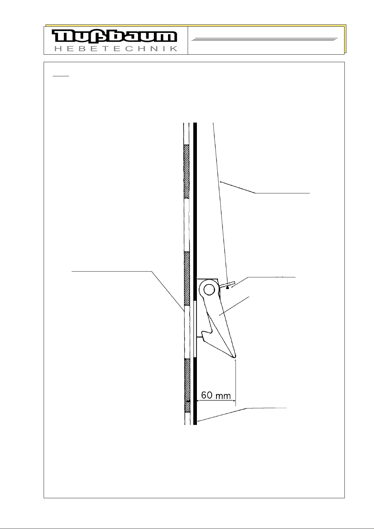
pic. 6: ratchet
Instruction and Documentation
SPL 3200
ratchet-rope
lifting carriage with
ratchet strip
end-nipple
ratchet
column
3 1

security check
SPL 3200
First security check before installation
kind of check
a l l
r i g h
d e f e c t
l a c k i n g
v e r i -
f i c a t i o n Remark
to fill in and to leave in
this document
Type plate ................................................... . . . . . . . . . . . . . . . . . . . . . . . . . . . . . . . . . . . . . . . . . . . . . . . .
Short operating instructions........................ . . . . . . . . . . . . . . . . . . . . . . . . . . . . . . . . . . . . . . . . . . . . . . . .
Warning designation................................... . . . . . . . . . . . . . . . . . . . . . . . . . . . . . . . . . . . . . . . . . . . . . . . .
Detailed operating instructions................... . . . . . . . . . . . . . . . . . . . . . . . . . . . . . . . . . . . . . . . . . . . . . . . .
Designation Lifting/Lowering .................... . . . . . . . . . . . . . . . . . . . . . . . . . . . . . . . . . . . . . . . . . . . . . . . .
Operating switch lockable........................... . . . . . . . . . . . . . . . . . . . . . . . . . . . . . . . . . . . . . . . . . . . . . . . .
Function limit switches ............................. . . . . . . . . . . . . . . . . . . . . . . . . . . . . . . . . . . . . . . . . . . . . . . .
Safety device hinge bolt ............................. . . . . . . . . . . . . . . . . . . . . . . . . . . . . . . . . . . . . . . . . . . . . . . . .
Security of pads .......................................... . . . . . . . . . . . . . . . . . . . . . . . . . . . . . . . . . . . . . . . . . . . . . . . .
Condition rubber support of pads .. ............ . . . . . . . . . . . . . . . . . . . . . . . . . . . . . . . . . . . . . . . . . . . . . . . .
Function fixing of carrying arms .. ............. . . . . . . . . . . . . . . . . . . . . . . . . . . . . . . . . . . . . . . . . . . . . . . . .
Construction (deformation, cracking) ....... . . . . . . . . . . . . . . . . . . . . . . . . . . . . . . . . . . . . . . . . . . . . . . . .
Fixed seat of the carrying screws ............... . . . . . . . . . . . . . . . . . . . . . . . . . . . . . . . . . . . . . . . . . . . . . . . .
Function, condition ratchet-system............. . . . . . . . . . . . . . . . . . . . . . . . . . . . . . . . . . . . . . . . . . . . . . . . .
guidance of carriage in column................... . . . . . . . . . . . . . . . . . . . . . . . . . . . . . . . . . . . . . . . . . . . . . . . .
Condition synchronizing rope, hang-up...... . . . . . . . . . . . . . . . . . . . . . . . . . . . . . . . . . . . . . . . . . . . . . . . .
Condition pulleys........................................ . . . . . . . . . . . . . . . . . . . . . . . . . . . . . . . . . . . . . . . . . . . . . . . .
Condition coverings ................................... . . . . . . . . . . . . . . . . . . . . . . . . . . . . . . . . . . . . . . . . . . . . . . . .
Condition hydraulic hoses........................... . . . . . . . . . . . . . . . . . . . . . . . . . . . . . . . . . . . . . . . . . . . . . . . .
Oil level gage.............................................. . . . . . . . . . . . . . . . . . . . . . . . . . . . . . . . . . . . . . . . . . . . . . . . .
Closeness of hydraulic system.................... . . . . . . . . . . . . . . . . . . . . . . . . . . . . . . . . . . . . . . . . . . . . . . . .
surface of piston-rod .................................. . . . . . . . . . . . . . . . . . . . . . . . . . . . . . . . . . . . . . . . . . . . . . . . .
Condition electrical wires, earth contactor... . . . . . . . . . . . . . . . . . . . . . . . . . . . . . . . . . . . . . . . . . . . . . . . .
Test: lift with vehicle ................................ . . . . . . . . . . . . . . . . . . . . . . . . . . . . . . . . . . . . . . . . . . . . . . . .
Condition concrete floor (cracks) ............... . . . . . . . . . . . . . . . . . . . . . . . . . . . . . . . . . . . . . . . . . . . . . . . .
( mark where applicable, in case of verification mark in addition to the first mark! )
security check carried out: .................................................................................................................
Name, address of the competent...........................................................................................................
Result of the Check:
Initation not permitted, verification necessary
Initation possible, repair failures until .............................................................
No failings, Initation possible
Signature of the expert:................................. Signature of the operator:..............................
If failures must be repaired
Failures repaired at: ...................................... Signature of the operator:..............................
( Use anather form for verification! )

security check
SPL 3200
Regular security check
a l l
r i g h t
d e f e c t
l a c k i n g
v e r i -
f i c a t i o n Remarkkind of check
to fill in and to leave in
this document
Type plate ................................................... . . . . . . . . . . . . . . . . . . . . . . . . . . . . . . . . . . . . . . . . . . . . . . . .
Short operating instructions........................ . . . . . . . . . . . . . . . . . . . . . . . . . . . . . . . . . . . . . . . . . . . . . . . .
Warning designation................................... . . . . . . . . . . . . . . . . . . . . . . . . . . . . . . . . . . . . . . . . . . . . . . . .
Detailed operating instructions................... . . . . . . . . . . . . . . . . . . . . . . . . . . . . . . . . . . . . . . . . . . . . . . . .
Designation Lifting/Lowering .................... . . . . . . . . . . . . . . . . . . . . . . . . . . . . . . . . . . . . . . . . . . . . . . . .
Operating switch lockable........................... . . . . . . . . . . . . . . . . . . . . . . . . . . . . . . . . . . . . . . . . . . . . . . . .
Function limit switches ............................. . . . . . . . . . . . . . . . . . . . . . . . . . . . . . . . . . . . . . . . . . . . . . . .
Safety device hinge bolt ............................. . . . . . . . . . . . . . . . . . . . . . . . . . . . . . . . . . . . . . . . . . . . . . . . .
Security of pads .......................................... . . . . . . . . . . . . . . . . . . . . . . . . . . . . . . . . . . . . . . . . . . . . . . . .
Condition rubber support of pads .. ............ . . . . . . . . . . . . . . . . . . . . . . . . . . . . . . . . . . . . . . . . . . . . . . . .
Function fixing of carrying arms .. ............. . . . . . . . . . . . . . . . . . . . . . . . . . . . . . . . . . . . . . . . . . . . . . . . .
Construction (deformation, cracking) ....... . . . . . . . . . . . . . . . . . . . . . . . . . . . . . . . . . . . . . . . . . . . . . . . .
Fixed seat of the carrying screws ............... . . . . . . . . . . . . . . . . . . . . . . . . . . . . . . . . . . . . . . . . . . . . . . . .
Function, condition ratchet-system............. . . . . . . . . . . . . . . . . . . . . . . . . . . . . . . . . . . . . . . . . . . . . . . . .
guidance of carriage in column................... . . . . . . . . . . . . . . . . . . . . . . . . . . . . . . . . . . . . . . . . . . . . . . . .
Condition synchronizing rope, hang-up...... . . . . . . . . . . . . . . . . . . . . . . . . . . . . . . . . . . . . . . . . . . . . . . . .
Condition pulleys........................................ . . . . . . . . . . . . . . . . . . . . . . . . . . . . . . . . . . . . . . . . . . . . . . . .
Condition coverings ................................... . . . . . . . . . . . . . . . . . . . . . . . . . . . . . . . . . . . . . . . . . . . . . . . .
Condition hydraulic hoses........................... . . . . . . . . . . . . . . . . . . . . . . . . . . . . . . . . . . . . . . . . . . . . . . . .
Oil level gage.............................................. . . . . . . . . . . . . . . . . . . . . . . . . . . . . . . . . . . . . . . . . . . . . . . . .
Closeness of hydraulic system.................... . . . . . . . . . . . . . . . . . . . . . . . . . . . . . . . . . . . . . . . . . . . . . . . .
surface of piston-rod .................................. . . . . . . . . . . . . . . . . . . . . . . . . . . . . . . . . . . . . . . . . . . . . . . . .
Condition electrical wires, earth contactor... . . . . . . . . . . . . . . . . . . . . . . . . . . . . . . . . . . . . . . . . . . . . . . . .
Test: lift with vehicle ................................ . . . . . . . . . . . . . . . . . . . . . . . . . . . . . . . . . . . . . . . . . . . . . . . .
Condition concrete floor (cracks) ............... . . . . . . . . . . . . . . . . . . . . . . . . . . . . . . . . . . . . . . . . . . . . . . . .
( mark where applicable, in case of verification mark in addition to the first mark! )
security check carried out: ...................................................................................................................
Name, address of the competent...........................................................................................................
Result of the Check:
Initation not permitted, verification necessary
Initation possible, repair failures until .............................................................
No failings, Initation possible
Signature of the expert:................................. Signature of the operator:..............................
If failures must be repaired
Failures repaired at: ...................................... Signature of the operator:..............................
( Use anather form for verification! )

security check
SPL 3200
Extraordinary security check
kind of check
a l l
r i g h t
d e f e c t
l a c k i n g
v e r i -
f i c a t i o n Remark
to fill in and to leave in
this document
Type plate ................................................... . . . . . . . . . . . . . . . . . . . . . . . . . . . . . . . . . . . . . . . . . . . . . . . .
Short operating instructions........................ . . . . . . . . . . . . . . . . . . . . . . . . . . . . . . . . . . . . . . . . . . . . . . . .
Warning designation................................... . . . . . . . . . . . . . . . . . . . . . . . . . . . . . . . . . . . . . . . . . . . . . . . .
Detailed operating instructions................... . . . . . . . . . . . . . . . . . . . . . . . . . . . . . . . . . . . . . . . . . . . . . . . .
Designation Lifting/Lowering .................... . . . . . . . . . . . . . . . . . . . . . . . . . . . . . . . . . . . . . . . . . . . . . . . .
Operating switch lockable........................... . . . . . . . . . . . . . . . . . . . . . . . . . . . . . . . . . . . . . . . . . . . . . . . .
Function limit switches ............................. . . . . . . . . . . . . . . . . . . . . . . . . . . . . . . . . . . . . . . . . . . . . . . .
Safety device hinge bolt ............................. . . . . . . . . . . . . . . . . . . . . . . . . . . . . . . . . . . . . . . . . . . . . . . . .
Security of pads .......................................... . . . . . . . . . . . . . . . . . . . . . . . . . . . . . . . . . . . . . . . . . . . . . . . .
Condition rubber support of pads .. ............ . . . . . . . . . . . . . . . . . . . . . . . . . . . . . . . . . . . . . . . . . . . . . . . .
Function fixing of carrying arms .. ............. . . . . . . . . . . . . . . . . . . . . . . . . . . . . . . . . . . . . . . . . . . . . . . . .
Construction (deformation, cracking) ....... . . . . . . . . . . . . . . . . . . . . . . . . . . . . . . . . . . . . . . . . . . . . . . . .
Fixed seat of the carrying screws ............... . . . . . . . . . . . . . . . . . . . . . . . . . . . . . . . . . . . . . . . . . . . . . . . .
Function, condition ratchet-system............. . . . . . . . . . . . . . . . . . . . . . . . . . . . . . . . . . . . . . . . . . . . . . . . .
guidance of carriage in column................... . . . . . . . . . . . . . . . . . . . . . . . . . . . . . . . . . . . . . . . . . . . . . . . .
Condition synchronizing rope, hang-up...... . . . . . . . . . . . . . . . . . . . . . . . . . . . . . . . . . . . . . . . . . . . . . . . .
Condition pulleys........................................ . . . . . . . . . . . . . . . . . . . . . . . . . . . . . . . . . . . . . . . . . . . . . . . .
Condition coverings ................................... . . . . . . . . . . . . . . . . . . . . . . . . . . . . . . . . . . . . . . . . . . . . . . . .
Condition hydraulic hoses........................... . . . . . . . . . . . . . . . . . . . . . . . . . . . . . . . . . . . . . . . . . . . . . . . .
Oil level gage.............................................. . . . . . . . . . . . . . . . . . . . . . . . . . . . . . . . . . . . . . . . . . . . . . . . .
Closeness of hydraulic system.................... . . . . . . . . . . . . . . . . . . . . . . . . . . . . . . . . . . . . . . . . . . . . . . . .
surface of piston-rod .................................. . . . . . . . . . . . . . . . . . . . . . . . . . . . . . . . . . . . . . . . . . . . . . . . .
Condition electrical wires, earth contactor... . . . . . . . . . . . . . . . . . . . . . . . . . . . . . . . . . . . . . . . . . . . . . . . .
Test: lift with vehicle ................................ . . . . . . . . . . . . . . . . . . . . . . . . . . . . . . . . . . . . . . . . . . . . . . . .
Condition concrete floor (cracks) ............... . . . . . . . . . . . . . . . . . . . . . . . . . . . . . . . . . . . . . . . . . . . . . . . .
( mark where applicable, in case of verification mark in addition to the first mark! )
security check carried out: ...................................................................................................................
Name, address of the competent...........................................................................................................
Result of the Check:
Initation not permitted, verification necessary
Initation possible, repair failures until .............................................................
No failings, Initation possible
Signature of the expert:................................. Signature of the operator:..............................
If failures must be repaired
Failures repaired at: ...................................... Signature of the operator:..............................
( Use anather form for verification! )
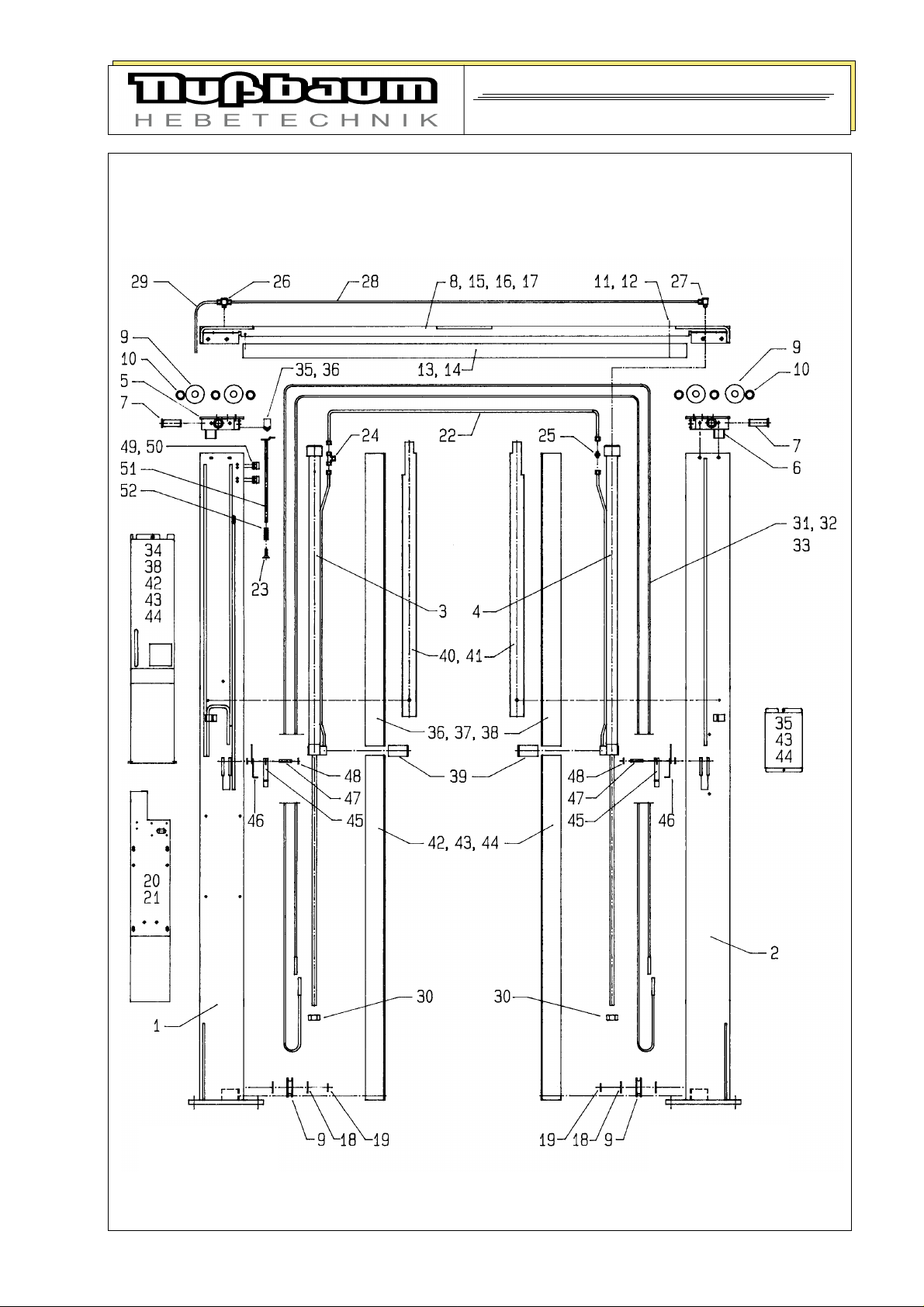
Spare parts list
SPL 3200
Spare parts list drawing: columns, coverings, cylinder, ropes
operating side
opposite side

Spare parts list
SPL 3200
Spare parts list drawing: columns, coverings, cylinder, ropes
Number Description Code
1 column operating side 235SPL05003
2 column opposite side 235SPL05039
3 hydraulic cylinder 232POW22003
4 hydraulic cylinder 232POW22002
5 head plate operating side 232POW25020
6 head plate opposite side 232POW25056
7 bolt of pulley 232POW05026
8 traverse 235SPL05074
9 pulley 232NSTL05063
10 distance bush 232NSTL05034D
11 cylinder screw 9Z912M10*110ZN
12 hexagon nut 9MU934M10ZN
13 switch off covering 232POW09016
14 pan-head screw 9F921M06*012ZN
15 hexagon head cap screw 9S933M10*020ZN
16 lock washer 9FR127M10ZN
17 hexagon head cap screw 9S933M10*016ZN
18 AS-washer 970022
19 Seeger circlip ring 9SR030*1.5
20 aggregate backside, welding piece 235SPL05092
21 countersunk screw 9S7991M08*16ZN
22 hydraulic tube 232POW01030
23 countersunk screw 9SE7991M08*12ZN
24 Male Stud branch Tee 980020
25 Male Stud coupling 980018
26 Male Stud branch Tee 960024
27 banjo elbow 960023
28 oil-return line 232POW01041
29 oil-return line 232POW01042
30 hexagon nut self-locking 9MU985M18*1.5ZN
31 set of control ropes 970405
32 hexagon nut self-locking 9MU985M12ZN
33 washer 9SC125M12ZN
34 covering 235SPL49024
35 covering of column opposite side 235SPL09020
36 covering of cylinder 235SPL09003
37 countersunk screw 9SE7991M05*12ZN
38 rosette 970010
39 cover band 232POW09006
40 cable cover 232POW09008

Spare parts list
SPL 3200
Spare parts list drawing: columns, coverings, cylinder, ropes
Number Description Code
41 hexagon nut 9MU934M06ZN
42 countersunk screw 9SE7991M05*08ZN
43 cylinder screw 9Z912M06*010ZN
44 lock washer 9FR7980M06ZN
45 ratchet 232SPL10003
46 leg spring 970251
47 bolt of bearing 232POW10008
48 Seeger circlip ring 9SR012*1
49 guidance 232POW10020
50 cylinder screw 9Z912M08*025ZN
51 switching-rod 232SPL10021
52 pressure spring 9DFD-187ZN

Spare parts list
SPL 3200
Spare parts list drawing: carriages, standard carrying arms

Spare parts list
SPL 3200
Spare parts list Power-Lift: carriage, carrying arms
Number Description Code
1 carriage, operating side 232POW06003
2 carriage, opposite side 232POW06039
3 sliding block topside 232POW06014
4 sliding block, lower side 232POW06015
5 sliding block bottom frontside 232POW06030
6 countersunk screw 9SE7991M06*20ZN
7 carrying arm (long) 232POW28003D
8 tooth lock washer 232NSTL08013
9 hinge bolt 232NSTL08016
10 shaft ring 970006
11 cylinder screw 9Z912M08*025ZN
12 carrying arm (short) 232POW28039
13 pad 232HEL08075
14 elastomer support 901103031
15 countersunk screw 9SE963M06*20ZN
16 hexagon nut 9MU934M06ZN
17 pull-handle 232NSTL08096
18 protecting cap 970008
19 compression spring 9DFD-222SLZN
20 heavy clamping sleeve 9SH1481DM03*16ZN

Spare parts list
SPL 3200
Spare parts list drawing: hydraulic-aggregate

Spare parts list
SPL 3200
Spare parts list: hydraulic-aggregate
Number Description Code
1 pump carrier 232POW21003
2 cylinder screw 9Z912M08*012ZN
3 lock washer 9FR7980M08ZN
4 countersunk screw 9SE7991M08*16
5 coupling 970290
6 pump 980243
7 cylinder scres 9Z912M08*085ZN
8 lock washer 9FR7980M08ZN
9 motor 3.0 KW (standard version) 990303
10 cylinder screw 9Z912M06*016ZN
11 lock washer 9FR7980M06ZN
12 cylinder screw 9Z912M08*016ZN
13 washer 9SC125M08ZN
14 Male Stud coupling 980135
15 Male Stud coupling 980014
16 suction pipe 232POW01028
17 hydraulic tube (pump to hydraulic block) 232POW01029
18 hydraulic tube (hydraulic block to T-piece) 232SPL01050
19 hydraulic tube(ball valve to hydraulic block) 232SPL01055
20 hydraulic tube (T-piece to cylinder) 232SPL01034
21 deaerate screw 980006
22 oil-filter 980201
23 Male Stud coupling 960025
24 ball valve 980512
operating lever 235SPL22033
25 hydraulic block complete 232SPL22037
26 hexagon nut 9MU934M08ZN
27 Adjustable Male Stud Run Tees 980071
28 pressure relief valve, complete 232NSTL02082
29 USIT-ring 980240
30 holding valve 980480
31 operating (reversing) switch (small) 990391
32 steel cord for operating switch 235SPL10014
33 steel cord for unlocking the ratchet 235SPL10012
34 steel cord for unlocking the ratchet 235SPL10013
35 luster terminal 990037
36 tension spring 9ZFZ-141ZN
37 tension spring 9ZFZ-092ZN
38 ratchet-lever 235SPL02020

Gebrauchsanweisung und
B Ü H N E N T Y P
4 2

Gebrauchsanweisung und
B Ü H N E N T Y P
4 3
 Loading...