

Page 1
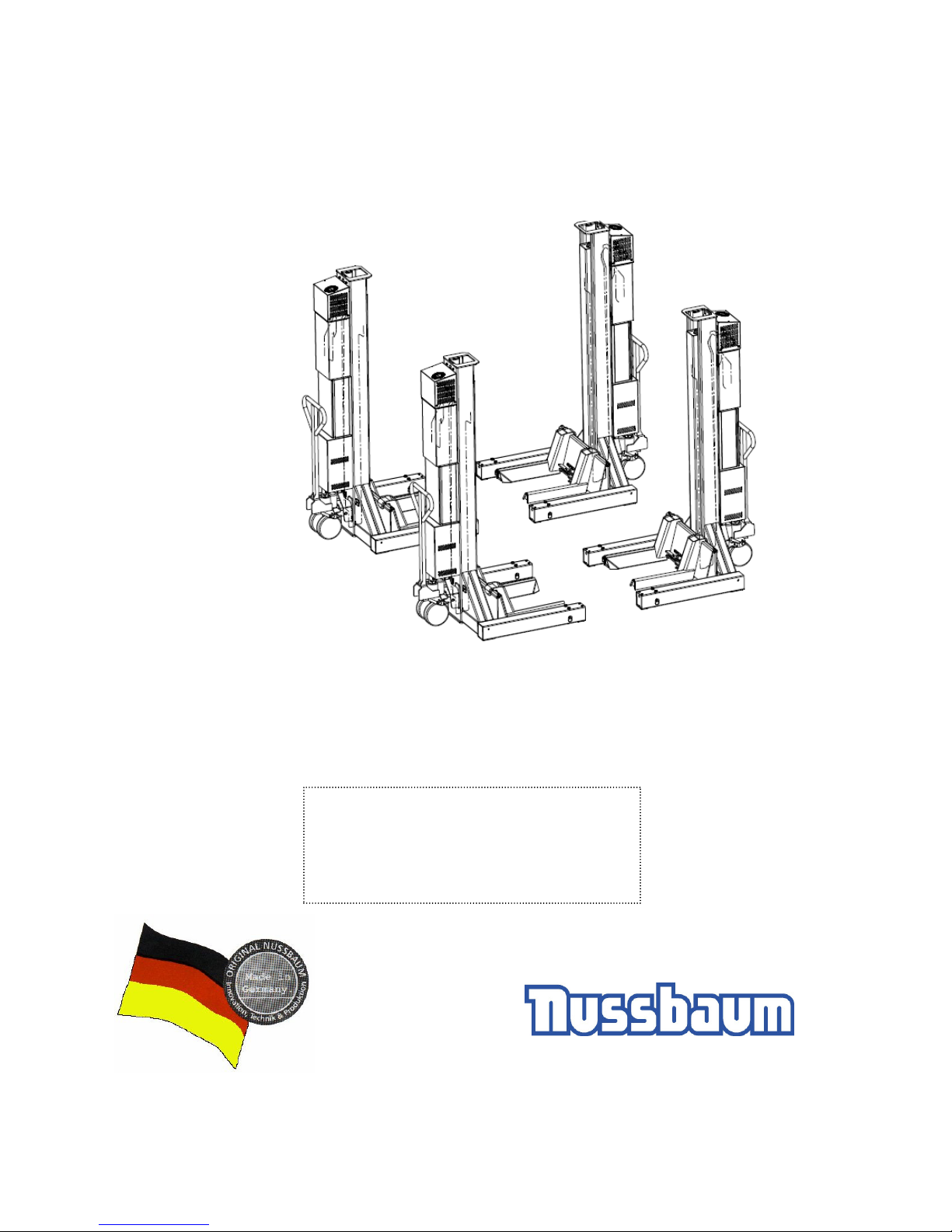
MCS 5500 ND WIRELESS
Date 2013 02 18
Operating Instruction and Documentation
Serial number:...........................................
Nußbaum Hebetechnik GmbH & Co.KG//Korker Straße 24//D-77694 Kehl-Bodersweier
Tel: +49(0)7853/8990 Fax: +49 (0)7853/ 8787//
E-mail:[email protected]//http://www.nussbaum-lifts.de
Retailer address / phone
Page 2

Operating Instruction and Documentation
MCS 5500 ND WIRELESS
- 2 -
Contents
Foreword ................................................................................................................. 3
Record of handing over ........................................................................................... 5
1.Introduction .............................................................................................................. 6
1.1 Installation and check of the automotive lift ....................................................... 6
1.2 Information of Warning ...................................................................................... 6
2.Master document of the MCS 5500 ND WIRELESS ............................................... 7
2.1 Lift–manufacturer ............................................................................................... 7
2.2 Application ......................................................................................................... 7
2.3 Changes at the construction .............................................................................. 7
2.4 Declaration of conformity ................................................................................... 8
3.Technical Information .............................................................................................. 9
3.1 Technical ratings................................................................................................ 9
3.2 Safety device ................................................................................................... 10
3.3 Data sheet ....................................................................................................... 11
4.Safety regulations .................................................................................................. 12
5.Operating instructions ............................................................................................ 14
5.1 Positioning of the columns ............................................................................... 14
5.2 Putting into operation ....................................................................................... 15
5.3 Lifting the vehicle (mode synchronous) ........................................................... 16
5.4 Lowering the vehicle (mode synchronous) ...................................................... 18
5.5 Single-Mode „Lifting“ ........................................................................................ 19
5.6 Single-Mode „Lowering“ ................................................................................... 20
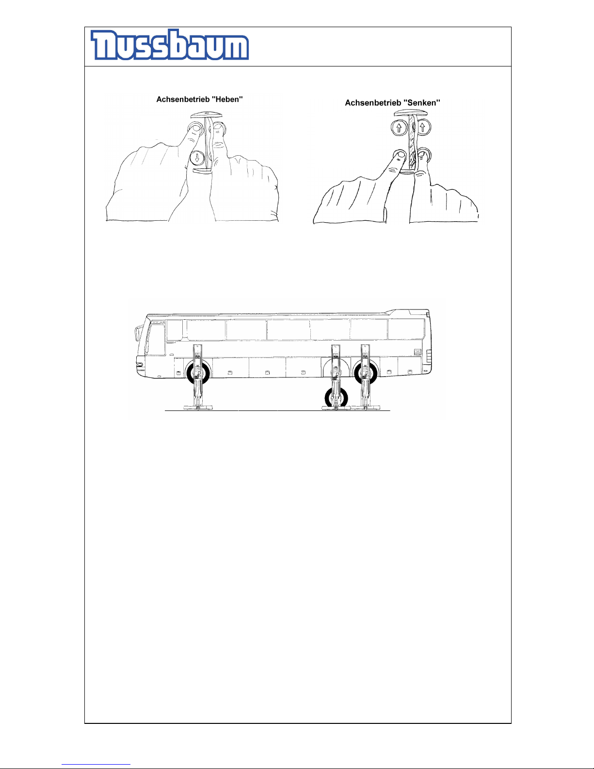
5.7 Axle-mode (only with 6 columns) ..................................................................... 21
5.8 Equalisation of the MCS .................................................................................. 22
6.Troubleshooting ..................................................................................................... 23
6.1 Lowering on a obstacle .................................................................................... 24
6.1.1 Remove the obstacle ................................................................................. 24
6.2 Emergency lowering ........................................................................................ 24
6.2.1 Procedure of the emergency lowering ....................................................... 24
6.3 Reset the MCS after an emergency lowering .................................................. 26
7.Inspection and Maintenance .................................................................................. 27
7.1 Maintenance plan of the Mobile column lift ...................................................... 27
7.2 Cleaning of the Mobile column lift .................................................................... 29
8.Security check ....................................................................................................... 30
9.Handing over and Initiation .................................................................................... 31
9.1 Regulations ...................................................................................................... 31
9.2 Initiation ........................................................................................................... 31
9.3 Position of the columns .................................................................................... 32
First security check before installation ................................................................... 33
Regular security check and Maintenance .............................................................. 34
Extraordinary security check .................................................................................. 42
Hydraulic diagram drawing .................................................................................... 43
Electrical diagram drawing ..................................................................................... 45
Page 3

Operating Instruction and Documentation
MCS 5500 ND WIRELESS
- 3 -
Foreword
Nußbaum-Lifts are a result of long-standing experiences.
The high quality and the superior concept guarantee them reliability, a long lift time and the
economic business.
To avoid unnecessary damages and dangers, read the operating instruction attentive and observe the
contents.
Another or the described purpose going out use is not valid when not as agreed.
This is valid particularly for climb and go.
Company Nußbaum is not liable for damages arising from this. The user carries the risk alonely.
For the use belonged:
- to observe all the notice in the operating instruction and
- the following of the inspection and maintenance work and the prescribed tests.
- The instruction for use have to be observed by all persons working with the lift.
- Especially the chapter “Safety/accident Prevention“ has to be observed.
- In addition to the safety remarks of the instructions for use the regulations and
instructions being valid at the place of operation have to be considered.
Obligations of the operator:
The operator is obliged to allow only those persons complying to the following requirement to work at
the unit
- being well acquainted with the basic regulations concerning labour safety and accident
prevention and being trained to operate the unit.
- having read and understood the chapter concerning safety and warning instructions and
confirmed that by their signature.
Dangers when operating with the lift:
The Nußbaum-Lifts are designed and built according to technical standard and the approved
regulations for technical security. Yet, danger for body and life of the operator may turn up when using
the lift inexpertly.
The lift must only be operated :
- for its appropriate use
- in unobjectionable condition concerning technical security.
Organising requirements
- The instructions for use are constantly to be kept at the place of operation being at hand
at any time.
- In addition to the instructions for use rules pertaining to other regulations i.e. accident
prevention and environmental rules are to be observed and directed.
- Safety- and danger alert operation of personal is occasionally and by observing the
instructions for use to be controlled.
Page 4

Operating Instruction and Documentation
MCS 5500 ND WIRELESS
- 4 -
- As far as required and ordered by regulations personal protective equipment is to be
used
- All safety- and danger-hints at the lift are to be observed!
- Spare parts must comply with technical requirements laid down by the manufacturer.
This is only warranted with original parts.
Consider time intervals given or fixed in instructions for use for repeated
tests/inspections.
Maintenanceworks, remedy of faults and disposal
- Fixed Adjusting-, maintenance- and inspectionworks and time intervals including
Details for exchange of parts/part components as mentioned in the instructions for use are to be
adhered.
These works must only be carried out by expert personal.
- After maintenance- and repair works loose screw connections must always be firmly
tightend!
Guarantee and liability
- Our „General conditions of selling and delivering“ are in force.
There will be no guarantee or liability for injuries of persons or things if these injuries are caused
by one or by some of the following reasons.
- Inappropriate use of the lift.
- Inappropriate installation, initiation, operation and maintenance of the lift.
- Use of the lift while one or several security devices do not work or do not work
correctly or are not installed correctly.
- Not to follow the regulations of the operating instruction concerning transport, storing,
installation, initiation, operation and maintenance of the lift.
- Changes of the construction of the lift without asking the producer.
- Changes of important adjustments of the lift (e.g. driving elements, power rating, motor speed,
etc)
- Wrong or incorrect maintenance.
- Catastrophes, acts of God or external reasons.
Page 5

Operating Instruction and Documentation
MCS 5500 ND WIRELESS
- 5 -
Record of handing over
The mobile column lift MCS 5500 ND WIRELESS with the
serial number:............................................ was installed on:...............................................
at the firm:................................................. at:.....................................................................
the safety was checked and the lift was started.
The persons below were introduced after the installation of the automotive lift. The introduction was
carried out from an erector of the lift-manufacturer or from a franchised dealer (competent person).
............................................ ..................................................... ............................................
date name signature
............................................ ..................................................... ............................................
date name signature
............................................ ..................................................... ............................................
date name signature
............................................ ..................................................... ............................................
date name signature
............................................ ..................................................... ............................................
date name signature
............................................ ..................................................... ............................................
date name signature
............................................ ..................................................... ............................................
date name of competent signature of the competent
Your customer service:...............................................................................................................
Page 6
Operating Instruction and Documentation
MCS 5500 ND WIRELESS
- 6 -
1.Introduction
The document ”Operating Instructions and Documentation” contains important information
about installation, operation and maintenance of the MCS 5500 ND WIRELESS.
To furnish proof of installation of the automotive lift the form ”Record of Installation” must be
signed and returned to the manufacturer.
To furnish proof of the singular, felt this documentation contains forms. The forms should be used
to document the checks. They should not be removed from this documentation.
Every Changes to the construction and displacement of the automotive lift must be registered in
the ”Master document” of the lift.
1.1 Installation and check of the automotive lift
Only specialist staff is allowed to do work concerning safety and to do the safety checks of the lift.
They are called experts and competent person in this document.
Experts are persons (for example self-employed engineers, experts) which have received
instruction and have experience to check and to test automotive lifts. They know the
relevant labour and accidents prevention regulations.
Competent person are persons who have acquired adequate knowledge and experience with
automotive lifts. They took part in training from the lift-manufacturer (servicing
technicians of the manufacturer or dealer, are competent)
1.2 Information of Warning
To show danger and to show important information the three symbols below are used. Pay
attention to those passages, which are marked with these symbols
Danger! This sign indicates danger to life. Inexpert handling of the described
operation may be dangerous to life.
Caution! This sign cautions against possible damage to the automotive lift or other
material defects in case of inexpert handling .
Attention! This sign indicates for an important function or other important notes.
Page 7

Operating Instruction and Documentation
MCS 5500 ND WIRELESS
- 7 -
2.Master document of the MCS 5500 ND WIRELESS
2.1 Lift–manufacturer
Otto Nußbaum Hebetechnik GmbH & Co. KG
Korker Straße 24
D-77694 Kehl-Bodersweier
Germany
2.2 Application
The mobile column lift is a lifting device for raising heavy vehicles (Truck, Bus...)
The maximum capacity of one mobile column lift amount 5500 kg / 12000lbs
It’s not allowed to install the standard-automotive lift in a hazardous location or washing bays.
2.3 Changes at the construction
Changes at the construction, expert checking, resumption of work (date, kind of change,
signature of the expert)
..............................................................................................................................................................
..............................................................................................................................................................
..............................................................................................................................................................
........................................................................................……………………………………...................
name, address of the expert
........................................................... ............................................................
place, date signature of the expert
Page 8
Operating Instruction and Documentation
MCS 5500 ND WIRELESS
- 8 -
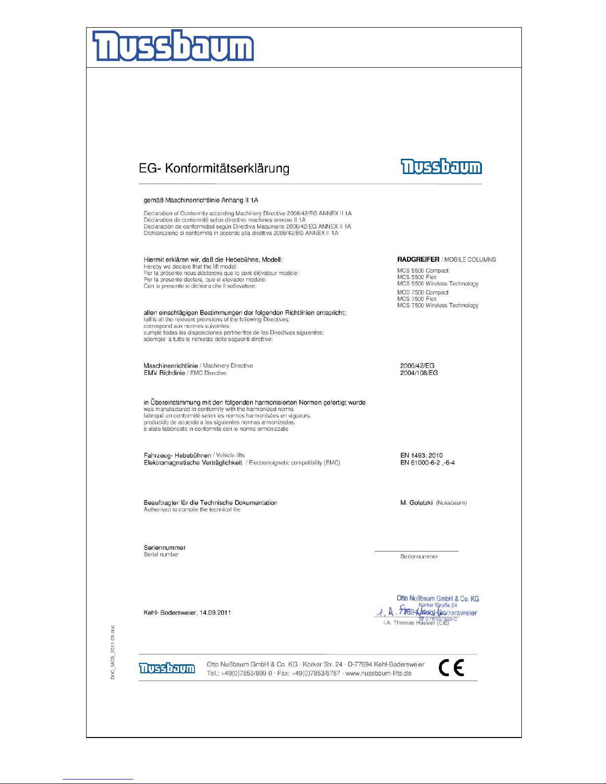
2.4 Declaration of conformity
Page 9

Operating Instruction and Documentation
MCS 5500 ND WIRELESS
- 9 -
3.Technical Information
3.1 Technical ratings
Capacity of one mobile column lift 5500 kg / 12000 lbs
Lifting time approx. 60 sec. with load
Lowering time approx. 65 sec. with load
Battery voltage 24V DC
Control rating 24 V
Power rating 2,1 kW
Motor speed 2600 rotation/min
Pump capacity 2,1 cm³/rotation
Hydraulic pressure approx. 220 bar with load
Pressure relief valve approx. 250 bar with load
Pressure relief valve (safety device) approx. max. 35 bar
Oil tank approx. 17 Liter
Sound level ≤ 75 dB(A)
Connection by customer (Battery charger) 110 / 220 V, 50 / 60 Hz
Fuse: mini 16 Ampere for 4 mobile column
(Pay attention to the tension of your state)
Page 10

Operating Instruction and Documentation
MCS 5500 ND WIRELESS
- 10 -
3.2 Safety device
1. Pressure relief valve
Overprint-safety of the hydraulic system
2. Holding valve
safety device against unintentional lowering
3. Lockable main switch
safety device against unauthorised operation
4. CE-STOP
Safety device against squeeze
5. Hydraulically unlocking safety-system at the cylinder
Safety device against unintentional lowering
6. Safety Star System (SST)
• The SST observed the complete Process of the Lift during „Lifting“ and „Lowering“.
• The lift will be lowering during the normal work with 0,028 Meter per sec.
If the lift descends noticeable faster there may be a problem with the hydraulic system. The
computer-control-system recognizes the problem and switch off the hydraulic supply for the
cylinder.
The Safety-star system locks and the lift stopped.
- Switch off the main switch.
- Check the complete hydraulic system. If the system is defective, call the service of your
retailer.
• The lift can be repaired by an expert, the satisfactory knowledge and experiences with
hydraulic lifts has.
CE-STOP
• The automotive lift stops automatically approx. 250 mm before the lowest position.
- Check the dangerous places of the lift and be sure that there are no objects or people in the
immediate area of the lift or on the lift.
- An acoustic signal is heard until the lift is in the lowest position
Top-Limit
• The Computer-control-system recognizes the top-height position of the lift and switch off.
Page 11
Operating Instruction and Documentation
MCS 5500 ND WIRELESS
- 11 -
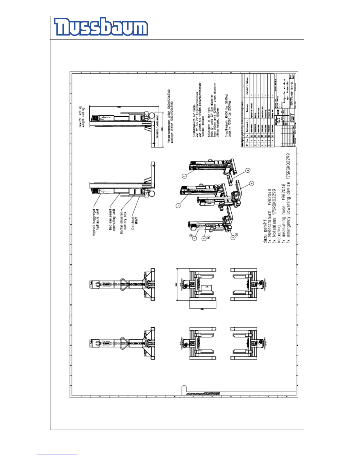
3.3 Data sheet
Page 12

Operating Instruction and Documentation
MCS 5500 ND WIRELESS
- 12 -
4.Safety regulations
• Read all instructions.
• The total weight of the lifted vehicle must not exceed the maximum capacity of the lift.
• Lower the lift completely before driving the vehicle into the lifting position.
• Use the lift only as described by the instructions in this manual.
• Before lifting low clearance, sport vehicles, vehicles with ground effects or running
boards, check carefully that no damage will occur before lifting.
• Only trained personnel 18 or older are allowed to operate the lift.
• The lift operator must observe the entire lifting and lowering process.
• Only the operator may remain under the lift while in use.
• Do not lift persons on the lift or in a vehicle on the lift.
• Do not climb onto the lift when raised.
• Keep hair, loose clothing, fingers, and all body parts away from the moving parts.
• Any changes or modifications to the lift must be checked by an expert (qualified service
person).
• To reduce the risk of shock the standard lift may not be installed in a hazardous (wet)
location.
• Power supply must be disconnected (main switch, plug, breaker) before any maintenance
is performed on the lift.
• Care must be taken as burns can occur from touching hot parts.
• Do not operate equipment with a damaged cord or if the equipment has been dropped or
damaged until it has be examined by a qualified service person (expert).
• To reduce the risk of fire, do not operate equipment in the vicinity of open containers of
flammable liquids (gasoline).
• ALWAYS WEAR SAFETY GLASSES. Everyday eyeglasses only have impact lenses,
they are not safety glasses.
• Adequate ventilation should be provided when working on operating internal combustion
engines.
• Do not let a cord hang over the edge of the table, bench, or counter or come in contact
with hot manifolds or moving fan blades.
• If an extension cord is necessary, a cord with a current rating equal to or more than that
of the equipment should be used. Cords rated for less current than the equipment may
overheat. Care should be taken to arrange the cord so that it will nor be tripped over or
pulled.
• Always unplug equipment from electrical outlet when not in use. Never use the cord to
pull the plug from the outlet. Grasp plug and pull to disconnect. Let equipment cool
completely before putting away. Loop cord loosely around equipment when storing.
• Vehicles with low clearance or vehicles that are specially equipped should be pre tested
to ensure that they clear the lift ramp to avoid damage.
• The mobile column lift must be checked from an expert after changes in construction.
• It’s not allowed to start with operations at the lift before the main switch is switched off.
• During lifting or lowering the operator must observe the vehicle to ensure that the vehicle
and the lift are functioning correctly.
Page 13

Operating Instruction and Documentation
MCS 5500 ND WIRELESS
- 13 -
• The main switch must be switched off and locked before work on the vehicle can
commence. This is a safety precaution to ensure that the lift does not move during work.
• Installation of the standard-mobile column lift in hazardous or dangerous locations such
as washing bays is dangerous and is not allowed.
• Check the center of gravity of the vehicle if heavy parts are removed. Secure the load
with suitable tools.
• Check the lift again, if the vehicle was raised 200 millimeter.
Page 14
Operating Instruction and Documentation
MCS 5500 ND WIRELESS
- 14 -
A
B
5.Operating instructions
The Safety Regulations must be observed during working with the automotive lift.
Read the safety regulations in chapter 4 carefully before working with the lift!
5.1 Positioning of the columns
• Every solid surface (concrete quality min C20/25) is suitable as installation-place.
•
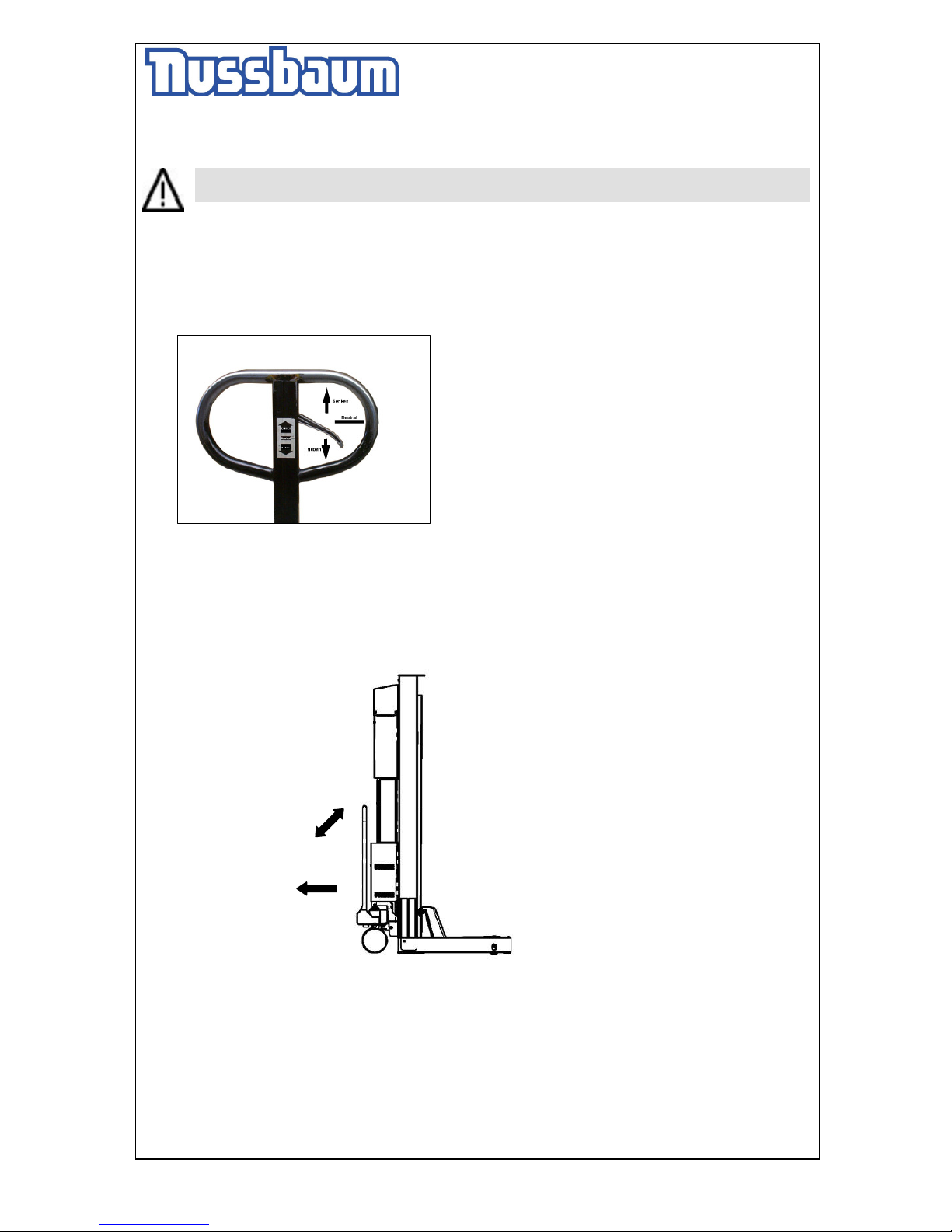
Push the lever from the „neutral“ position to the „lifting“ position.
pic 1: Hand lever
• A - Move the hand lever several times in arrow-direction = The mobile column lift raise.
• B – Drive the Mobile column lift to the wheel or remove it.
pic 2: Positioning the column lift
• Lower the Mobile column lift. Pull the lever slowly. (see pic. 1)
Page 15
Operating Instruction and Documentation
MCS 5500 ND WIRELESS
- 15 -
5.2 Putting into operation
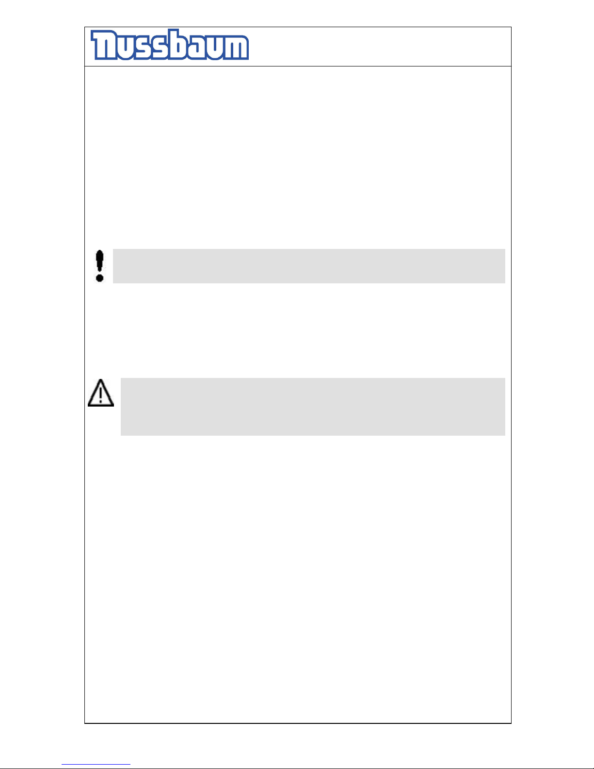
• Check the emergency stop buttons. All must be unlocked.
• Watch the bars of the battery charge control; the must be minimum at 60%. If not,
recharge battery first. (charger integrated in column, connect 230V, switch)
• If possible, FIRST put the system in operation and then enter the vehicle in vehicles area.
• To put the system in operation, first switch ON the mainswitch of all the 3 SLAVEcolumns. (SEE SLAVE-sticker on column). After switching ON the SLAVE, the display will
show “SLAVE”.
• After it, switch ON the main switch of the MASTER column (SEE MASTER-sticker on
column). The master is searching valid slave columns (about 50s).
• All 3 SLAVE-columns must be found by the MASTER .
In case of radio connection interruption(during operation) => switch SLAVES ON again,
afterwords switch MASTER ON again (see above : putting system in operation). If
connection is established again, operating the lift is possible again.
• Now drive vehicle in vehicles area .
• If all columns are in the lowest position, each display shows „0 mm“. If this is not the case,
press the button 2 “Lowering” (see pic. 4) until the carriage stops automatically. It is
possible, that nevertheless all columns are not yet in the lowest position.
Press the button 4 of the column, where you standing, and lower it in the lowest position.
It is important, that you press the lowering button, until all displays shows “0 mm”.
(Normally not by user : If not, open the electro-box of the concerned column. At the top
on the right side of the controller there are Dip-Switches. All beside the No. 5 are in the
same position. Check the positions of the carriage again, they must be in the lowest
position. Move the Dip-switch 7 two seconds to the left side and then back again. After it,
the display shows “0mm”. If necessary repeat this process at the other controllers.)
Page 16
Operating Instruction and Documentation
MCS 5500 ND WIRELESS
- 16 -
5.3 Lifting the vehicle (mode synchronous)
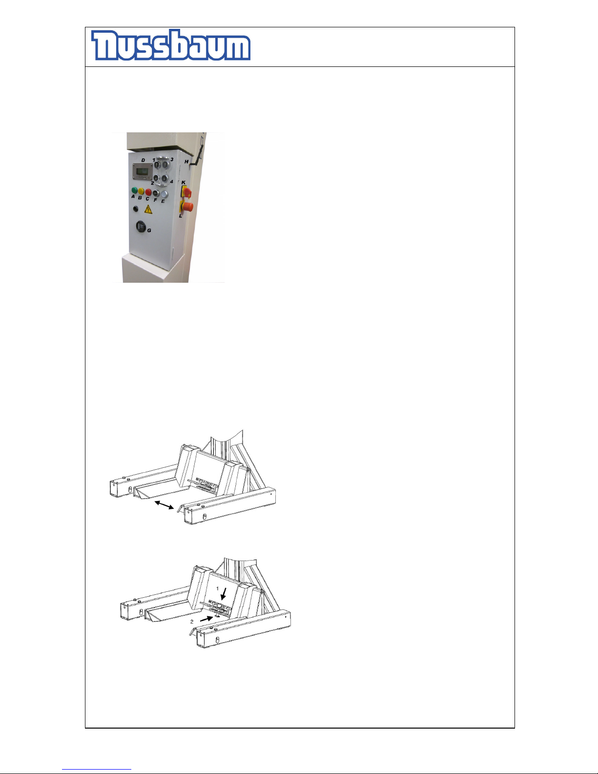
picture 3: operating unit
• Block the vehicle against rolling, put into gear.
• Position the Mobile column lift to the wheels and let it down with the hand lever. If
necessary use the additional supports.
1 : LIFTING (all columns)
2 : LOWERING (all columns)
3 : LIFTING (the column, at you are standing)
4 : LOWERING (the column, at you are standing)
A : LIGHT GREEN (columns in operation)
B : LIGHT YELLOW (Lifting / Lowering of two columns)
C : LIGHT RED (Failure)
D : LC-DISPLAY
E: PAIRED OPERATION
F: RELEASE BUTTON / REGISTRATION BUTTON
G: BATTERY CHARGE CONTROL
H: ANTENNA
K : MAIN SWITCH
L : EMERGENCY STOP BUTTON
pic 4:
Rim diameter 12“ –22“
Wheel diameter 450mm – 1250mm
pic 5:
secure the adjustable lifting arms with bolt and
clamp before working with the MCS
Page 17
Operating Instruction and Documentation
MCS 5500 ND WIRELESS
- 17 -
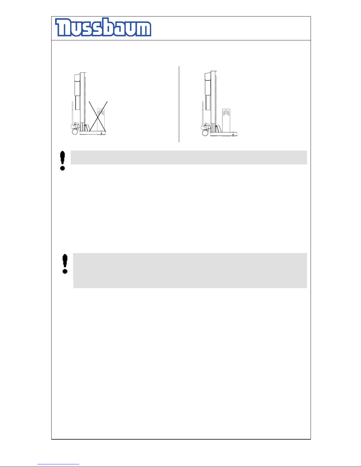
• Observe the position of the wheels in the mobile column lift (see pic. 6 and 7).
Before lifting the load, lower the mobile-column-lift in the lowest position (remove the
shaft), otherwise a malfunction can lead it to damages.
• Connect or disconnect the columns (observe the sketch) only if the main switch is
switched off. Otherwise a malfunction can be occur.
• Check the dangerous places of the lift and be sure that there are no objects or people in
the immediate area of the lift or on the lift.
• Switch on the control system; Switch-on the main switch on position ”1” .
• Raise the vehicle. Use all columns. Press the buttons „1-4”, at the operating unit.
If the column is active, the switches of the chosen columns, are lighten.
• Lift the vehicle on the working height. Press the button „lifting“ .
• In the display of the operating unit you can read the momentary height of the supports.
• Observe the complete process.
It is only allowed to lift or to lower the column lift with load. Otherwise a column lift
without load can cause an unequal. After it, this column lift switch-off the complete
system.
Accordingly, the number of the lifting wheels must agree with the number of the
column lift. Please, switch off the column, which do you not need.
wrong
Correct
pic. 6
pic. 7
Page 18
Operating Instruction and Documentation
MCS 5500 ND WIRELESS
- 18 -
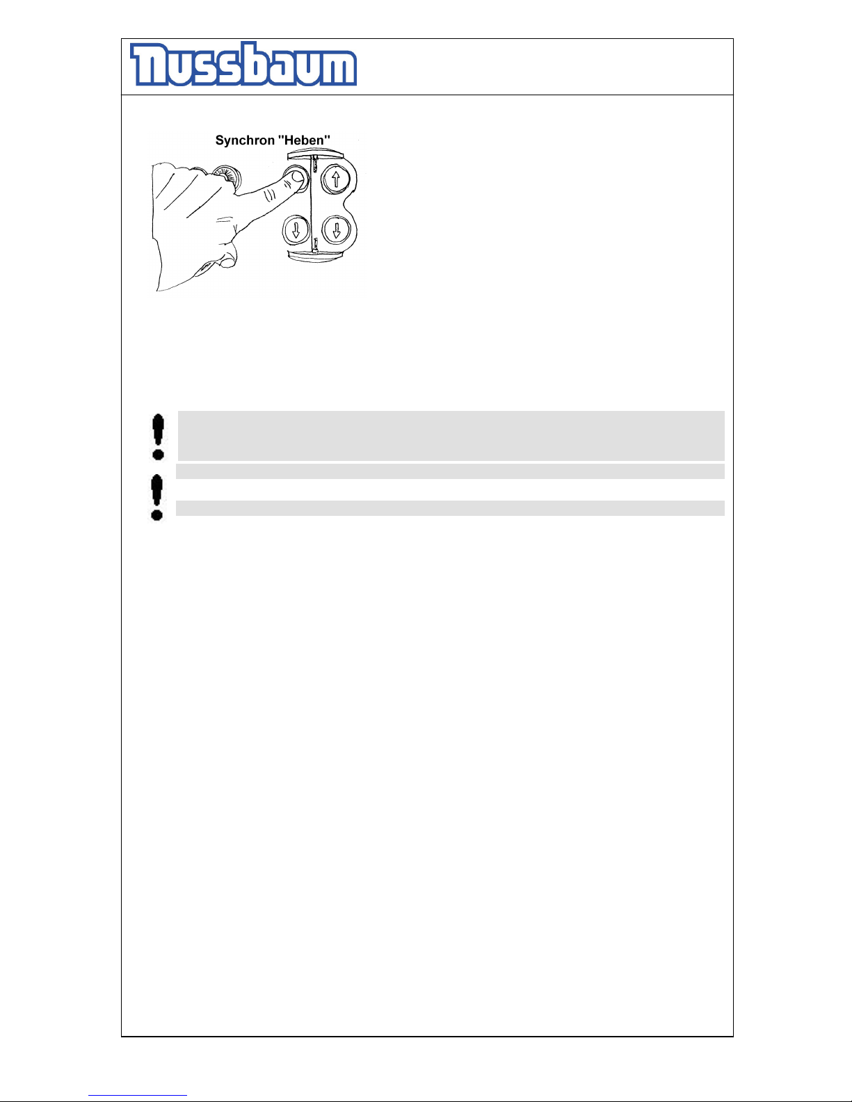
pic 7: Synchronous „lifting“
• Lift the vehicle on the working height. Press the button „lifting“ .
• In the display each MCS you can read the momentary height of the supports.
• Observe the complete process.
It is only allowed to lift or to lower the MCS with load. Otherwise a MCS without load
can cause an unequal. After it, this MCS switch-off the complete system and the red
light (disturbance) is lighting.
Accordingly, the number of the lifting wheels must agree with the number of the MCS.
In the case of disturbance, raise or lower the lift only in the „single“ mode.
5.4 Lowering the vehicle (mode synchronous)
• Check the dangerous places of the lift and be sure that there are no objects or people in
the immediate area of the lift or on the lift.
• Lower the lift at the height for working or in the lowest position.
Press the button „lowering“ (Synchronous) at the operating unit. The MCS raises a little
bit (unlocking the safety device), before the lowering starts.
• When lowering a vehicle, hold the button 2 pushed, until the lift has reached the height of
250mm; the lift stops automatically. Then push the button 2 again.
• The lift will continue in lowering. When a column stops during lowering between the
height of 0 and 250mm, use button 4 to lower all columns in single operation mode to the
ground (important for zeroing (referencing) the columns again). You hear an acoustic
signal until the lift reaches the lowest position.
In case of an SYNCHRON ERROR (shown on display; means unequal position error
of the columns) bring all columns back in the same position height, by using the
buttons 3 or 4 and watching the positions on the display. When all columns are at
the same height (position) again, you can operate the system in.
Page 19
Operating Instruction and Documentation
MCS 5500 ND WIRELESS
- 19 -
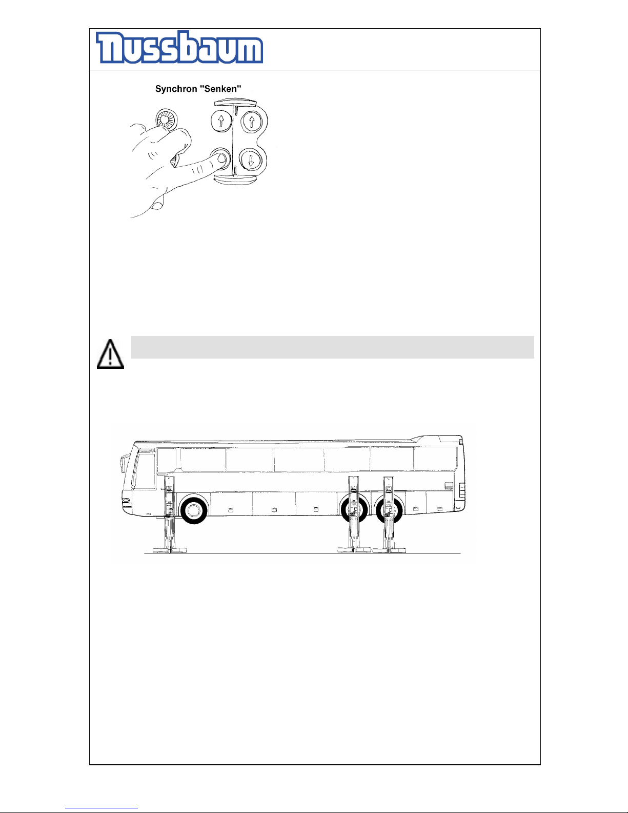
pic 8: Synchronous „lowering“
• Observe the complete process.
• When the lifts are in the lowest position the mobile lifts can be removed. Raise the MCS
with the hand lever (read chapter 5.1).
5.5 Single-Mode „Lifting“
Before dismounting heavy parts (motor, axle, set of gears) check the center of gravity.
Otherwise a malfunction can lead it to damages or leadto danger for body and lives.
It is possible to move the MCS in the single-mode. This is necessary to reach the
different levels of the pick-up points.
pic 9:
Through this measure, it is possible to raise the vehicle horizontally.
• Block the vehicle against rolling, put into gear.
• Position the MCS. Whenn necessary use the additional supports.
• Lower the MCS in the lowest position (with the handlever).
• Check the dangerous places of the lift and be sure that there are no objects or people in
the immediate area of the lift or on the lift.
• Switch on the control system; all the main switch on position ”1” .
• Raise every MCS with the single-mode until the pick-up points of the vehicle are reached.
Turn the plastic cover at the respective operating unit and press the button „lifting“
(single).
Page 20
Operating Instruction and Documentation
MCS 5500 ND WIRELESS
- 20 -
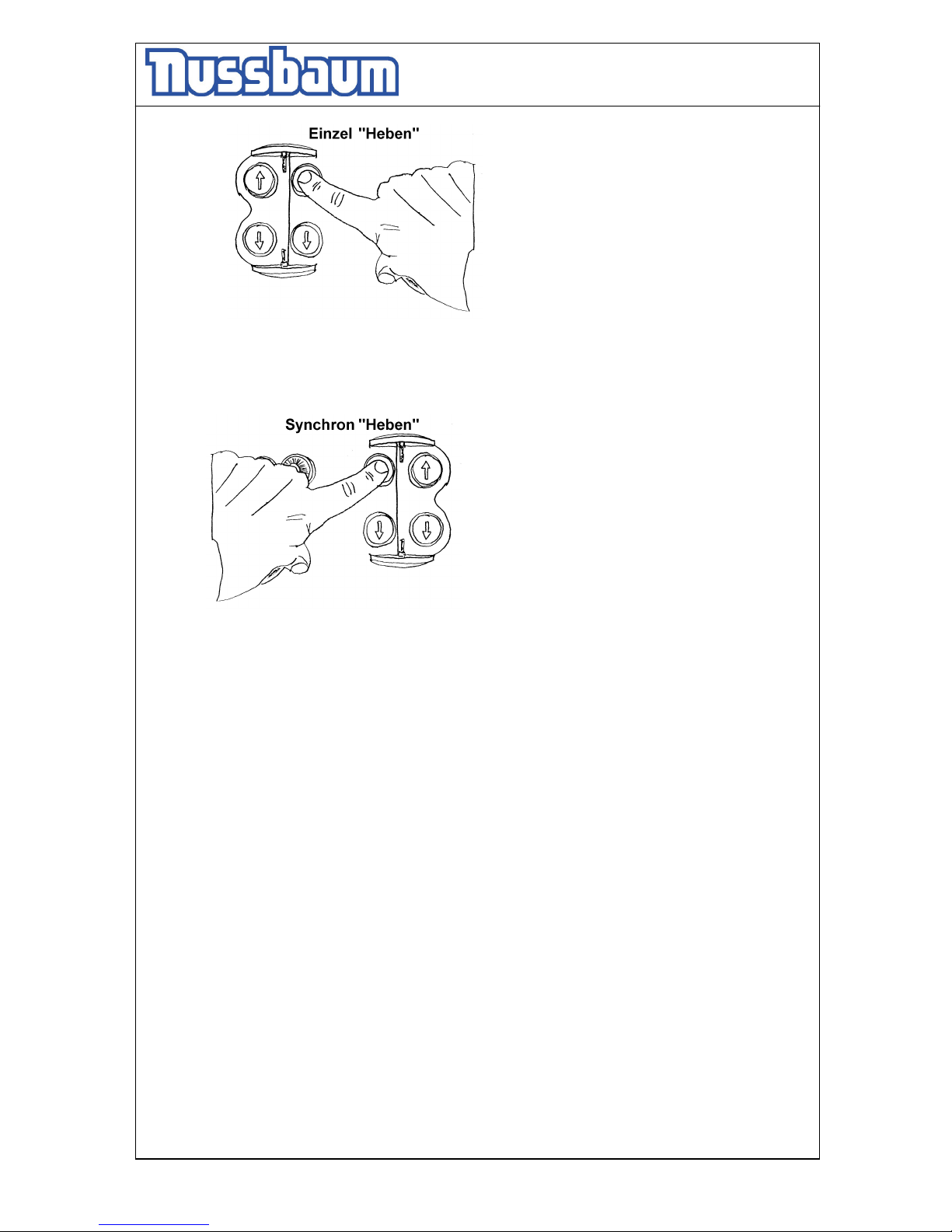
pic 10: single-mode “lifting”
• Now, all MCS are ready for the synchronous working.
• Raise the vehicle with the synchronous mode. Press the button „lifting“ (synchronous) at
one operating unit.
pic 11: synchronous mode “lifting”
• Lift the vehicle on the working height
• Observe the complete process.
5.6 Single-Mode „Lowering“
• Check the dangerous places of the lift and be sure that there are no objects or people in
the immediate area of the lift or on the lift.
• Lower the vehicle on the working height or the lowest position.
Press the button „lowering“ (synchronous see pic. 8) at the operating unit. The MCS
raises a little bit (unlocking the safety device), before the lowering starts.
• The mobile lift stops approx. 240 mm over the floor. Control the dangerous places of the
mobile lift and be sure that there are no objects or people in the immediate area of the lift
or on the lift. Press the button “ lowering” until the lift again. You hear an acoustic signal
until the lift reaches the lowest position.
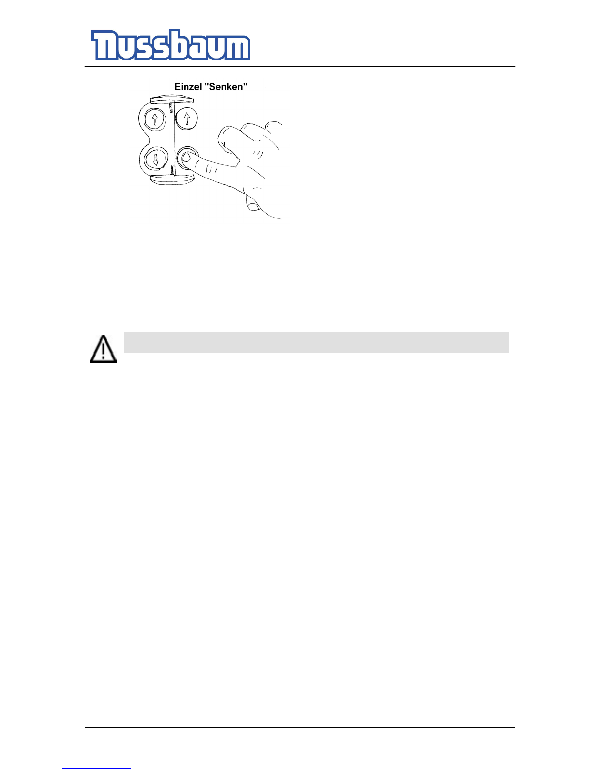
• The MCS which are standing on a higher level, lower with the “single-mode”. Turn the
plastic cover at the respective operating unit and press the button „lowering“ (single).
Page 21
Operating Instruction and Documentation
MCS 5500 ND WIRELESS
- 21 -
Bild 12: single-mode “lowering”
• Observe the complete process.
• When the lifts are in the lowest position the mobile lifts can be removed. Raise the MCS
with the hand lever (read chapter 5.1).
5.7 Axle-mode (only with 6 columns)
Before dismounting heavy parts (motor, axle, set of gears) check the center of gravity.
Otherwise a malfunction can lead it to damages or lead to danger for body and lives.
It is possible one MCS and the MCS at the opposite side to raise and to lower, together.
(axle-mode). This is necessary to dismounting heavy parts (motor, axle, set of gears.
Every MCS is equipped with photoelectric. (Transmitter and receiver)
• For using the axle-mode. The opposite MCS´s must become positioned , that the photo-
electric’s recognize itself.
• Select button paired operation (Button “E” at the operating unit) on both sides.
• For lowering of the singe axle, at you are standing: press button 2 and 4 together. The
columns towards each other will only move, when they get a signal from the opposite
column (photocell in the leg).
In case of radion connection interruption => switch SLAVES ON again, afterwords
switch MASTER ON again (see above : putting system in operation). If connection is
established again, operating the lift is possible again.
• The allowable maxi. deviation of both MCS to each other is allowed to ± 100 mm doesn't
overstep, otherwise the axis-mode is not possible.
The opposite MCS is recognized, the yellow signal lamp shines, when both buttons “Lifting
“ or both buttons “Lowering “ are pressed.
Page 22
Operating Instruction and Documentation
MCS 5500 ND WIRELESS
- 22 -
pic 14:axle-mode “lifting” pic 15: axle-mode “lowering”
The axle-mode is not possible (example: interrupt through an obstacle, deviation more than ± 100
mm) when the photoelectric are not recognized.
pic 16:
• Check the dangerous places of the lift and be sure that there are no objects or people in
the immediate area of the lift or on the lift.
• Lower the axle on the working height or the lowest position.
Press both buttons “lowering” at one operating unit of MCS, at you are standing. The
MCS raises a little bit (unlocking the safety device), before the lowering starts.
• Raise the vehicle on the working height.
• Observe the complete process.
• Raise the axle on the working height.
Press both buttons “lifting” at one operating unit of MCS, at you are standing.
5.8 Equalisation of the MCS
• The MCS are adjusting automatically during lifting and lowering.
First, lower the MCS always into the lowest position, this is the prerequisite for a trouble-
free work. In this position the complete system will be reset.
Page 23
Operating Instruction and Documentation
MCS 5500 ND WIRELESS
- 23 -
6.Troubleshooting
If the lift does not work properly, the reason for this might be quite simple. Please check
the lift for the potential reasons mentioned on the following pages. If the cause of
trouble cannot be found, please call the technical service.
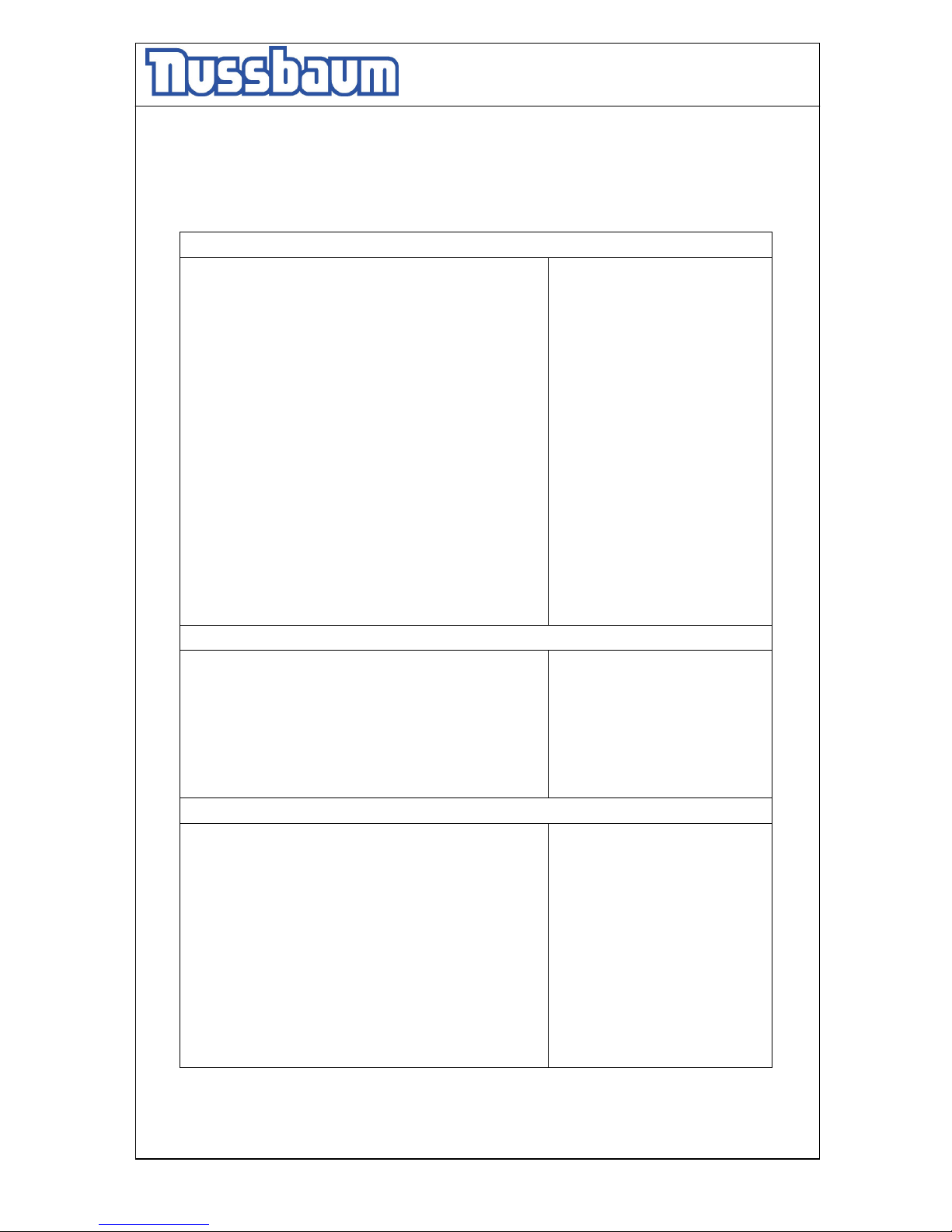
Problem: The Motors does not start!
Potential cau
ses:
- All columns are not working
- no power supply
- the main switch is not switched on.
- the fuse is defective
- the feed line is cut
- the thermo-fuse is active
- no column was selected
- the lift is out of the rule-window of ± 50 mm
Solution:
check the plug (see the arrow)
check the main fuse
check the position of the main
switch
check the fuse /exchange it
check the feed line
let it cool down approx.10 min.
check the press buttons
read chapter 6.1
Problem: The motor starts, the lift does n
ot lifting!
Potential causes:
- the vehicle is too heavy
- the level of the oil is too low
- the hydraulic valve is defective
Solution:
unload the vehicle
refill oil
call your service partner
Problem: The Mobile lift does not lowered!
Potential causes:
- the mobile lift is standing on a obstacle
- the hydraulic valve is defective
- the fuse is defective
- the button „lowering“ is not pressed or defective
- he holding valve is defective
- the safety star system is always locked
Solution:
single-mode operate
call your service partner
exchange the fuse
call your service partner
call your service partner
call your service partner
Page 24
Operating Instruction and Documentation
MCS 5500 ND WIRELESS
- 24 -
6.1 Lowering on a obstacle
The lift switched off if the lift is running onto an obstacle and out of the rule-window ± 50 mm.
6.1.1 Remove the obstacle
• Press the button “lifting ” in the single-mode. (see the chapter 5.4/5.5)
Keep an eye on it, at the singles-mode, that one MCS is lifted never too high,
otherwise the crash of the vehicle can occur.
6.2 Emergency lowering
A emergency lowering is an intervention into the control of the lift and can be done
only by experienced expert.
The emergency lowering must be carried in this order. Otherwise a malfunction can
lead it to damages or lead to danger for body and lives.
Every kind of external leakage has to be removed. This is necessary in particular
before an emergency lowering.
The emergency lowering may only be done by persons which are trained in using the
lift.
Reasons, that can make an emergency lowering necessary, are a defect of the electric system
or disturbances of the valves, etc.
In case of power-failure or defective Valves there is the possibility through suitable tools to
lower the lift in the lowest position, so that the vehicle can be driven off.
6.2.1 Procedure of the emergency lowering
• Switch off the main switch an d safe it. (lock it)
• Remove the covers of hydraulic unit.
• Secure the dangerous place around the lift.
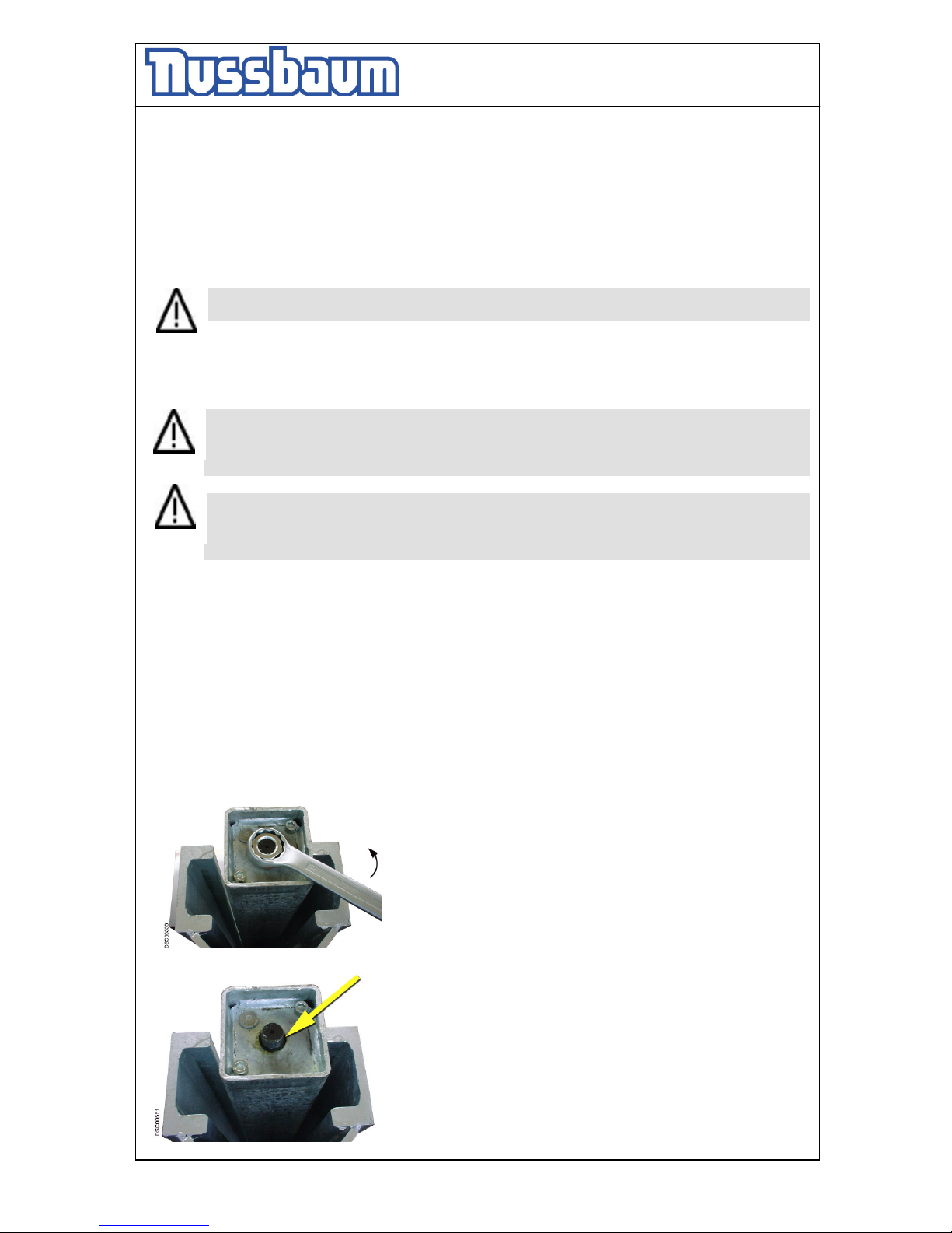
Pic 6:
Loosen and remove the 2 lock nuts with a suitable tool in arrow
direction. Carry out this process at both columns. (Key 41)
Pic 7:
The piston rod can be stuck through the dirty deposit at the
top of the hole. Use the solvent and lubricating stuff (for an
example WD40) to loosen the connection. The WD40 is
sprayed generously between the screw thread and the bore
hole (see arrow). The time of the effect follows the
contamination-degree.
Page 25
Operating Instruction and Documentation
MCS 5500 ND WIRELESS
- 25 -
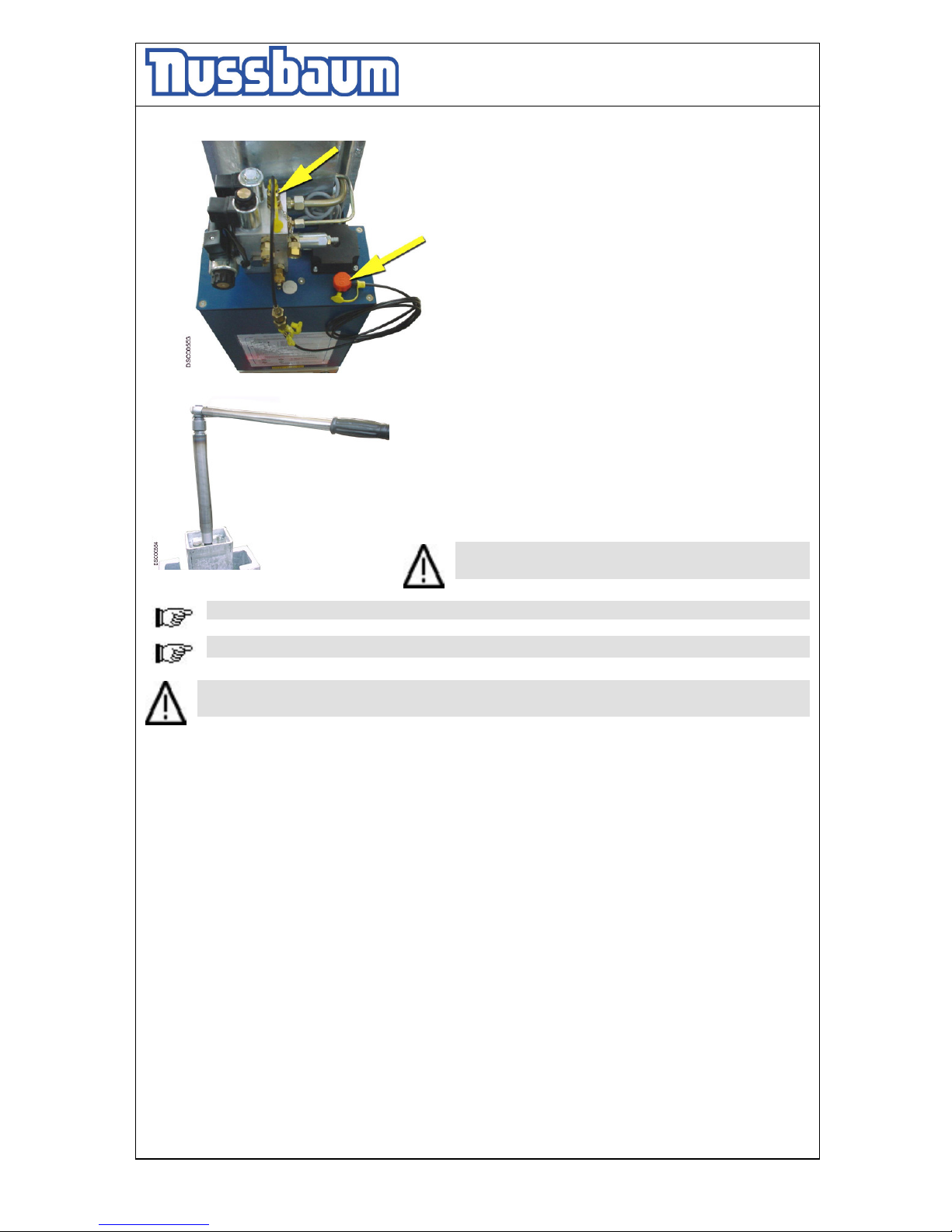
Pic 8:
Loosen the cap of the Minimess connection and the cap
of the tank. Fasten the Minimess hydraulic tube at the
screw fitting and put the other end into the tank.
Pic 9:
Use the long screw thread-bushing and turns with a suitable
tool (key-wideness 24, available with your dealer,), clockwise.
Lower the lifting carriage only approx. 5cm – 10 cm. Repeat
the process at the next column. Lower always 5 cm-10 cm
until all lift are in the lowest position.
Repair the defective lift. After it create a Reset which is
described in the operating instruction.
Attention!! Lower the automotive-lift only approx.
5cm – 10 cm.
Observe the complete emergency lowering process.
Do not work with the lift until the defective parts are changed.
You can only work again with the automotive-lift, if it is in a safety-related perfect
condition.
• After it, carry out an reset as described in the operating instruction.
Page 26
Operating Instruction and Documentation
MCS 5500 ND WIRELESS
- 26 -
6.3 Reset the MCS after an emergency lowering
A reset of the system can be enforced, if the MCS are in the lowest position.
An access on the DIP-Switch can take place only with a switched off main switch and
only through instructed, authorized technical personnel.
a) There must not be a vehicle on the lift.
b) Remove the cover of the operating unit.
c) Open the cover of the electrical box.
d) Press the button 1 (see pic. 14) and hold it.
e) Switch-off the main switch and wait 5 sec. Hold the reset button.
f) Switch-on the main switch and wait 5 sec. Hold the reset button.
g) Let go off the reset button.
h) Press the button „ lowering“ until all lifts are in the lowest position.
i) If necessary repeat several times the steps d) until h) so that the lift is surely in the lowest
position.
j) After that move the Dip-switch 7 on position „on“.
k) Dip-switch 5 stays on position „on“.
l) Repeat the steps d) until h)
m) After that, move the Dip-switch 7 on position „off“. Dip-switch 5 stays on position „on“.
n) On the computer-board must now three diodes lighten permanently. One additional diode must
be blinking in the frequency of approx. 1 sec.
o) Raise and lower the automotive lift a few times without load. Observe the process.
p) Mount the covers.
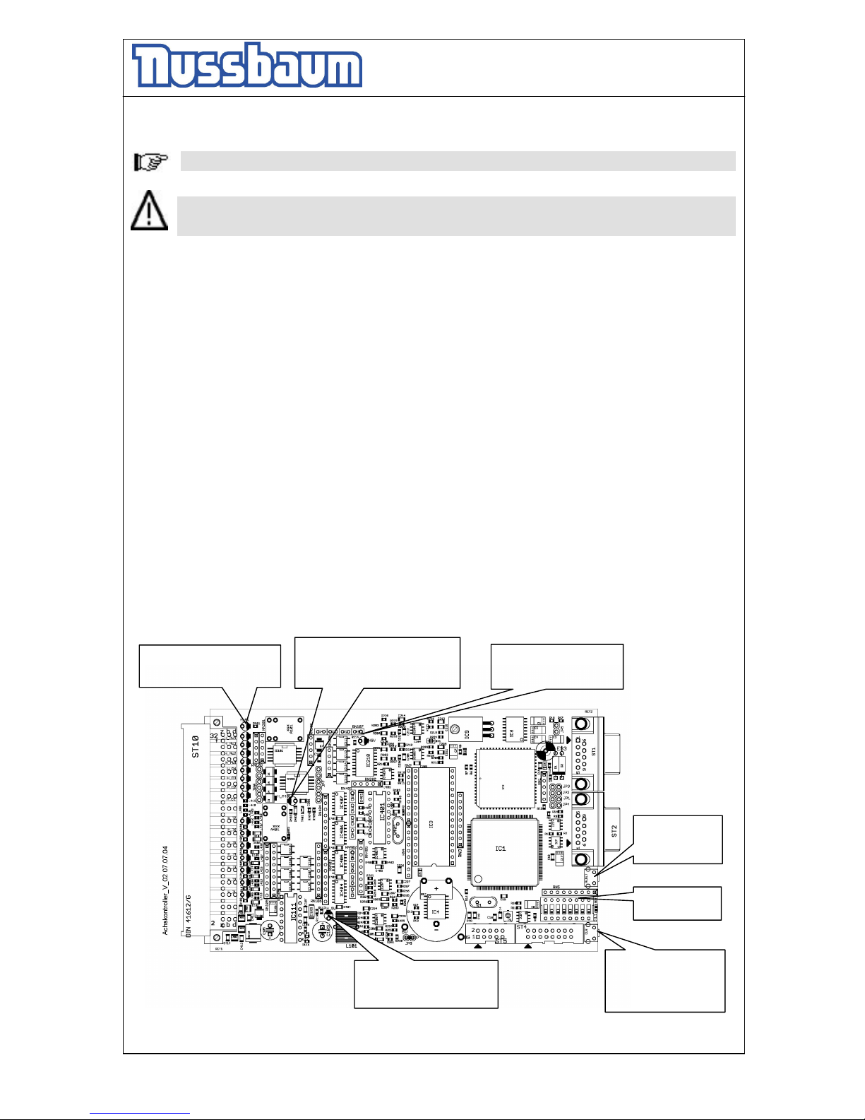
pic 18: controller
LED (A) switches off in case
of malfunction
LED (B) switches off in case of
malfunction in the measure
systems. (redundant: examine the
LED blinks to the rhythm of
1 sec under normal
operational function
Pos. 3
Reset
„controller
“
Pos. 1
Reset
„Monitoring controller
PIC“
Pos. 2
DIP-switches
LED switches off in case the
voltage of the processor is
under 5Volt
Page 27
Operating Instruction and Documentation
MCS 5500 ND WIRELESS
- 27 -
7.Inspection and Maintenance
Before conducting maintenance work, preparations must be made to ensure that
during maintenance and repair work there is no risk to the safety of people working
on or around the lift and also that there is no risk of damage to equipment being
used on or around the lift.
To guarantee the utmost availability and to ensure that the lift remains functional, maintenance
work contracts are organised between our clients and their local retailers.
A service must be performed at regular intervals of 3 months through the operator in
accordance with following service manual. If the lift is in continuous operation or in a dirty
environment, the maintenance rate must be increased.
During daily operation the lift must be closely observed to ensure that it is functioning correctly.
In the case of malfunction or leakage the technical service must be informed.
German legal guidelines : BSV (Prescription of working tools) + BGR500 (Work with
working tools)
7.1 Maintenance plan of the Mobile column lift
Before beginning any maintenance work isolate the power supply. Secure the main
switch (lock it). Secure the danger area around the automotive lift and secure the lift
against unintentional lowering
Maintenance plan
Period of time
Check the condition of the type plate, sticker, short operating instruction.
Clean it and if necessary replace it.
at least once a year
In case of heavy dirt deposit clean the piston rods of the hydraulic
cylinders from deposit. Remove the cover of the Mobile column lift. If
necessary raise the Mobile column lift with the single-mode in the
highest position.
Grease the piston rods with a high capacity lipid (approx. 5 g of S2
DIN51503 KE2G of the Renolit Company.
at least once a year
Clean and check the moving parts. Lubricate the moving parts of the lift
(hinge bolts, rolls, sliding surfaces) with a multipurpose lipid (example:
Auto Top 2000 LTD. Agip).
at least once a year
Page 28
Operating Instruction and Documentation
MCS 5500 ND WIRELESS
- 28 -
Check the colour if necessary make a repair.
Damages through outer effects are immediately to be treated after
recognising. In case of not-treatment of the positions, the powder-
coating can be durably damaged through infiltration of deposits of all
type
Grind these position (120 ryes) and after it degrease it. After it use a
suitable lacquer (Observe the RAL Number).
Check the zinc surface if necessary make a repair.
White rust becomes through lasting moisture, bad ventilation favours.
Rust is evoked by mechanical damages, wear, aggressive infiltration
(salt, water ; also in connection with other environmental influences) and
bad or not implemented cleaning.
Grind these position (A280 ryes) and after it degrease it. After it use a
suitable lacquer (Observe the RAL Number).
at least once a year
Check the hydraulic tubes for leackage. at least once a year
Check the oil level. Fill in a clean, high quality oil (32 cst)in the tank. at least once a year
The hydraulic oil has to be changed at least once a year. To change the
oil, lower the lift into the lowest position. Empty the tank and replaced
clean oil, approx. 17 litres are needed. A high quality hydraulic oil is
recommended, its should be 32 cst. (e.g.g. HLP 32 LTD. OEST
Company)
Use a ATF-Suffix hydraulic-oil (OEST Company ) if the ambient
temperature is under 5 degree centigrade. After the fill up, the hydraulic
oil must be between the upper and low marking of the oil level gauge.
at least once a year
Check all welded joints for cracks on the automotive-lift.
If any cracks are found on the lift cease use immediately. Switch-off and
secure the main switch (lock) and call the service partner.
at least once a year
Check the condition and the function of the moving device.(pressure
spring, bolts, roller
at least once a year
Check the safety device of the lift. (CE-STOP) at least once a year
Check the Battery of the controller (ASC). The Battery has a working life
at normal business between 4 ½ - 5 Years (manufacturers statement).
To avoid a permanent data-loss through an empty battery, you must
examine the battery of the controller during the regularly maintenance.
The measuring can only take place at the controller which was switched-
off. The measuring is possible with a commercial tensiometer.
standard voltage approx. 3.2 V (no exchange necessary), but a value
under 2.9 V, the
controller must be exchanged. Send the controller to the Nußbaum
Headquarter.
Before, contact your service partner.
at least once a year
Check the function of the handlever. at least once a year
Check condition and function of the moving device. at least once a year
Page 29
Operating Instruction and Documentation
MCS 5500 ND WIRELESS
- 29 -
Check the condition and function of the electrical buttons, main switch,
cables, plugs, CE-Stop.
at least once a year
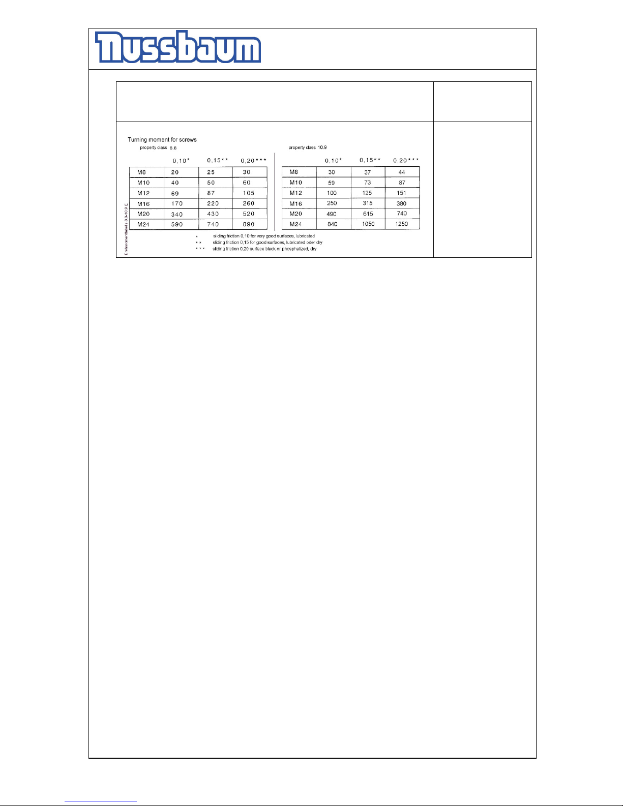
Check the turning moment of the screws (see the list)
at least once a year
7.2 Cleaning of the Mobile column lift
A regular and appropriate maintenance served the preservation of the lift.
It can be a prerequisite for claims at possible corrosion.
The best protection for the lift is the regular cleaning of dirt of all manner.
- Including this:
• de-icing salt
• sand, pebble stone, natural soil
• industrial dust of all manner
• water ; also in connection with other environmental influences
• aggressive deposit of all manner
• constant humidity by insufficient ventilation
How often must the lift be cleaned ?
This is dependent on the use, of the working with the lift, of the cleanness of the workshop and
location of the lift. The degree of the dirt is dependent on the season, of the weather conditions
and the ventilation of the workshop.
Under bad circumstances it is necessary to clean the lift every week, but a cleaning every
month can suffice.
Clean the lift and the floor with a non-aggressive and non-abrasive detergent. Use gentle
detergent to clean the parts. Use an standard washing-up liquid and lukewarm water.
- Do not use for cleaning a steam jet cleaning
- Remove all dirt careful with a sponge if necessary with a brush.
- Pay attention that are no remains of the washing-up liquids on the lift after cleaning.
- Do not use aggressive means for cleaning the workshop floor and the automotive lift.
- A permanent contact with every kind of liquid is forbidden. Do not use any high
pressure device for cleaning the lift.
Page 30
Operating Instruction and Documentation
MCS 5500 ND WIRELESS
- 30 -
8.Security check
The security check is necessary to guarantee the safety of the lifting during use. It has to be
performed in the following cases:
1. Before the initial operation, after the first installation
Use the form “First security check before initiation”
2. In regular intervals after the initial operation, at least annually.
Use the form “Regular security check at least annually”
3. Every time the construction of that particular lift has been changed.
Use the form “Extraordinary security check”
The first and the regular security check must be performed by a competent person. It is
recommended to service the lift at this occasion.
After the construction of the lift has been changed (changing the lifting height or
capacity for example) and after serious maintenance works (welding on carrying parts)
an extraordinary security check must be performed by an expert.
This manual contains form with a schedule for the security checks. Please us the adequate form
for the security checks. The form should remain in this manual after they have been filled out. In
the following there is a short description about special safety devices.
Page 31

Operating Instruction and Documentation
MCS 5500 ND WIRELESS
- 31 -
9.Handing over and Initiation
9.1 Regulations
• It’s not allowed to install the standard-automotive lift in a hazardous location or washing
bays.
• Every solid surface (concrete quality min C20/25) is suitable as installation-place.
We point out the minimum requirement of the foundation in our plans. The condition of the
local realities (for example: ground under the foundation) does not lie our responsibility. If
necessary an architect must be consulted.
• Standard Version: an electrical supply 3PH,N+PE,400V,50Hz has to be provided.
In the case of supply into other countries the lifting platform is accordingly electrically
prepared.
9.2 Initiation
Before the initiation a security check must be performed. Therefore use form: First
security check.
If the lift is installed by a competent person, he will perform this security check. If the
operator installs the lift by himself, he has to instruct a competent person to perform the
security check.
The competent confirms the faultless function of the lift in the installation record and form for
the security check and allows the lift to be used.
Please send the filled installation record to the manufacturer after installation.
Page 32
Operating Instruction and Documentation
MCS 5500 ND WIRELESS
- 32 -
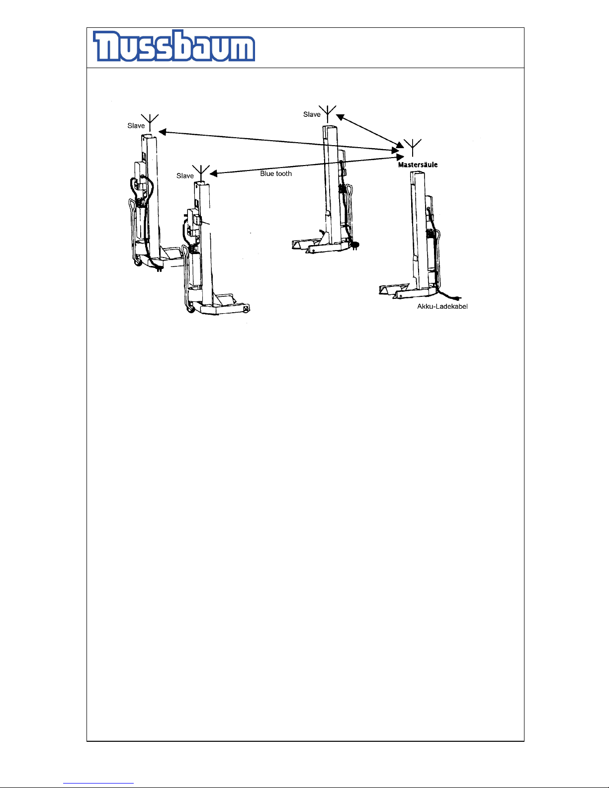
9.3 Position of the columns
Master
column
Cable for charging the Battery
Page 33
Operating Instruction and Documentation
MCS 5500 ND WIRELESS
- 33 -
First security check before installation
Filling out and leave in this manual Serial-number:_________________________
all defect veri-
kind of check right missing fication remark
----------------------------------------------------------------------------------------------------------------------------------------
Type plate........................................................... ..................................................
Short operating instruction................................. ..................................................
Warning designation.......................................... ..................................................
Function „Sychronous-mode“............................ ..................................................
Function „single-mode“...................................... ..................................................
Function „axle-mode“........................................ ..................................................
Function button „lifting,lowering“..................... ..................................................
Function button „lifting,lowering“..................... ..................................................
Function hand lever........................................... ..................................................
Function safety star system............................... ..................................................
Condition MCS................................................. ..................................................
Condition colour................................................. ..................................................
Condition pulleys............................................... ..................................................
Condition bearings............................................. ..................................................
Condition weldings........................................... ..................................................
Construction (deformation,cracking)................. ..................................................
Condition/Function photoelectric....................... ..................................................
Condition cable + protecting tube + plug ......... ..................................................
Condition hydraul.ic unit................................... ..................................................
Condition surface piston rod ........................ ..................................................
Condition of the cover .................................... ..................................................
Tightness of the hydraulic system..................... ..................................................
Level of hydraulic oil ................................... ..................................................
Condition hydarulic tubes .............................. ..................................................
Condition electrical wires................................... ..................................................
Test MCS with a vehicle................................... ..................................................
Mobility of the MCS......................................... ..................................................
Function CE-Stop............................................. ..................................................
( mark here applicable, in case of verification mark in addition to the first mark!)
----------------------------------------------------------------------------------------------------------------------------------------
Security check carried out:............................…........................................................................................
Carried out the company:........................................…………....................................................................
Name, address of the competent:....................................................…......................................................
Result of the Check:
Initiation not permitted, verification necessary
Initiation possible, repair failures
until.........................................................
No failings, Initiation possible
........................................................ ...........................................................
signature of the expert signature of the operator
If failures must be repaired:
Failures repaired at: .......................... ...................................................
signature of the operator
(Use another form for verification!)
Page 34
Operating Instruction and Documentation
MCS 5500 ND WIRELESS
- 34 -
Regular security check and Maintenance
Filling out and leave in this manual Serial-number:_________________________
all defect veri-
kind of check right missing fication remark
----------------------------------------------------------------------------------------------------------------------------------------
Short operating instruction................................. ..................................................
Warning designation.......................................... ..................................................
Function „Sychronous-mode“............................ ..................................................
Function „single-mode“...................................... ..................................................
Function „axle-mode“........................................ ..................................................
Function button „lifting,lowering“..................... ..................................................
Function button „lifting,lowering“..................... ..................................................
Function hand lever........................................... ..................................................
Function safety star system............................... ..................................................
Condition MCS................................................. ..................................................
Condition colour................................................. ..................................................
Condition pulleys............................................... ..................................................
Condition bearings............................................. ..................................................
Condition weldings........................................... ..................................................
Construction (deformation,cracking)................. ..................................................
Condition/Function photoelectric....................... ..................................................
Condition cable + protecting tube + plug ......... ..................................................
Condition hydraul.ic unit................................... ..................................................
Condition surface piston rod ........................ ..................................................
Condition of the cover .................................... ..................................................
Tightness of the hydraulic system..................... ..................................................
Level of hydraulic oil ................................... ..................................................
Condition hydarulic tubes .............................. ..................................................
Condition electrical wires................................... ..................................................
Test MCS with a vehicle................................... ..................................................
Mobility of the MCS......................................... ..................................................
Function CE-Stop............................................. ..................................................
( mark here applicable, in case of verification mark in addition to the first mark!)
----------------------------------------------------------------------------------------------------------------------------------------
Security check carried out:............................…........................................................................................
Carried out the company:........................................…………....................................................................
Name, address of the competent:....................................................…......................................................
Result of the Check:
Initiation not permitted, verification necessary
Initiation possible, repair failures
until.........................................................
No failings, Initiation possible
........................................................ ...........................................................
signature of the expert signature of the operator
If failures must be repaired:
Failures repaired at: .......................... ...................................................
signature of the operator
(Use another form for verification!)
Page 35

Operating Instruction and Documentation
MCS 5500 ND WIRELESS
- 35 -
Regular security check and Maintenance
Filling out and leave in this manual Serial-number:_________________________
all defect veri-
kind of check right missing fication remark
----------------------------------------------------------------------------------------------------------------------------------------
Short operating instruction................................. ..................................................
Warning designation.......................................... ..................................................
Function „Sychronous-mode“............................ ..................................................
Function „single-mode“...................................... ..................................................
Function „axle-mode“........................................ ..................................................
Function button „lifting,lowering“..................... ..................................................
Function button „lifting,lowering“..................... ..................................................
Function hand lever........................................... ..................................................
Function safety star system............................... ..................................................
Condition MCS................................................. ..................................................
Condition colour................................................. ..................................................
Condition pulleys............................................... ..................................................
Condition bearings............................................. ..................................................
Condition weldings........................................... ..................................................
Construction (deformation,cracking)................. ..................................................
Condition/Function photoelectric....................... ..................................................
Condition cable + protecting tube + plug ......... ..................................................
Condition hydraul.ic unit................................... ..................................................
Condition surface piston rod ........................ ..................................................
Condition of the cover .................................... ..................................................
Tightness of the hydraulic system..................... ..................................................
Level of hydraulic oil ................................... ..................................................
Condition hydarulic tubes .............................. ..................................................
Condition electrical wires................................... ..................................................
Test MCS with a vehicle................................... ..................................................
Mobility of the MCS......................................... ..................................................
Function CE-Stop............................................. ..................................................
( mark here applicable, in case of verification mark in addition to the first mark!)
----------------------------------------------------------------------------------------------------------------------------------------
Security check carried out:............................…........................................................................................
Carried out the company:........................................…………....................................................................
Name, address of the competent:....................................................…......................................................
Result of the Check:
Initiation not permitted, verification necessary
Initiation possible, repair failures
until.........................................................
No failings, Initiation possible
........................................................ ...........................................................
signature of the expert signature of the operator
If failures must be repaired:
Failures repaired at: .......................... ...................................................
signature of the operator
(Use another form for verification!)
Page 36
Operating Instruction and Documentation
MCS 5500 ND WIRELESS
- 36 -
Regular security check and Maintenance
Filling out and leave in this manual Serial-number:_________________________
all defect veri-
kind of check right missing fication remark
----------------------------------------------------------------------------------------------------------------------------------------
Short operating instruction................................. ..................................................
Warning designation.......................................... ..................................................
Function „Sychronous-mode“............................ ..................................................
Function „single-mode“...................................... ..................................................
Function „axle-mode“........................................ ..................................................
Function button „lifting,lowering“..................... ..................................................
Function button „lifting,lowering“..................... ..................................................
Function hand lever........................................... ..................................................
Function safety star system............................... ..................................................
Condition MCS................................................. ..................................................
Condition colour................................................. ..................................................
Condition pulleys............................................... ..................................................
Condition bearings............................................. ..................................................
Condition weldings........................................... ..................................................
Construction (deformation,cracking)................. ..................................................
Condition/Function photoelectric....................... ..................................................
Condition cable + protecting tube + plug ......... ..................................................
Condition hydraul.ic unit................................... ..................................................
Condition surface piston rod ........................ ..................................................
Condition of the cover .................................... ..................................................
Tightness of the hydraulic system..................... ..................................................
Level of hydraulic oil ................................... ..................................................
Condition hydarulic tubes .............................. ..................................................
Condition electrical wires................................... ..................................................
Test MCS with a vehicle................................... ..................................................
Mobility of the MCS......................................... ..................................................
Function CE-Stop............................................. ..................................................
( mark here applicable, in case of verification mark in addition to the first mark!)
----------------------------------------------------------------------------------------------------------------------------------------
Security check carried out:............................…........................................................................................
Carried out the company:........................................…………....................................................................
Name, address of the competent:....................................................…......................................................
Result of the Check:
Initiation not permitted, verification necessary
Initiation possible, repair failures
until.........................................................
No failings, Initiation possible
........................................................ ...........................................................
signature of the expert signature of the operator
If failures must be repaired:
Failures repaired at: .......................... ...................................................
signature of the operator
(Use another form for verification!)
Page 37
Operating Instruction and Documentation
MCS 5500 ND WIRELESS
- 37 -
Regular security check and Maintenance
Filling out and leave in this manual Serial-number:_________________________
all defect veri-
kind of check right missing fication remark
----------------------------------------------------------------------------------------------------------------------------------------
Short operating instruction................................. ..................................................
Warning designation.......................................... ..................................................
Function „Sychronous-mode“............................ ..................................................
Function „single-mode“...................................... ..................................................
Function „axle-mode“........................................ ..................................................
Function button „lifting,lowering“..................... ..................................................
Function button „lifting,lowering“..................... ..................................................
Function hand lever........................................... ..................................................
Function safety star system............................... ..................................................
Condition MCS................................................. ..................................................
Condition colour................................................. ..................................................
Condition pulleys............................................... ..................................................
Condition bearings............................................. ..................................................
Condition weldings........................................... ..................................................
Construction (deformation,cracking)................. ..................................................
Condition/Function photoelectric....................... ..................................................
Condition cable + protecting tube + plug ......... ..................................................
Condition hydraul.ic unit................................... ..................................................
Condition surface piston rod ........................ ..................................................
Condition of the cover .................................... ..................................................
Tightness of the hydraulic system..................... ..................................................
Level of hydraulic oil ................................... ..................................................
Condition hydarulic tubes .............................. ..................................................
Condition electrical wires................................... ..................................................
Test MCS with a vehicle................................... ..................................................
Mobility of the MCS......................................... ..................................................
Function CE-Stop............................................. ..................................................
( mark here applicable, in case of verification mark in addition to the first mark!)
----------------------------------------------------------------------------------------------------------------------------------------
Security check carried out:............................…........................................................................................
Carried out the company:........................................…………....................................................................
Name, address of the competent:....................................................…......................................................
Result of the Check:
Initiation not permitted, verification necessary
Initiation possible, repair failures
until.........................................................
No failings, Initiation possible
........................................................ ...........................................................
signature of the expert signature of the operator
If failures must be repaired:
Failures repaired at: .......................... ...................................................
signature of the operator
(Use another form for verification!)
Page 38
Operating Instruction and Documentation
MCS 5500 ND WIRELESS
- 38 -
Regular security check and Maintenance
Filling out and leave in this manual Serial-number:_________________________
all defect veri-
kind of check right missing fication remark
----------------------------------------------------------------------------------------------------------------------------------------
Short operating instruction................................. ..................................................
Warning designation.......................................... ..................................................
Function „Sychronous-mode“............................ ..................................................
Function „single-mode“...................................... ..................................................
Function „axle-mode“........................................ ..................................................
Function button „lifting,lowering“..................... ..................................................
Function button „lifting,lowering“..................... ..................................................
Function hand lever........................................... ..................................................
Function safety star system............................... ..................................................
Condition MCS................................................. ..................................................
Condition colour................................................. ..................................................
Condition pulleys............................................... ..................................................
Condition bearings............................................. ..................................................
Condition weldings........................................... ..................................................
Construction (deformation,cracking)................. ..................................................
Condition/Function photoelectric....................... ..................................................
Condition cable + protecting tube + plug ......... ..................................................
Condition hydraul.ic unit................................... ..................................................
Condition surface piston rod ........................ ..................................................
Condition of the cover .................................... ..................................................
Tightness of the hydraulic system..................... ..................................................
Level of hydraulic oil ................................... ..................................................
Condition hydarulic tubes .............................. ..................................................
Condition electrical wires................................... ..................................................
Test MCS with a vehicle................................... ..................................................
Mobility of the MCS......................................... ..................................................
Function CE-Stop............................................. ..................................................
( mark here applicable, in case of verification mark in addition to the first mark!)
----------------------------------------------------------------------------------------------------------------------------------------
Security check carried out:............................…........................................................................................
Carried out the company:........................................…………....................................................................
Name, address of the competent:....................................................…......................................................
Result of the Check:
Initiation not permitted, verification necessary
Initiation possible, repair failures
until.........................................................
No failings, Initiation possible
........................................................ ...........................................................
signature of the expert signature of the operator
If failures must be repaired:
Failures repaired at: .......................... ...................................................
signature of the operator
(Use another form for verification!)
Page 39
Operating Instruction and Documentation
MCS 5500 ND WIRELESS
- 39 -
Regular security check and Maintenance
Filling out and leave in this manual Serial-number:_________________________
all defect veri-
kind of check right missing fication remark
----------------------------------------------------------------------------------------------------------------------------------------
Short operating instruction................................. ..................................................
Warning designation.......................................... ..................................................
Function „Sychronous-mode“............................ ..................................................
Function „single-mode“...................................... ..................................................
Function „axle-mode“........................................ ..................................................
Function button „lifting,lowering“..................... ..................................................
Function button „lifting,lowering“..................... ..................................................
Function hand lever........................................... ..................................................
Function safety star system............................... ..................................................
Condition MCS................................................. ..................................................
Condition colour................................................. ..................................................
Condition pulleys............................................... ..................................................
Condition bearings............................................. ..................................................
Condition weldings........................................... ..................................................
Construction (deformation,cracking)................. ..................................................
Condition/Function photoelectric....................... ..................................................
Condition cable + protecting tube + plug ......... ..................................................
Condition hydraul.ic unit................................... ..................................................
Condition surface piston rod ........................ ..................................................
Condition of the cover .................................... ..................................................
Tightness of the hydraulic system..................... ..................................................
Level of hydraulic oil ................................... ..................................................
Condition hydarulic tubes .............................. ..................................................
Condition electrical wires................................... ..................................................
Test MCS with a vehicle................................... ..................................................
Mobility of the MCS......................................... ..................................................
Function CE-Stop............................................. ..................................................
( mark here applicable, in case of verification mark in addition to the first mark!)
----------------------------------------------------------------------------------------------------------------------------------------
Security check carried out:............................…........................................................................................
Carried out the company:........................................…………....................................................................
Name, address of the competent:....................................................…......................................................
Result of the Check:
Initiation not permitted, verification necessary
Initiation possible, repair failures
until.........................................................
No failings, Initiation possible
........................................................ ...........................................................
signature of the expert signature of the operator
If failures must be repaired:
Failures repaired at: .......................... ...................................................
signature of the operator
(Use another form for verification!)
Page 40
Operating Instruction and Documentation
MCS 5500 ND WIRELESS
- 40 -
Regular security check and Maintenance
Filling out and leave in this manual Serial-number:_________________________
all defect veri-
kind of check right missing fication remark
----------------------------------------------------------------------------------------------------------------------------------------
Short operating instruction................................. ..................................................
Warning designation.......................................... ..................................................
Function „Sychronous-mode“............................ ..................................................
Function „single-mode“...................................... ..................................................
Function „axle-mode“........................................ ..................................................
Function button „lifting,lowering“..................... ..................................................
Function button „lifting,lowering“..................... ..................................................
Function hand lever........................................... ..................................................
Function safety star system............................... ..................................................
Condition MCS................................................. ..................................................
Condition colour................................................. ..................................................
Condition pulleys............................................... ..................................................
Condition bearings............................................. ..................................................
Condition weldings........................................... ..................................................
Construction (deformation,cracking)................. ..................................................
Condition/Function photoelectric....................... ..................................................
Condition cable + protecting tube + plug ......... ..................................................
Condition hydraul.ic unit................................... ..................................................
Condition surface piston rod ........................ ..................................................
Condition of the cover .................................... ..................................................
Tightness of the hydraulic system..................... ..................................................
Level of hydraulic oil ................................... ..................................................
Condition hydarulic tubes .............................. ..................................................
Condition electrical wires................................... ..................................................
Test MCS with a vehicle................................... ..................................................
Mobility of the MCS......................................... ..................................................
Function CE-Stop............................................. ..................................................
( mark here applicable, in case of verification mark in addition to the first mark!)
----------------------------------------------------------------------------------------------------------------------------------------
Security check carried out:............................…........................................................................................
Carried out the company:........................................…………....................................................................
Name, address of the competent:....................................................…......................................................
Result of the Check:
Initiation not permitted, verification necessary
Initiation possible, repair failures
until.........................................................
No failings, Initiation possible
........................................................ ...........................................................
signature of the expert signature of the operator
If failures must be repaired:
Failures repaired at: .......................... ...................................................
signature of the operator
(Use another form for verification!)
Page 41
Operating Instruction and Documentation
MCS 5500 ND WIRELESS
- 41 -
Regular security check and Maintenance
Filling out and leave in this manual Serial-number:_________________________
all defect veri-
kind of check right missing fication remark
----------------------------------------------------------------------------------------------------------------------------------------
Short operating instruction................................. ..................................................
Warning designation.......................................... ..................................................
Function „Sychronous-mode“............................ ..................................................
Function „single-mode“...................................... ..................................................
Function „axle-mode“........................................ ..................................................
Function button „lifting,lowering“..................... ..................................................
Function button „lifting,lowering“..................... ..................................................
Function hand lever........................................... ..................................................
Function safety star system............................... ..................................................
Condition MCS................................................. ..................................................
Condition colour................................................. ..................................................
Condition pulleys............................................... ..................................................
Condition bearings............................................. ..................................................
Condition weldings........................................... ..................................................
Construction (deformation,cracking)................. ..................................................
Condition/Function photoelectric....................... ..................................................
Condition cable + protecting tube + plug ......... ..................................................
Condition hydraul.ic unit................................... ..................................................
Condition surface piston rod ........................ ..................................................
Condition of the cover .................................... ..................................................
Tightness of the hydraulic system..................... ..................................................
Level of hydraulic oil ................................... ..................................................
Condition hydarulic tubes .............................. ..................................................
Condition electrical wires................................... ..................................................
Test MCS with a vehicle................................... ..................................................
Mobility of the MCS......................................... ..................................................
Function CE-Stop............................................. ..................................................
( mark here applicable, in case of verification mark in addition to the first mark!)
----------------------------------------------------------------------------------------------------------------------------------------
Security check carried out:............................…........................................................................................
Carried out the company:........................................…………....................................................................
Name, address of the competent:....................................................…......................................................
Result of the Check:
Initiation not permitted, verification necessary
Initiation possible, repair failures
until.........................................................
No failings, Initiation possible
........................................................ ...........................................................
signature of the expert signature of the operator
If failures must be repaired:
Failures repaired at: .......................... ...................................................
signature of the operator
(Use another form for verification!)
Page 42
Operating Instruction and Documentation
MCS 5500 ND WIRELESS
- 42 -
Extraordinary security check
Filling out and leave in this manual Serial-number:_________________________
all defect veri-
kind of check right missing fication remark
----------------------------------------------------------------------------------------------------------------------------------------
Short operating instruction................................. ..................................................
Warning designation.......................................... ..................................................
Function „Sychronous-mode“............................ ..................................................
Function „single-mode“...................................... ..................................................
Function „axle-mode“........................................ ..................................................
Function button „lifting,lowering“..................... ..................................................
Function button „lifting,lowering“..................... ..................................................
Function hand lever........................................... ..................................................
Function safety star system............................... ..................................................
Condition MCS................................................. ..................................................
Condition colour................................................. ..................................................
Condition pulleys............................................... ..................................................
Condition bearings............................................. ..................................................
Condition weldings........................................... ..................................................
Construction (deformation,cracking)................. ..................................................
Condition/Function photoelectric....................... ..................................................
Condition cable + protecting tube + plug ......... ..................................................
Condition hydraul.ic unit................................... ..................................................
Condition surface piston rod ........................ ..................................................
Condition of the cover .................................... ..................................................
Tightness of the hydraulic system..................... ..................................................
Level of hydraulic oil ................................... ..................................................
Condition hydarulic tubes .............................. ..................................................
Condition electrical wires................................... ..................................................
Test MCS with a vehicle................................... ..................................................
Mobility of the MCS......................................... ..................................................
Function CE-Stop............................................. ..................................................
( mark here applicable, in case of verification mark in addition to the first mark!)
----------------------------------------------------------------------------------------------------------------------------------------
Security check carried out:............................…........................................................................................
Carried out the company:........................................…………....................................................................
Name, address of the competent:....................................................…......................................................
Result of the Check:
Initiation not permitted, verification necessary
Initiation possible, repair failures
until.........................................................
No failings, Initiation possible
........................................................ ...........................................................
signature of the expert signature of the operator
If failures must be repaired:
Failures repaired at: .......................... ...................................................
signature of the operator
(Use another form for verification!)
Page 43
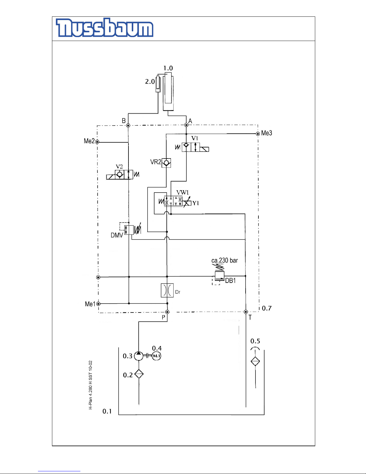
Operating Instruction and Documentation
MCS 5500 ND WIRELESS
- 43 -
Hydraulic diagram drawing
Page 44

Operating Instruction and Documentation
MCS 5500 ND WIRELESS
- 44 -
Hydraulic parts list
Pos. Description order number
0.1 oil tank
0.2 filter 980012
0.3 gear pump 982268
0.4 sub oil motor 992100
0.5 oil level gauge 980011
0.7 hydraulic block complete 163118
- hydraulic throttles D1,5mm
DB1 pressure relief valve 600150
DMV pressure relief valve 162406
M1-M3 measure connection 118495
VW1 proportional valve 161060
V1 2/2 way valve 158502
V2 2/2 way valve 158503
VR2 holding valve 130053
1.0 cylinder 155RGK52000
2.0 unlocking cylinder
Page 45
Operating Instruction and Documentation
MCS 5500 ND WIRELESS
- 45 -
Electrical diagram drawing
Page 46
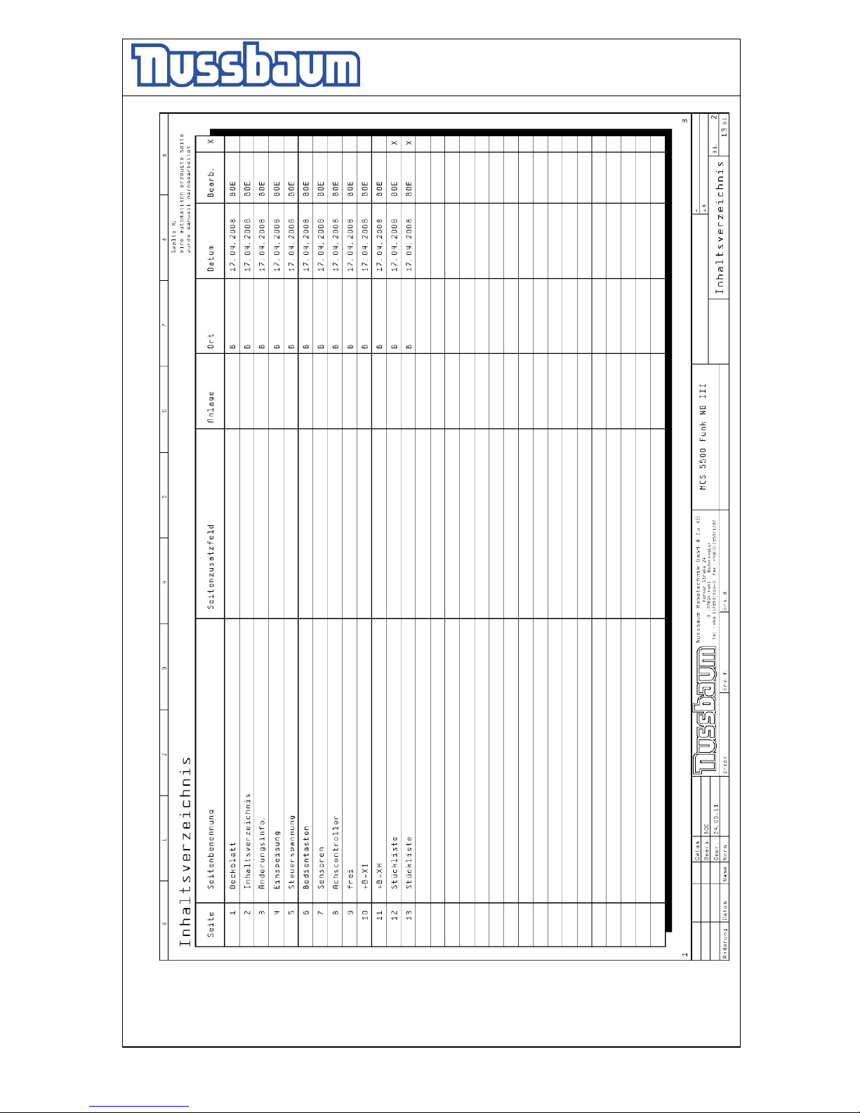
Operating Instruction and Documentation
MCS 5500 ND WIRELESS
- 46 -
Page 47
Operating Instruction and Documentation
MCS 5500 ND WIRELESS
- 47 -
Page 48
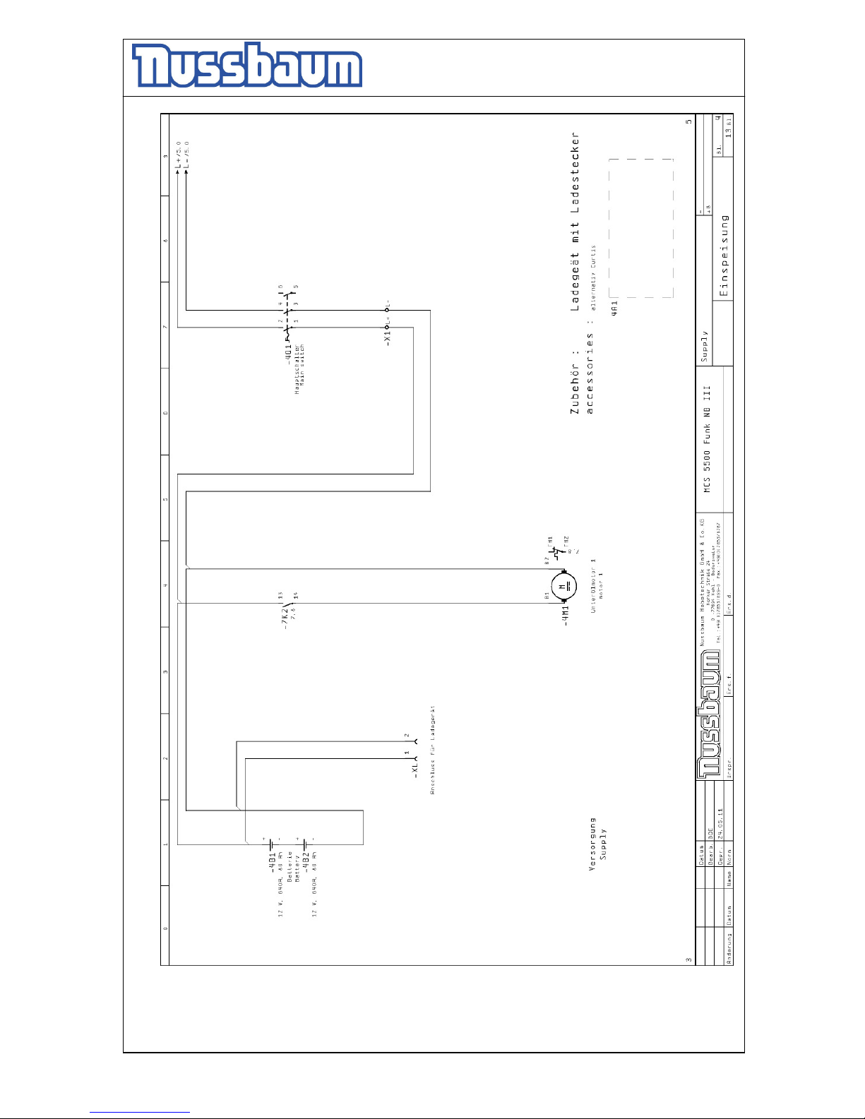
Operating Instruction and Documentation
MCS 5500 ND WIRELESS
- 48 -
Page 49
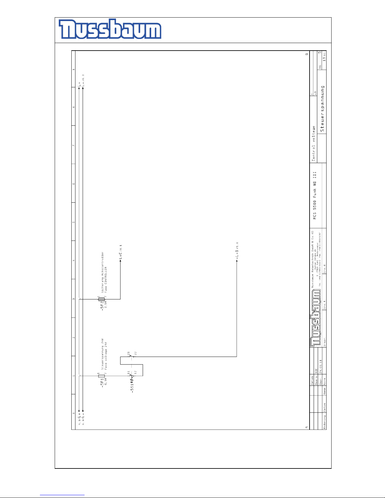
Operating Instruction and Documentation
MCS 5500 ND WIRELESS
- 49 -
Page 50
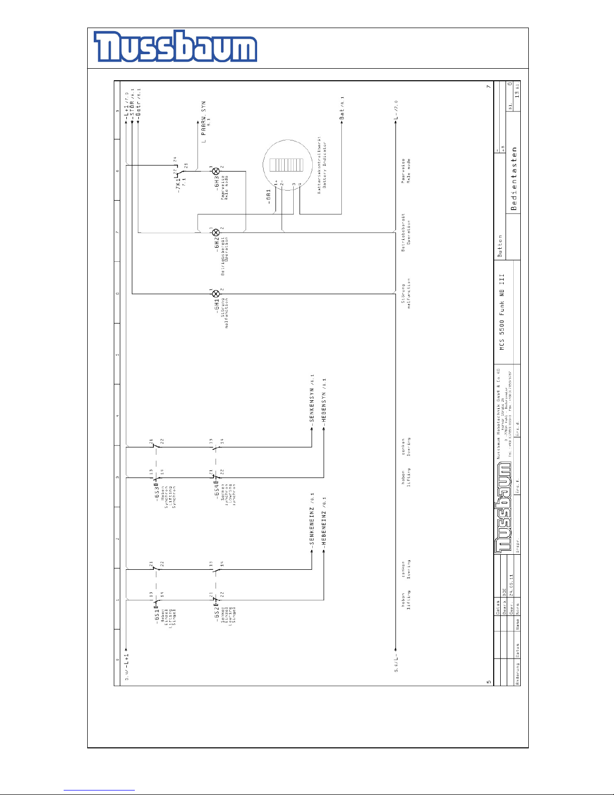
Operating Instruction and Documentation
MCS 5500 ND WIRELESS
- 50 -
Page 51
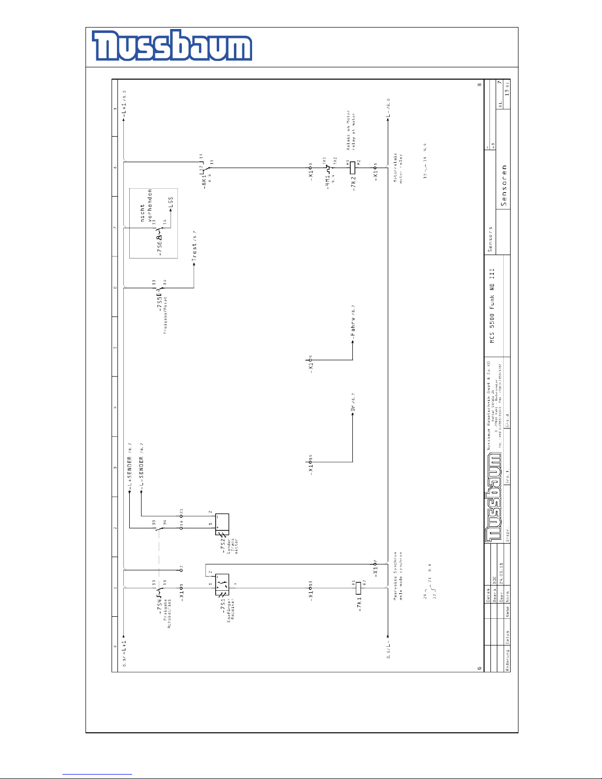
Operating Instruction and Documentation
MCS 5500 ND WIRELESS
- 51 -
Page 52
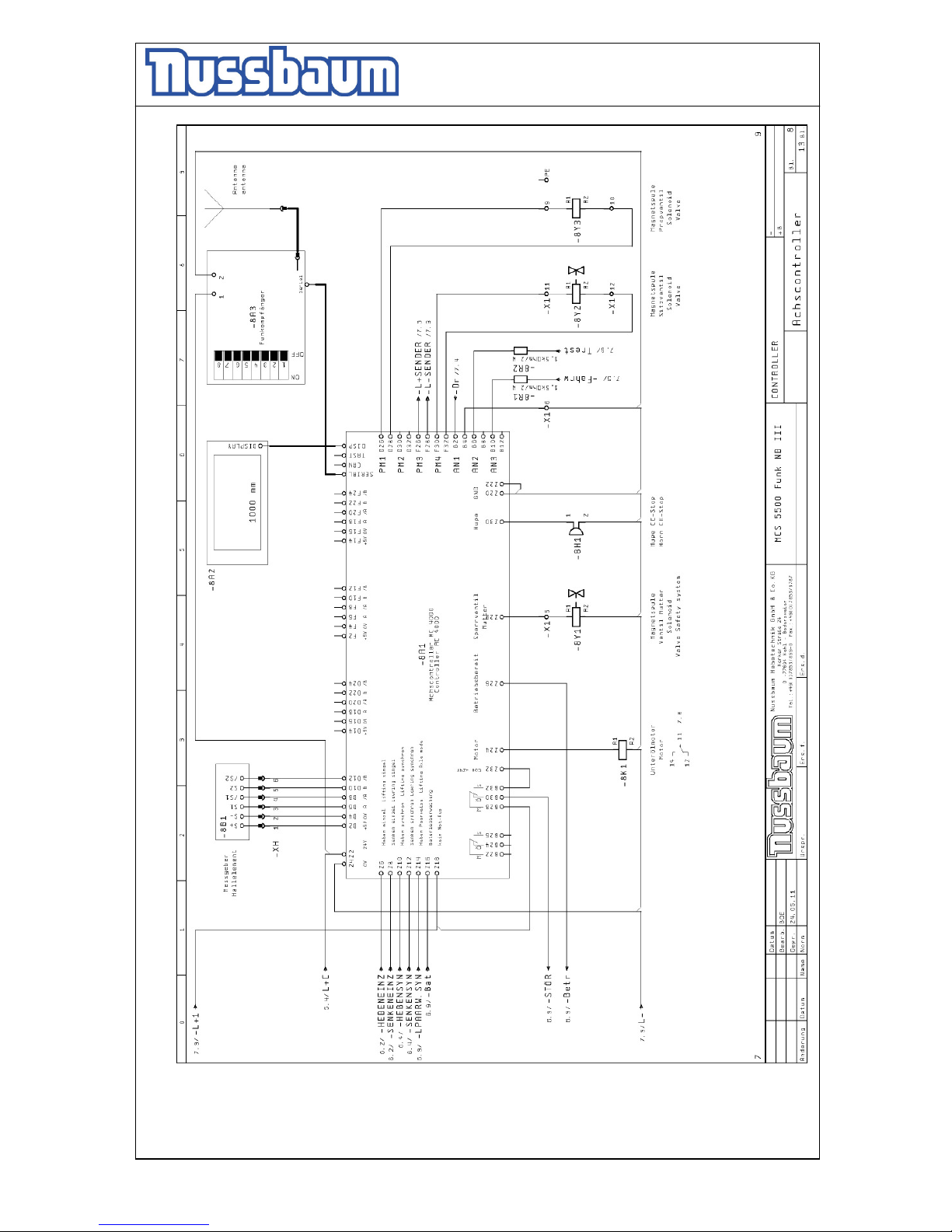
Operating Instruction and Documentation
MCS 5500 ND WIRELESS
- 52 -
Page 53
Operating Instruction and Documentation
MCS 5500 ND WIRELESS
- 53 -
Page 54
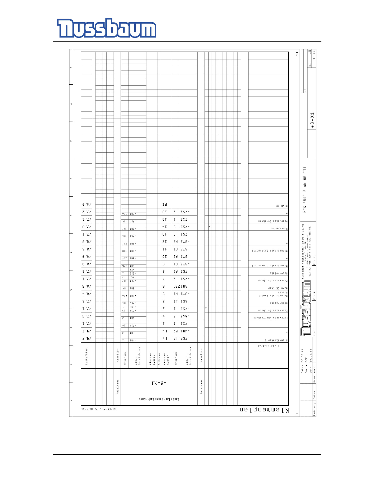
Operating Instruction and Documentation
MCS 5500 ND WIRELESS
- 54 -
Page 55
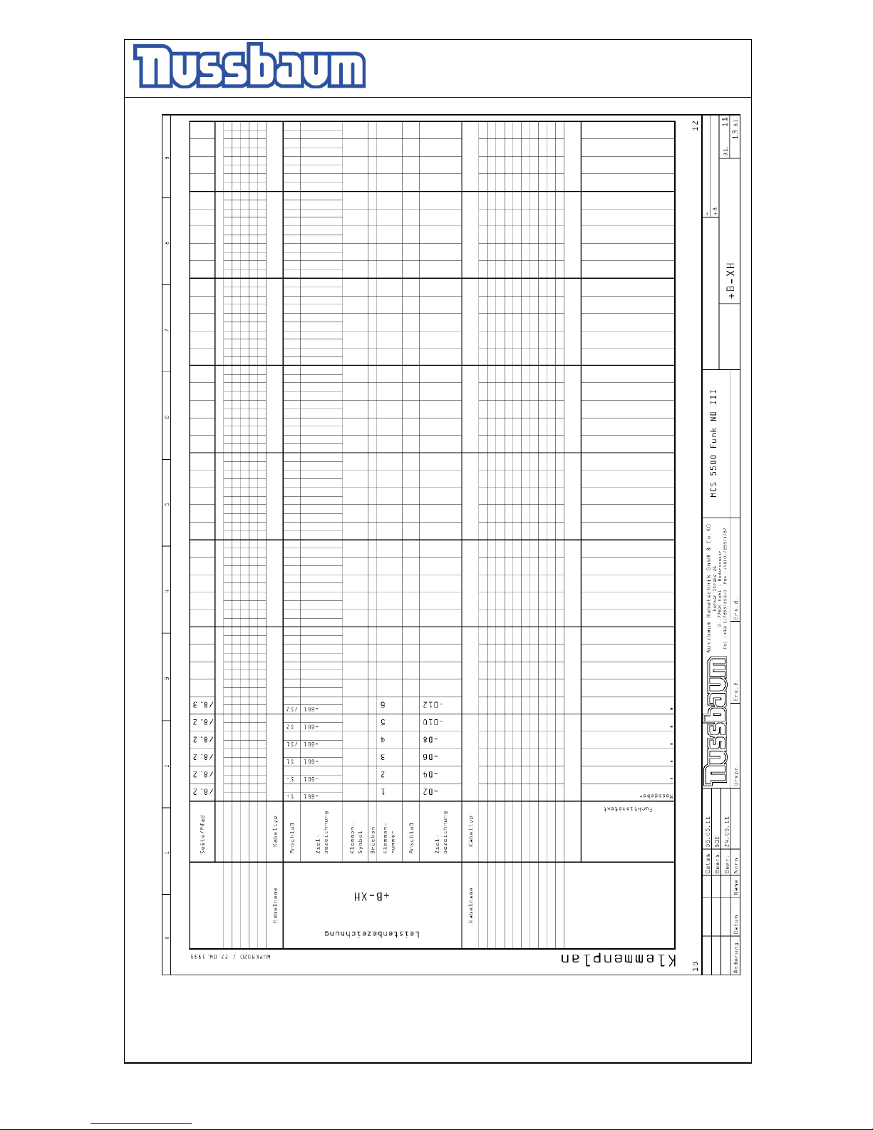
Operating Instruction and Documentation
MCS 5500 ND WIRELESS
- 55 -
Page 56
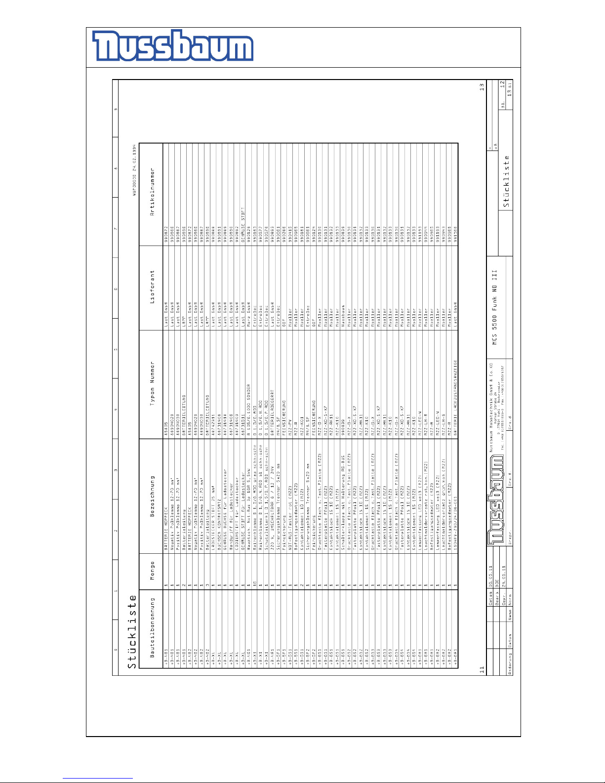
Operating Instruction and Documentation
MCS 5500 ND WIRELESS
- 56 -
Page 57
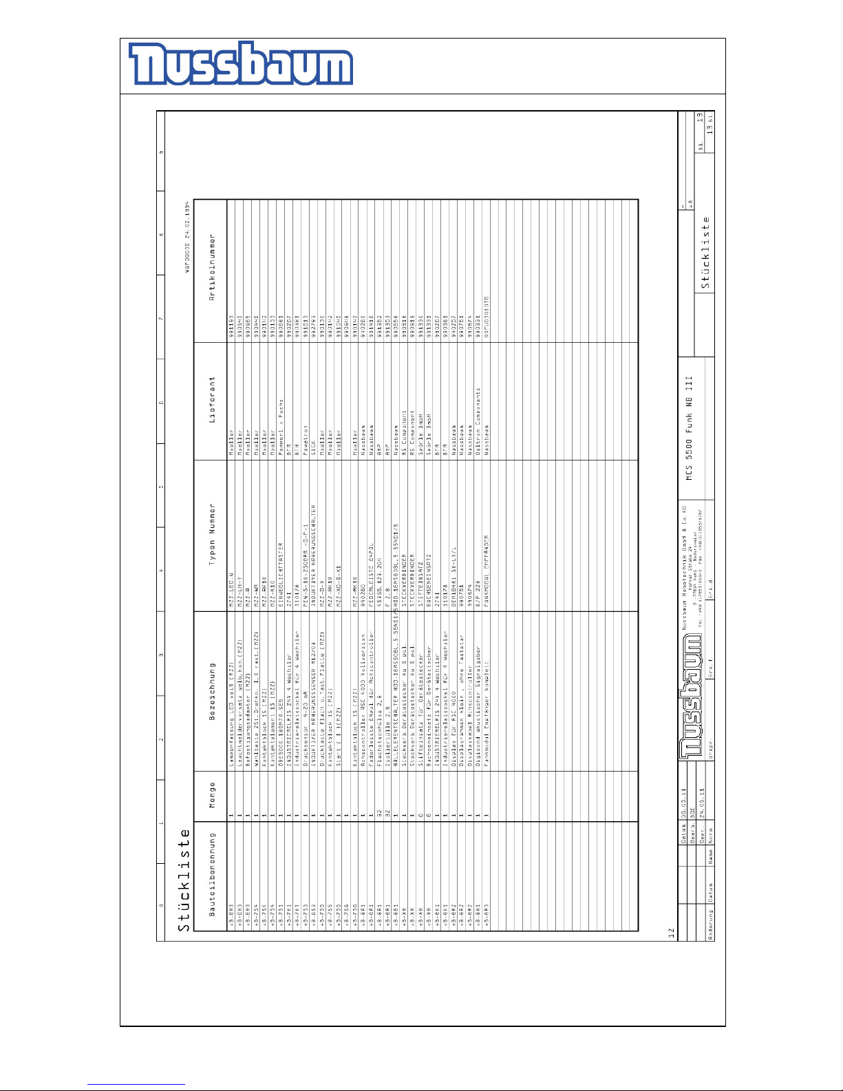
Operating Instruction and Documentation
MCS 5500 ND WIRELESS
- 57 -
 Loading...