

Nussbaum ATT BM 15 Touch, ATT BM 45, ATT BM 11 Touch, ATT BM 30-2, ATT BM 40-2 Technical Instructions
...Page 1
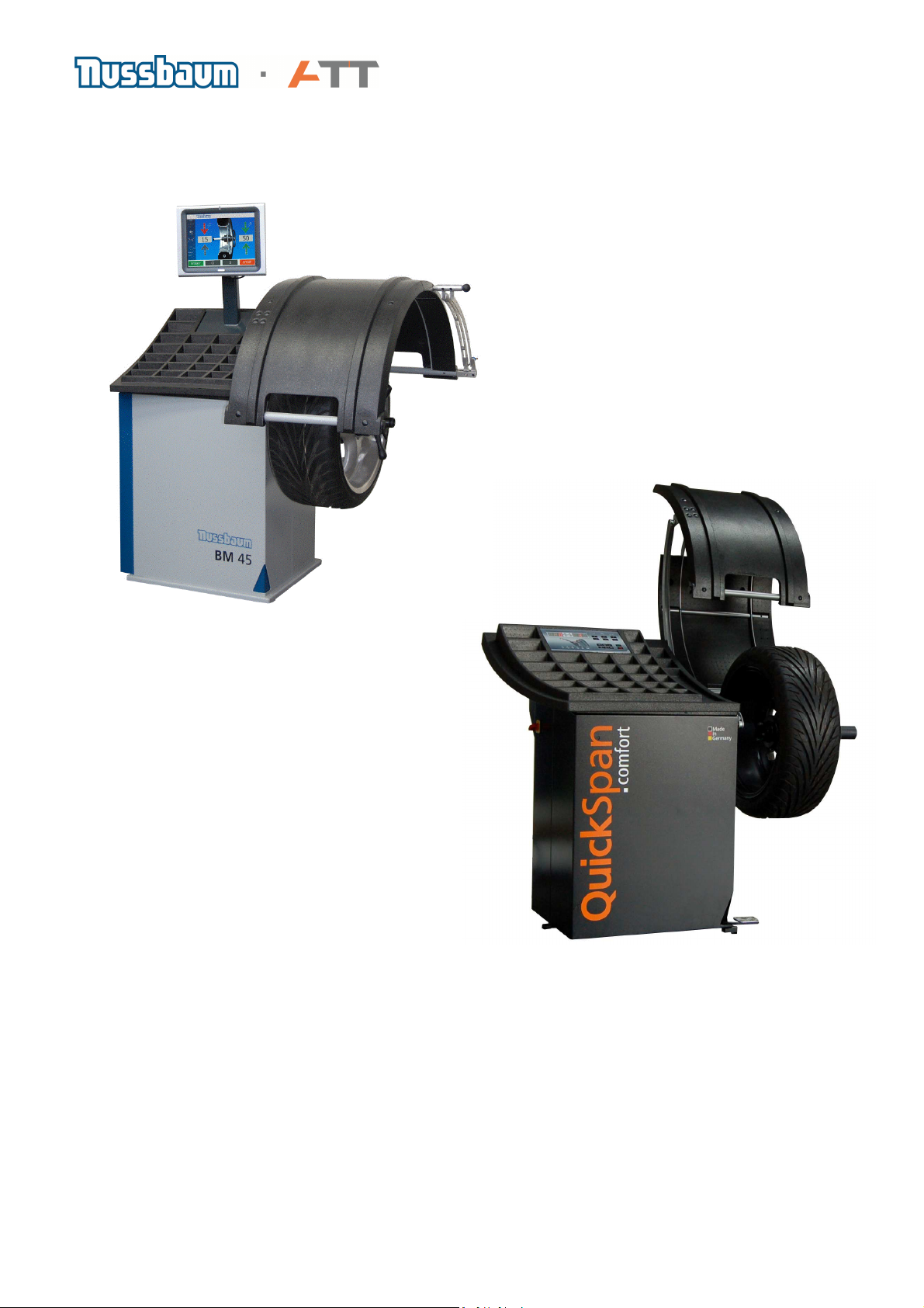
Technical Instructions
BM Wheel Balancers – new generation from Oct 2010
Status: 27. August 2013
Page 1 of 54
Page 2

Page 2 of 54
Page 3

Content:
1. Recommended spare parts list ................................................................................................... 4
2. General information on servicing machines.............................................................................. 4
3. Drive belt ...................................................................................................................................... 5
4. Main switch .................................................................................................................................. 6
5. Motor ............................................................................................................................................ 8
6. Piezo sensors .............................................................................................................................. 9
7. Opto encoder-printed circuit board .......................................................................................... 10
8. Motor control board................................................................................................................... 11
9. Basic board ................................................................................................................................ 13
10. Drive belt pulley ..................................................................................................................... 16
11. Wheel guard micro switch ..................................................................................................... 17
12. Potentiometers ....................................................................................................................... 18
13. Software update basic board ................................................................................................ 21
14. Software update Touch PC .................................................................................................... 25
15. Service Functions .................................................................................................................. 26
16. Mid centring device (NOT QuickSpan) ................................................................................. 34
17. QuickSpan .............................................................................................................................. 35
18. Foot pedal (QuickSpan) ......................................................................................................... 36
19. Maintenance unit (QuickSpan) .............................................................................................. 37
20. Repair Instructions for clamping fingers (QuickSpan) ........................................................ 38
21. Using UNI-LUG and Motorcycle adaptor on QuickSpan ...................................................... 41
22. Trouble shooting and problem solving ................................................................................ 47
23. Electrical schematic layout ................................................................................................... 51
24. Dimensions ............................................................................................................................ 53
25. Technical data ........................................................................................................................ 54
Page 3 of 54
Page 4

1. Recommended spare parts list
A suggested list of spare parts is recommended to be kept at the customer’s location in order to
rectify problems that might occur more quickly. A list below is also provided on our home page.
1987009WH7A POTENTIOMETER Distance + Diameter with cable
1987009WH9A POTENTIOMETER with cable for outside gauge
1987009WH4A Wheel guard switch
1987009WN3A FORK LIGHT SENSOR with cable
1987009WH2A TRANSDUCER SENSOR complete with cable
1987009WB7A MOTOR with brake
1987009WB5A MOTOR without brake for BM 11, 15 Touch, QuickSpan champ
1987009WD3A PRINTED-BOARD ASSEMBLY for BM 30-2, BM 40-2,
QuickSpan comfort, QuickSpan chrome
1987009WD3A PRINTED-BOARD ASSEMBLY for BM 11, QuickSpan champ
1987009WD2A PRINTED-BOARD ASSEMBLY for Touch PC
1987009WA7A Motor control unit complete for BM 11, 15 Touch
1987009WA8A Motor control unit complete for BM 30-2, 40-2, 35 Touch, 45 Touch,
all QuickSpan models
1987009W8MA Mid centering device QuickSpan complete
1987009W8LA Repair kit QuickSpan „Fingers“
1987009W8NA Repair kit pneumatic cylinder QuickSpan
2. General information on servicing machines
a) Repairs and servicing should only be carried out by qualified personnel.
b) Safety procedures:
Before opening the cover to the electronic parts switch off the main switch and remove the
electrical plug. Take special care not to touch the heat sink on the power control board of the
monitor machine versions because this holds a constant voltage of 230V, or 110V when the
machine is connected to the mains!
Never leave a machine unguarded, which has open electrics parts!
Before a machine is brought back into operation after repairs, ensure that no tools or components
are in contact with the rotating parts of the main shaft.
c) Make sure that a zero run and a calibration has been carried out every time after the machine
has been serviced or adjustments have been made to internal components!
d) Should components fitted to other parts e.g. the electronic boards become defective, do not try
to replace these yourself (except for fuses). If the machine is still in under warranty, the complete
board should be changed. A loss of warranty will occur if any alterations are made to individual
components!
Page 4 of 54
Page 5
e) Use only original parts to avoid the problems arising from using parts not having the correct
technical specifications or which have no guarantee for this machine. Corresponding spare parts
can be found in the spare parts document as well as finding it on our home page.
3. Drive belt
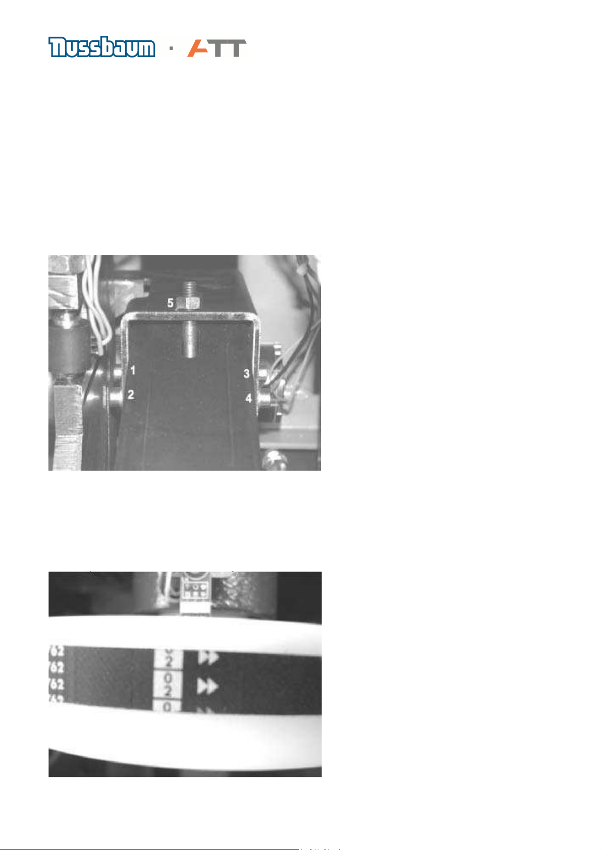
a) In order to replace the drive belt, loosen four bolts (1- 4). Next, loosen the tension bolt (5) to
allow the motor to pivot towards the belt pulley. Take off the belt. Replace with a new belt being
careful to make sure that the belt is as close as possible to the main shaft assembly to allow it to
fit correctly onto the small drive pulley. Tighten the tension bolt (5) and then the four mounting
bolts (1-4). Make sure that the tension on the belt is sufficient to allow 1cm
b) The direction arrows on the drive belt have no role to play because the rotation of 150 rpm for
the main shaft is very low. Direction arrows can be ignored.
(Drive belt, Art.Nr. 1987009WK1A)
c) Noises coming from the belt do not affect the results on the machine. Do not use grease or oils
to lubricate otherwise the loss of friction on the pulley could alter the rotational speed of the main
shaft.
Page 5 of 54
Page 6
4. Main switch
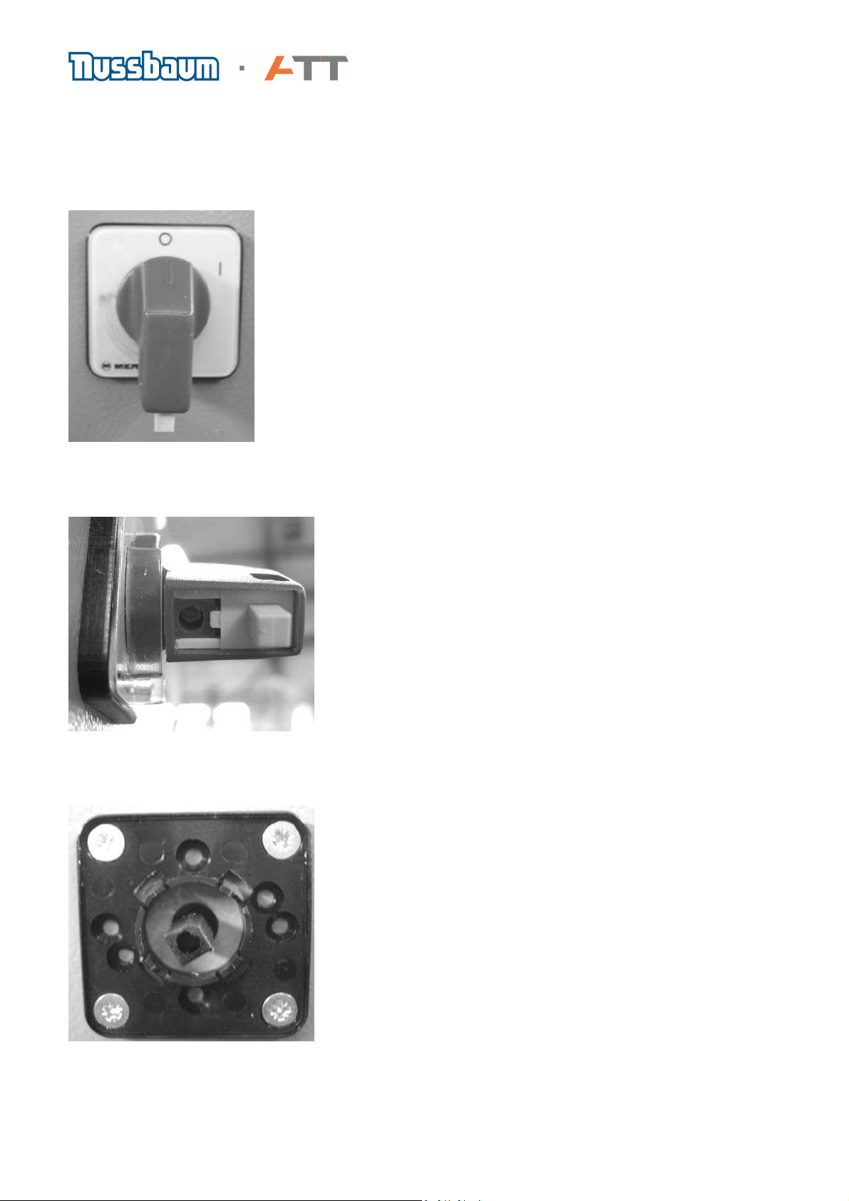
a) The main switch can be found on the left side of all machines. It can also be used as an
emergency off switch. Before any repairs are carried out to the machine please do not forget to:
DISCONNECT MAINS PLUG!
b) In order to remove the main switch, loosen the small screw as seen in the picture and pull on
the lever.
From the outside you will now see four screws on the cabinet wall, which secures the main body
of the switch. Loosen these screws to remove the element.
Page 6 of 54
Page 7
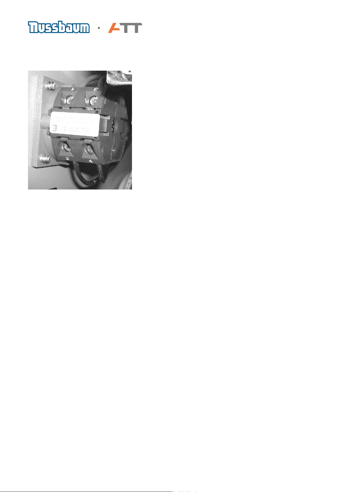
The next picture shows the inside of the cabinet with the main body and two of the four screws.
On the main body are four electrical connections numbered 14 which are the in and out going
power lines to the main switch.
Contact 1 is the outer conductor and contact 3 is the Neutral wire which is connected to an earth
plug. Contact 2 is the inner conductor and is protected by fuse X1-F1. Contact 4 connects to the
neutral connection X1. (If in doubt, please check wiring diagram)
Page 7 of 54
Page 8
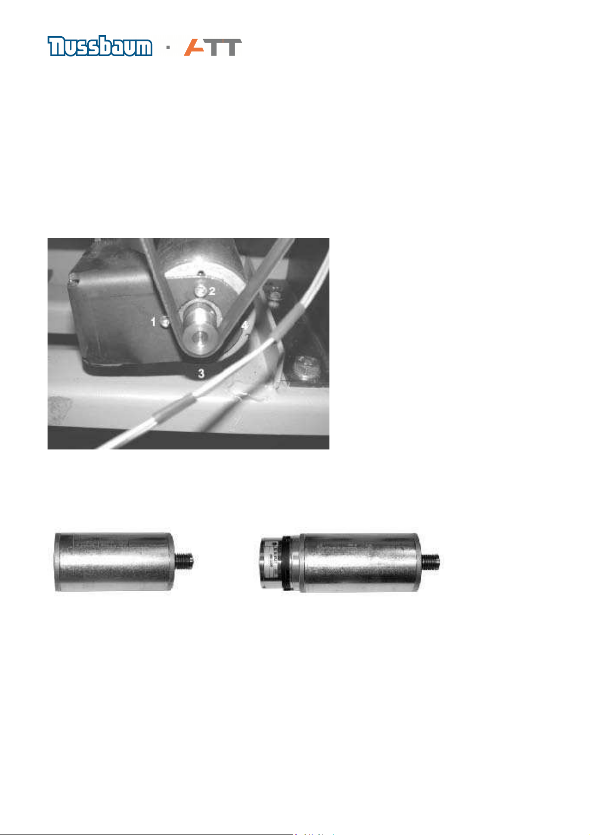
5. Motor
a) Disconnect the red and black motor cable at the point (J2-2, J2-3). In addition if the machine is
a model (above BM30) also disconnect the two grey brake leads at the point (J4-2, X1-3).
b) Loosen the drive belt as described in Para. 5. Loosen the securing screws(1)
(4) to remove the motor. Place new motor in position and tighten the screws (1)-(4).
Replace the drive belt as described above and replace the electrical cables.
c) Note: When ordering new motors make sure that the correct motor for the specific kind of
machine is chosen.
DC motor (24V) without braking capability for BM11, BM 15 Touch and QuickSpan champ and a
DC motor (48V) with braking capabilities for all from BM 30 upwards.
Photo. Shows motor without brakes Photo. Shows motor with brakes
Art.Nr. 1987009WB5A Art.Nr. 1987009WB7A
Page 8 of 54
Page 9
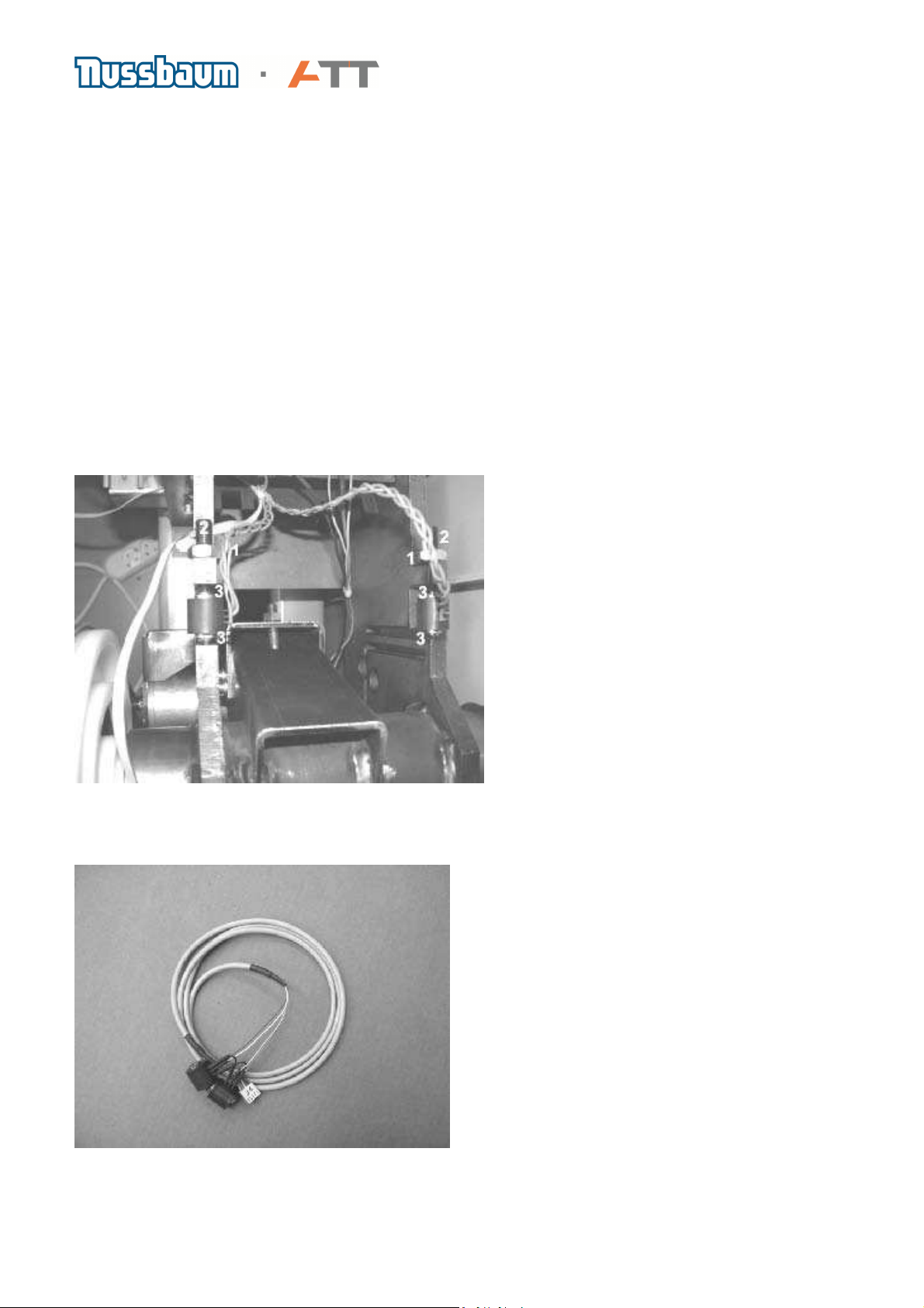
6. Piezo sensors
a) Disconnect the connecting lead J6 from the Basis board. Loosen the pies sensor securing nut
(1) and screw out the securing bolt (2) using an Allen key. Please note that on machines built from
August 2011 the screw of the sensor is secured inside the thread with Loctite
Look out for the four ball bearings (3) at either end of the piezo sensors. To replace the sensors,
first clean and then put a small dab of grease into the socket spaces for the ball bearings, clen the
thread from remaining Loctite, put medium type Loctite on the screw and place the Piezo sensor
gently into position.
Return each piezo sensor with the ball into position and screw on the sensor securing bolt making
sure that the ball is also in position. Tighten the securing bolt to 2Nm. Do not over tighten the
sensors and tighten the securing bolts alternately.
Replace the securing nut and finally re-connect the leads to the basis board at the point J6.
b) The piezo sensors always come as a set with balls and a single shared lead connecting to a
plug. They can be fitted in any position i.e. front, rear, left or right without any adverse affects on
results. After replacing the sensors, it is imperative that a zero run and calibration are carried out.
Photo shows Piezo sensors (Art.Nr. 1987009WH2A)
Page 9 of 54
Page 10
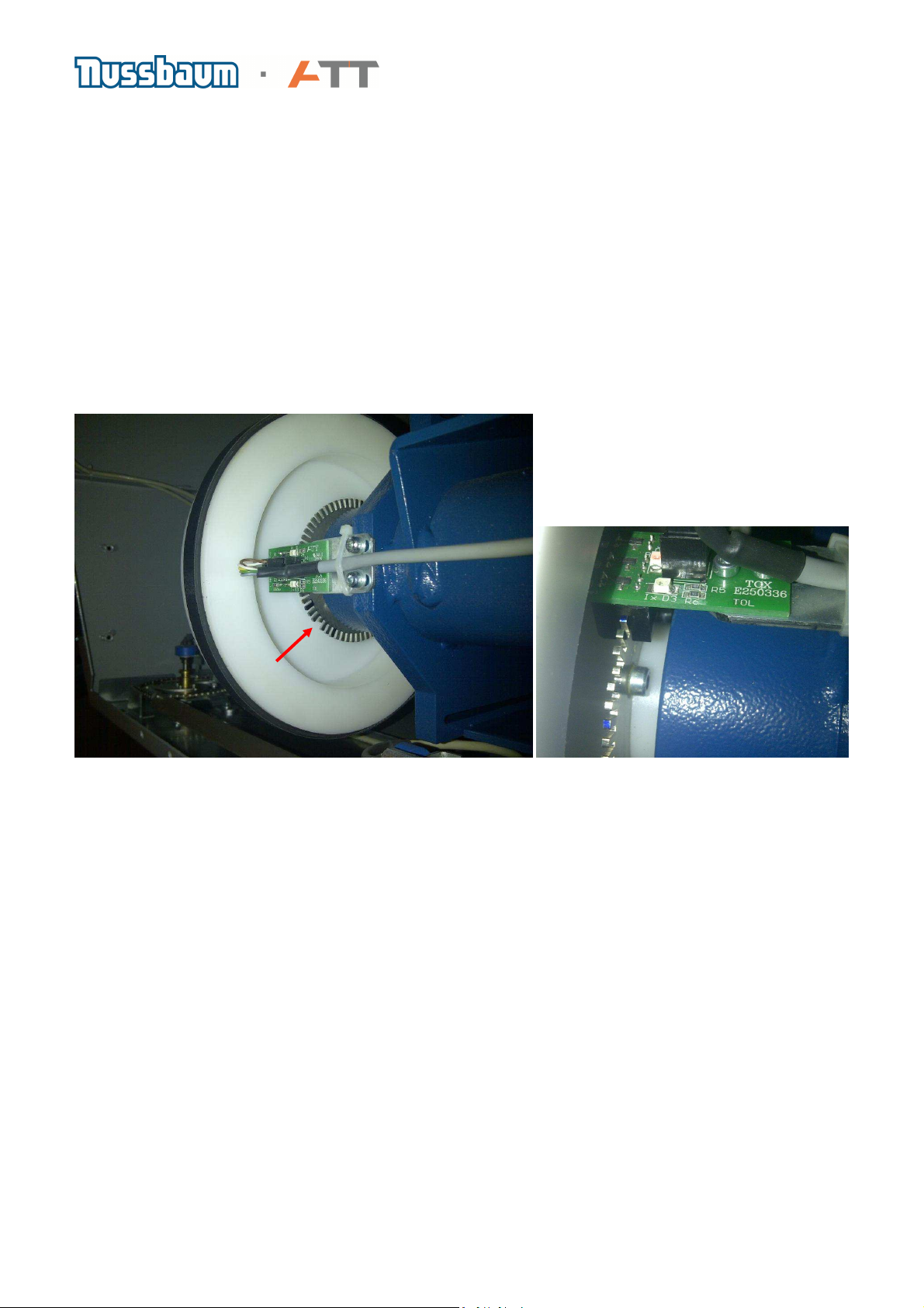
5
4
3
2
1
7. Opto encoder-printed circuit board
a) There are three red light diodes on the opto encoder printed circuit board. When these three
light diodes are blinking during the operation of the machine, it means the opto encoder is
functioning. If the machine is switched on (CAREFUL VOLTAGE) and the main shaft is turned
slowly, the blinking of the diodes can be observed.
b) To remove, unplug the lead at J2 on the basis board. Loosen the securing screws (1) enabling
the metal support (2) with the opto encoder board to be withdrawn from the machine. Unscrew the
opto encoder board (3) from metal support and replace with another. Return metal support with
opto encoder into position and secure. The opto encoder board must not make any contact with
either the toothed disc (4) or the drive pulley (5). Finally re-connect the plug
c) Note: If a new opto encoder board has been fitted and the position for placing weights cannot
be found, then the actual angle of the opto encoder in relation to the toothed disc should be
checked. As seen in the upper picture, the sensor should be at 90° to the drive pulley
d) If you check the toothed disc, you will find a position where there is a small gap (See red arrow
in the picture above). This position is measured by the opto encoder as Zero point. The toothed
disc has 256 segments and by selecting function F9 on an LED machine you can see the number
of each segment as the main shaft is turned. With monitor machines, the same function can be
checked in the service screen reading from the bottom left of the screen. If the main shaft is
turned a complete revolution in a clock wise direction the scale will count from 0 to 255 and
likewise opposite in a counter clockwise direction.
Page 10 of 54
Page 11
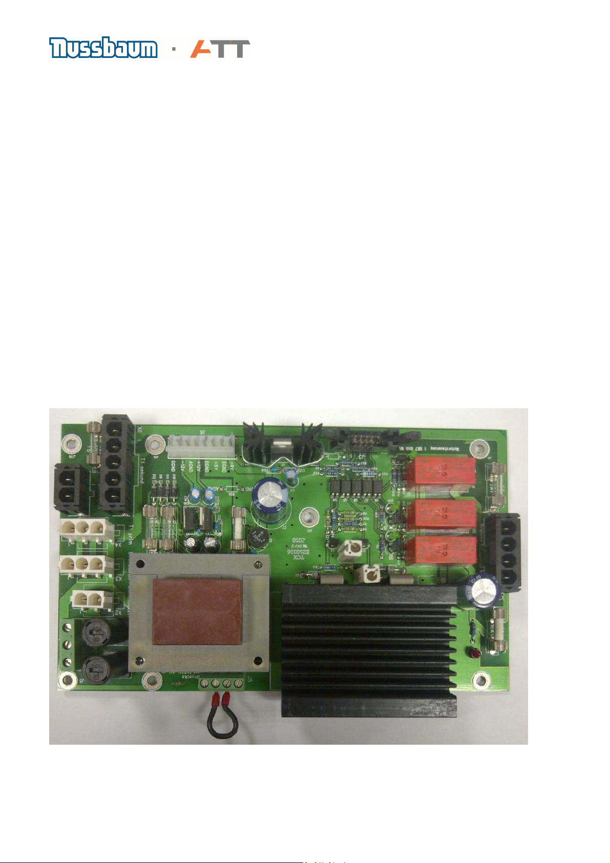
X 7
J 3 J 6
X 1
X 6
X 4
X 5
D 1
J 5
Brake
QuickSpan
Motor
F5 -
Brake
F1 -
Motor
F6 -
QuickSpan
8. Motor control board
a) The motor controller board works in conjunction with the transformers (located on the lower
side of the board to make up the power supply for the balance machine. To remove the motor
controller board, unplug the connected cables and loosen the securing screws. Replace a new
board opposite to the method of removing.
b) Overview of the symbols printed next to the relevant connections:
J3 Control line basis board -> Motor controller board
J5 Bridge 115 V / 230 V input voltage
J6 Power supply to the basis board
X5 Mains supply
X4 Connection to primary side of transformer (located below motor control board)
X5 QuickSpan
X6 Connection to secondary side of transformer (located below motor control board)
X7 Motor and Brake
c) The red LED D1 indicates whether 24VDC or 48VDC is available. The LED will stay illuminated
even when the machine has been unplugged from the mains because the power supply unit
contains a filter capacitor. The light can also illuminate when the motor is turned as it acts like a
generator and so charges the capacitor with electricity simultaneously.
More information on fuses see chapter 22
Page 11 of 54
Page 12
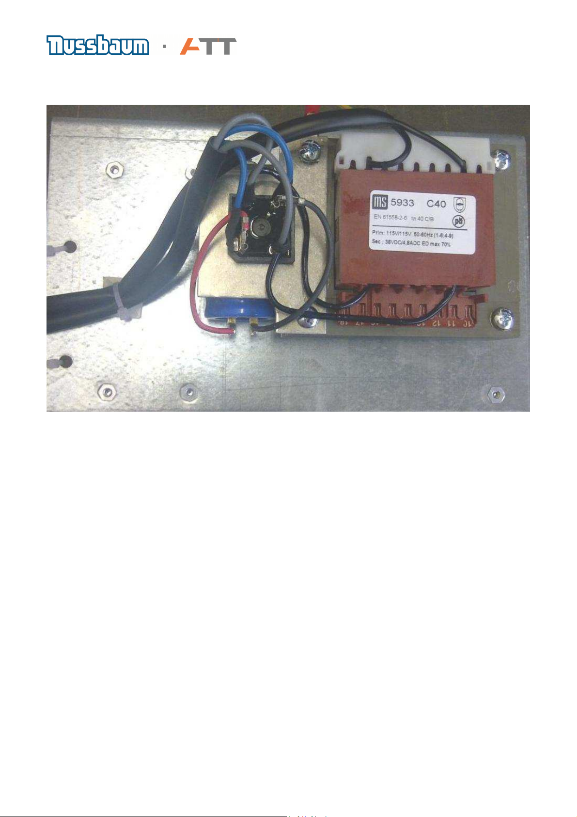
Transformer
Capacitor
AC / DC Bridge
Motor control board lower side
Page 12 of 54
Page 13
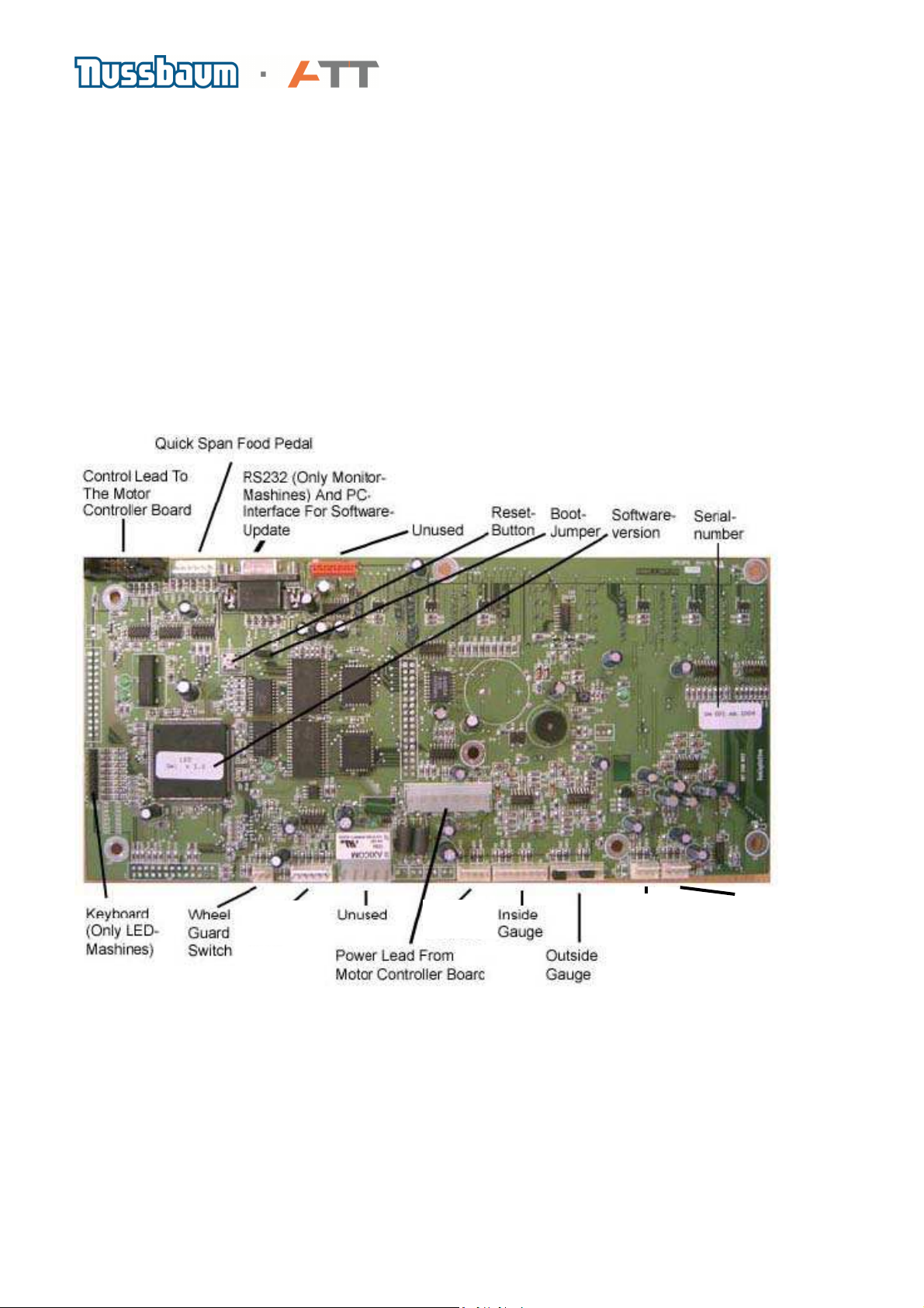
Temperatur
Unused
Piezo
Sensors
Opto
Encoder
9. Basic board
a) The basic board evaluates and saves all the measurement values and software as well as
controlling the standard electronics. Light diodes can be found on the underside side of the board,
which provides the display for the LED machines. The board is secured to an aluminium plate on
one side and a keypad on the other. On the monitor machine, the basic board is located on the
rear wall of the cabinet to the right side of the PC printed board assembly.
b) To exchange, unplug all leads, remove the board and replace returning the leads to the same
positions.
c) After exchanging a basic board, all measurement values data is lost and so it is important that a
zero run and calibration are carried out.
sensor
Generally, the basic board is already flashed with the most up to date software before leaving the
factory, which is why it is very important to note the type and serial number of the machine before
ordering a new board.
d) There are two jumpers plugged into the pins of the connector J12 for the outside gauge as
seen in the photo above, displaying the positions (1-2 and 5-6) they should be in on all machines
except BM 40-2, BM 45 Touch and QuickSpan chrome. From BM40-2 upwards this plug is used
for the outside arm and so the jumpers would have to be removed!
Page 13 of 54
Page 14
e) The list below shows a summary of all the connectors on the basis board with their codes
which are marked next to each connector on the board.
J1 Key pad (only LED-machines)
J2 Piezo-sensors
J3 unused
J4 unused
J5 Wheel guard micro switch
J6 Opto encoder printed circuit board
J7 unused
J8 Potentiometer for Distance and Diameter
J9 Main power supply coming from Motor controller board.
J10 unused
J11 Temperature sensor
J12 Potentiometer 3 outside arm (from BM40)
J13 Boot-Jumper for Service update of the Software
J32 Foot pedal switch (QuickSpan)
f) When removing the basis board from the aluminium plate, please be careful not to bend the
ribbon cable as it can be easily damaged and cause the machine to function improperly.
Page 14 of 54
Page 15
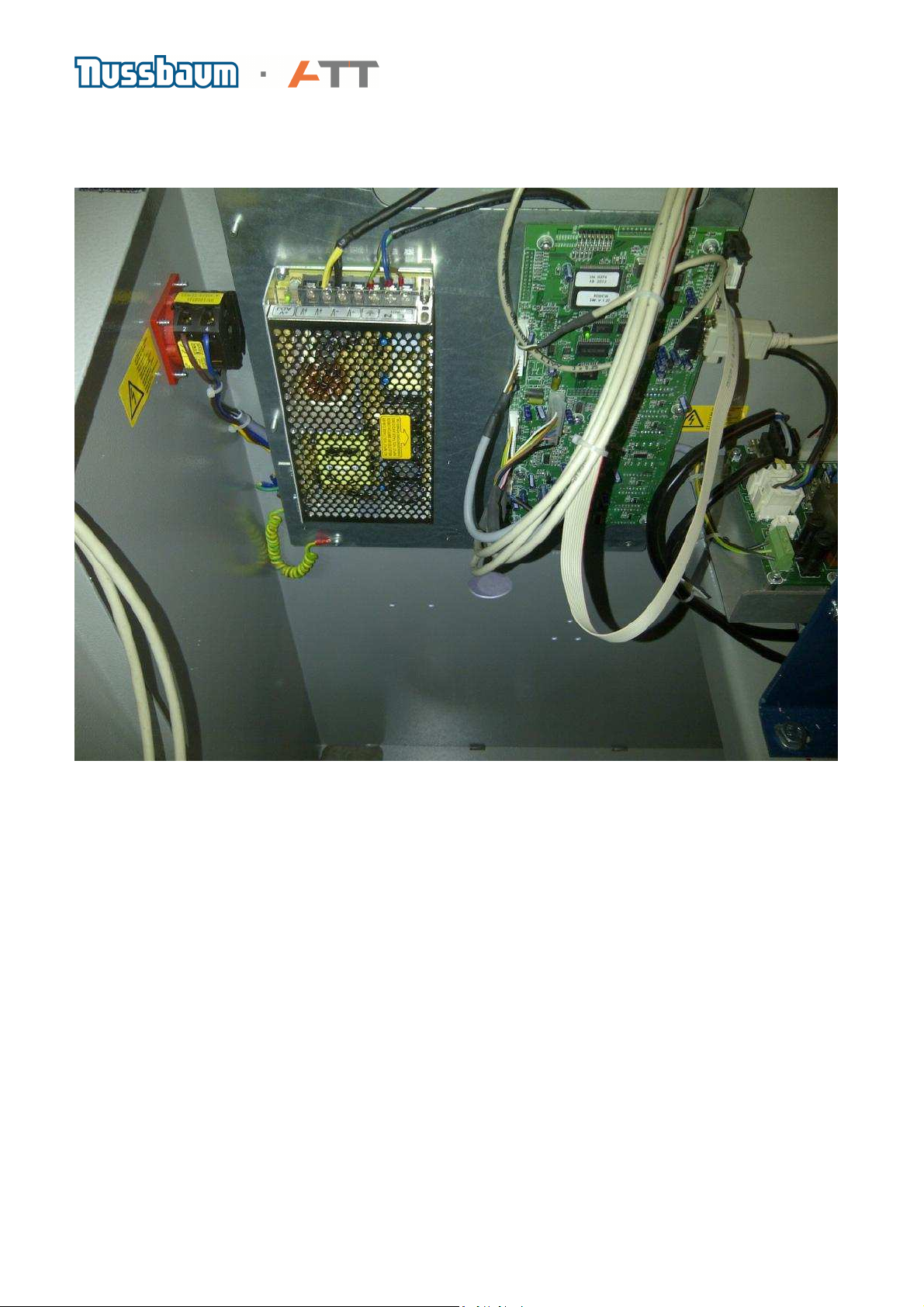
2
1
On the Touch PC machines the basic board (1) is located inside the machine and mounted on a
panel together with the power pack (2) for the Touch PC
Page 15 of 54
Page 16
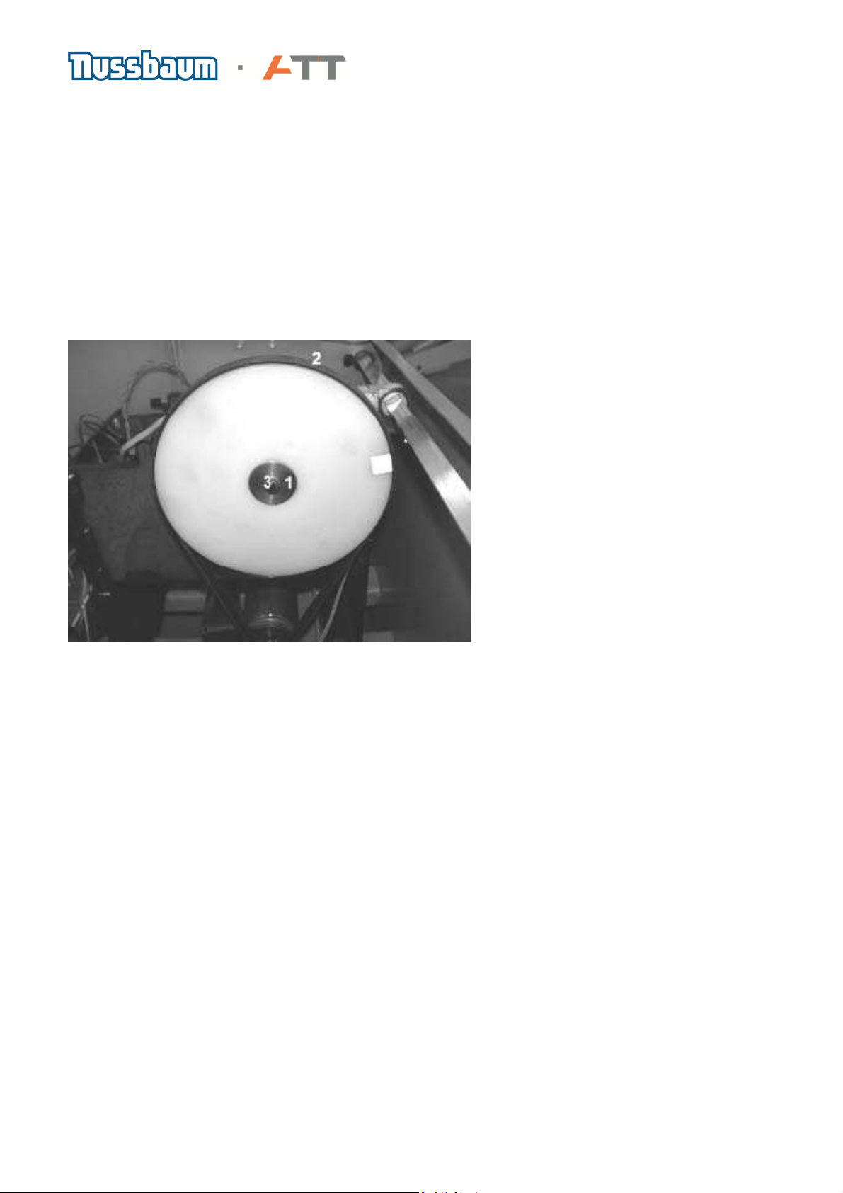
10. Drive belt pulley
b) To exchange the belt pulley, take off the drive belt and then the screw (3) to enable the pulley
to be taken off the main shaft.
When removing the pulley be careful not to lose the small groove spacer. On fitting a pulley this
small groove spacer has to fit into the groove in the centre of the pulley.
The bolt (3) should then be tightened to exactly 9Nm using a torque wrench. Loctite (medium
type) should also be used to secure the bolt by applying it to the complete length of the threads.
Finally check that the Calibration point (indicator) on the main shaft is in line with the index.
Page 16 of 54
Page 17
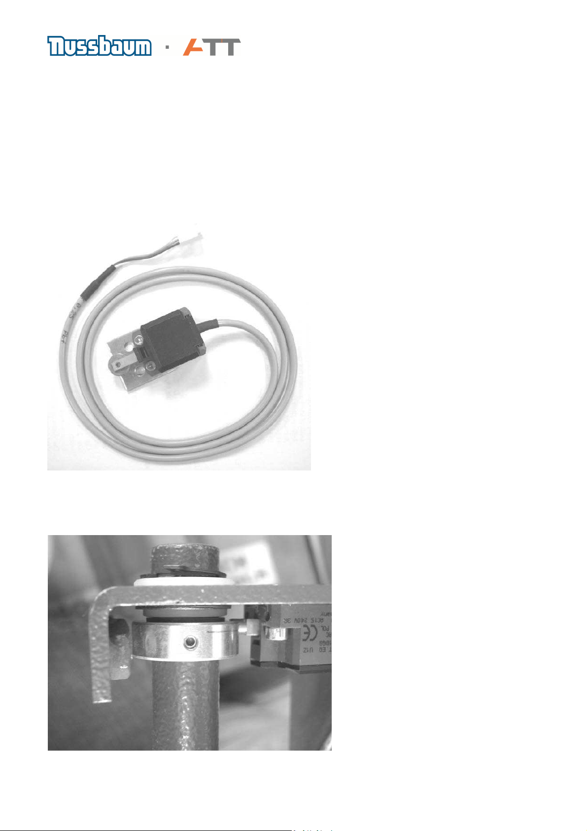
11. Wheel guard micro switch
a) The micro switch relays the position of the wheel guard. Because this process is controlled by
the software, it can be switched off. In this case, any problems arising should first be checked by
noting the functions set by the user with function F8.!
b) To remove, first take out the lead from the connector J5 on the basic board. Loosen the screws
on the switch and remove. Replace the new switch with the wheel guard in an upright position
enabling the contacts J5-1and J5-3 to be connected and in the same case contacts J5-2and j5-3
to be connected with the wheel guard closed.
(Wheel guard micro switch Art.Nr. 1987009WH4A)
c) If the case arises during transport that the camshaft becomes loose as in the photo below, then
re-secure the spring clip by closing the wheel guard so as to align the camshaft with the wheel
guard.
Page 17 of 54
Page 18
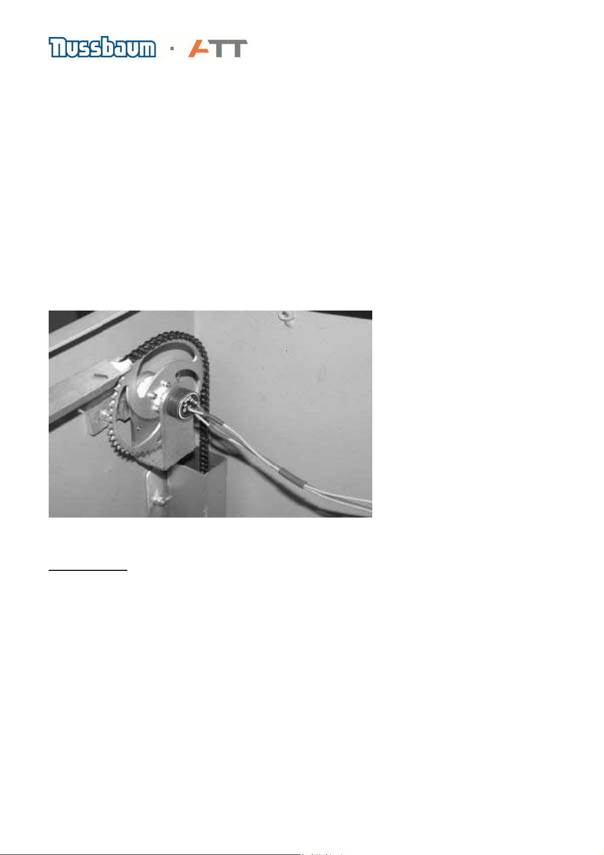
12. Potentiometers
a) Up to three potentiometers can be fitted, depending upon the type of machine.
P1 is the potentiometer at the centre of a chain pulley to measure the distance from the edge of
the machine to the first weight position and depending on the type of program selected, the
second weight position. The potentiometers have a value of 10kOhm/20%/340°.
b) The potentiometers have an internal mechanical stop position, which is important to note when
fitting them to the relevant gauge. The movement of the gauge should not be greater than the
stop position otherwise it could damage the potentiometer. The distance potentiometer is
connected to J8-1to J8-4. In order to remove it, the complete chain pulley and chain should be
removed by loosening the screws securing it to the cabinet wall. When replacing a potentiometer
into the chain pulley, make sure that the potentiometer spindle is turned anti clockwise to almost
the position stop. Thereby, when the chain pulley is fitted together with the potentiometer, they will
be able to both turn clockwise to the chain pulley position stop
The contact no. 1 on the potentiometer take the white coloured wire and no. 2 the green wire, with
no. 3 taking the brown wire.
Contact colour 1 ws 2 gn 3 bn
c) Note: Make sure that while fitting the chain, the gauge is in the home position and the chain
pulley is at the stop position shown by the screwed bolt on the pulley contacting a limit stop. The
potentiometer spindle should also be shortly before the left hand mechanical stop position.
Page 18 of 54
Page 19
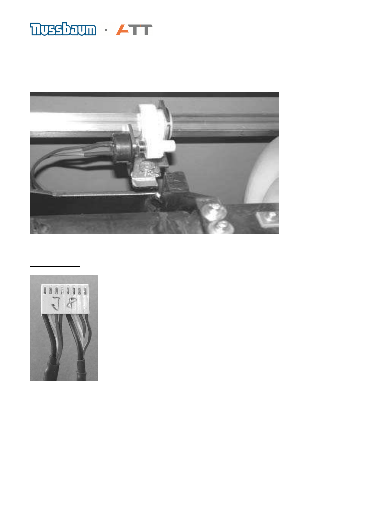
d) The potentiometer measuring the diameter gauge is connected from points J85 to J8-8. When
exchanging please make sure that the potentiometer is turned anticlockwise before fitting.
Important: the end of the gauge should be resting on the top of the main shaft housing during
replacement to allow minimum and maximum measurements to take place for all types of wheel
The contact no. 1 on the potentiometer take the white coloured wire and no. 2 the green wire, with
no. 3 taking the brown wire.
Contact Colour 1 ws 2 gn 3 bn
The photo shows connection plug J8. Connected to it are the leads from Potentiometer P1 for the
distance gauge (right side)and P2 for the wheel diameter (left side from BM 20 upwards) The
colour code order of wires on P2 is black, white, green and brown. For P1 on the other side is also
black, white, green and brown.
Page 19 of 54
Page 20
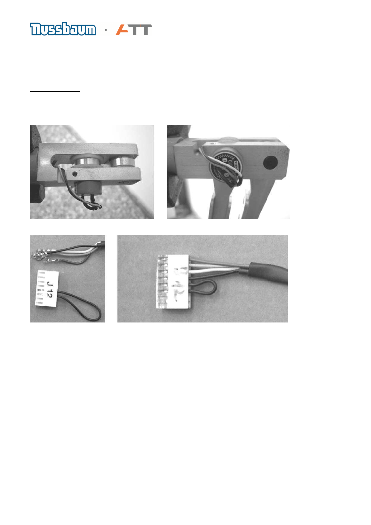
e) The potentiometer for the width (outside arm) is connected to J12-1 to J12-4. In order to
exchange the potentiometer these wires should be soldered onto the new one.
The contact no. 1 on the potentiometer take the white coloured wire and no. 2 the green wire, with
no. 3 taking the brown wire.
Contact Colour 1 ws 2 gn 3 bn
The reason why the wires need to be soldered is that the plug for the basic board cannot be
passed through the tube of the wheel guard and so it has to be removed.
The photos show the position of the potentiometers for the outside arm
The left photo shows the plug J12, which takes the leads coming from the outside gauge. On the
right shows the leads, soldered onto the plug in the order brown, green white and black.
Page 20 of 54
Page 21

13. Software update basic board
a. General:
The software concept is based on using Flash ROM memories, which allows the machine to start
quickly after the operator turns on the main switch. To install the software on the flash memory
(flash) you need an application which includes the complete flash process. This makes sure that
the software transfers quickly and safely and to the hardware destination remains there.
Additionally this application makes it possible, to install new software functionalities on the current
machine at any time, without exchanging any tool.
The software as well as the flash tool can be downloaded from the exclusive area (Infocenter) on
www.nussbaum-group.de
CAUTION:
Make sure that the software for the Touch PC is always updated FIRST
b. System requirements:
System software: Windows XP or Windows 7
• Memory required: 1MB main board memory; max. 0,6MB RAM
• Resolution: minimum of 800x600 pixel Equipment
• The PC / Laptop needs a serial interface (RS232)
c. Start the program:
The program „Flash tool Vxxx.exe“ (xxx is for the version number of the flash tool) should be
copied from the CD on your PC/laptop before you start the program. It starts with a double click
on the program symbol.
Comment: If the program starts with the CD, the trails and data name of the data file who has to
be flashed will not be saved. You have to re-select it after every start of the program.
(see chapter 14)
Page 21 of 54
Page 22
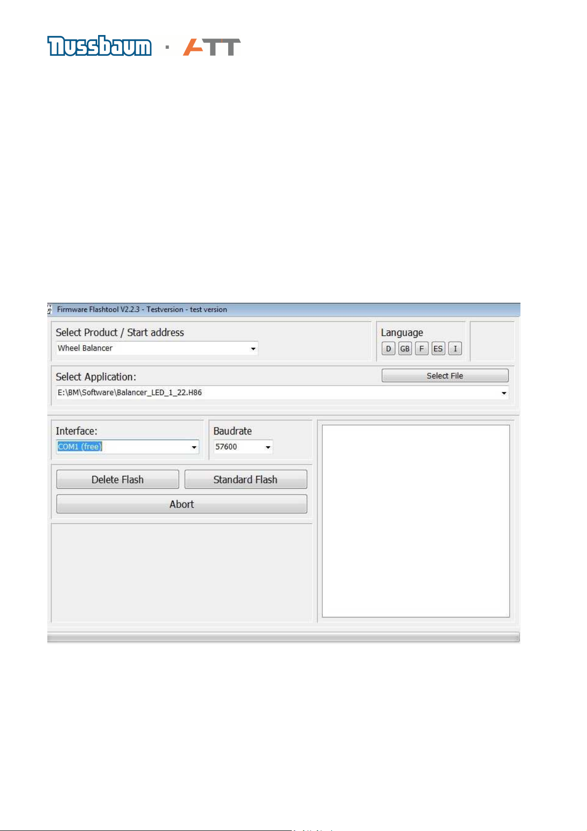
d. Screen layout:
1 Program-title bar for instance with the name of the program and version
2 Product selection: Here you select the product on which you want to actualise the software
3 Selection of application: Shows the trails and names of the data that has been selected and
transmitted by flashing procedure. The last 5 selected data’s are available.
4 Deletes the flash memory, means prepares the software to install
5 Cancelled the flash procedure
6 Is to select the interface for which should be flashed
7 Here you select the Baudrate (speed) for the data transfer
8 Here you can select the data who has to be flashed
9 Starts the standard flash procedure with the under 3 or 8 selected data
10 View window: Shows all necessary information
11 The progress display shows the current situation of the selected functions (delete/flash)
12 Select the language
1
6
3
4
2
12
8
7
10
9
5
11
Picture 1: The standard version of the flash tools
Page 22 of 54
Page 23
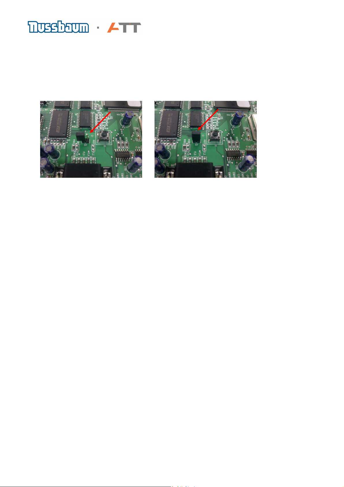
e. Description of the flash function:
Preparation basic board:
1. Shut down the machine
2. The jumper on the basic board on which the new software must been installed has to be
switched.
Picture 1: Picture 2
Jumper open for standard operation Jumper closed for Flash operation
Comment: on wheel balancers without monitor, the basic board is below the keyboard.
3. The basic board who has to been flashed must be connected with a customary serial cable
(Sib D9pins, 1 x plug in, 1 x connector) and a serial interface (see picture 3) on the computer
on which the flash tool is. Hereby it concerns about following description:
f. Preparing of flash tool
Start of flash tool:
The flash tool starts by a double click on „Flashtool_Vxxx.exe“. On the screen appears a start
window of the flash tool (picture 1 or picture 2)
Select the serial interface, on which you connected the serial cable. The serial interface „COM 1“
which is already pre-adjust should be correct, in other case with several serial interfaces please
select the highest or furthest on the left presented interface (see on the back side of the
computer). Otherwise select „COM 2“, „COM 3“ or „COM 4“
Select WHEEL BALANCER with „select product / start address“, if it is not already selected.
Select under "select application" your file or press the button " select file " and select the
catalogue with the file that has to been flashed.
Such a file is named "Balancer_LED_1_22.H86" or "Balancer_Touch_1_22.H86".
After you selected the file and with the button "open" confirmed this, you will see the trail and the
file name of the selected file under the writing: "select application".
Page 23 of 54
Page 24

Flashing of software / delete flash / cancel:
Depending on what you intend, one of the following 3 buttons should be pressed:
- Delete flash (4): If the complete flash memory should be deleted and prepared for the new
software, please press the button “delete flash”. This is necessary if the software has to be
installed for the first time on the basic board.
Do not delete the memory flash, if the current software should be updated.
- Standard flashing (9): If there exist already a software on the control board or if the flash
memory was earlier deleted through the "delete flash " button, then use the “Standard
flashing" button and the selected software afore will be flashed.
- Cancel (5): The current procedure (delete flash or standard flashing) can be cancelled
through this “cancel” button. Depending on the progress of the procedure, is it possible that
the software was already partly-implemented or not. If the blue progress bar you can still see
with the deletion of the flash memory in the left half and then if the "cancel" button is pressed,
the deletion of the flash memory will be cancelled. The deletion was not implemented at this
time yet. The software played afore is still available after the restart.
You can see the progress of the selected procedure at blue progress bar (11) down on the
screen. Depending on procedure, the progress goes faster or slower. After the start and before it
ends, the progress bar is a certain time available on a screen.
Right down in the white status field (10) will be shown a message, which describes the current
condition of the selected procedure. Here also error messages will be shown.
If a procedure was ended or cancelled, the reset button must be pressed on the control board
which is going to be flashed (e.g. S1 reset on the control board A1and/or S2 reset on the indicator
board A2 of the brake test stand) or the machine with the control board which is going to be
flashed must be switched off and on
g. End of the flashing procedure
The flashing procedure is completed, if the blue progress bar (11) disappears again, the buttons
are activated again and in the status field appears a message. The message gives information
whether the flashing procedure or deleting was successfully completed or not.
h. After flashing procedure:
• Switched off the machine
• The Jumper on the flashed board must be changed again. It can only be connected to one
contact/pin.
• The serial cable can be taken off again. The occupied during flashing procedure serial
interface, can be yet plug-in with the previous cable.
• For normal work with the new software the machine must be restarted.
Page 24 of 54
Page 25
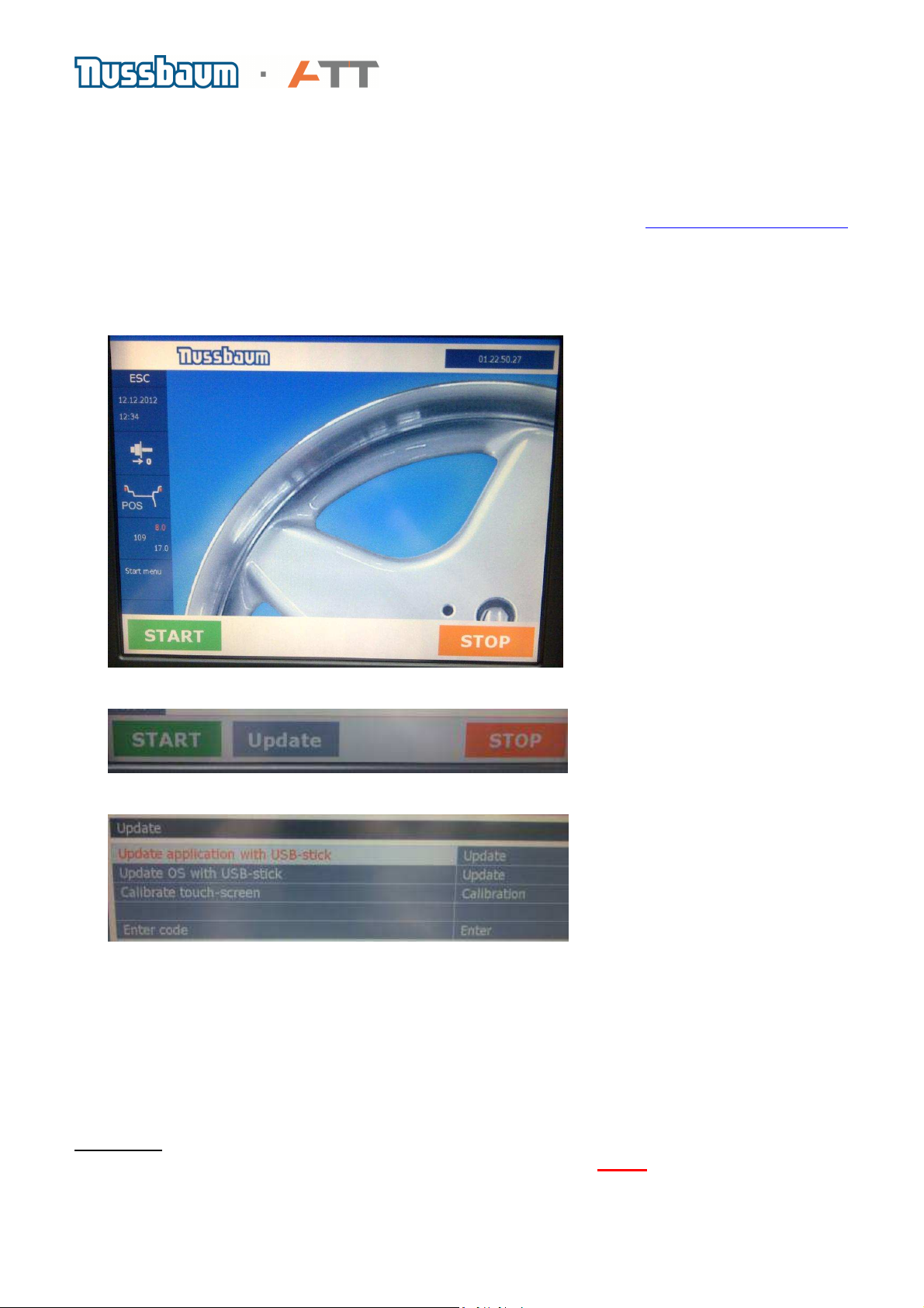
14. Software update Touch PC
The software for the Touch PC is available as a zip file that needs to be unzipped to a USB stick.
This zip File can be downloaded from the exclusive area (Infocenter) on www.nussbaum-group.de
− Switch the machine off, connect the USB stick to one of the USB ports on the lower side of
the Touch PC
− Switch the machine on
− Touch the field in the right upper corner of the welcome screen two times
− Touch UPDATE
− Select „Update application with USB stick
− Touch Update and confirm the update
− After the Update has been done switch machine off and remove USB Stick
− Switch machine on, software version in upper right corner of the first screen needs to show
the latest version i.e 01.22.50.27
− If the software on the basic board is not of the latest version an error message will be
displayed and the update of the software of the basic board needs to be performed in order to
bring the machine to work
CAUTION:
Make sure that the software for the Touch PC is always updated FIRST
Page 25 of 54
Page 26
15. Service Functions
The information on the service functions can also be found in the instruction manual
DIGITAL WHEEL BALANCERS
Via the function key you get into the menu for service functions to select the basic
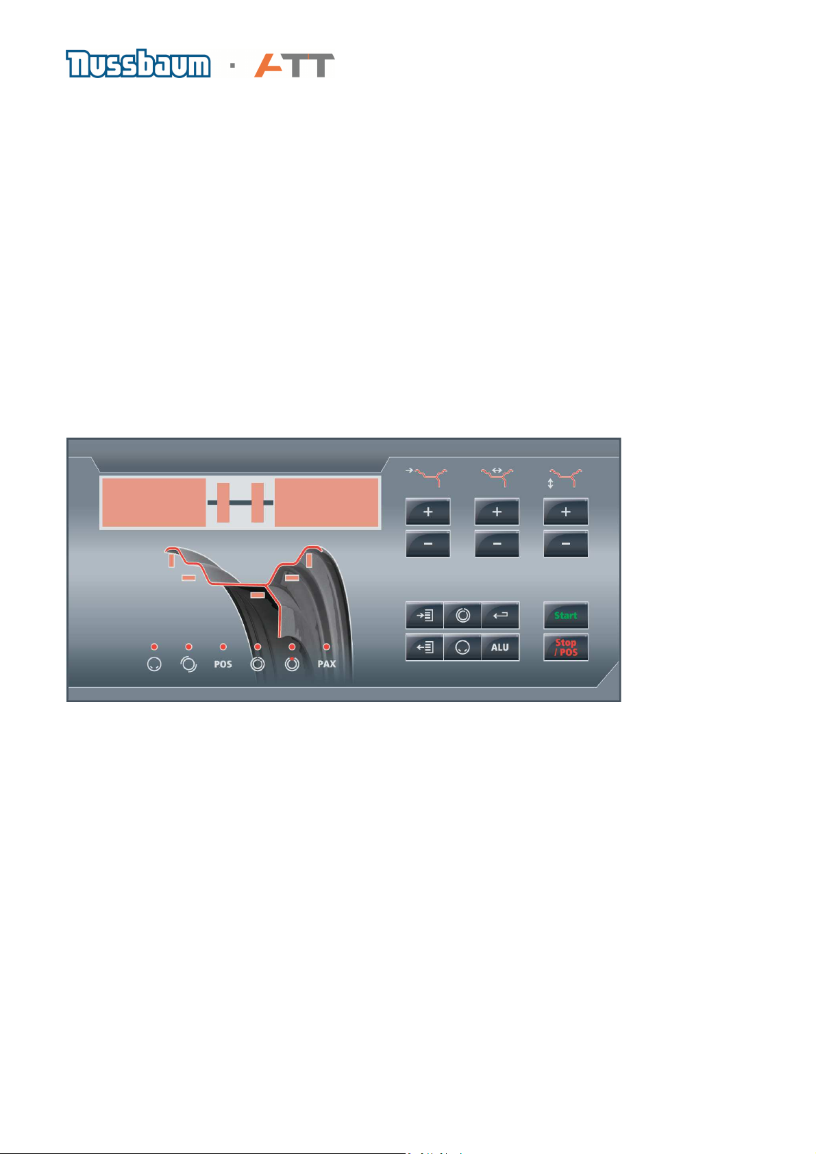
settings or change them according to the user’s requirements. The various menu functions from
F1 to F14 can be selected by pressing the +- keys
When you are in the function menu, an „Fn“ is shown on the left side of the digital display. The
chosen function is shown on the right side of the digital display.
Once a particular function is desired, it can be chosen by pressing the function key again
F1 Precision reading of 1 Gram
F2 Zero run
The Zero run is provided to electrically compensate the unbalance of the adaptor or clamping
means.
Whenever the clamping means has been dismounted and replaced a compensation of the
residual unbalance in the adapter and clamping means should be carried out.
Routine:
MACHINES with manual clamping of the wheel
Remove the cones and clamp from the adaptor.
Press the function key to select the function menu.
Use +/- keys to select the Function 2.
Press function key again to activate the function.
Press START to start the run.
The residual unbalance of the adaptor is calculated and saved in the
memory. (This value stays in the memory even after switching off the
power). After the run has finished, the program automatically changes
to normal mode.
MACHINES with QuickSpan:
Attach the pressure cup for steel rims to the clamping sleeve and
activate the QuickSpan
Press the function key to select the function menu.
Use +/- keys to select the Function 2.
Press function key again to activate the function.
Press START to start the run.
The residual unbalance of the adaptor is calculated and saved in
the memory. (This value stays in the memory even after switching
off the power). After the run has finished, the program
automatically changes to normal mode.
Page 26 of 54
Page 27
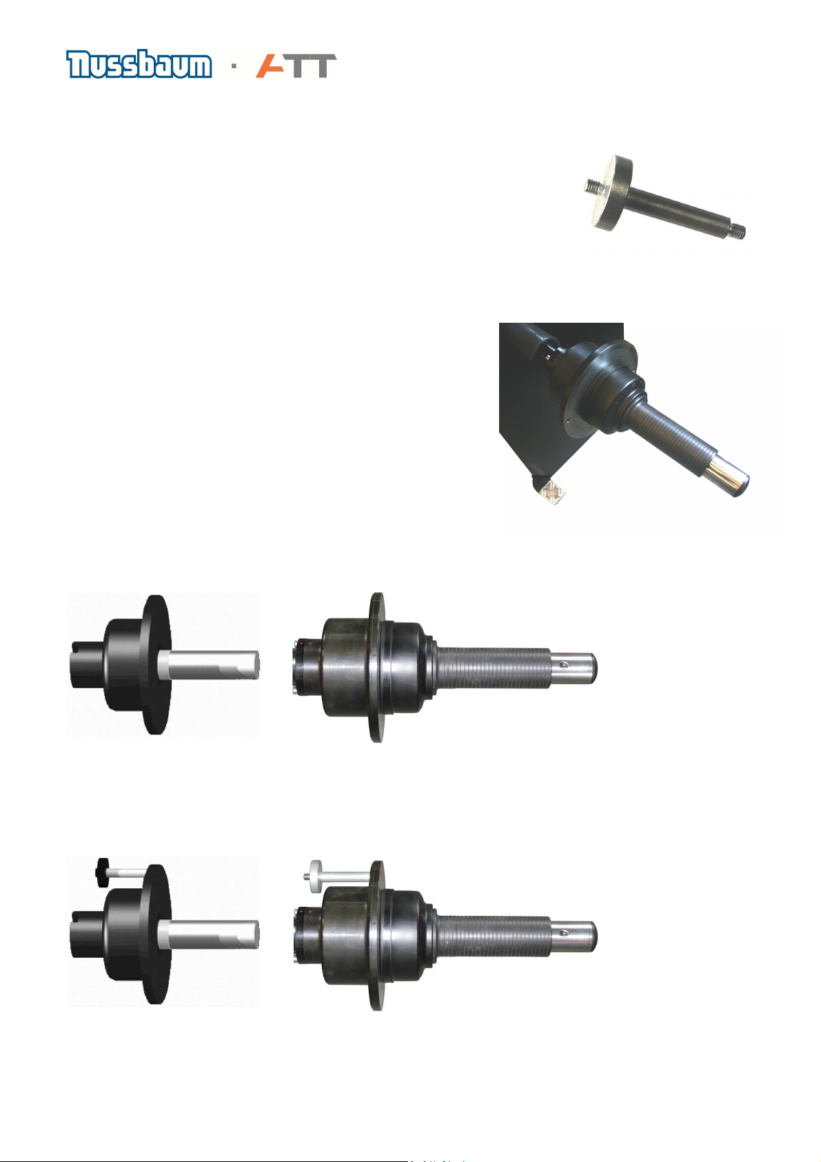
F 5 Calibration
The calibration weight supplied with the machine must be used
together with the clamping adapter. Make sure that the threaded hole
on the adapter is in line with the red indicator marking on the main
shaft.
For calibration the calibration weight (1987009WG3) is required
MACHINES with manual clamping of the wheel
Remove cone and clamp from the main shaft.
MACHINES with QuickSpan:
Attach the pressure cup for steel rims to the clamping
sleeve and activate the QuickSpan
Press the function key to select the function menu.
Use +/- keys to select the Function 5.
Press function key again to activate the function.
There are 3 measuring runs performed during the
calibration procedure, the wheel guard (if present) can be
left open:
1. Measuring run
Run without calibration weight
Machines with manual QuickSpan
clamping of the wheel
2. Measuring run
Run with calibration weight on the left side of the mid centering device
Machines with manual QuickSpan
clamping of the wheel
Page 27 of 54
Page 28
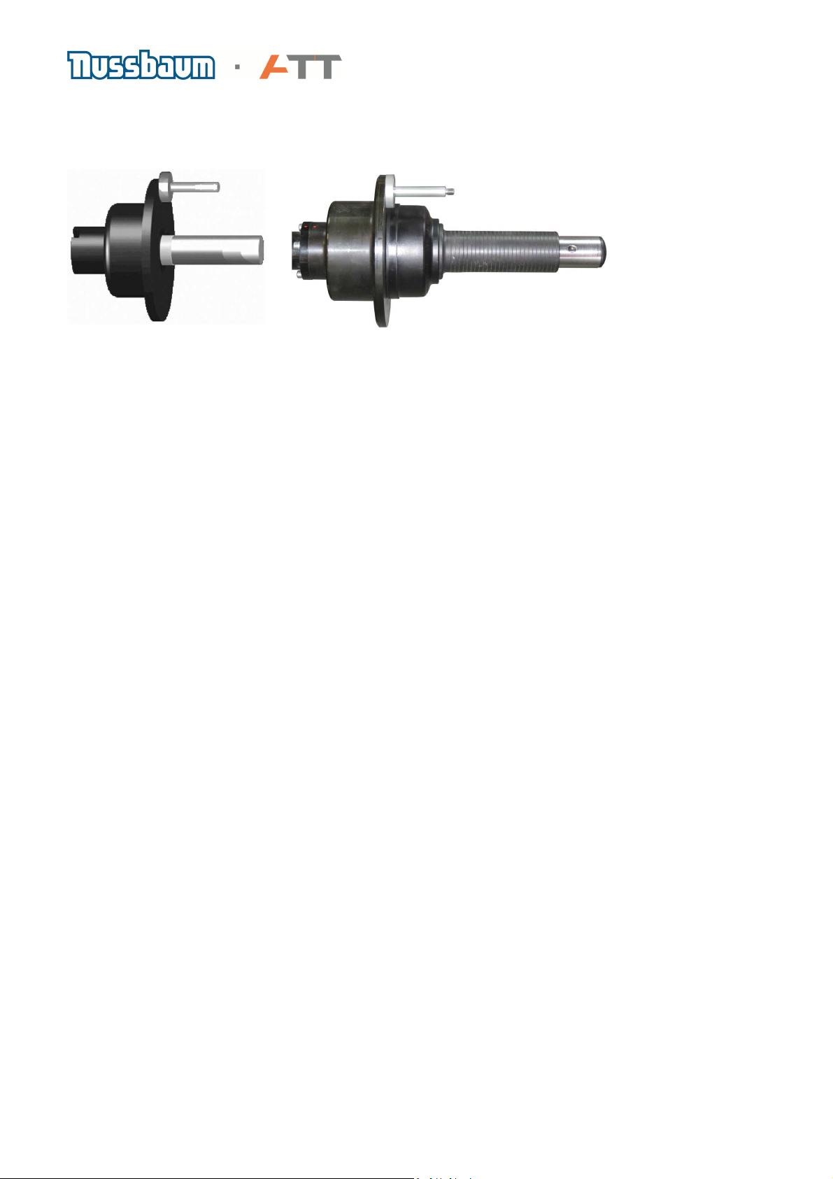
3. Measuring run
Run with calibration weight on the right side of the mid centering device
Machines with manual QuickSpan
clamping of the wheel
F 6 Autorun
If Autorun is active (ON) the balancing run is started when the wheel guard is closed. If Autorun is
not active (OFF) the balancing run needs to be started by pushing the START button when the
wheel guard is closed.
F 7 Suppression of minor imbalances / Round off
The suppression and rounding off of the balance results can be selected with this function
The suppression (lin) indicates below which value the imbalance is shown as „Zero“.
The round off (rnd) states in whwat steps the imbalance is displayed.
F 8 Wheel guard
SEC ON If the wheel guard is opened during the measuring run the wheel is stopped to an
immediate standstill
SEC OFF If the wheel guard is opened during the measuring run the motor is switched off and
the wheel runs free. This function is useful to view the run out of the wheel. As soon as the hood
is closed again the measurement run will start again from the beginning
--- The wheel guard switch is put out of operation, the balancing run can be started with the
wheel guard open
This function is only to be used for service purposes
Page 28 of 54
Page 29

F 9 Test function
With function F9 several ACTUAL values can be checked. This is helpful when a failure of the
machine has to be analyzed.
Routine:
Press function key to select the function menu. Use +/- keys to select the Function 9.
Press function key again to activate the function.
The following data can be retrieved in the order stated below. Via the „+“ or „-“ button you can
switch from one information to the other, the different data are paged through.
With reaching the last function value the program begins again with the first data (shaft position)
- Actual shaft position
This value can lie between 0 and 255 and changes with the rotation of the shaft.
- Actual distance of inner gauge arm
Is the PAX balancing program active (LED 19 PAX is light) the value is displayed in mm. The
reference is the edge of the cabinet and when the gauge arm is in home position it should be
50 +- 5. The maximum value should be 325 +- 5
- Actual diameter of inner gauge arm
Is the PAX balancing program active (LED 19 PAX is light) the value is displayed in mm
The reference is the edge of the cabinet and when the gauge arm is in home position it
should be 260 +- 5. The maximum value should be 650 +- 5
- Actual width
Is the PAX balancing program active (LED 19 PAX is light) the value is displayed in mm
The reference is the edge of the cabinet and when the gauge arm is in home position it
should be 556 +- 10.
Is there no width gauge present the value 950 is displayed
- Actual position of the hood
The display will show the actual status of the wheel guard switch (OPEN or CLOSE)
- Status of the brake
The display will show the actual status of the brake (OPEN or CLOSE). If the ALU button is
pressed the brake is activated (ON) or deactivated (OFF)
- Status of the QuickSpan
The display will show the actual status of the QuickSpan switch in the foot pedal (OPEN or
CLOSE)
- Temperature
The temperature is measured in a range of 200 to 700 (corresponds to -20°C to +70°C)
Temperature < -20° C, Outside measuring range
Temperature > 70° C, Outside measuring range
- Cal. = Temperature at which the machine was calibrated
Act. = Actual temperature in 1/10 °C
Page 29 of 54
Page 30
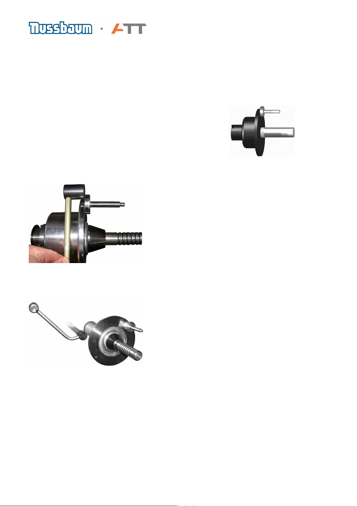
F 10 Calibration of the gauges
! It is important that the gauges are always placed in the home position after measurements as
this can result in inaccurate results.
! The brake should be released on all machines that have this function.
For the calibration of the gauges the calibration weight is
required. It has to be attached to the mid centering device as
shown in the left picture
Step 1 – POS 1 - Distance
Extend the inside gauge to the position 1 and hold it there until an audible signal is heard, which
means the measurement has been accepted
Step 2 – POS 2 - Diameter
Still in the extended position turn the gauge towards you into position 2 and hold until an audible
signal is heard, which means the measurement has been accepted
Place the inside gauge back in the home position and an audible signal should be heard
With machines without an outside gauge the calibration procedure is complete and the program
returns to normal mode.
Page 30 of 54
Page 31
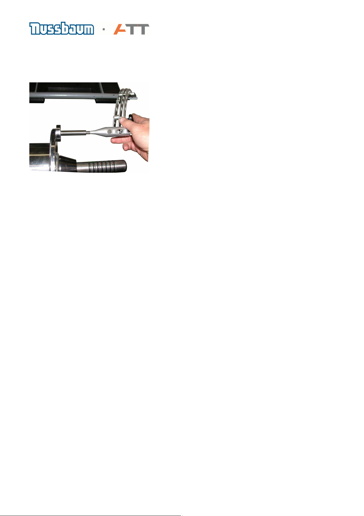
Step 3 – POS 3 – Width (only when an outside gauge arm is present)
Bring the tip of outside gauge to the tip of the “long” end of the calibration weight and hold it in this
position until an audible signal is heard, which means the measurement has been accepted.
Return the outside gauge into the home position and an audible signal is heard and the program
returns to normal mode
F 11 Counters
There are 3 counter values displayed that appear automatically one after the other with app. 10
seconds gap:
1. The first counter value shown is the total number of measurement runs since commissioning
of the machine. The counter value shown on the display should be multiplied by 10 to get
the actual value.
2. Number of measuring runs since last calibration.
3. Number of measuring runs since last power on of the machine.
After having displayed all counters the machine will change back automatically to normal mode
F 13 Setting of the brake
br --- Brake active. After the measuring run the wheel is stopped in the left correction plane
--- br Brake active. After the measuring run the wheel is stopped in the right correction plane
--- --- Brake disactivated
F 14 Setting of automatic cycle
Automatic cycle ON means:
- The wheel will be stopped in the 1st imbalance position and locked
- After having attached the weights the wheel will be moved automatically into the 2nd imbalance
position by pressing the STOP / POS button
Automatic cycle OFF means:
The wheel will be stopped in the 1st imbalance position and locked
- Does the operator want to move the wheel into the 2
nd
imbalance position he has to push the
STOP button in order to unlock the brake. In this case the wheel needs to be moved into the 2nd
position manually and locked there by pushing the STOP button
Page 31 of 54
Page 32
A
B
C
D
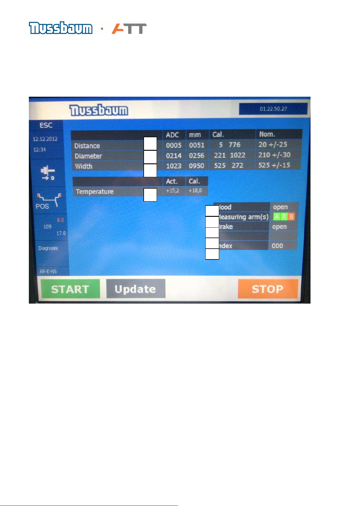
TOUCH PC BALANCERS
When the area with the software version is touched twice coming from the fist screen a service
screen will be displayed.
In this screen there is an overview over all the functions
A Actual distance of inner gauge arm
The reference is the edge of the cabinet and when the gauge arm is in home position it
should be 50 mm +- 10
B Actual diameter of inner gauge arm
The reference is the edge of the cabinet and when the gauge arm is in home position it
should be 260 mm +- 10
C Actual width
The reference is the edge of the cabinet and when the gauge arm is in home position it
should be 556 mm +- 10
D Temperature
The temperature is measured in a range of 200 to 700 (corresponds to -20°C to +70°C)
Temp < -20° C, Outside measuring range - Temp > 70° C, Outside measuring range
Cal. = Temperature at which the machine was calibrated
Act. = Actual temperature in 1/10 °C
Page 32 of 54
Page 33

E Actual position of the hood
The display will show the actual status of the wheel guard switch (OPEN or CLOSE)
F Indication if gauge arms are in the home position
GREEN = Gauge arm is located in home position
RED = Gauge arm is not in home position (also if gauge arm is not present or set out of
operation
G Status of the brake
The display will show the actual status of the brake (OPEN or CLOSE)
H Status of the QuickSpan
The display will show the actual status of the QuickSpan switch (OPEN or CLOSE)
K Actual shaft position
This value can lie between 0 and 255 and changes with the rotation of the shaft.
Page 33 of 54
Page 34
16. Mid centring device (NOT QuickSpan)
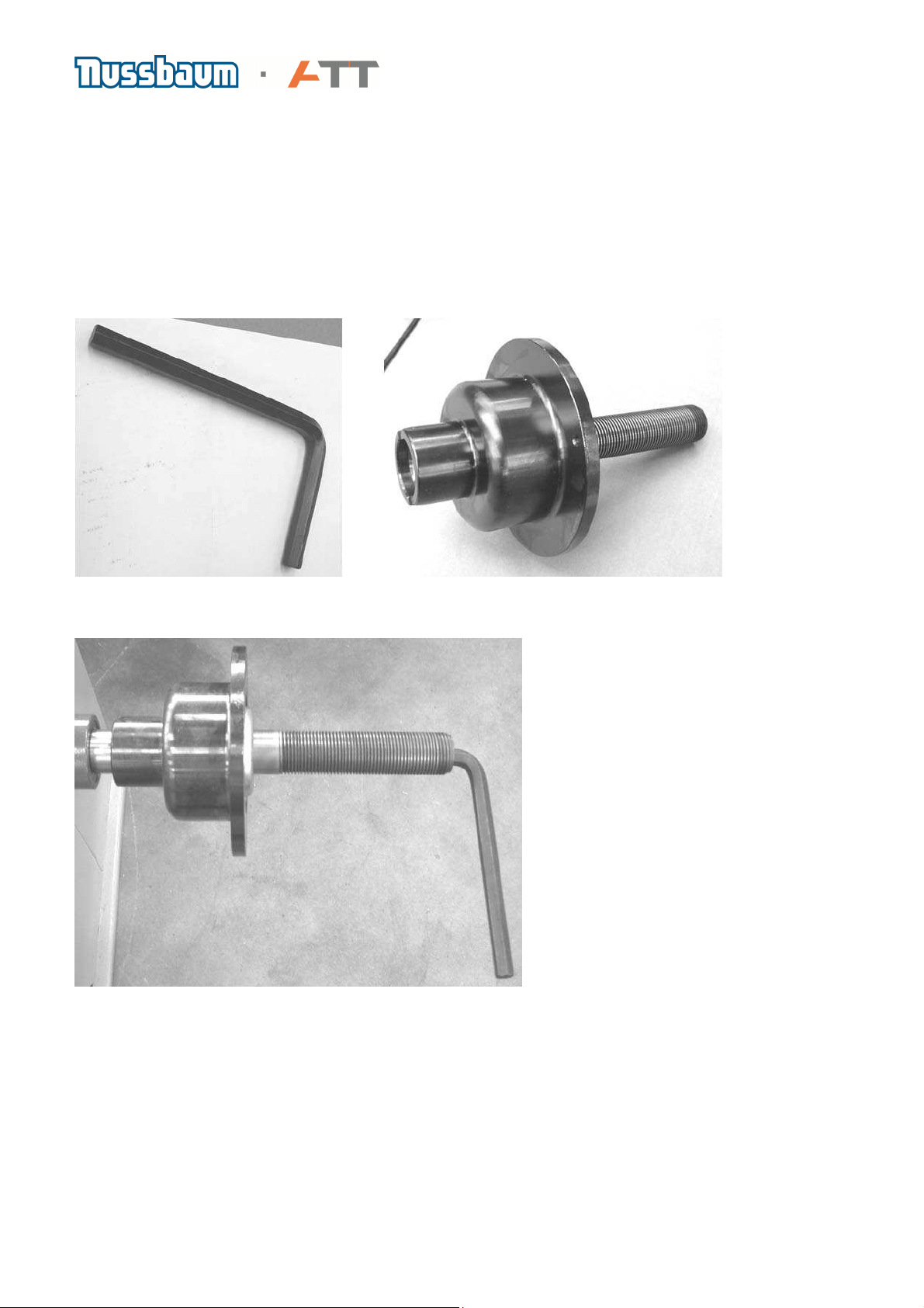
a) In order to change the clamping means, switch off the machine. At the centre and inside of the
threaded shaft there is a large securing bolt, which requires an Allen key, which comes with the
standard scope of delivery (photo below) to loosen. Then take a rubber hammer and holding the
shaft in one hand, slightly tap on the inside of the clamping means until it loosens from its
mounting cone on the main shaft of the balance machine.
The left photo shows the Allen key used to loosen the clamping means on the right. The photo
below shows the process of removing the clamping means.
b) Before replacing the clamping means, clean the main shaft cone with a clean cloth. Before
tightening the centre bolt, make sure that the position of threaded hole for the calibration weight
aligns up in line with the red point on the main shaft.
c) Technical data
Diameter of the shaft is 40mm with a cone centre hole of SK40
Diameter of the trapezoidal screw thread TR40x3 is 40mm
Page 34 of 54
Page 35
17. QuickSpan
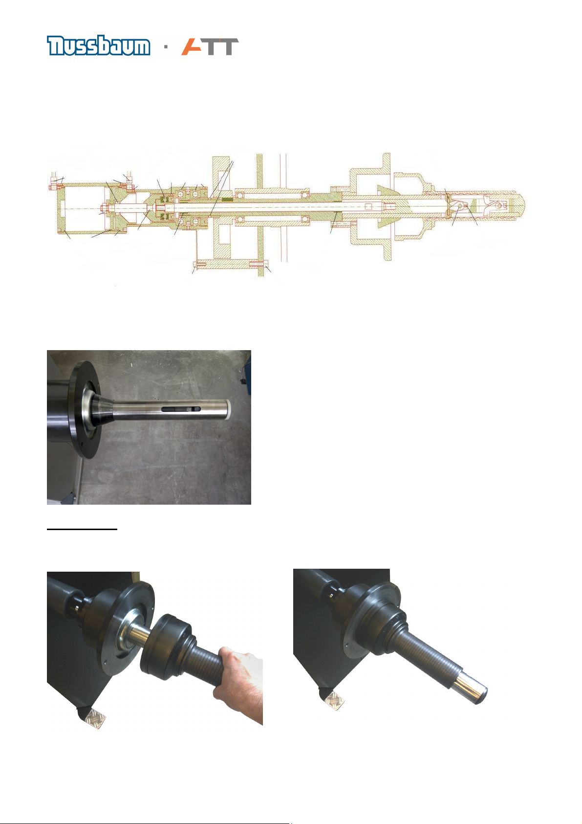
Principle
With the QuickSpan the wheel is clamped pneumatically upon foot pedal operation. The shaft
diameter is 40 mm and all clamping accessories that can be used with the wheel balancers with
manual clamping can also be used with the QuickSpan
IMPORTANT: For calibration of the QuickSpan machines as well as the zero run the clamping
sleeve and the clamping hood for steel rims as shown in the pictures below. NO cone shall be
used
For more information on calibration and zero run please see the instruction manual
Page 35 of 54
Page 36

18. Foot pedal (QuickSpan)
a) The foot pedal is used to clamp the wheel to the main shaft and is NOT designed to be used as
a brake to hold the main shaft.
b) The pedal is part of a metal plate, which is constructed with a small bolt attached to relieve the
pressure of someone applying full force to the pedal and damaging it after a while. If this screw is
set in the wrong position, it can lead to the breakdown of the mechanical switches or that the
switch point cannot be reached due to the brakes being applied too early. Loosen the securing nut
and turn the adjuster in the desired position. Tighten the securing screw afterwards.
c) The foot pedal switch works as an opener, meaning the following:
- If the foot pedal is not operated at all the switch is closed
- If the foot pedal is pushed and hold in the push position the switch opens
The measurement of the resistance between the contacts 3 and 4 on the cable from the foot
pedal switch brings the following results
- Foot pedal not operated Connection between contacts 3 and 4 (resistance = 0)
- Foot pedal operated and hold No connection between contacts 3 and 4 (high resistance)
Please note that the software does check the foot pedal switch during power on and based on the
status of the switch does activate the QuickSpan function or not. This means that, if the foot pedal
is pushed during “power on” of the machine it can happen that the software does recognize an
open switch and puts the QuickSpan out of operation.
It is important to leave the machine untouched during the power on process, especially on a
machine with Touch PC as the power on takes some time
If there is not any difference in behavior of the switch when operating the pedal or leave it this can
have 2 reasons:
- The foot pedal switch is defect
- The mechanical connection between the foot pedal itself and the switch does not allow to
operate the switch
Page 36 of 54
Page 37
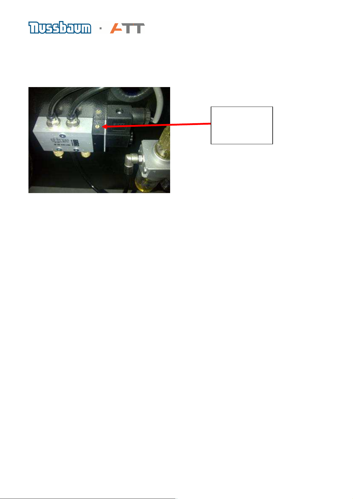
19. Maintenance unit (QuickSpan)
The photo below shows the air pressure control unit for the quick span machines.
Screw to operate
the QuickSpan
valve manually for
testing purposes
The maintenance unit is equipped with a water separator, an oiler and a pressure gauge. The
pressure is reduced to 6 bar and must not be adjusted to a higher value.
The oiler needs to be checked on a regular basis in order to make sure that there is always
enough oil present.
Running the QuickSpan without oil can lead to a malfunction of the complete system
The operating pressure should be between 8 – 10 bars to enable a wheel to be clamped correctly.
The air pressure magnet valve is controlled by the motor control board. (See chapter on motor
control board).
In order to check that the valve is working fine manually it can be operated by turning the screw
as indicated above.
The solenoid valve of the maintenance unit is operated with 32 Vac
Page 37 of 54
Page 38
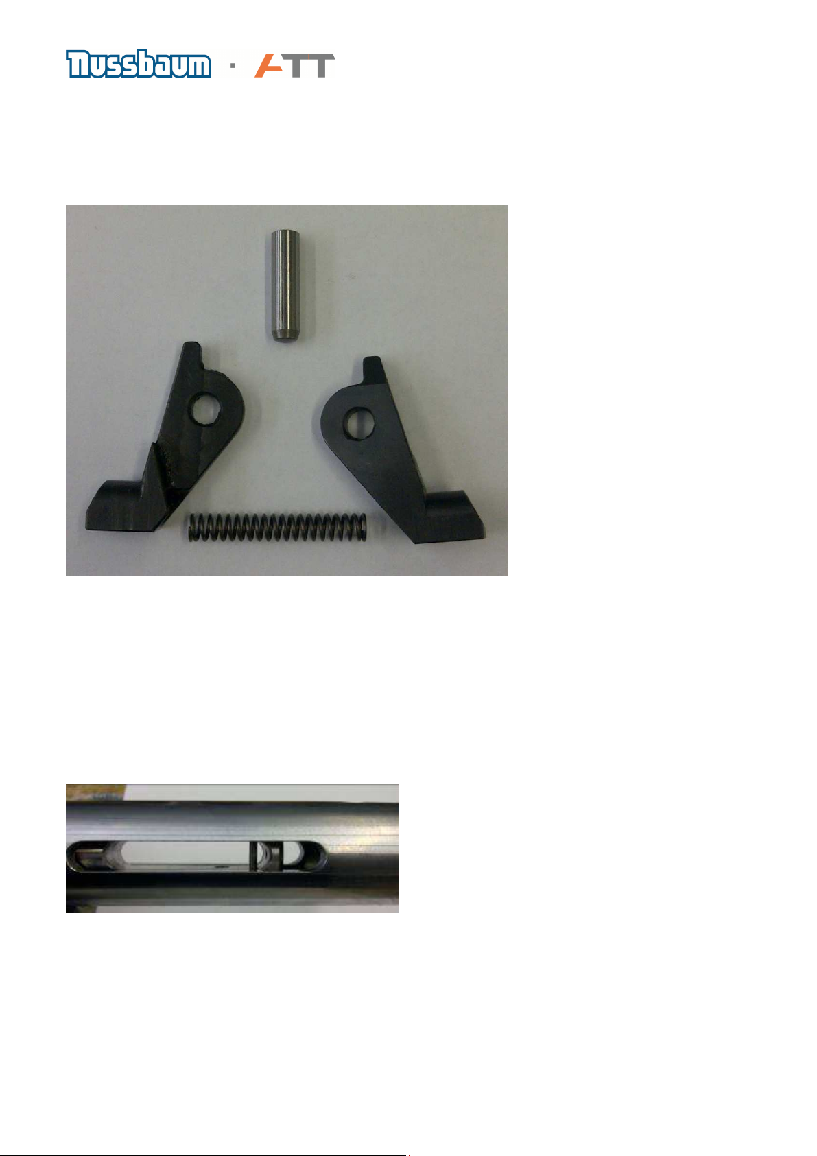
20. Repair Instructions for clamping fingers (QuickSpan)
REQUIRED PARTS
1
2
Repair kit 1987009W8LA
1. Splint
2. 2 x Clamping fingers
3. Spring
2
3
Position the pull shaft in the 40 mm shaft so that
the clamping fingers and the spring can be
mounted
Page 38 of 54
Page 39
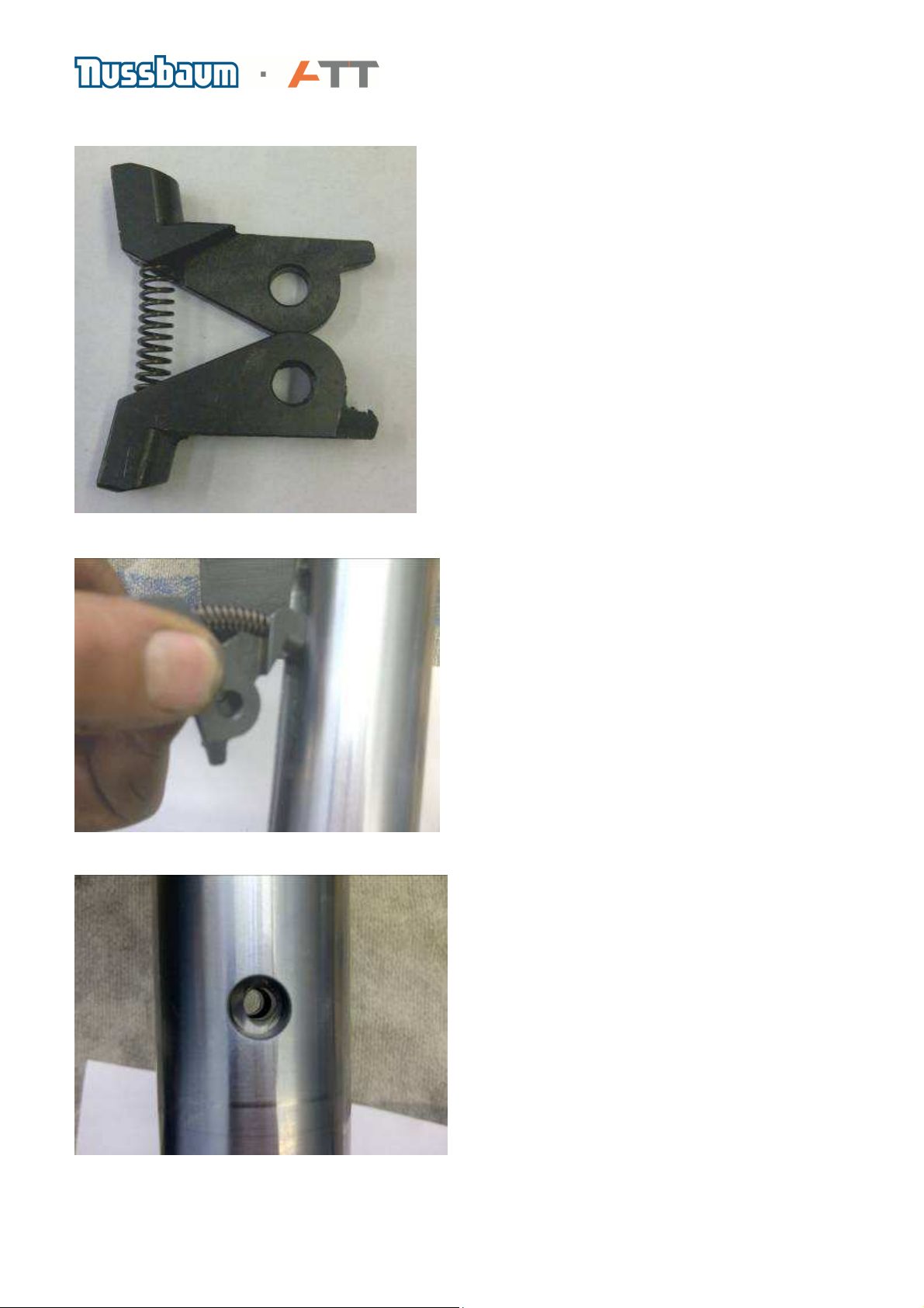
Assemble and grease well the two clamping finger and
the spring
Insert the he clamping fingers and the spring into
the pull shaft
Position the clamping fingers and the spring such
that the splint can be fitted
Page 39 of 54
Page 40
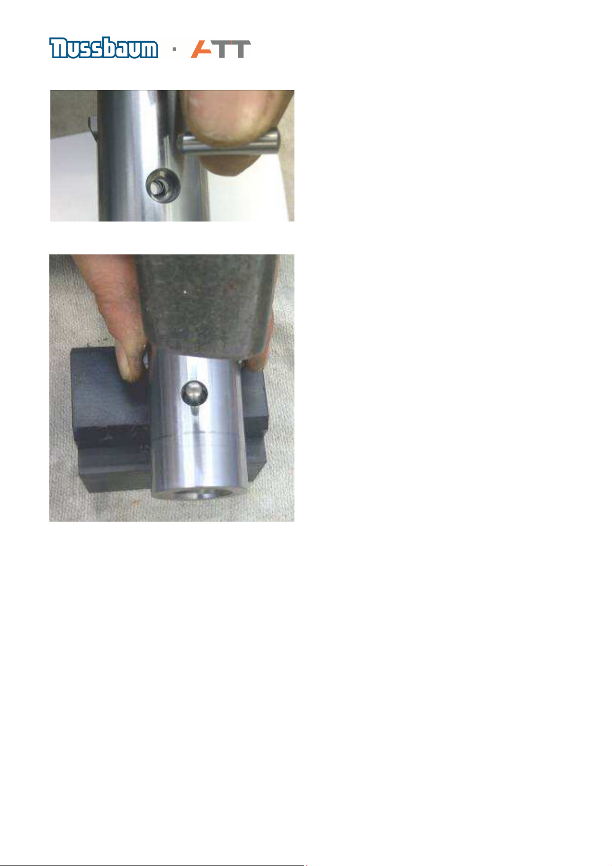
Mount the splint
While the pin is mounted with a hammer, always
make sure that the two fingers do move well
Once the pin has been installed check that the pull shaft can be easily moved back and forth inside
the 40 mm shaft
!!!! Perform a calibration and a zero run !!!!
Page 40 of 54
Page 41
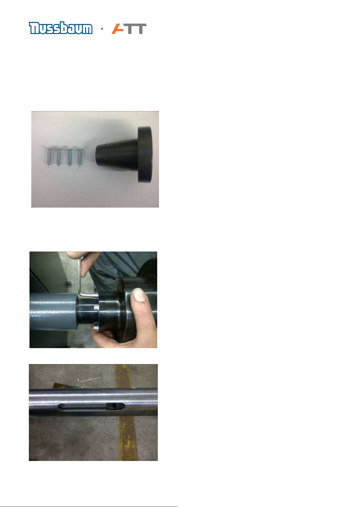
21. Using UNI-LUG and Motorcycle adaptor on QuickSpan
1987009W8JA
Adapter kit to mount motorcycle adaptor and Universal flange to QuickSpan wheel balancers
1 adaptor
4 tapered screws M 6 x 25 to pre centre the cone
adaptor and the flange
MOUNTING INSTRUCTIONS
Remove the 4 screws holding the flange
When all screws have been removed open the
QuickSpan via the foot pedal
Page 41 of 54
Page 42
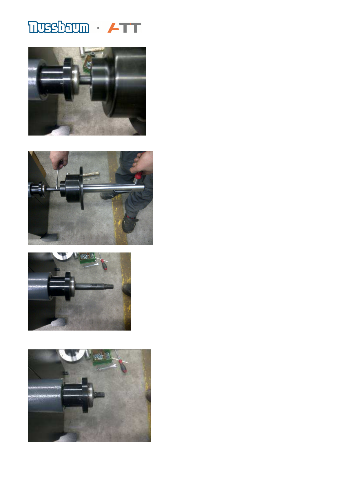
Move the flange away from the cabinet until the pull rod is
seen
Unscrew the flange using the 13mm wrench and a
screwdriver as shown
Move the pull rod via the foot pedal to the back (clamp
QuickSpan)
Page 42 of 54
Page 43
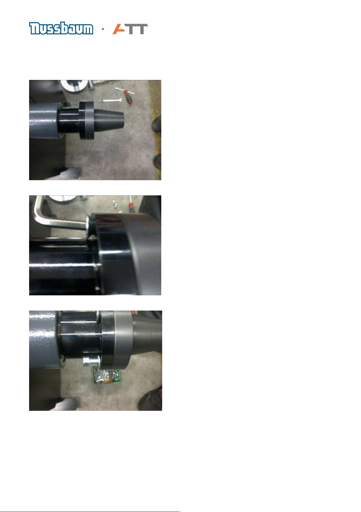
DISCONNECT THE AIR SUPPLY TO PREVENT THE QUICKSPAN TO UNCLAMP UNEXPECTLY
Which may result in an internal damage
Attach the adapter to the balancing unit
Pre centre the adapter using the delivered tapered
screws
Replace the tapered screws with the „original“ helical
screws and tighten them crosswise
After having tightened all 4 „original“ helical screws put the motorcycle adaptor or the
universal adaptor on the cone and tighten it with the screw (Shaft of the motorcycle adaptor /
16mm screw on universal adaptor)
Perform a zero run
Page 43 of 54
(refer to instruction manual for more information)
Page 44
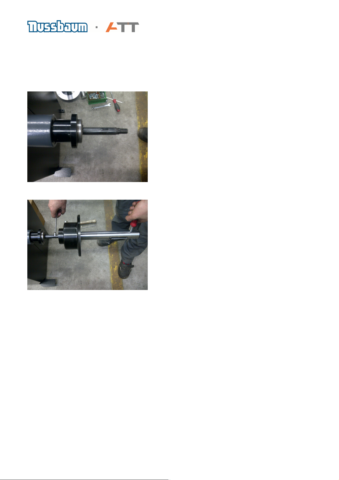
Retrofit mid centring device
Remove the 4 screws and demount the adaptor from the balancing unit
Connect the machine to the air supply and move the
pull rod out by using the foot pedal
Place the flange on the pull rod and tighten it using a 13
mm wrench and a screwdriver
Page 44 of 54
Page 45
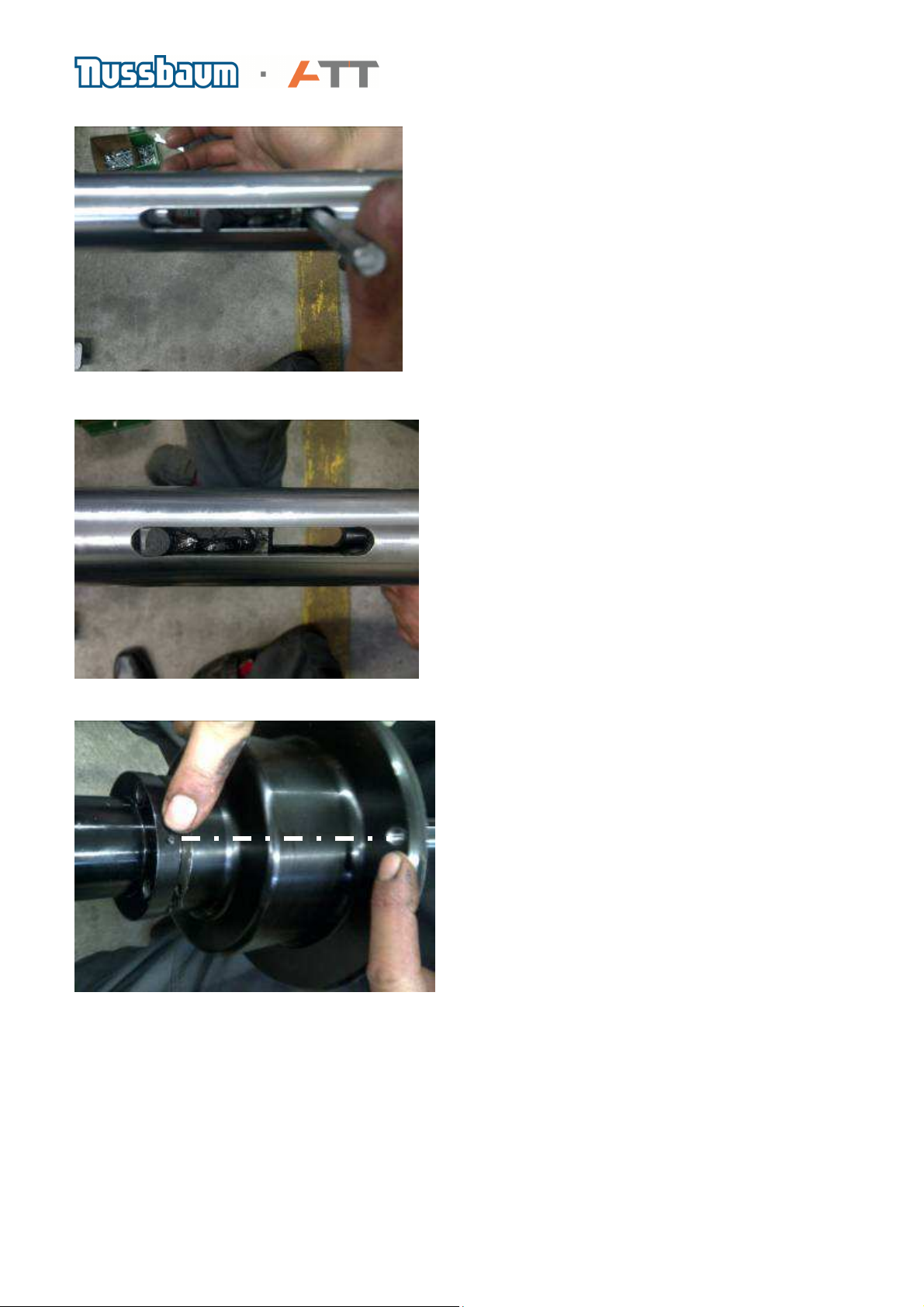
Push the flange back so that the pull shaft is located in
the middle position (see picture below)
Position the flange on the balancing unit in a way
that the point on the balancing and the calibration
thread on the flange are in line
Page 45 of 54
Page 46
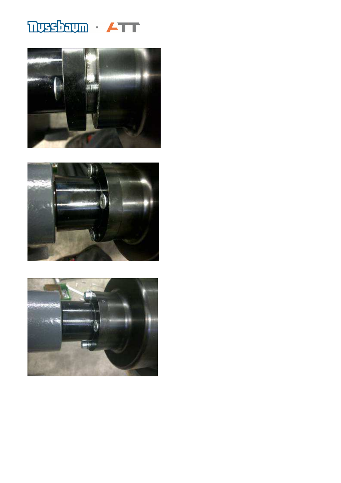
Pre centre the flange on the balancing unit using the
4 tapered screws
Replace the tapered screws with the „original“ helical
screws and tighten them crosswise
Perform a zero run
(refer to instruction manual for more information)
Page 46 of 54
Page 47
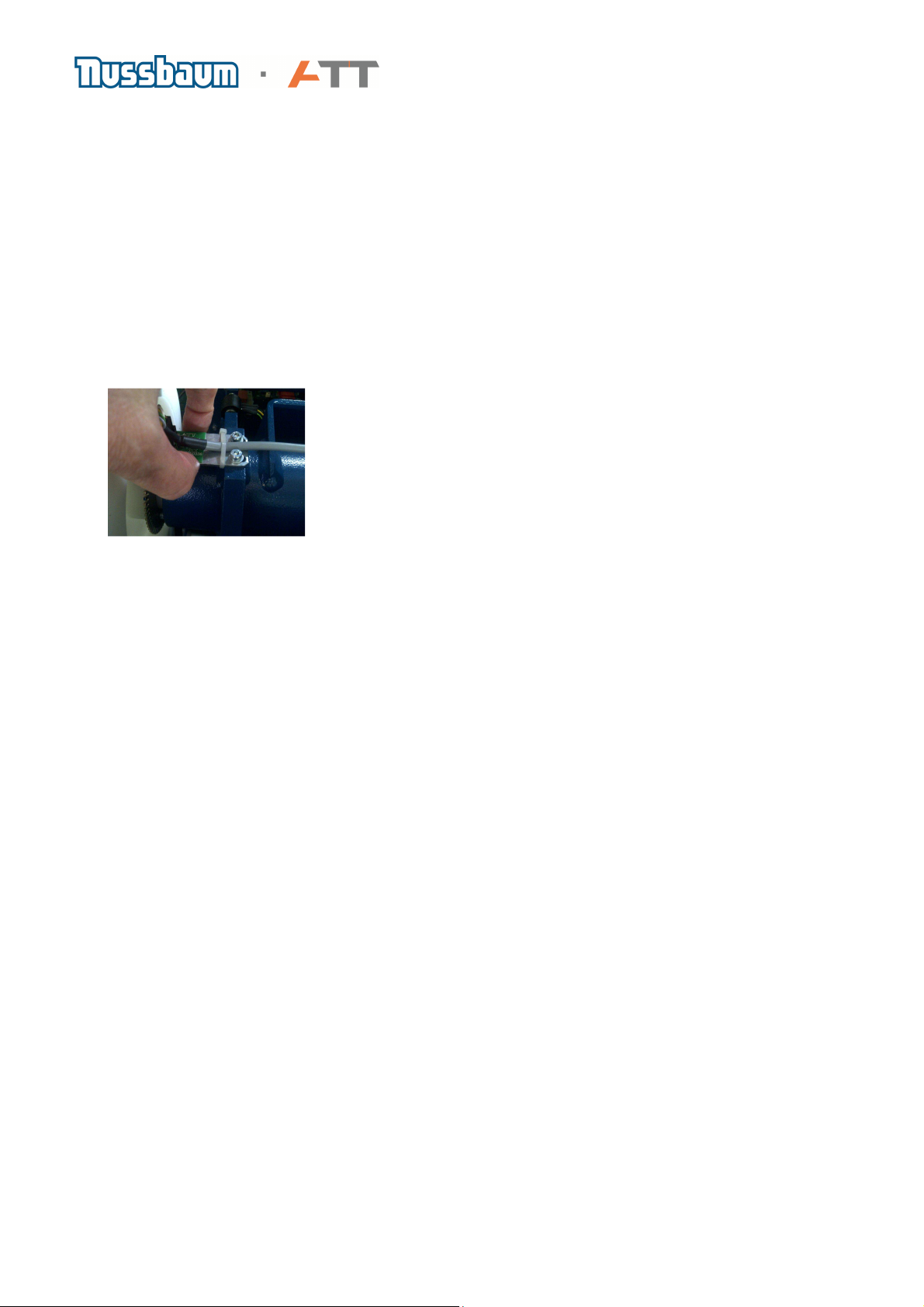
22. Trouble shooting and problem solving
The following lists show the possible problems that might occur and some solutions how to solve
them. This list can be expanded and it is advised to check frequently on our home page under
Service/ frequently asked questions. Go through the remedies one by one until the problem is
solved. If the problem cannot be solved after trying all these possibilities, please report to a
Nussbaum technician.
"E7 Ind", index error
Problem in recognizing the optical encoder board
Remedy:
- Push the board slightly down or lift it slightly up in order to achieve the right distance
- Check that all cables are well connected to the connectors
- Check if the opto encoder is recognized with Service function F 9
"E10 dir",direction error
- The opto encoder recognizes that the shaft is turning in the wrong direction
"E11 Mot"Drive problem (brake, opto encoder, belt)
Remedy:
- Push the board slightly down or lift it slightly up in order to achieve the right distance
(see E7 Ind)
- Check that all cables are well connected to the connectors
- Check if the opto encoder with Service function F 9
- Check if motor is defect
- Check if belt is tight enough
Problem
On switching on the machine, the display does not illuminate.
Remedy
Check the mains power supply. It should be between 230V +/- 10%, and 110V +/-10% depending
on model. If the mains supply has a tendency to fluctuate, it is advised to protect the machine
electronics from damage by using a voltage regulator.
− Check the main on/off switch to make sure that it is not mal functioning. If damaged, replace.
− Check the main fuse X1-F1 on the terminal strip. Change if necessary.
− Check fuses F1-F4 on the motor control board. Replace if necessary
− Check the voltage coming from J6 on the motor control board. If no voltage shown, change board.
− Check voltage from J9 of the basic board. If voltage is wrong, check the connection leads.
− Check the jumper J13 on the basic board. They should be open for normal operation and closed
for flashing new software. Replace as to requirements.
− Check the Basic board on another machine if possible.
Page 47 of 54
Page 48

Problem
Fluctuating results after repetitive balance runs
Remedy
Make sure that the correct cone has been used for the wheel and that the clamp is secure and tight on
the clamping means.
− Check that the machine is on level hard ground. If necessary bolt machine to the ground. Never
use machine when it is bolted on a wooden pallet.
− Check the software version. Update if it is lower than 1.6. Software can be downloaded from our
home page.
− Check Piezo sensors - Make sure they are tightened to exactly 2 Nm and that the securing nut is
tight. Check the cables and connectors that they are secure and in good condition.
− Check the bearing play in the main shaft. IF there is too much play, make sure that the belt pulley
securing bolt is tightened to 10Nm securing with Loctite. If the bearing play cannot be relieved,
change the mains haft assembly.
− Make sure that the clamping means is clean and tight on the main shaft. Check the tightness of
the securing bolt and clean clamping means completely with a clean dry cloth.
Page 48 of 54
Page 49

Problem
0 – 0 Cannot be achieved after correcting unbalance with weights
Remedy
− The wrong program might have been chosen- the program is not suitable for the required
weight position
− Wheel data not correct – Check that the inputted wheel data corresponds exactly to that of
the wheel and the program.
− Zero run and/or calibration run have not been done correctly. Carry out again according to
instructions in the user manual.
− Clamping means is not correctly tightened. Check and clean all parts.
− Position of the clamping means on the main shaft is incorrect. The threaded hole for the
calibration weight should be in line with the red marking on the main shaft axis. (see
installation instructions)
− Check the position of the clamping means. LED machines, select F9 and rotate the shaft until
P0 is reached. The threaded hole in the clamping means should be in 12 0 clock position. If
not, reposition.
− Check if the opto encoder is mounted and positioned correctly. Opto encoder LED 1 and 3
and 2 should light and extinguish. The point 0 is shown when LED 3 extinguishes and stays
out.
− Check the free running of the main shaft. By tightening the bolt on the end of the shaft the
main shaft can be tightened.
− Make sure the 4 securing bolts for the main shaft assembly are secure. Tighten if necessary.
− Check to see that there is no contact between the axis of the main shaft assembly and the
cabinet body.
− Check to make sure the Piezo sensors are fitted correctly. Too loose and they give false
readings, too tight they become damaged. Sensors should be fitted according to service
instructions. Every time work has been carried out with the sensors, a new calibration should
be carried out.
Page 49 of 54
Page 50

Problem
Inside arm gives incorrect readings for the distance and diameter of the wheel
Remedy
− The chain for distance gauge is not fitted correctly to the chain pulley. Loosen the pulley
mechanism and replace according to the service instructions
− Connection J8 is not in contact with the basic board. Check connections and leads.
− Inside arm calibration is incorrect. Select F10 and carry out the routine according to user
handbook.
− Check the resistance of the potentiometer with a multi meter. It should read about 10k ohms.
If it is less, change the potentiometer.
− Check fuses F4 and F5 on the motor control board. Change if necessary. (160mAT).
Problem
No reaction after pressing any buttons on the monitor machines in conjunction with the user
manual
Remedy
− Check the serial cable connection from the Touch PC to the basic balancing board
− Make sure that the basic board and the Touch PC are started at the same time, i.e. after
switching the machine on.
If the Touch PC is switched off and on again without switching off and on the complete
machine there is no synchronization between the basic balancing board and the Touch PC
Problem
Machine does not start in automatic mode after closing the wheel guard.
Remedy
− Check the functions F6, or under the menu settings in the main menu. If required, select ON
position.
− Check the wheel guard micro switch is functioning properly. Make sure it is not damaged and
that the cam is sitting on the shaft in the correct position.
− Check the connection leads and connectors. The leads should not be damaged and all
connections secure. If necessary exchange leads.
Problem
Quick span-clamping means does not work
Remedy
− Check the air pressure at the maintenance unit. The air pressure for the cylinder is limited to 6
bar.
− Make sure the foot pedal is working. Check that the mechanical function together with the
adjustment bolt is correct.
− Check the connection leads for mechanical damage and all connections for security. If
necessary exchange.
Page 50 of 54
Page 51
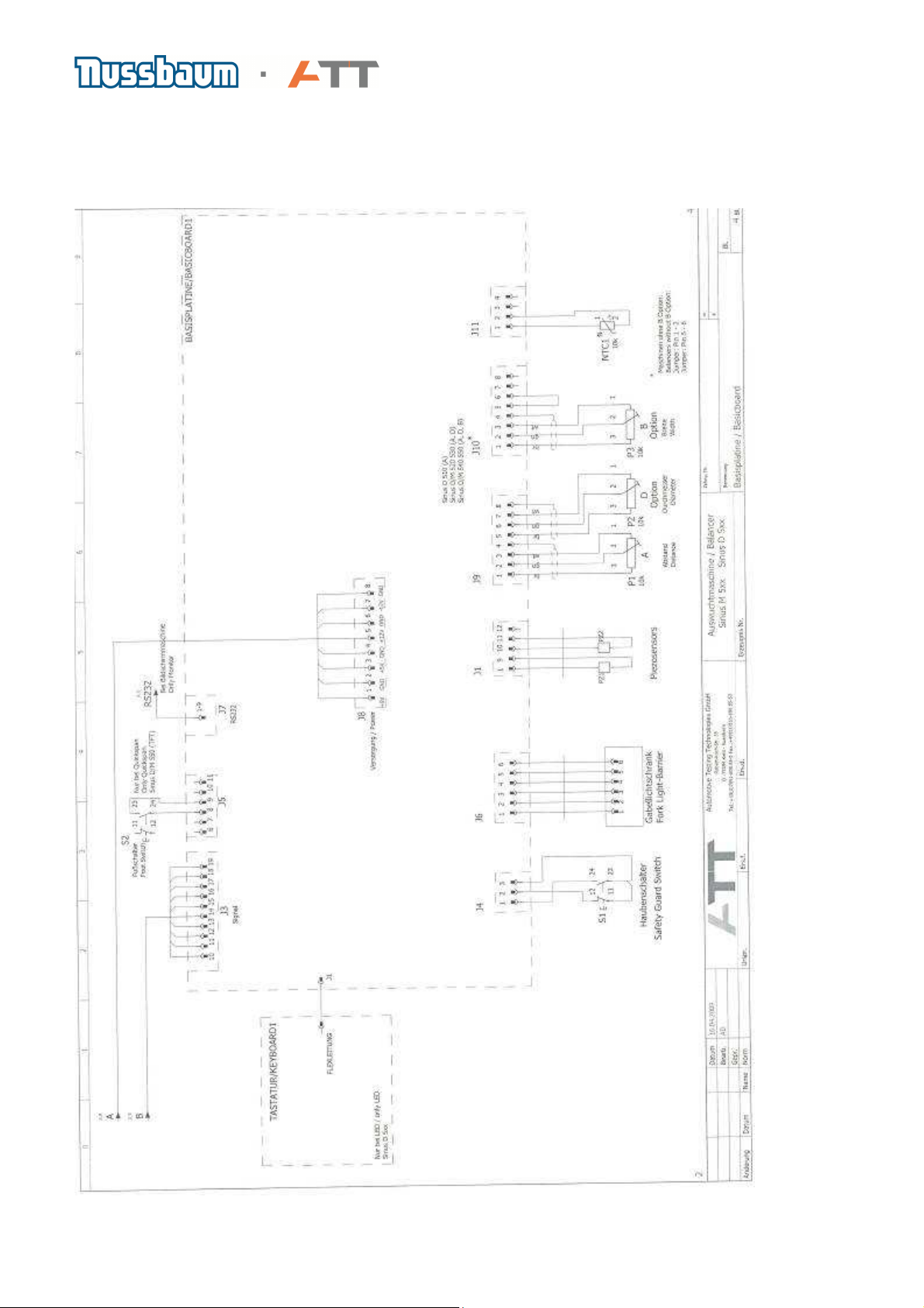
23. Electrical schematic layout
Basic Board
Page 51 of 54
Page 52
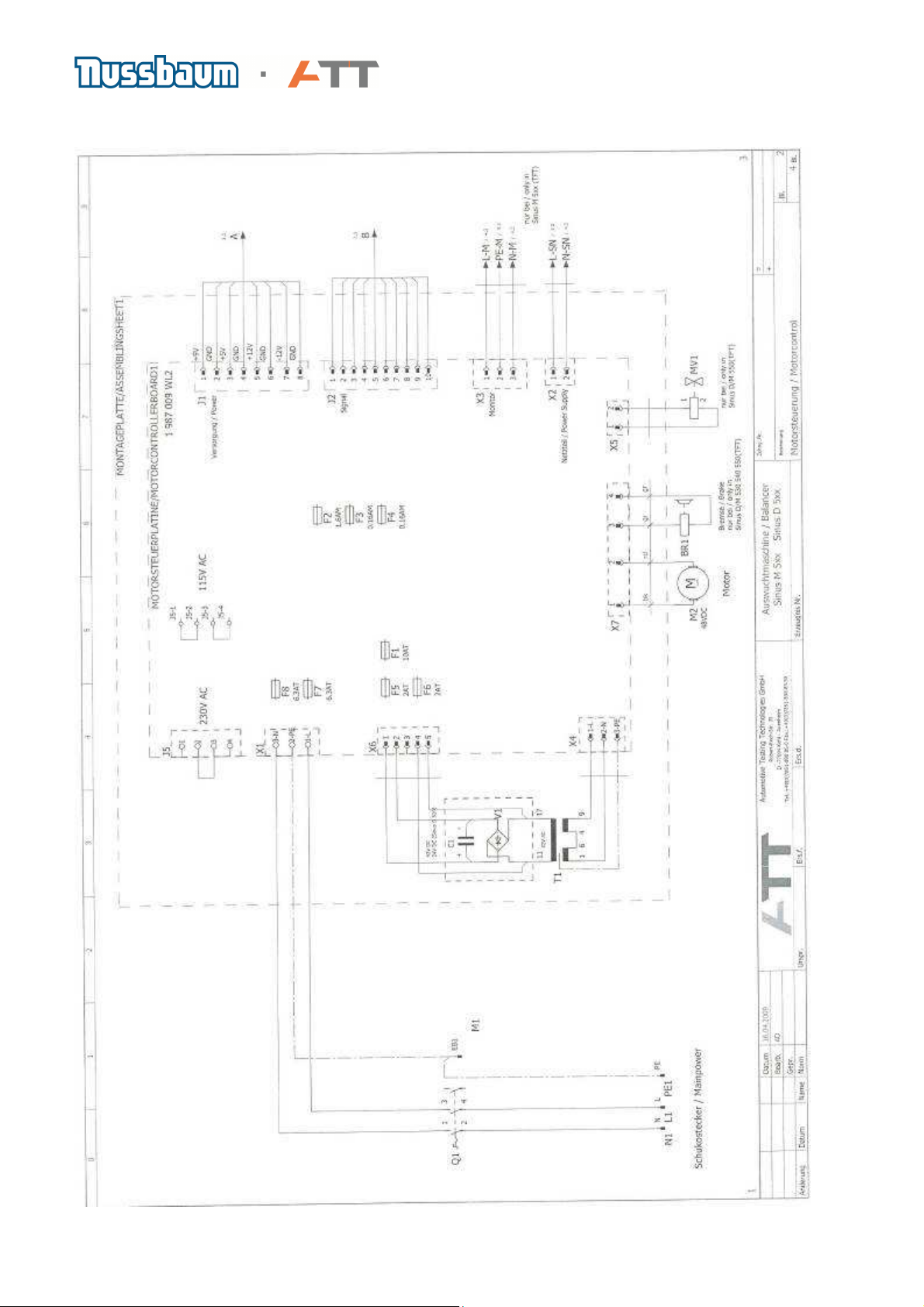
Motor control board
F4 – - 12V
F3 – + 12V
F2 – 5V / 12V
Page 52 of 54
Page 53
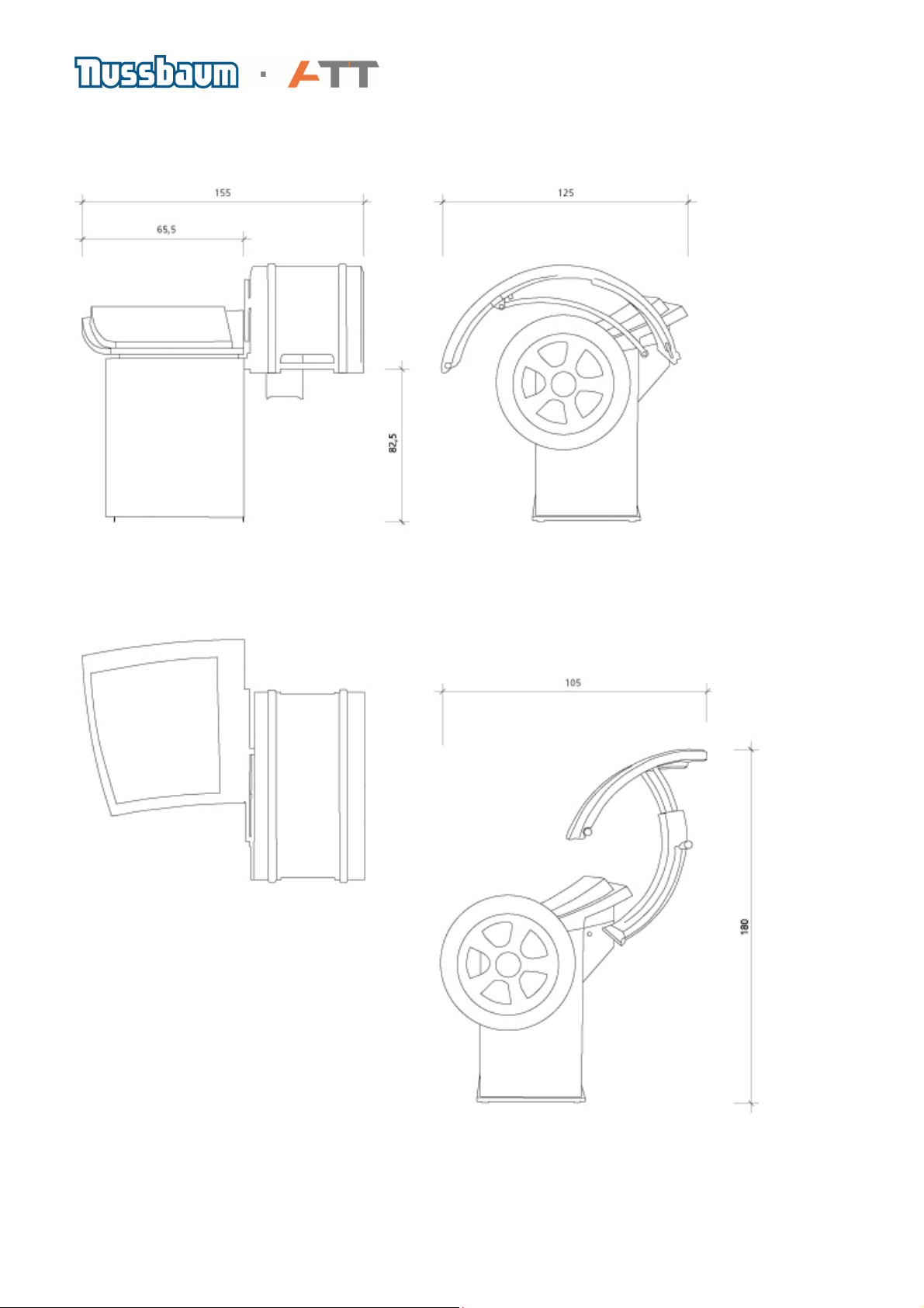
24. Dimensions
Page 53 of 54
Page 54
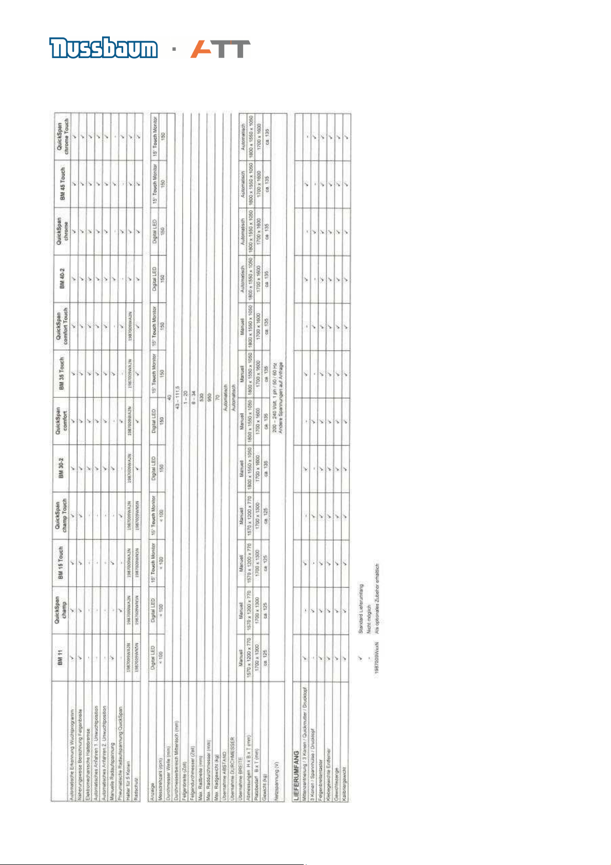
25. Technical data
Page 54 of 54
 Loading...