

Page 1
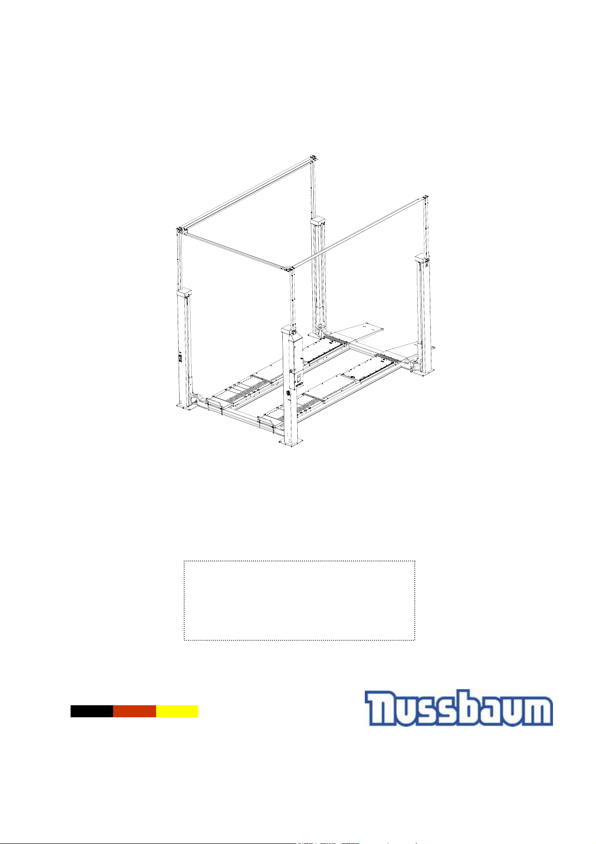
4.50 SL (BMW)
Automotive Lift date: 04/2012
Manual Date: 01.04.2012
Operating Instruction and Documentation
Serial-number:............................................
Retailer address / phone
Made in Germany
Otto Nußbaum GmbH & Co.KG ● Korker Straße 24 ● D-77694 Kehl-Bodersweier
E-mail: [email protected] ●
Tel: +49(0)7853/8990 ● Fax: +49(0)7853/8787
http://www.nussbaum-lifts.de
Original Documentation
Page 2
Operating Instruction and Documentation
4.50 SL
Content
Foreword ....................................................................................................................3
Record of installation ..................................................................................................5
Record of handing over ..............................................................................................6
1.General Information .................................................................................................7
1.1 Installation and service checks of the automotive lift ............................................7
1.2 Warning Symbols .................................................................................................7
2. Master document of the automotive lift.................................................................8
2.1 Lift–manufacturer..................................................................................................8
2.2 Application ............................................................................................................8
2.3 Changes at the construction.................................................................................8
2.4 Displacement of the automotive-lift.......................................................................8
2.5 Declaration of conformity......................................................................................9
3. Technical Information ...........................................................................................10
3.1 Technical ratings ................................................................................................11
3.2 Safety device ......................................................................................................11
3.3 Data sheet ..........................................................................................................12
3.4 Foundation diagram drawing ..............................................................................13
3.5 Electrical diagram drawing..................................................................................14
4. Safety regulations .................................................................................................38
5. Operating instructions..........................................................................................39
5.1 Lifting the vehicle................................................................................................39
5.2 Synchronism of the automotive lift......................................................................39
5.3 Lowering the vehicle...........................................................................................40
6. Troubleshooting ....................................................................................................40
6.1 Emergency lowering ...........................................................................................41
6.2 Driving onto an obstacle .....................................................................................42
6.3 Function of safety device....................................................................................42
6.4 Manually equalisation of the carriage .................................................................42
6.5 Driving to the Reference point ............................................................................43
7. Inspection and Maintenance.................................................................................44
7.1 Maintenance plan of the lift.................................................................................44
7.2 How often must the lift be cleaned?....................................................................46
7.3 Adjust the Polylex-belt ........................................................................................47
7.4 Examine the carrying nut system........................................................................48
7.5 Examine of the stability of the automotive lift......................................................49
8. Installation and Initiation ......................................................................................49
8.1 Regulations.........................................................................................................49
8.1.1 Erection and doweling of the lift....................................................................50
8.2 Initiation ..............................................................................................................51
8.3 Change of lift location .........................................................................................51
8.4 Key in the reference point with the keyboard......................................................52
9. Security check.......................................................................................................54
First security check before installation......................................................................58
Regular security check and maintenance.................................................................59
Regular security check and maintenance.................................................................60
Extraordinary security check.....................................................................................66
- 2 -
Page 3
Operating Instruction and Documentation
4.50 SL
Foreword
Nußbaum lifting systems are the result of over 25 years experience in the automotive lifting industry.
The high quality and the superior concept ensure reliability, a long lift lifetime and above all and
economic business solution.
To avoid unnecessary damage, injury or even death, read the operating instructions with care and
observe the contents.
Nußbaum lifts is not responsible for incidents involving the use of Nußbaum lifting systems for
applications other than those for which they were designed.
The Otto Nußbaum GmbH & Co. KG is not liable for any resulting damages. The user
carries the risk alone.
Obligations of the user:
- To observe and adhere to the operating instructions.
- To follow the recommended inspection and maintenance procedures and carry out the
prescribed tests.
- The operating instructions must be observed by all persons working with or around the lift.
- Above all chapter 4 “Safety Regulations“ is very important and must be closely adhered to.
- In addition to the safety regulations stated in the operating instructions manual, the appropriate
safety regulations and the operating procedures of the place of operation must also be
considered.
Obligations of the operator:
The operator is obliged to allow only those persons complying to the following requirements to work
with or around the unit.
- Persons being familiar with the basic regulations concerning labour safety and accident
prevention and being trained to operate the particular unit.
- Persons having read and understood the chapter concerning safety and warning symbols.
- Persons using the lift are required to confirm that they have read and understood the chapter on
safety and warning symbols by signing the appropriate form.
Dangers when operating the lift:
Nußbaum-Lifts are designed and built according to technical standards and the approved
regulations for technical safety. The use of Nußbaum lifts for purposes other than those for which
they were designed, may result in injury or even death.
The lift must only be operated :
- For its appropriate use
- In faultless condition concerning technical security.
- 3 -
Page 4
Operating Instruction and Documentation
4.50 SL
Organisational Requirements
- The instructions for use are to be kept at the place of operation being easily accessible
at any time.
- In addition to the instructions for use, rules pertaining to other regulations i.e. accident
prevention and environmental rules are to be observed and adhered to.
- The owner of the Nußbaum lifting system must ensure that operators and persons working with
or around the lift occasionally conduct “refresher” courses to ensure that the appropriate
operating procedures and safety precautions are known.
- Personal Protective Equipment (PPE) must be used according to the appropriate regulations.
- All safety- and danger signs on and around the lift are to be observed and followed!
- Spare parts must comply with the technical requirements specified by the manufacturer.
This is only warranted with original parts.
- Observe and adhere to the specified time intervals between tests and inspections.
Maintenance works, repairing faults
- Adjustments, maintenance, and inspections, are to be followed according to the time intervals
specified. Details regarding the exchange of parts and components as mentioned in the
operating instructions are to be adhered to.
These works must only be carried out by expert personal.
- After maintenance- and repair works loose screws, nuts and bolts must always be firmly
tightened!
Guarantee and liability
- Our “General conditions of selling and delivering” are in force.
There will be no guarantee or liability for incidents involving injuries or death or damage to
equipment if these incidents are the result of one or more of the following reasons.
- Inappropriate use of the lift
- Inappropriate installation, initiation, operation and maintenance of the lift.
- Use of the lift while one or several security devices do not work, do not work correctly or are not
installed correctly.
- Failure to follow the regulations of the operating instructions regarding transport, storage,
installation, initiation, operation and maintenance of the lift.
- Unauthorized changes to the structure of the lift without first asking the producer.
- Unauthorized changes of adjustments of important components of the lift (e.g. driving elements,
power rating, motor speed, etc)
- Wrong or incorrect maintenance practice.
- Catastrophes, acts of God or external reasons.
- 4 -
Page 5
Operating Instruction and Documentation
4.50 SL
After completely filling out this sheet including signatures, copy and return the
original to the manufacturer. The copy must remain in the manual.
Otto Nußbaum GmbH & Co. KG
Korker Straße 24
D-77694 Kehl-Bodersweier
Record of installation
The automotive lift with the
serial number:............................................ was installed on:...............................................
at the firm:................................................. at:.....................................................................
The initial safety check was carried out and the lift was started.
The installation was carried out by the operating authority/competent (please delete as applicable).
The initial safety check was carried out by a competent person before the initial operation.
The operating authority confirms the correct installation of the automotive lift, the competent person
confirms the correct initial operation.
Used Dowels(*):________________________________(Type/Name)
Minimum anchorage depth (*) kept: _________________mm F ok
Starting torque (*) kept: __________________________NM F ok
............................................ ..................................................... ............................................
date name of the operating authority signature of the operating authority
............................................ ..................................................... ............................................
date name of the competent person signature of the competent person
Your customer service:.....................................................................................................(stamp)
(*) see supplement of the dowel manufacturers
- 5 -
Page 6
Operating Instruction and Documentation
4.50 SL
Automotive Lift date: 04/2012 / Manual date: 01.04.2012
Record of handing over
The automotive lift with the
serial number:............................................ was installed on:...............................................
at the firm:................................................. at:.....................................................................
the safety was checked and the lift was started.
The persons below were introduced after the installation of the automotive lift. The introduction
was carried out by either the erector from the lift-manufacturer or from a franchised dealer
(competent person).
............................................ ..................................................... ............................................
date name signature
............................................ ..................................................... ............................................
date name signature
............................................ ..................................................... ............................................
date name signature
............................................ ..................................................... ............................................
date name signature
............................................ ..................................................... ............................................
date name signature
............................................ ..................................................... ............................................
date name signature
............................................ ..................................................... ............................................
date name of competent signature of the competent
Your customer service:.................................................................................................(stamp)
- 6 -
Page 7
Operating Instruction and Documentation
4.50 SL
1.General Information
The document “Operating Instructions and Documentation” contains important information about
installation, operation and maintenance of the automotive lift.
• Conformation of installation of the automotive lift is recorded on the ”Record of
Installation” form and must be signed and returned to the manufacturer.
• Conformation of once of, regular and out of the ordinary service checks is recorded in the
respective check forms. The forms are used to document the checks. They should not be
removed from the manual.
All Changes to the structure and any change of location of the automotive lift must be registered
in the ”Master document” of the lift
1.1 Installation and service checks of the automotive lift
Only specialised staff are allowed to repair and maintain the lift and only these specialised staff are
allowed to conduct safety checks on the lift. For the purposes of this document these specialised
staff will be called Experts and Competent persons.
Experts are persons (for example self-employed engineers, experts) which have received
instructions and have the appropriate experience to check and to test the automotive
lifts. They are aware of the work involved and know the accident prevention
regulations.
Competent persons are persons who have acquired adequate knowledge and experience with
automotive lifts. They have completed the appropriate training provided by the liftmanufacturer (the servicing technicians of the manufacturer or dealer, are regarded as
competent)
1.2 Warning Symbols
The three symbols below are used to indicate danger and other important information. Pay attention
to areas on and around the lift that are marked with these symbols.
Danger! This sign indicates danger. Ignoring this warning may result in injury or
even death.
Caution! This sign cautions against possible damage to the automotive lift or other
material objects in the case of improper use .
Attention! This sign indicates an important function or other important
information regarding the operation of the lift.
- 7 -
Page 8
Operating Instruction and Documentation
4.50 SL
2. Master document of the automotive lift
2.1 Lift–manufacturer
Otto Nußbaum GmbH & Co.KG
Korker Strasse 24
D-77694 Kehl-Bodersweier
2.2 Application
The automotive lift is a lifting mechanism for lifting motor vehicles with a laden weight of up to 5000
kg . The max. load distribution is 2:1 either in or against the drive-on direction.
The automotive lift has been designed for servicing vehicles only. It has not been designed to carry
people. Carrying people either directly on the lift or in vehicles that are on the lift is therefore not
allowed.
The installation of the standard lift in hazardous or dangerous locations such as wash bays is
dangerous and is therefore not allowed.
The operation of the lift is done directly on the control column. This column is positioned in front on
the left side.
Changes of construction, repairing and changes of place must be registered in this master
document.
2.3 Changes at the construction
Changes at the construction, expert checking, resumption of work
(date, kind of change, signature of the expert)
................................................................................................................................................................
................................................................................................................................................................
..........................................................................................................................................................
name, address of the expert
........................................................... ............................................................
place, date signature of the expert
2.4 Displacement of the automotive-lift
Displacement of the automotive-lift, expert checking, resumption of work
(date, kind of change, signature of the competent)
................................................................................................................................................................
................................................................................................................................................................
..........................................................................................................................................................
name, address of the competent
........................................................... ............................................................
place, date signature of the competent
- 8 -
Page 9
Operating Instruction and Documentation
4.50 SL
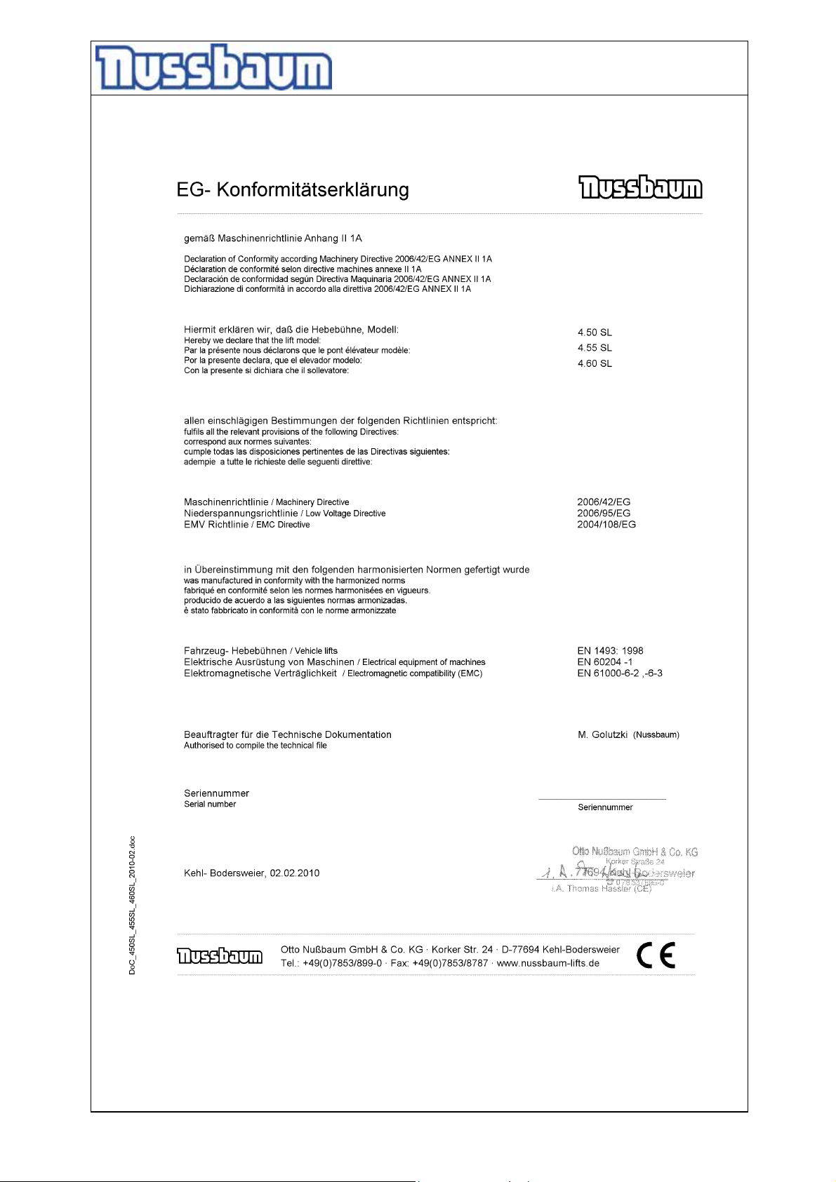
2.5 Declaration of conformity
- 9 -
Page 10
Operating Instruction and Documentation
4.50 SL
3. Technical Information
- 10 -
Page 11
Operating Instruction and Documentation
4.50 SL
3.1 Technical ratings
Capacity: 5000 kg
Load distribution:
Lifting time: approx 1 min. 34 sec.
Lowering time: approx. 50 sec.
Line Volthage: 3 ~/N+PE,400 Volt ,50 Hz
Power rating: 4 x 1,5 kW
Motor rotation: 1420 rotation/Min
Sound level L
Connection by customer 3~/N+PE, 400V, 50 Hz
max. 2:1 in or against the drive on direction
: ≤ 70 dB
PA
fuse 32 Ampere (time-lag fuse)
observe your regulations of your country
Optional: Energy set: Pneumatic connection: air pressure 6-10 bar
Electrical plug: 220V/50hz
3.2 Safety device
1. Safety switching in case the carrying nut breaks
Examination of the carrying nut with a wear-pin into the lifting carriage.
2. Electronic disconnection
If the final position is reached, the lifting platform switched-off
3. Electronic synchronisation
Safety device against unequal run of the lifting carriage
4. Safety catch hook
Safety device against repeated raising if the lifting nut is broken
5. Roll over safety device at the end of the platform
Safety device against falling down
6. Totmann” control
After let go of the buttons, the current movement of the lift stops
Optional:
7. foot protection
Safety device to avoid crushing
8. CE-STOP + acoustic signal
Safety device to avoid crushing
- 11 -
Page 12
Operating Instruction and Documentation
4.50 SL
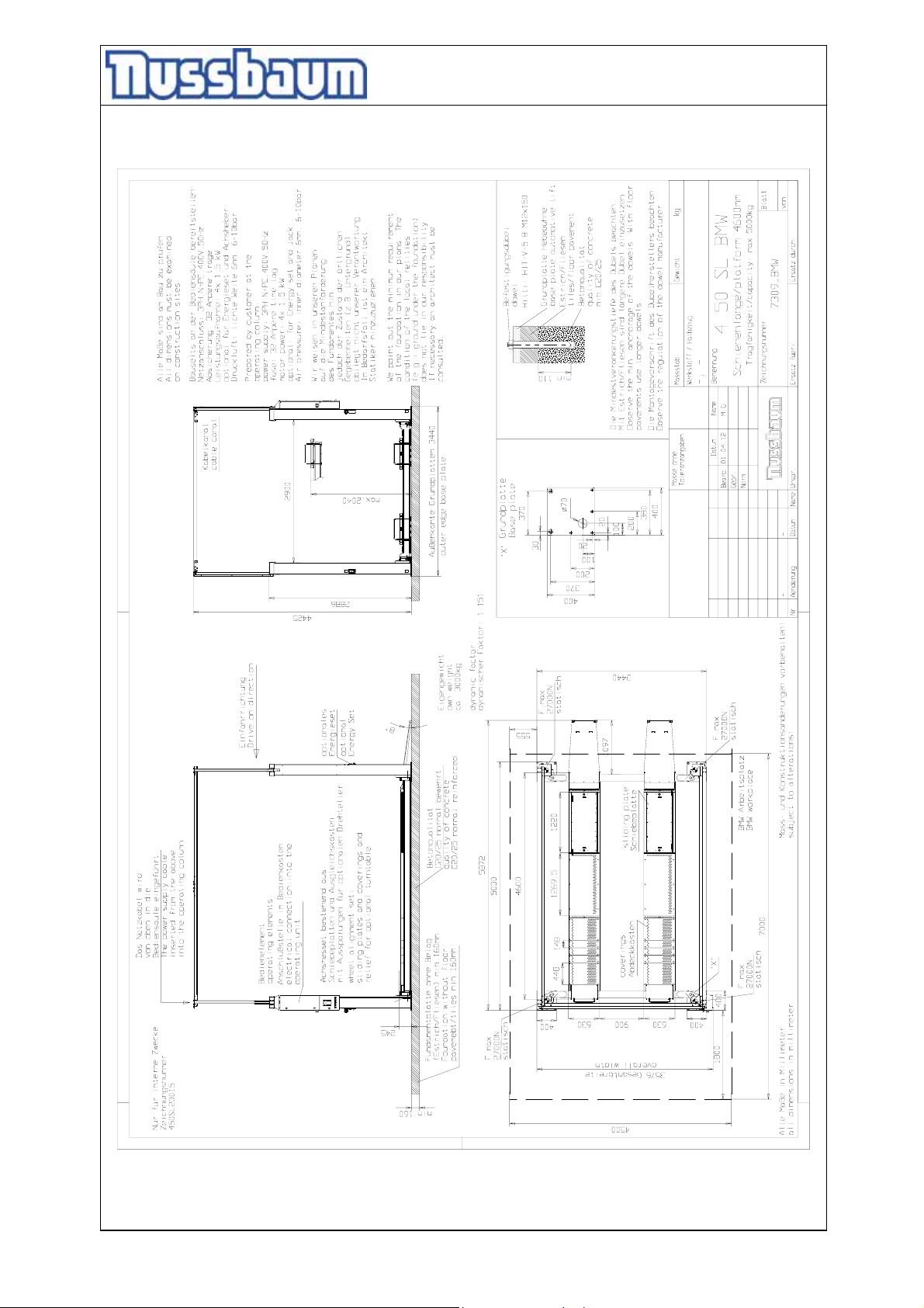
3.3 Data sheet
- 12 -
Page 13
Operating Instruction and Documentation
4.50 SL
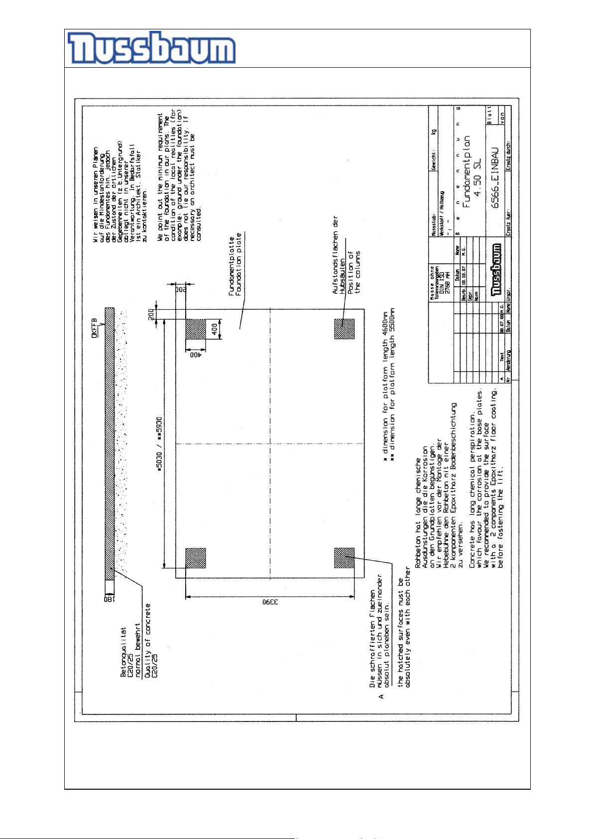
3.4 Foundation diagram drawing
- 13 -
Page 14
Operating Instruction and Documentation
4.50 SL
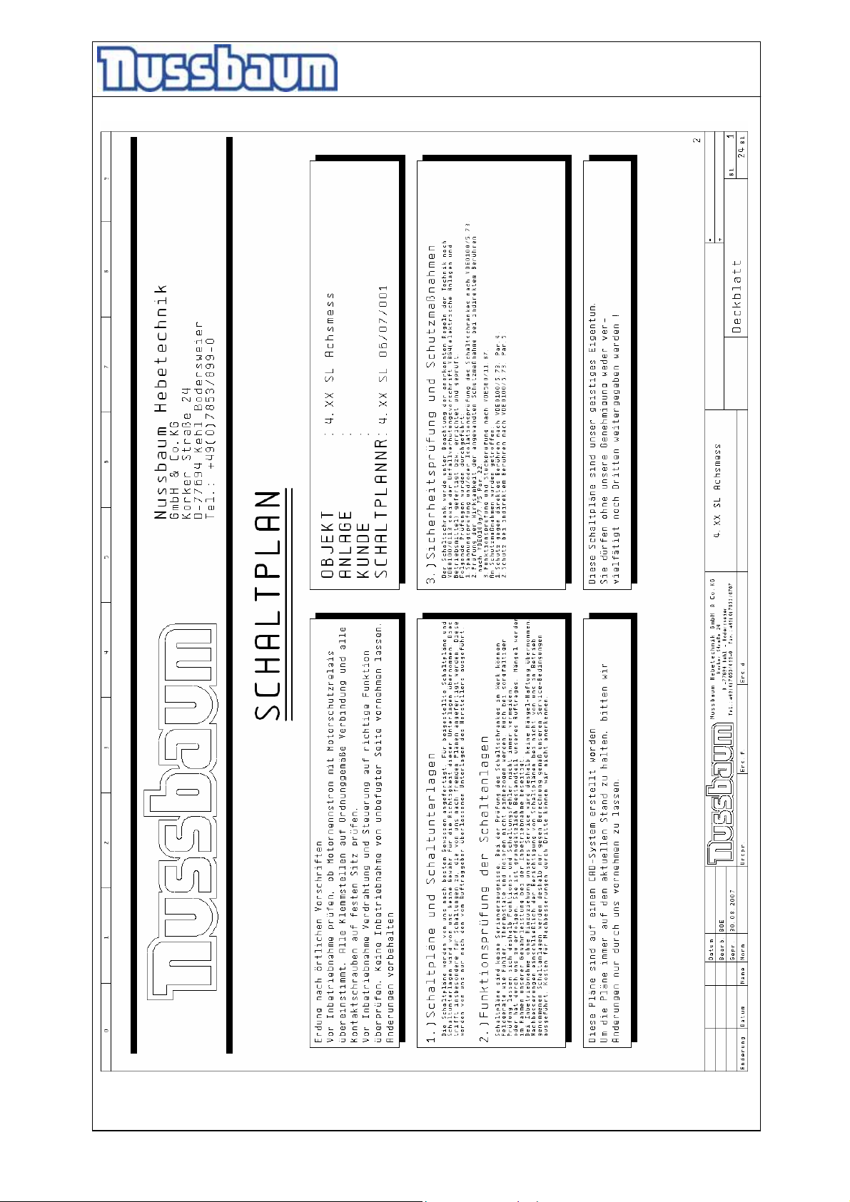
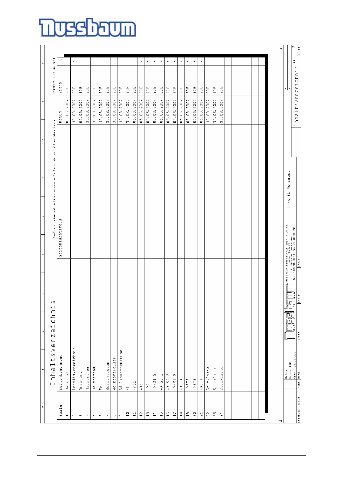
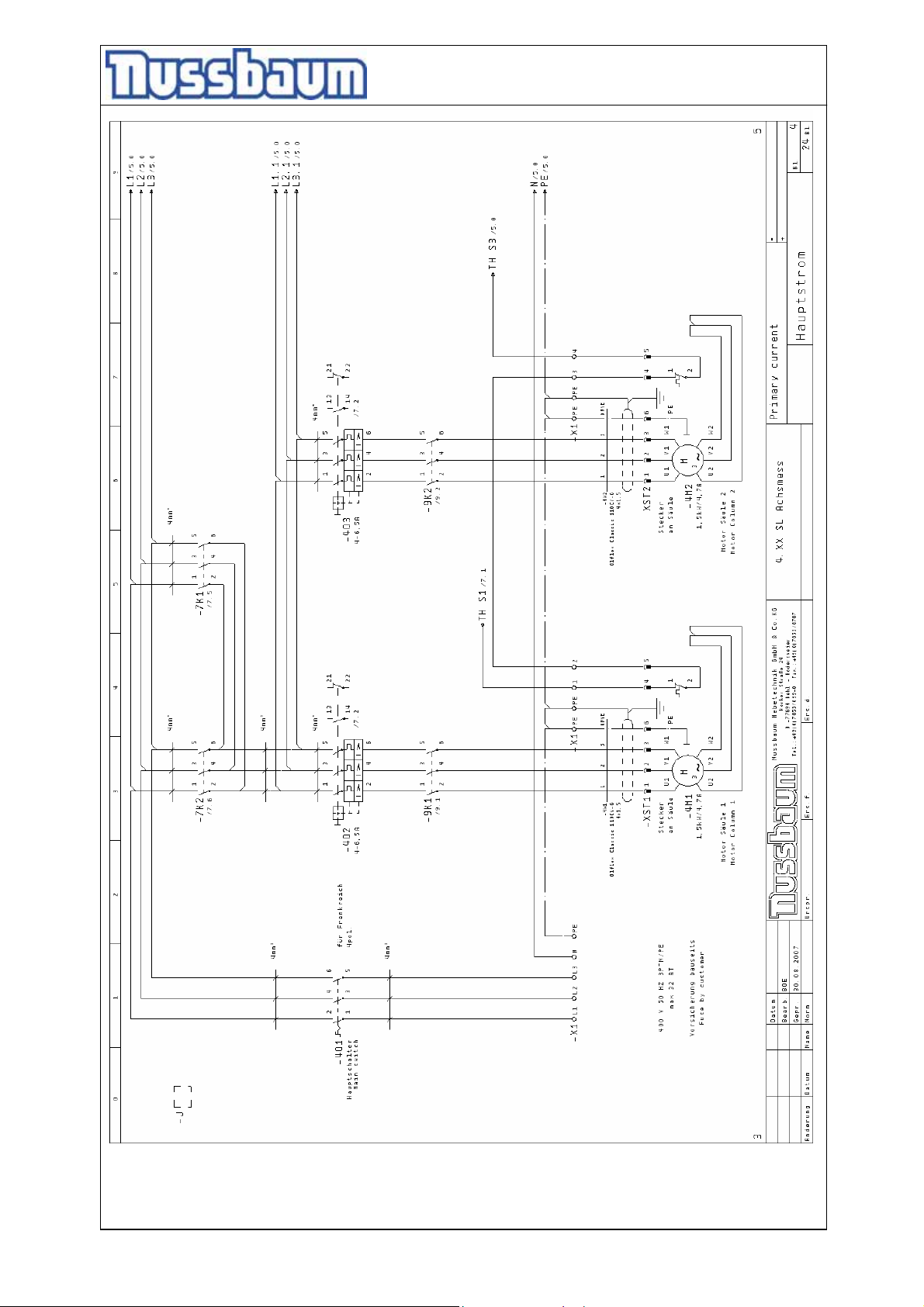
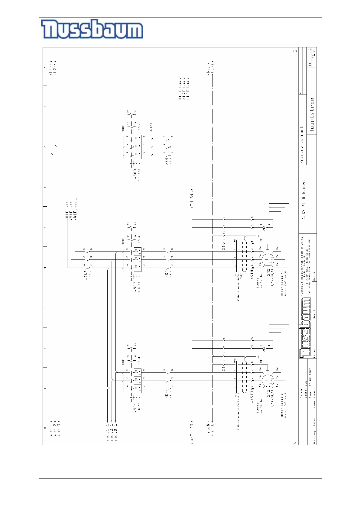
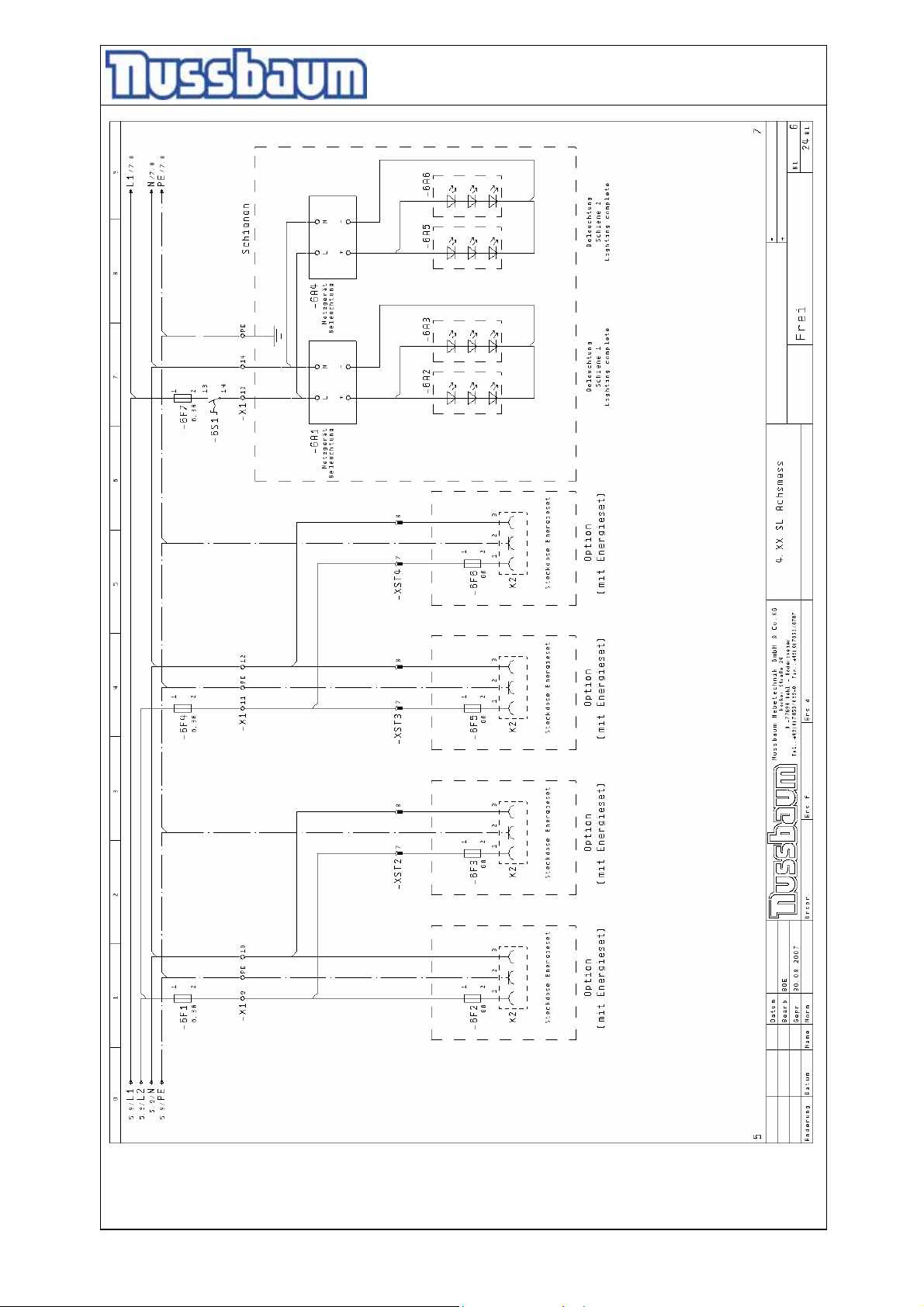
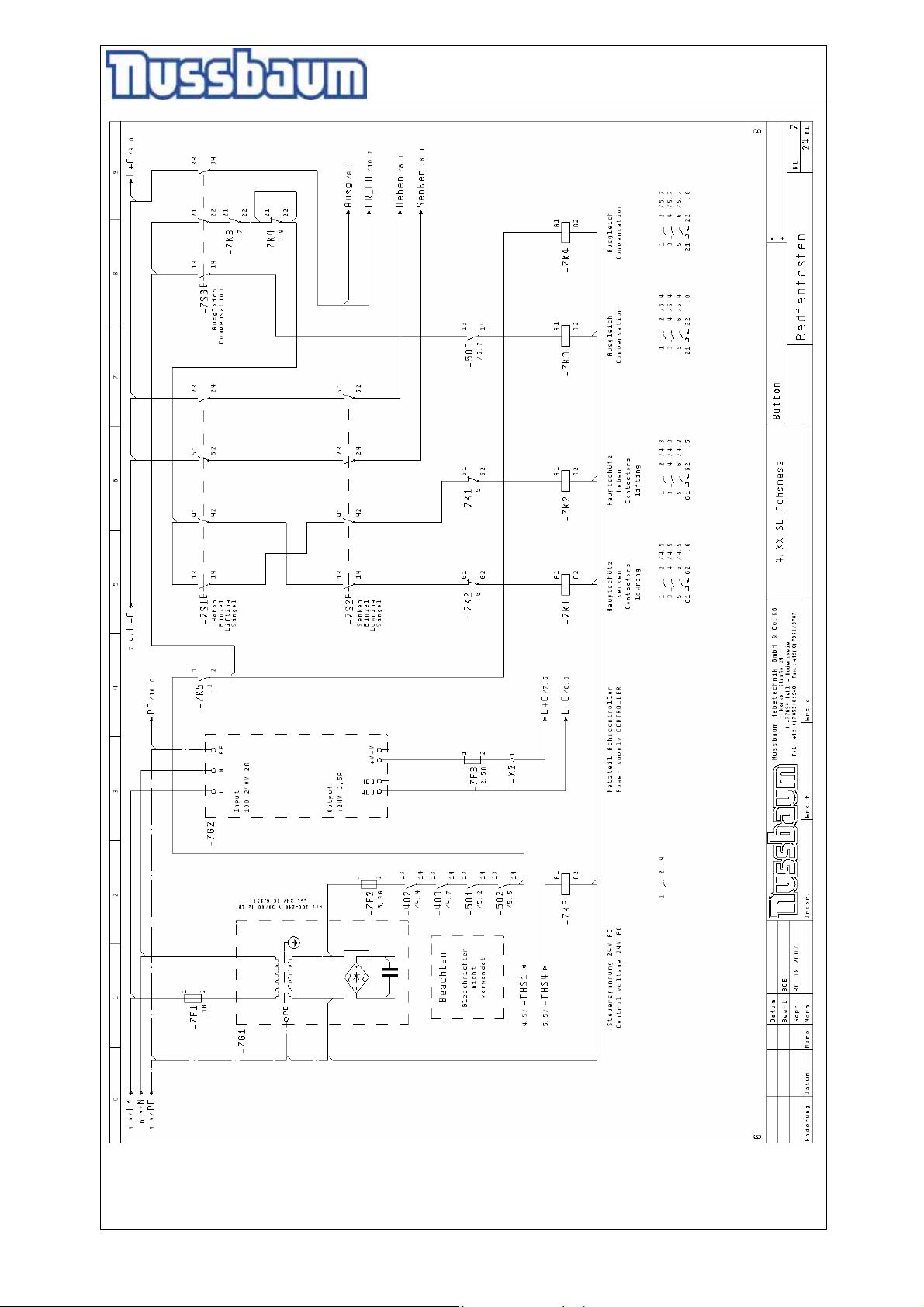
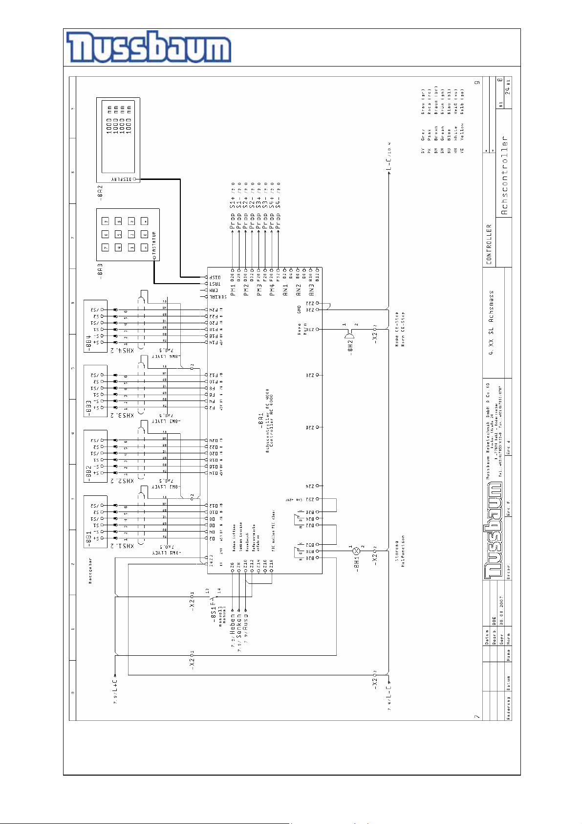
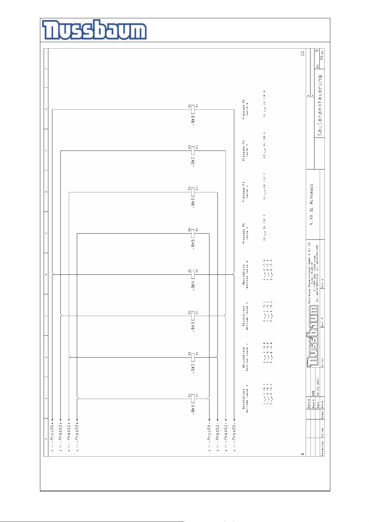
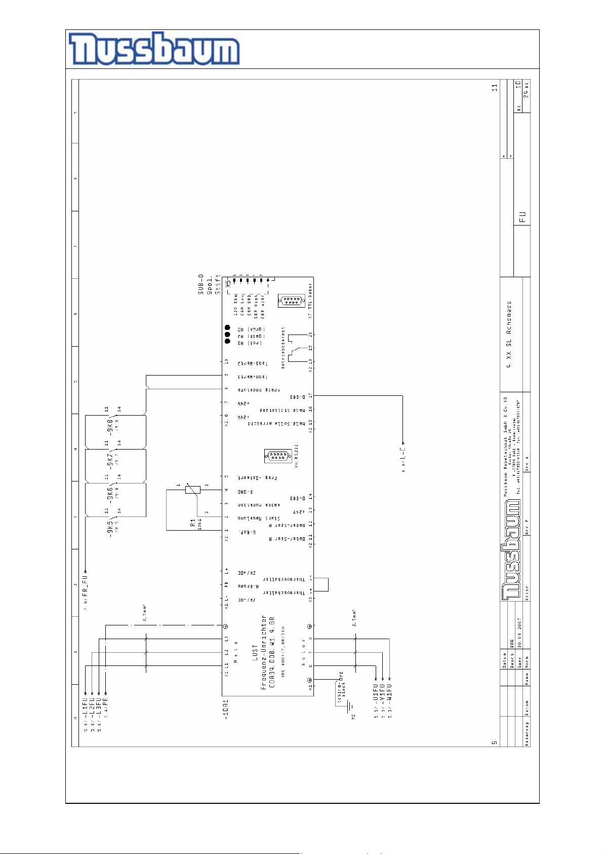
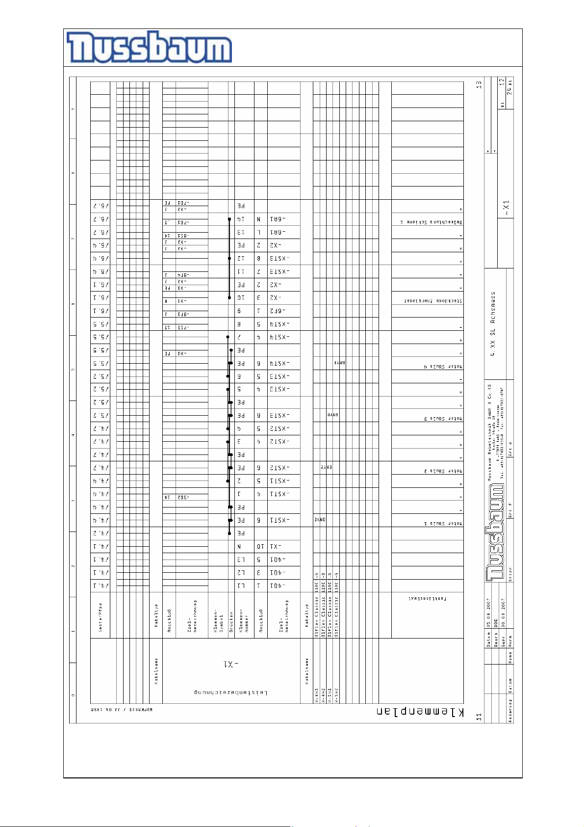
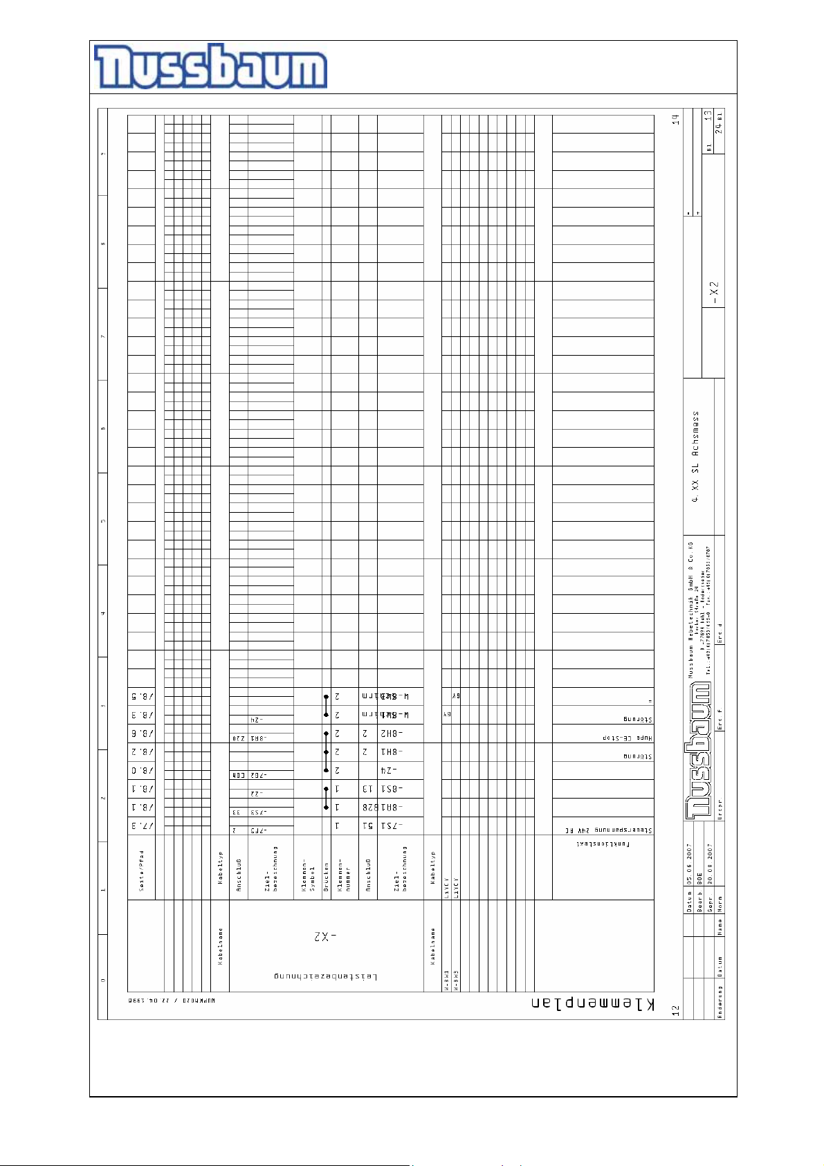
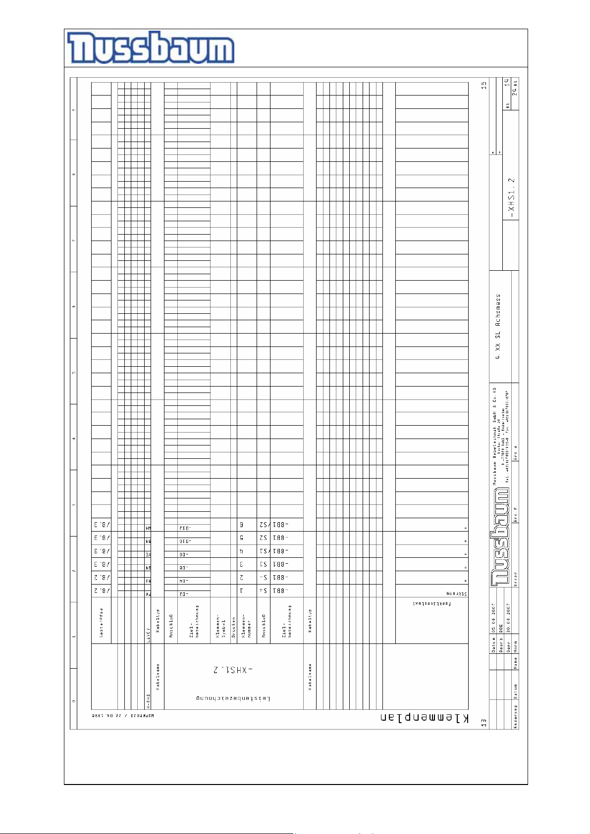
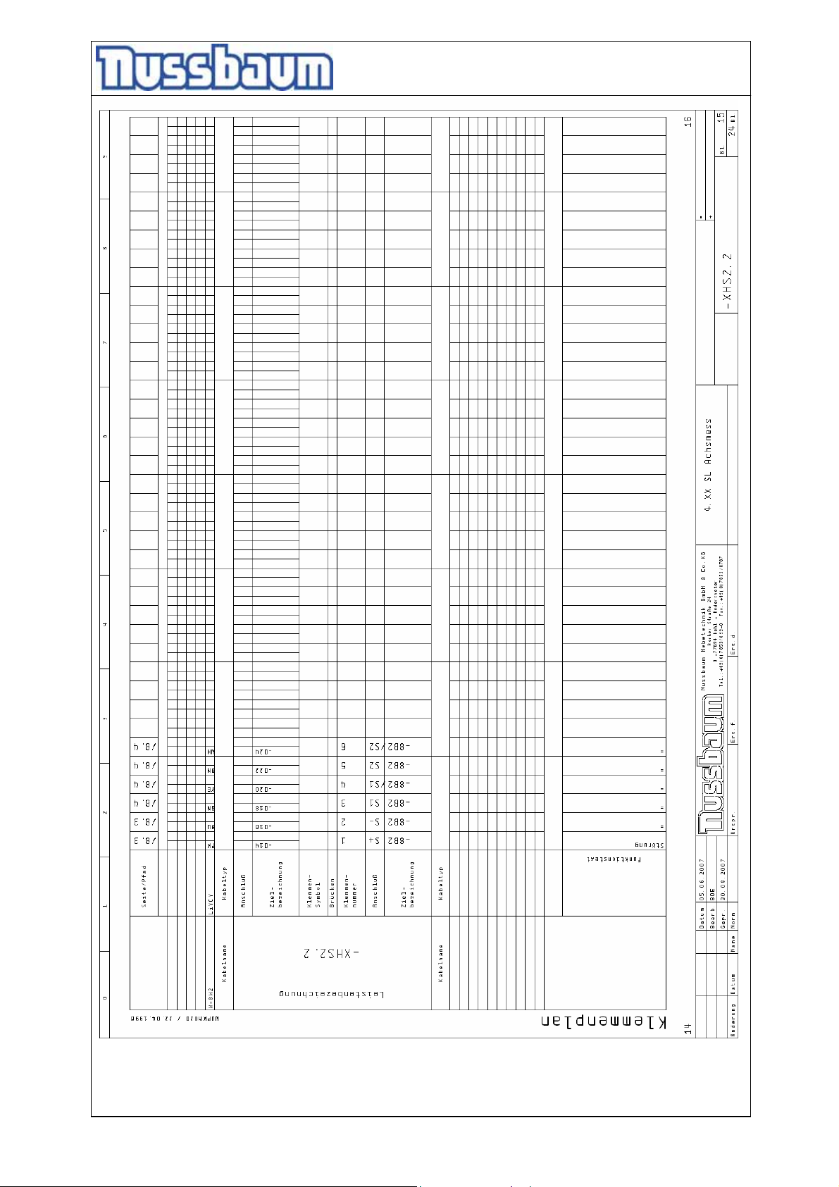
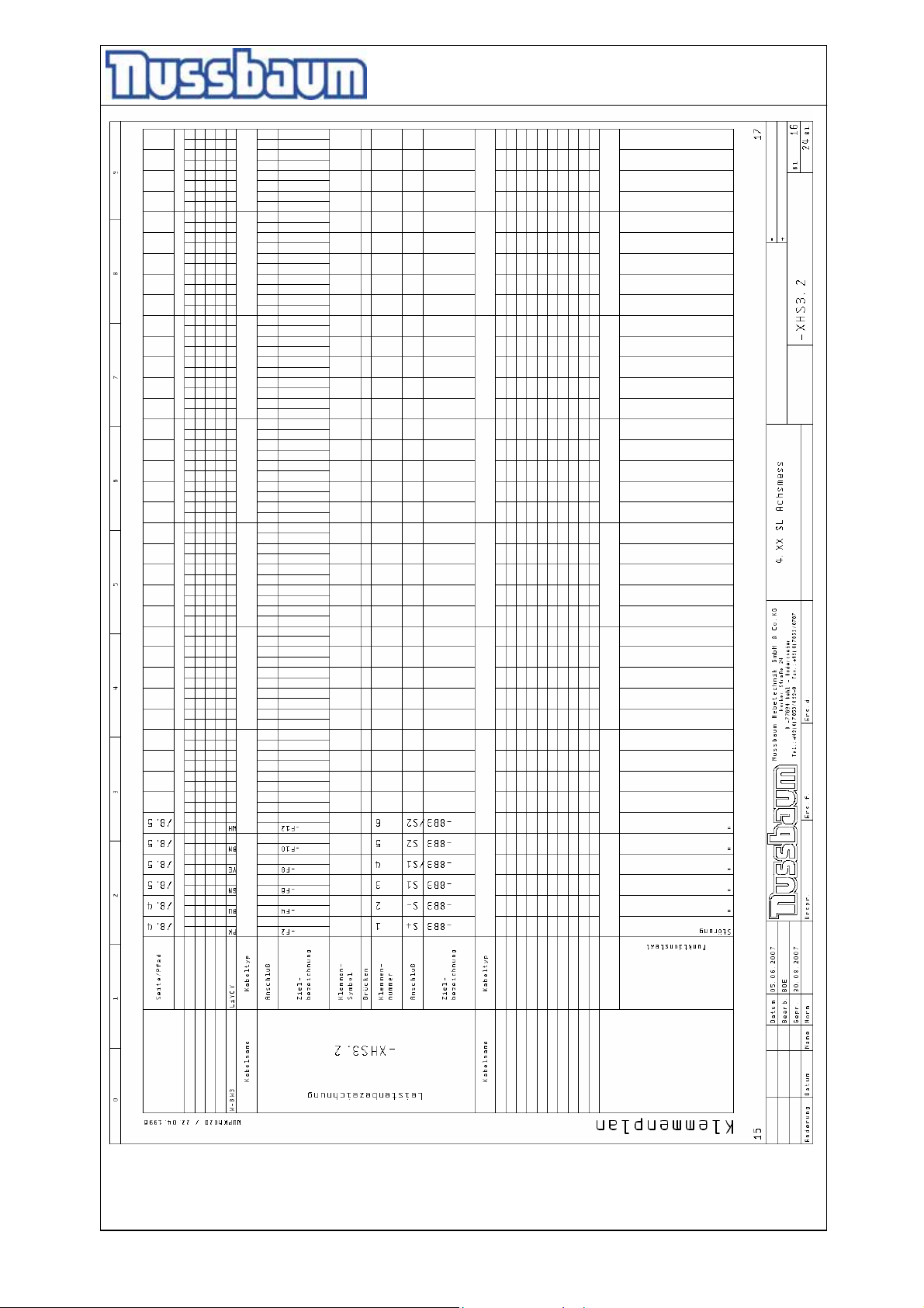
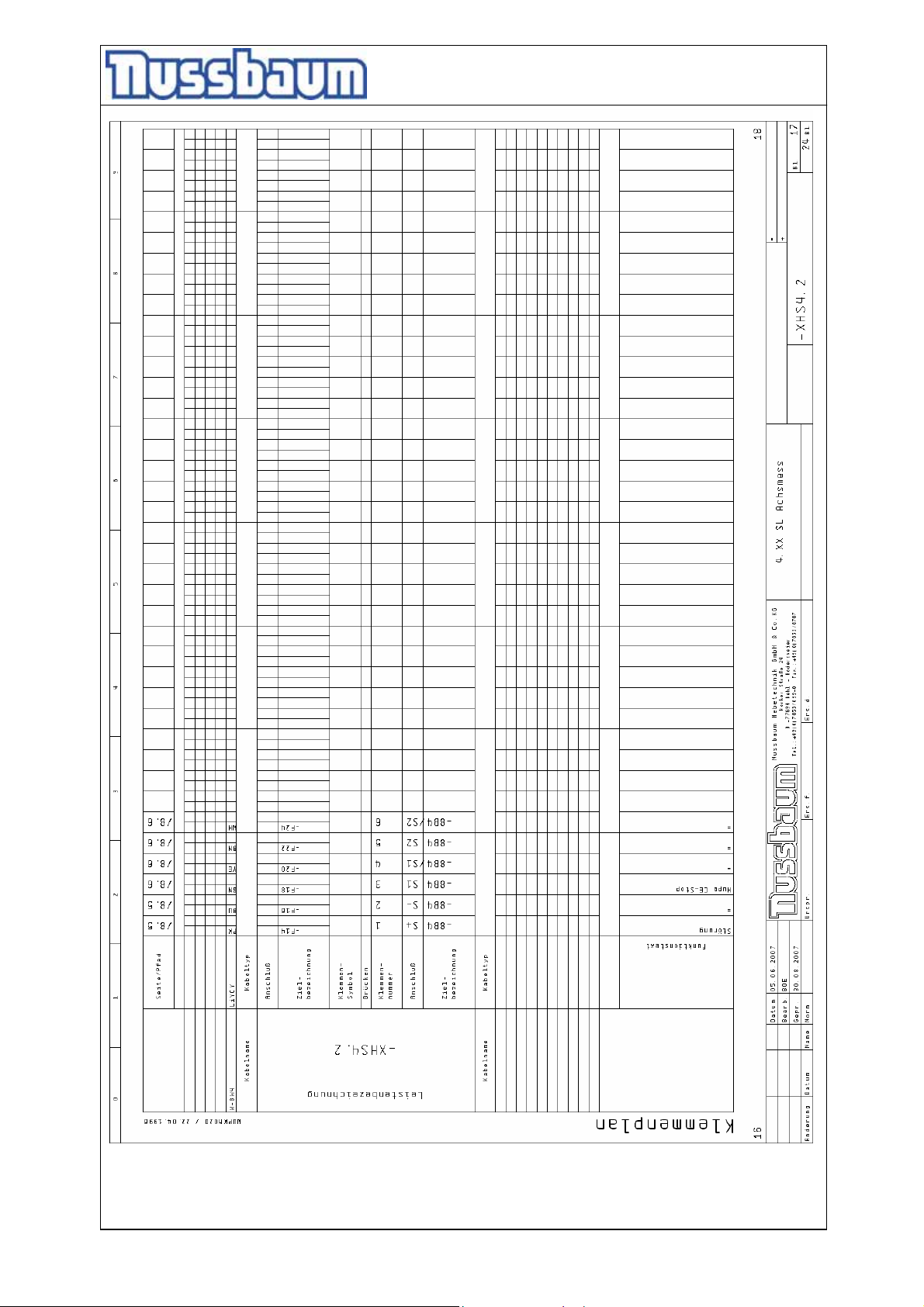
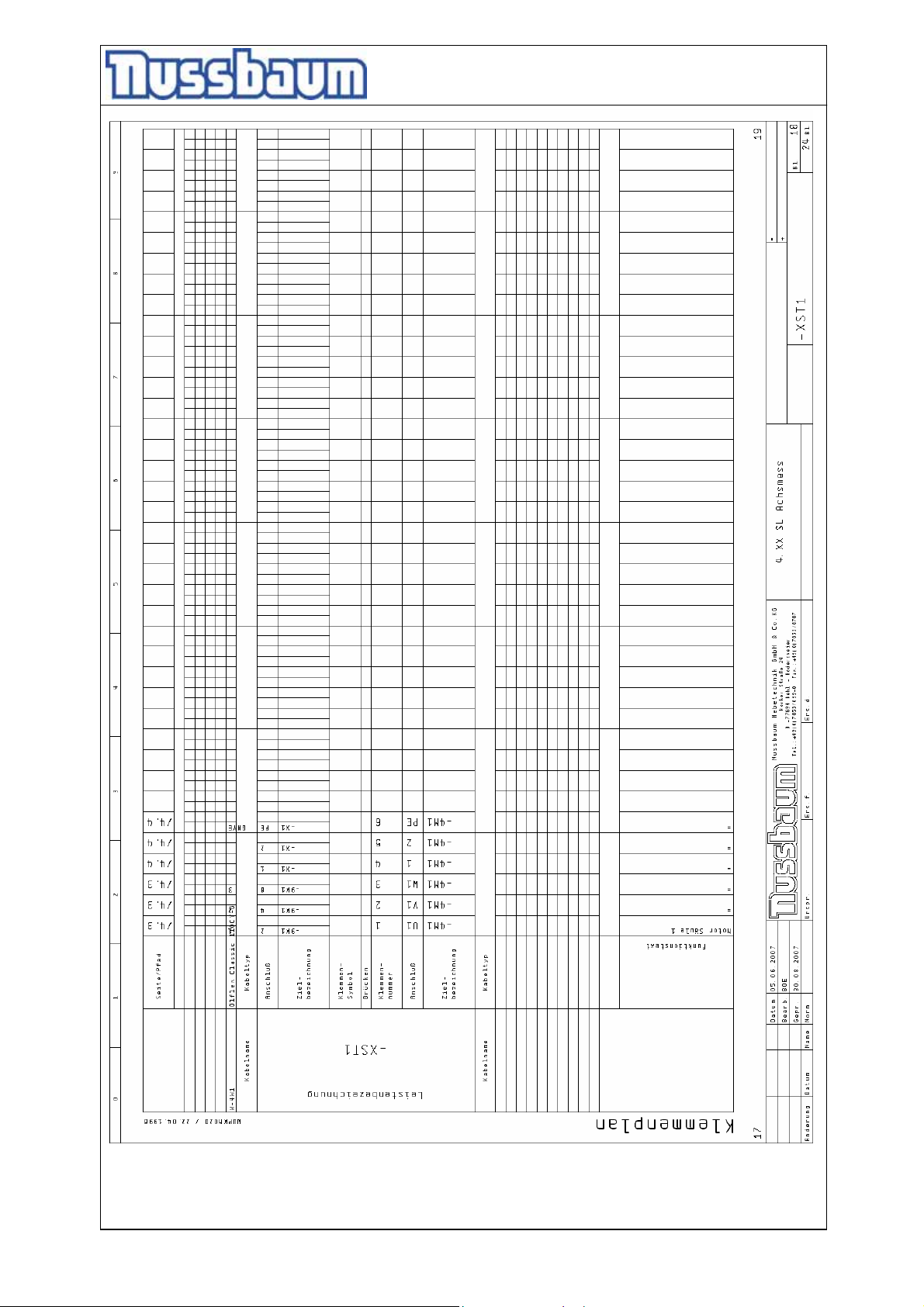
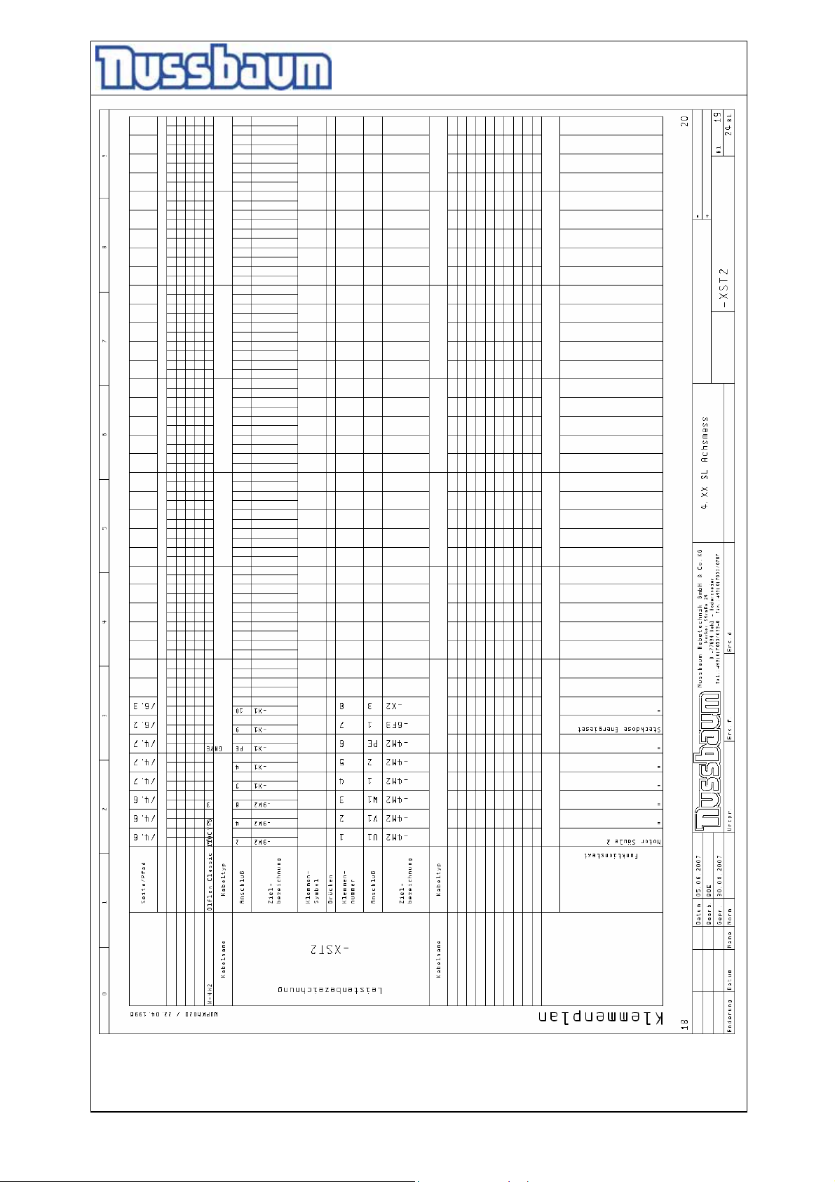
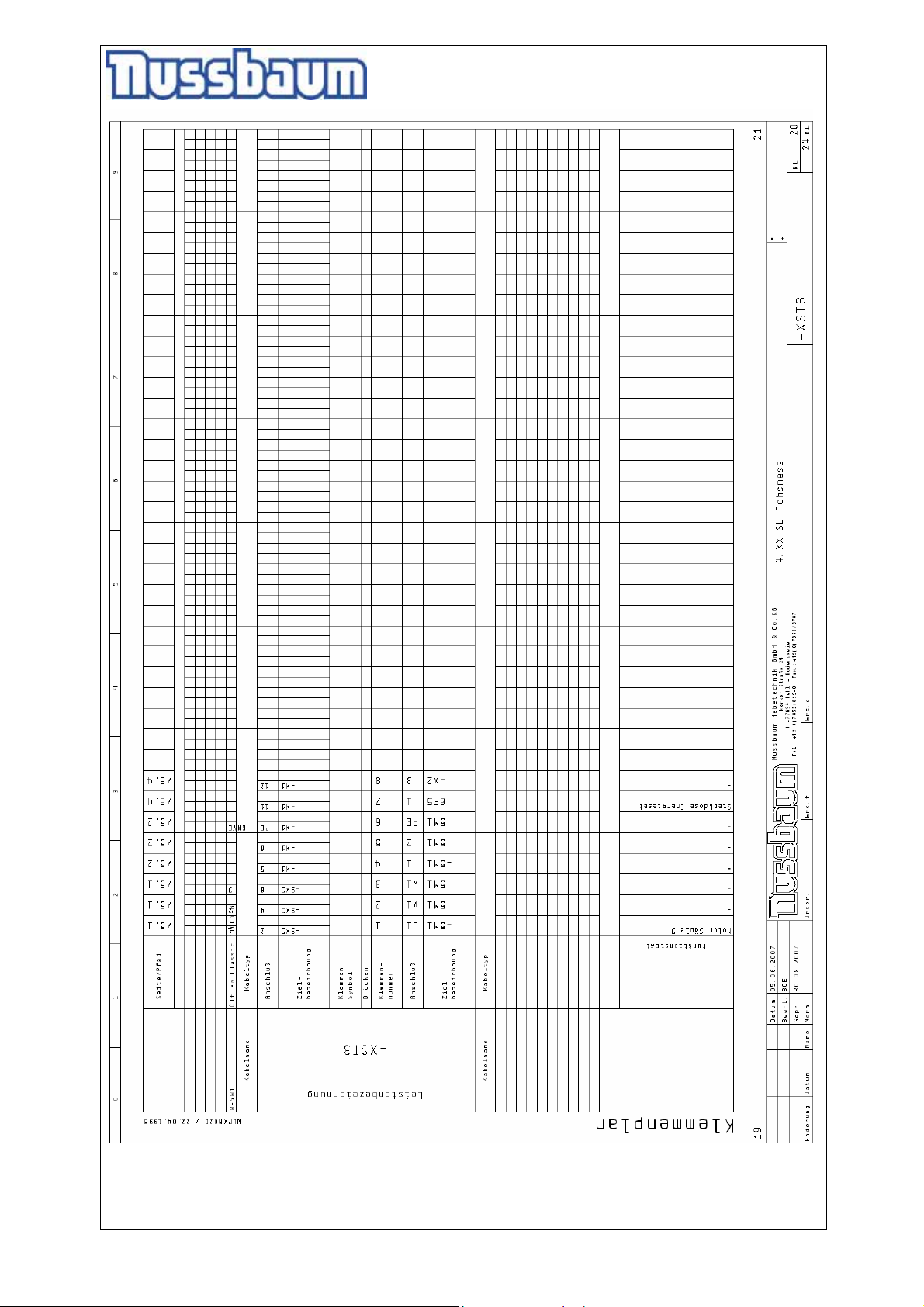
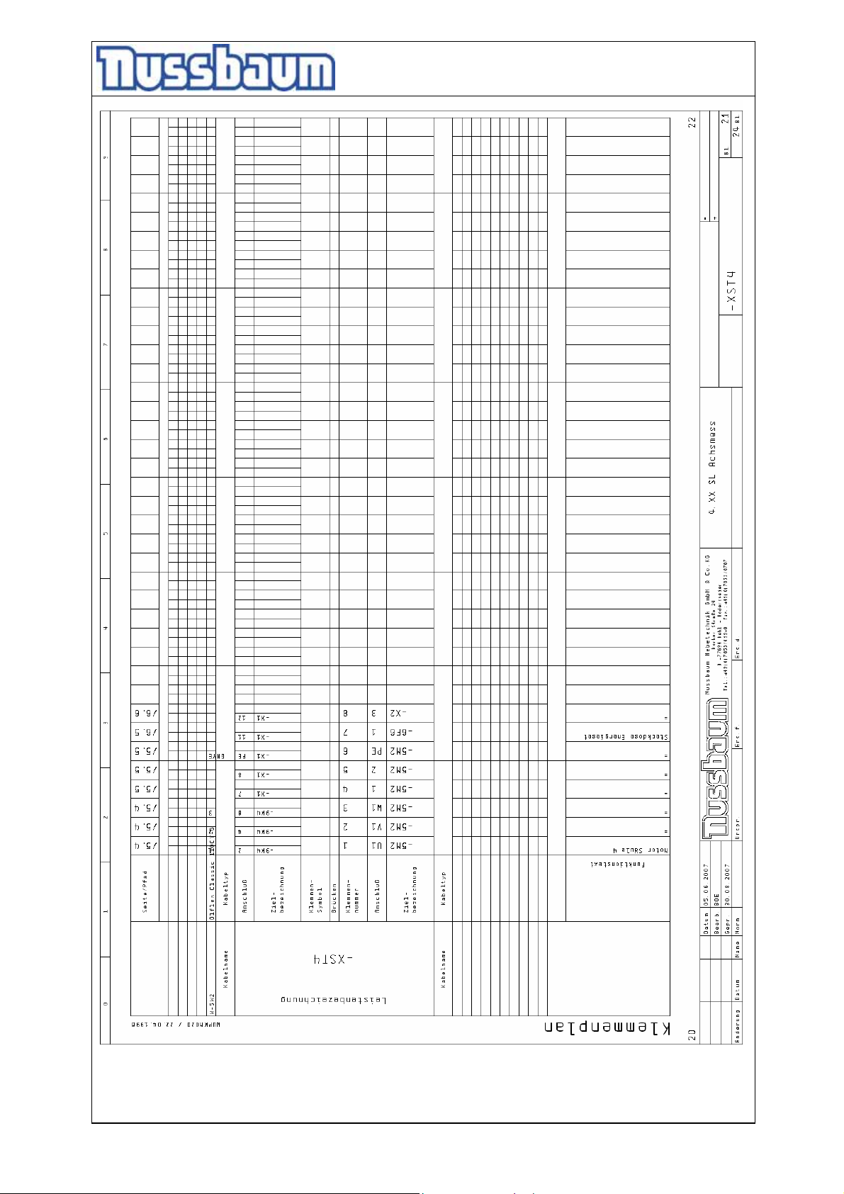
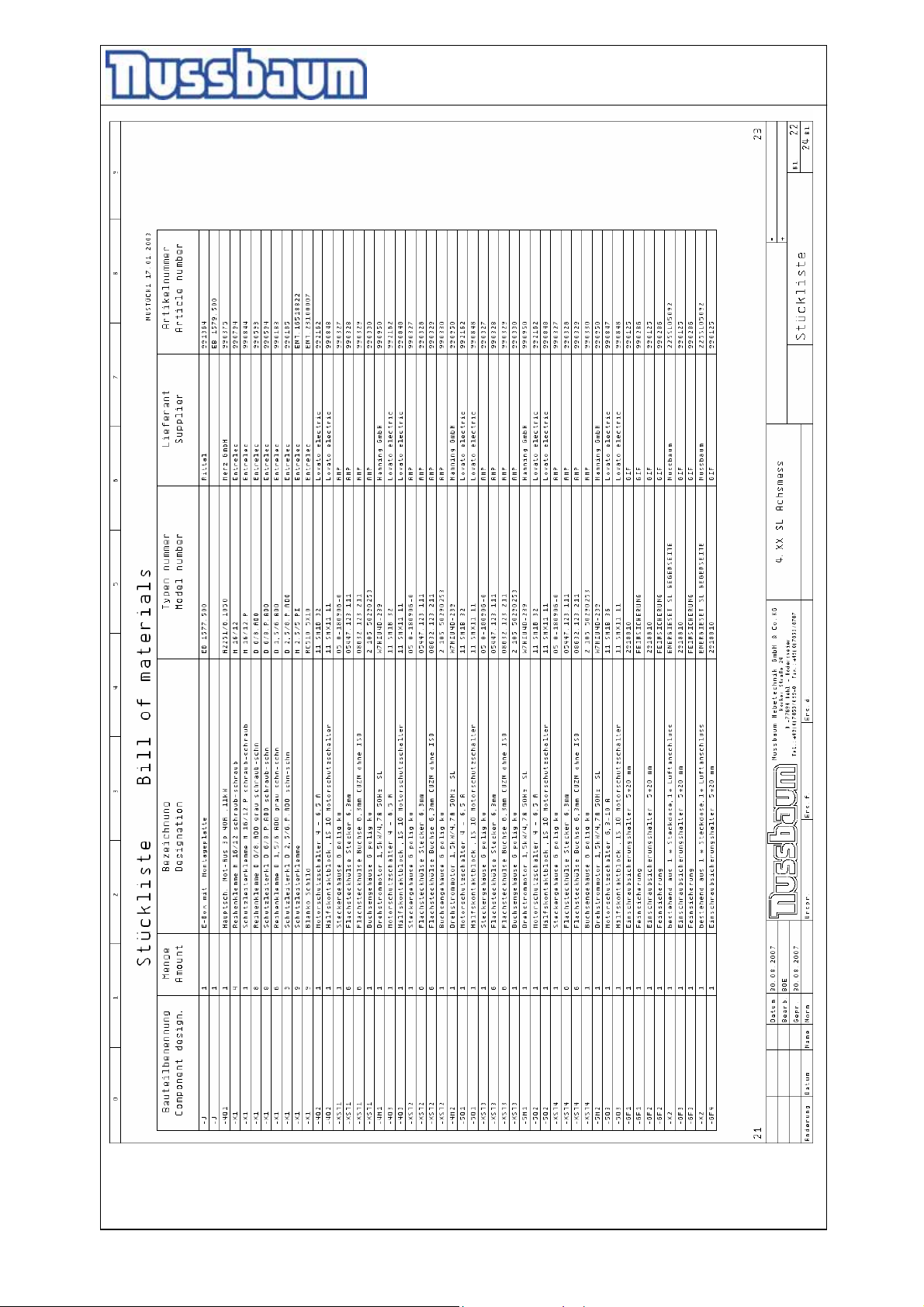
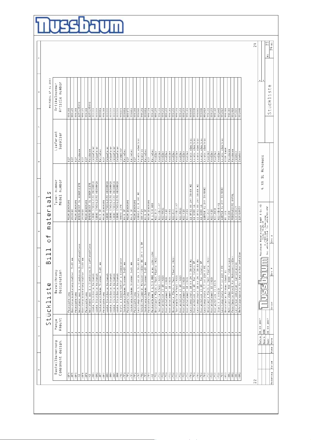
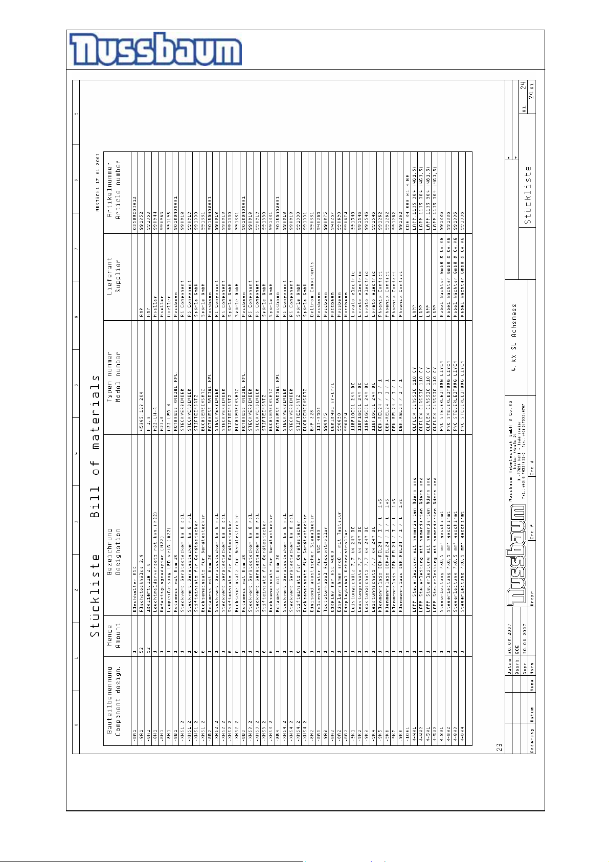
3.5 Electrical diagram drawing
- 14 -
Page 15
Operating Instruction and Documentation
4.50 SL
- 15 -
Page 16
Operating Instruction and Documentation
4.50 SL
- 16 -
Page 17
Operating Instruction and Documentation
4.50 SL
- 17 -
Page 18
Operating Instruction and Documentation
4.50 SL
- 18 -
Page 19
Operating Instruction and Documentation
4.50 SL
- 19 -
Page 20
Operating Instruction and Documentation
4.50 SL
- 20 -
Page 21
Operating Instruction and Documentation
4.50 SL
- 21 -
Page 22
Operating Instruction and Documentation
4.50 SL
- 22 -
Page 23
Operating Instruction and Documentation
4.50 SL
- 23 -
Page 24
Operating Instruction and Documentation
4.50 SL
- 24 -
Page 25
Operating Instruction and Documentation
4.50 SL
- 25 -
Page 26
Operating Instruction and Documentation
4.50 SL
- 26 -
Page 27
Operating Instruction and Documentation
4.50 SL
- 27 -
Page 28
Operating Instruction and Documentation
4.50 SL
- 28 -
Page 29
Operating Instruction and Documentation
4.50 SL
- 29 -
Page 30
Operating Instruction and Documentation
4.50 SL
- 30 -
Page 31
Operating Instruction and Documentation
4.50 SL
- 31 -
Page 32
Operating Instruction and Documentation
4.50 SL
- 32 -
Page 33
Operating Instruction and Documentation
4.50 SL
- 33 -
Page 34
Operating Instruction and Documentation
4.50 SL
- 34 -
Page 35
Operating Instruction and Documentation
4.50 SL
- 35 -
Page 36
Operating Instruction and Documentation
4.50 SL
- 36 -
Page 37
Operating Instruction and Documentation
4.50 SL
- 37 -
Page 38
Operating Instruction and Documentation
4.50 SL
4. Safety regulations
If you use the automotive lift, the German following regulations are to be considered:
BGG945: Examine of automotive-lifts; BGR500 Using automotive-lifts; (VBG14).
Especially the following regulations are very important:
• The laden weight of the lifted vehicle must not exceed 5000 kg for the automotive lift.
Load distribution max. 2:1 in or against the drive on direction.
• While working with the lift the operating instructions must be followed.
• The automotive lift must be in its lowest position (fully collapsed), before the vehicle can be
driving on to the lift. Only then can the vehicle be lifted.
• Vehicles with low clearance or vehicles that are specially equipped should be pre tested to
ensure that they clear the lift ramp to avoid damage.
• Only trained personnel over the age of 18 years old are to operate this lift. (see data sheet
“Record of handing over”)
• No one is to stand within the working area (danger area) during lifting and lowering.
• No one is to be raised or lowed either directly or in a vehicle by the automotive lift.
• No one is to climb onto the automotive lift or onto an already raised vehicle.
• The automotive column lift must be checked by an expert after changes in the construction
have been made.
• Position the rubber pads at the pick-up points under the vehicle as described of the vehicle
manufacturer. (optional: version with Jack)
• Observe the complete lifting and lowering procedure.
• It is not allowed to install the lift in hazardous or dangerous locations (outdoor, washing
bays).
• The main switch must be switched off and locked before work on the vehicle can
commence. This is a safety precaution to ensure that the lift does not move during work.
• The main switch must be switched off and locked before any maintenance or repair work
on the automotive lift itself can be carried out.
- 38 -
Page 39
Operating Instruction and Documentation
4.50 SL
5. Operating instructions
The Safety Regulations must be observed and adhered to while working with the
automotive lift. Read the safety regulations in chapter 4 carefully before working with
the lift!
5.1 Lifting the vehicle
• Drive the vehicle onto the middle of the lift.
The complete wheels must be standing on the platform, otherwise the vehicle can fall
down.
• Secure the vehicle against rolling, put into gear, apply the hand brake.
• Control the dangerous places of the lift and be sure that there are no objects or people in
the immediate area of the lift or on the lift.
• Switch on the main switch. Raise the vehicle Press the button „Lifting“.
• Raise the vehicle to the required working height. Press the button “lifting“ .
• The roll over and roll back safe device must be activated when the lift was slightly raised.
• Observe the complete process.
Check the safe position of the vehicle on the platform.
The automotive-lift can regulate several times depending upon distribution of the load.
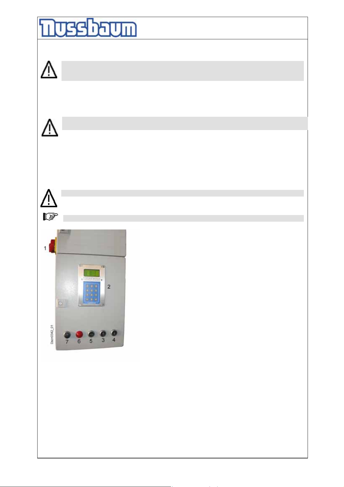
pic: operating elements
1 Main switch
2 Keyboard and LC-Display
3 Button „Lifting“
4 Button „Lowering“
5 Button „Equalisation“
6 Red light „Malfunction“
7 Switch „Lighting“ (optional)
5.2 Synchronism of the automotive lift
• The lift is equipped with an electronic synchronism.
• At the columns are potentiometer which recognizes the actual-position of the spindle.
• A lifting carriage is faster like the other lifting carriage. No matter whether when lifting or
lowering. The electronic control system observe this procedure and stops the fastest
carriage so long until all carriage have the same height again. The permitted regulation
range is 18 mm.
- 39 -
Page 40
Operating Instruction and Documentation
4.50 SL
5.3 Lowering the vehicle
• Control the dangerous places of the lift and be sure that there are no objects or people in
the immediate area of the lift or on the lift.
• Before the lift reaches its lowest position, the lift stops automatically (CE-Stop). After the lift
has stopped, check the danger area around the lift. Press the button “lowering”. An
acoustic signal will sound as the lift is further lowered. This is to warn against the risk of
crushing as the lift is slowly lowered to its lowest position.
• Drive the vehicle in to the working height or to the lowest position.
The automotive-lift can regulate several times depending upon distribution of the load.
• Drive the vehicle from the platform.
• Observe the complete process.
6. Troubleshooting
If the lift does not work properly, the reason might be quite simple. Please check the lift for the
potential reasons mentioned on the following pages. If the cause of trouble still cannot be found,
please call technical service.
Self-employer repair-working is prohibited.
Repairs at the security devices of the lift as well as repairs and examinations of the
electrical fittings are forbidden.
Repairs at electrical system may be accomplished only by expert persons.
Problem: The lift does not lifting and not lowering!
possible causes: remedying:
No electrical power supply
The main switch is not switched on
Press button „lifting“ is defective
The fuse is faulty
The feed line is cut
The motor is overheated
The plug connection between the motors are loose
The lift is not in the regulation range
V-Belt is torn or defective
Motor defective
Examine the power supply
Examine the main switch
Examine the press button
Examine the fuse, replace it if
necessary
Examine the feed line
Let it cool down
Examine the plugs
Equalize manually (see chapter 6.4)
Shut down the lift. Replace the
V-belt and adjust it again (see
chapter 7.3)
Make an emergency lowering (see
- 40 -
Page 41
Operating Instruction and Documentation
4.50 SL
Battery on the control board is empty. The lift drive
out of the synchronism window
Problem: The lift does not lifting!
possible causes: remedying:
Only 2 phases active
V-Belt is torn or slack
The lifting nut is broken, the safety device(catch
hook) is active, the lift is not in the regulation range
and the lift has switched off
Top limit switch is active
chapter 6.1)
Phone the service partner
Examine by an electrician
Shut down the lift. Replace the
V-belt and adjust it again (see
chapter 7.3)
Shut down the lift and phone the
service partner
Only lowering procedure is possible
Problem: The lift does not lowering!
possible causes: remedying:
the bottom limit switch is active
The lifting carriage or a platform is driven on a
obstacle
V-Belt is torn or slack
Only lifting procedure is possible
Equalise the lift manually
Shut down the lift. Replace the
V-belt and adjust it again (see
chapter 7.3)
6.1 Emergency lowering
In case of power failure the lift can not lowered with the motors. In this case there is the possibility
to lower the lift manually. Switch off the main switch and lock it. Remove all four cover of the vbelt pulleys. Turn alternately (5cm) the nuts on the top end of the spindle anticlockwise until the
lift is in the lowest position. After it, remove the vehicle.
The emergency lowering must only carried out by persons which are instructed to
using the lift. Please refer to the regulation “Lowering the vehicle”.
Procedure the emergency lowering
• Switch off the main switch and lock it.
• Remove all four cover of the v-belt pulleys.
• Turn alternately (5cm) the nuts on the top end of the spindle anticlockwise until the lift is in
the lowest position. After it, remove the vehicle.
- 41 -
Page 42
Operating Instruction and Documentation
4.50 SL
In case of disturbance or defect, secure the lift against authorized person. Phone your
service partner.
6.2 Driving onto an obstacle
If the platform or the lifting carriage is lowering on an obstacle, the motor from this side will be
locked. The lift switched off if the lifting carriage are not more in the regulation range
(approx. 50 mm).
An additional protection is the temperature control system in the motor. It interrupt the
electrical circuit when it is overloaded. You can not work with the lift. Cool down
approx. 5 – 10 min. dependently on the outside temperature.
After the locking of the motor, examine the V-belt, if necessary exchange it. Call your servicepartner.
6.3 Function of safety device
The lift is equipped with a safety switching, which controls the wear of the main nut.
If the lifting nut is broken, a safety nut which is conducted loose in the spindle, carries
the load. After a break of the nut, the lift can only once being lowered in the lowest
position. If the lift has reached the lowest position it is not possible to raise the lift again.
The lifting carriage of the broken side gets mechanically locked. During the lifting the
other side is driving out of the regulation range and switched off the lift. You can not
work with the lift anymore. Call the service-partner.
If the safety device is active, Shut down the lift and phone your the service partner!
Switch off the main switch at all repairs and disturbances!
The electrical system may only be opened by trained persons!
6.4 Manually equalisation of the carriage
The lift is equipped with a position measuring system which guarantee the
synchronisation of the lift. The electrical control recognises if one lifting carriage is
approx. 20 mm earlier at the definite height. The electrical control stopped the motor of
this carriage until both carriage have the same height again. After it both motors are
working together again.
If the carriages of the lift are driving out of the regulation range/switching off window
of approx. 5 0mm), the electrical control recognises this and
switched off the lift.
To reach the normal function of the lift you must equal manually the carriages. Remove
the cover of the V-Belt pulley at the top of the lift. Equal the lift: turn the nuts until the
carriages have the same height.
• Carry out the equalisation with the lift only without load.
• Open the electrical box.
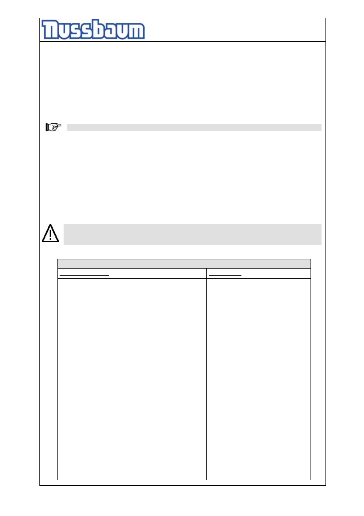
• See the DIP-switches on the controller (Pos.2).
- 42 -
Page 43

Operating Instruction and Documentation
4.50 SL
Pic 4: DIP-switches on the board.
LED (A) switches off in case
of malfunction
LED (B) switches off in case of
malfunction in the measure
systems. (redundant: examine the
LED switches off in case the
voltage of the processor is
under 5Volt
LED blinks to the rhythm of
1 sec under normal
operational function
„controller
DIP-switches
Pos. 1
Reset
„Monitoring controller
PIC“
Only trained and authorized staff is allowed to work with the DIP-switches! The mainswitch has to be switched off!
• DIP switch 5 (regulation ON/OFF)
• DIP switch 1 (only column 1 moveable)
• DIP switch 2 (only column 1 moveable)
• DIP switch 3 (only column 1 moveable)
• DIP switch 4 (only column 1 moveable)
example: Equal the column 1:
• Equalization the column 1 as follows:
• Move the DIP switch 5 on position “off” (regulation off)
• Move the DIP switch 1 on Position „ON“ (DIP switch 1 for column 1)
• Press the button „lifting“ or „lowering“ until the column has the same height as the other
columns.
• Move the DIP switch 1 on position „off“.
• Move the DIP switch 5 on position „on“ (regulation on).
• If necessary repeat the procedure with the column 2,3 and 4 until all columns (lifting
carriage are on the same height.
• Close the electrical box.
6.5 Driving to the Reference point
After 50 working steps shows the display „Referenzpunkt anfahren” (Drive to the reference point“.
Now, it is necessary to drive the lift to the reference point, because the height of the carriage can
be examined.
This can be achieved by a variety of factors sturgeon (dirt, slack, interference pulses, etc.)
• Lower the lift into the lowest position
• Drive the vehicle from the platform
Pos. 3
Reset
“
Pos. 2
- 43 -
Page 44
Operating Instruction and Documentation
4.50 SL
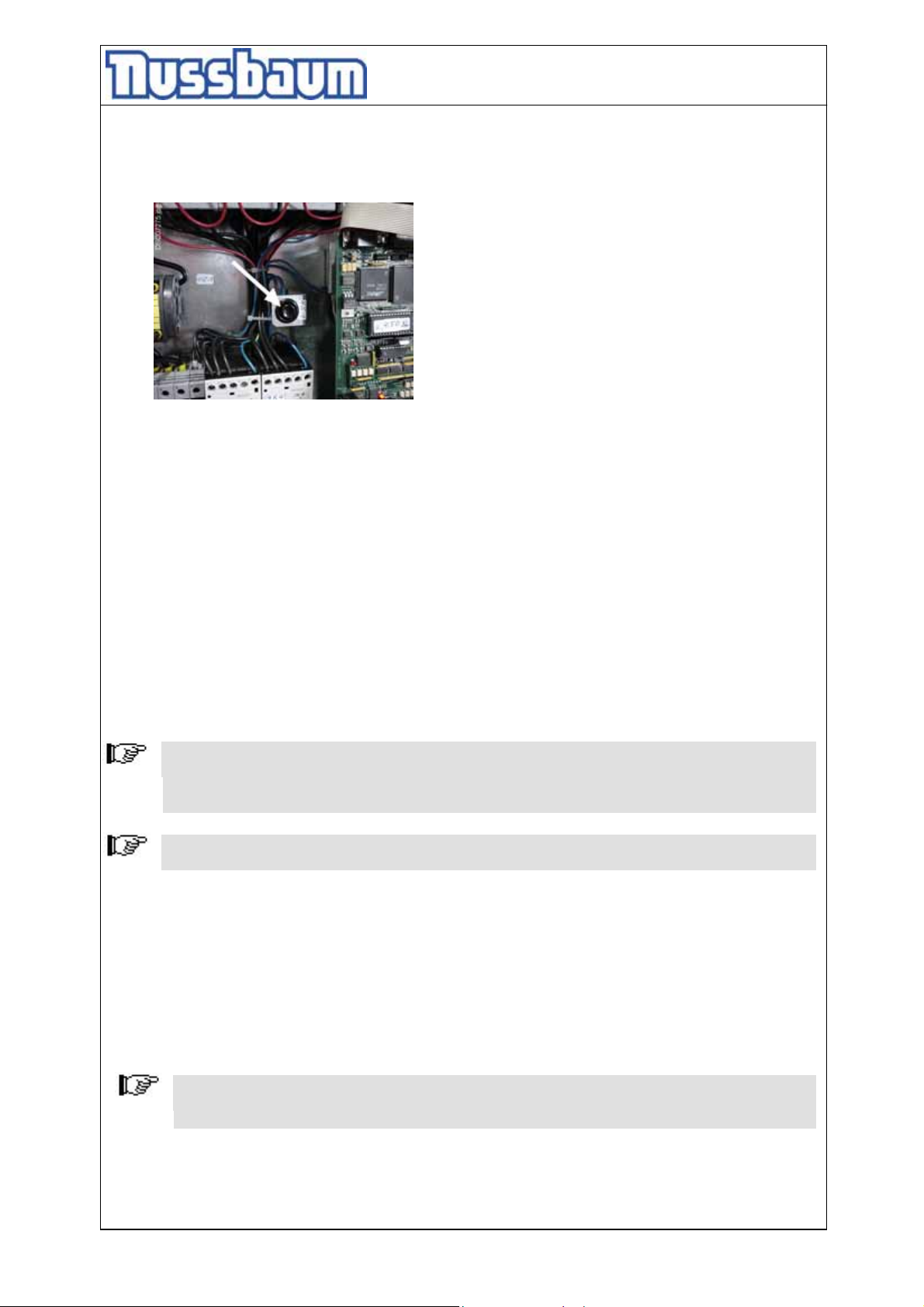
• Open the electrical box.
• Press the button (see pic 5) and hold it pressed and press simultaneously the button „lifting“
until the lift stops at the reference point. Turn off the main switch.
pic 5: button „reference point“
The reference point is marked at every column. Examine the points with the carriage.
In case the level of the carriage and the reference point is not on the same height, level out
manually the carriage at the spindle until the level is ok. In this case the main switch must be
turned off.
Remove the cover at the top of the columns and turn the spindle with a suitable tool until
the carriage is on the „reference point“.
switch power back and push on the keypad # enter 1234 and #, with the * go to
menu point "reference point" and enter #
now confirm with # again.
push * several times to get to the menu point "return" and confirm with #
finished.
7. Inspection and Maintenance
Before conducting maintenance work, preparations must be made to ensure that
during maintenance and repair work there is no risk to the safety of people working on
or around the lift and also that there is no risk of damage to equipment being used on
or around the lift.
German legal guidelines : BSV (Prescription of working tools) + BGR500 (Work with
working tools)
To guarantee the utmost availability and to ensure that the lift remains functional,
maintenance work contracts are organised between our clients and their local retailers.
A service must be performed at regular intervals of 3 months through the operator in
accordance with following service manual. If the lift is in continuous operation or in a dirty
environment, the maintenance rate must be increased.
During daily operation the lift must be closely observed to ensure that it is functioning
correctly. In the case of malfunction or leakage the technical service must be informed.
7.1 Maintenance plan of the lift
Before beginning any maintenance work isolate the power supply. Secure the main switch
(lock it). Secure the danger area around the automotive lift and secure the lift against
unintentional lowering.
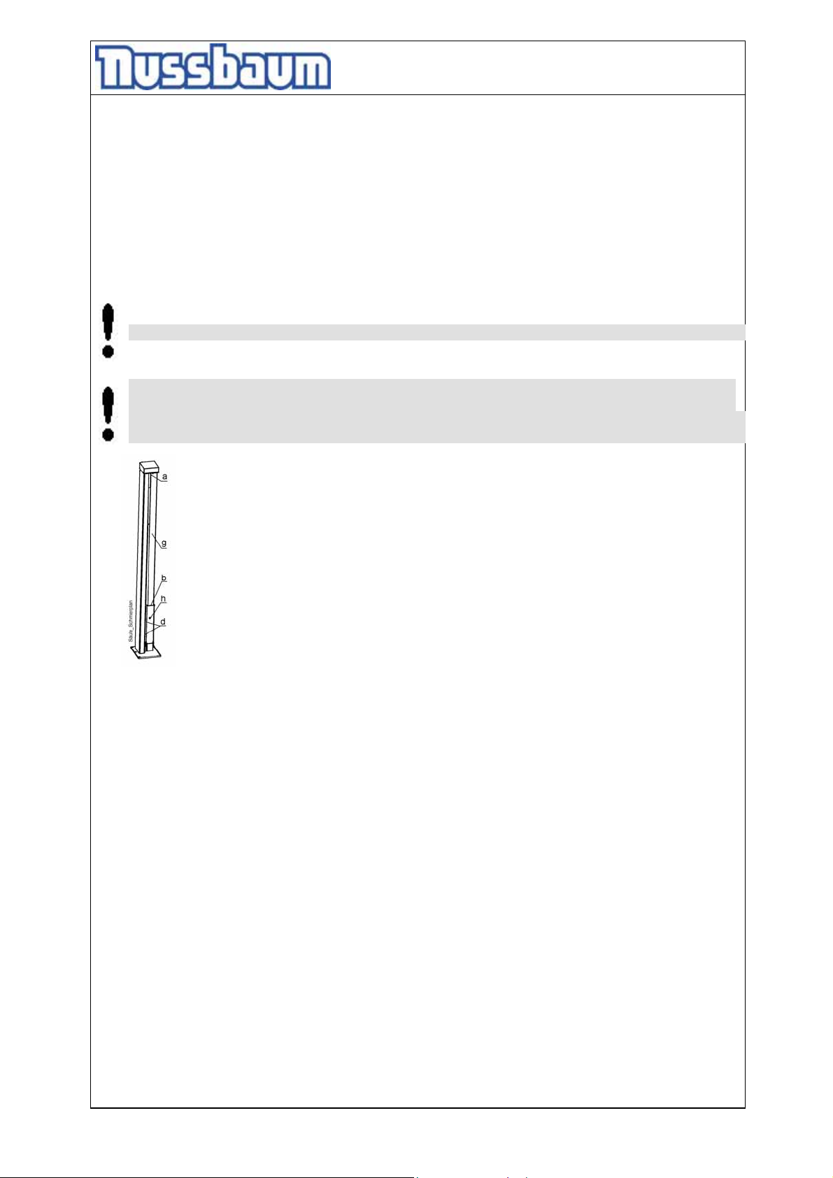
a Grease the spindle bearing annually with a multipurpose fat.
Remove the cover of the spindle (see g).
- 44 -
Page 45
Operating Instruction and Documentation
4.50 SL
b Oiling the spindle and the lubricating felt between the carrying nut and the centring of
the spindle one time a month with a thin oil as SAE15W40.
Attaching twice lifting and lowering the lift in the end position. After lifting and lowering
the lift with load.
The lubricating interval has to be carried out at every maintenance. If the lift is in
continuous operation, the maintenance rate has to be increased.
The nut between the column (c) and the covering (g) will greased with an oil can.
The regular complete lubrication in the mentioned distances
secures the absolutely easy operation for the lift.
d Grease the sliding blocks with a multipurpose fat.
Do not use an biodegradable adhesive oil for greasing the spindle.
A normal adhesive oil impaired the qualities of the lift. We recommend a thin Oil: for an
example SAE15W40.
A over-lubrication or greasing with grease of the spindle through a intensive lubrication
supplies reduce the degree of effectiveness of the lift.
pic 8: lubrication drawing
h Grease the sequence nut one time a month with multipurpose fat. Use the boring at the
lifting carriage. (remove the cover of the spindle (g)).
• The electric parts are to be tested for damages.
• Check all welded joints for cracks on the automotive-lift.
If any cracks are found on the lift cease use immediately. Switch-off and secure the main
switch (lock) and call the service partner.
• Examine all the safety devices of the lift. (CE-Stop, cover,…..)
• Check all surfaces and repair if necessary.
• Damage to external surfaces, must be immediately repaired.
If theses repairs are not made immediately, permanent damage to the powder-coated
surface may result.
Repair and clean damaged areas with an abrasive paper (grain 120). After this is
complete, use a suitable paint (observe the RAL Number).
• Check the zinc surface and repair it with a suitable tool. Use abrasive paper (grain 280).
White rust can result from moisture laying in certain areas for long periods of time. Poor
aerating can also result in rust formation.
Rust may result from mechanical damage, wear, aggressive sediments (de-icing salt,
liquids) or insufficient cleaning.
Repair and clean these areas with abrasive paper (grain 280).
After this is complete, use a suitable paint (observe the RAL Number).
• Examine the condition and the function of the spindle centering (after running delay)
annually, or if necessary. Adjust it, if necessary.
Is it not possible to adjust the spindle centering anymore, exchange it.
- 45 -
Page 46
Operating Instruction and Documentation
4.50 SL
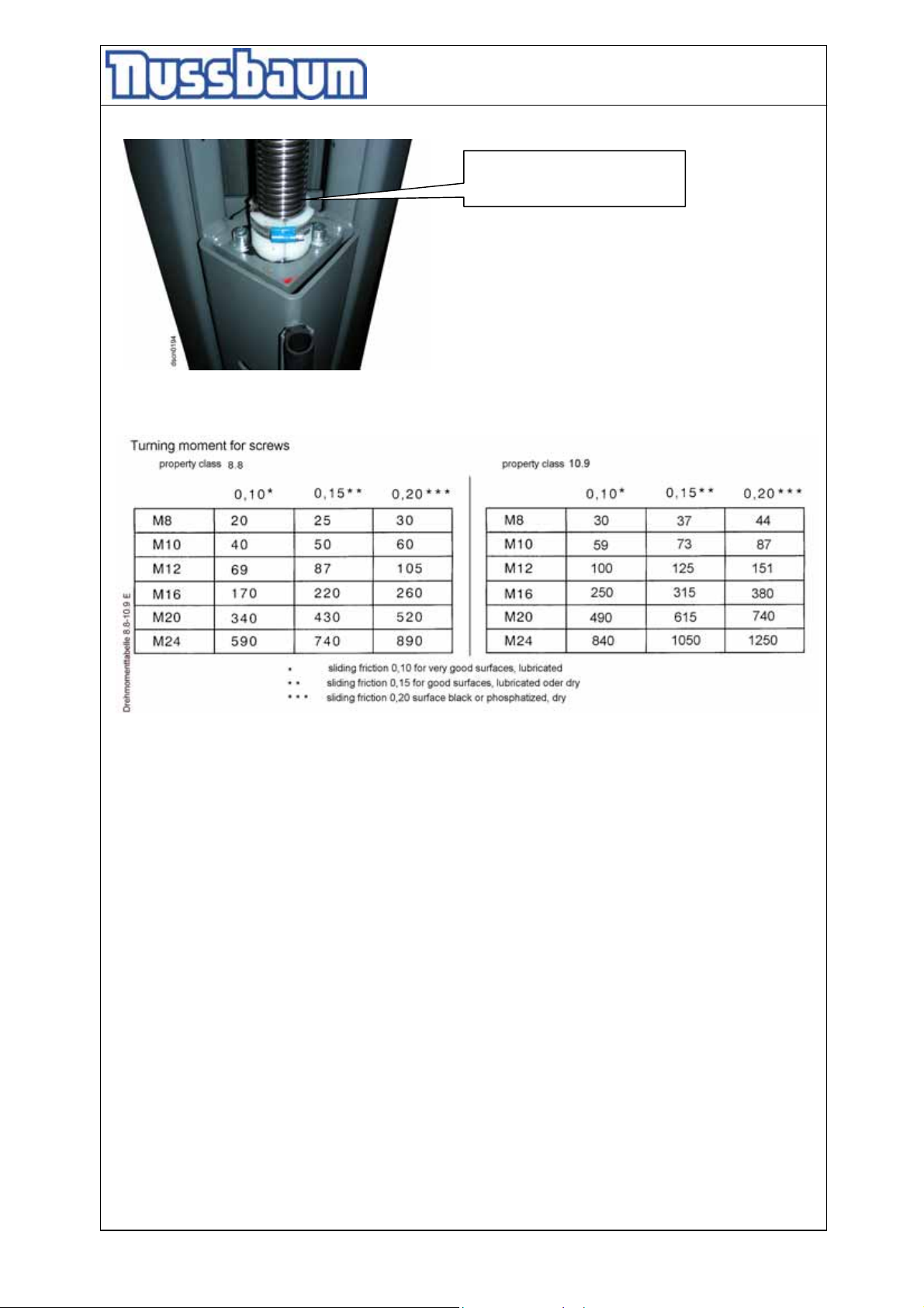
Pic 10: spindle centering
(after running, delay)
• Check that all screws and bolts are correctly torque (turning moments, see the list.
7.2 How often must the lift be cleaned?
A regular and appropriate maintenance practice will aid the preservation of the lift.
No guarantees can be given when damage (egg rust or fading colour) is the direct result of poor
maintenance and cleaning practice.
Regular cleaning of all kinds of dirt is the best protection against wear and the formation of rust
and will prolong the life of the lift
- Dirty deposits that can cause rust include:
• de-icing salt
• sand, pebble stone, natural soil
• all types of industrial dust
• water; also in connection with other environmental influences
• all types of aggressive deposits
• constant humidity caused by insufficient ventilation
Obviously this is dependent on the type of work being done with the lift, the degree of cleanliness
of the workshop and location of the lift. The degree and amount of dirt is dependent on the
season, on the weather conditions and the ventilation of the workshop.
During poor conditions it may be necessary to clean the lift once week, but cleaning once a
month will suffice.
- 46 -
Page 47
Operating Instruction and Documentation
4.50 SL
Clean the lift and the floor with a non-aggressive and non-abrasive detergent. Use a gentle
detergent to clean the parts. Use an standard washing-up liquid and lukewarm water.
- Do not use steam jet cleaners.
- Remove all dirt carefully with a sponge or if necessary with a brush.
- Ensure that no washing-up liquid is left on the lift after cleaning.
- Do not use aggressive means for cleaning the workshop floor and the automotive lift.
- A permanent contact with any kind of liquid is not allowed. Do not use high
pressure devices for cleaning the lift.
- After cleaning dry the automotive-lift with a suitable type of cloth and inject it with a wax spray
or an oil spray.
7.3 Adjust the Polylex-belt
If the V-belt was exchanged, the V-belt must be adjusted, again. Remove the cover of the V-belt.
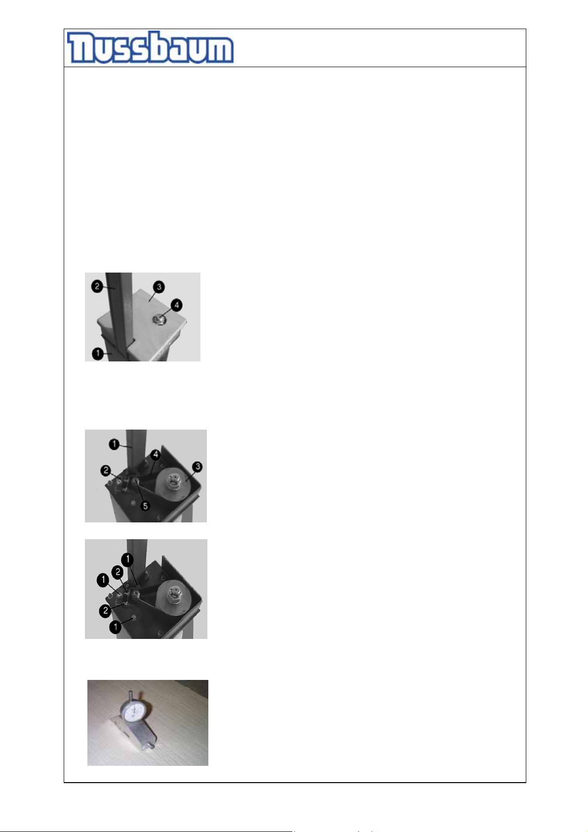
pic 10: cover of the belt (version with raising pipe)
1: column
2: raising pipe
3: cover of the belt
4: spindle
The new V-belt tension must be adjusted at the stretch device. (pic.11). Loose the three screws
at the motor easily. (pic. 11, No.1). The belt can be loosened or tightened at the screws. (pic.11,
No.2).
pic 11: position of the belt
1: raising pipe
2: stretch device
3: V-belt pulley
4: Polyflex-belt
5: shaft of the motor
pic 12: adjust the belt tension
1: the three screws of the motor
2: adjusting screws
The belt tension gets adjusted with the help of an accessory. (pic. 13; This accessory can be
ordered from Nußbaum).
pic 13: accessory
- 47 -
Page 48
Operating Instruction and Documentation
p
4.50 SL
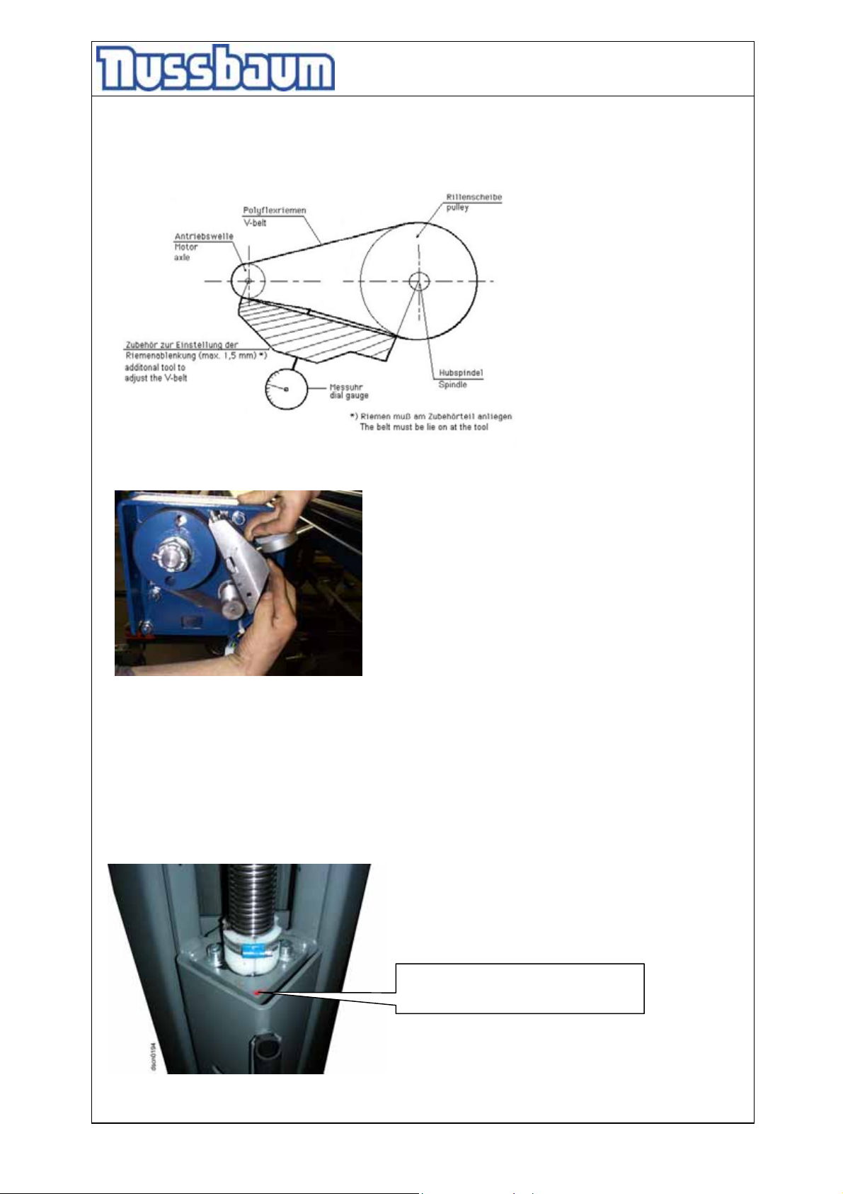
• Put the device on a solid flat surface. Push it down until the pin is on the flat surface. Position
the clock on zero. Turn the ring of the clock so long until the indicators are on zero. Put the
device on the V- belt (pic.14,15). The indicator of the clock may only turn mini. 1 (1mm) until
1,5 (1,5mm) turn.
pic14: measuring instrument
pic 15: Put the measuring device on the V-belt
• Bring the screws back in initial position.
7.4 Examine the carrying nut system
• Carrying nut (optical wearing device). To check the carrying nut, take off the covering of the
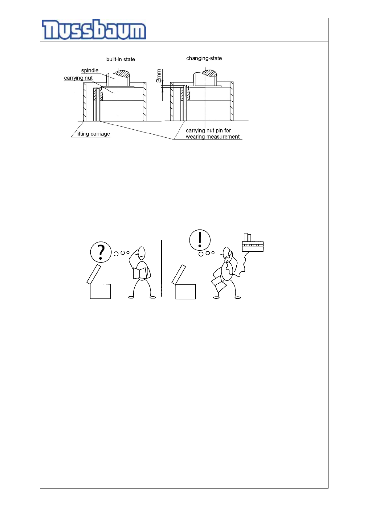
spindle (pic.3,pos.b). There is a pin built in the carrying plate (pic.16). This pin must be even
with the top edge of the carrying plate (upper side of the lifting carriage; built-in state pic.17). If
the pin looks 2 mm out of the top edge at the annually check (pic.17 changing state). The
carrying nut and the sequence nut must be replaced.
ic 16: the carrying-nut wear pin
marked with red safety colour
- 48 -
Page 49
Operating Instruction and Documentation
4.50 SL
pic 18: carrying nut
7.5 Examine of the stability of the automotive lift
• Examine the dowels with a torque key as described by the dowel manufacturer. Observe the
declaration of the dowel manufacturer.
8. Installation and Initiation
pic 18:
8.1 Regulations
• The installation of the lift is performed by trained technicians of the manufacturer or one of its
distribution partners. If the operator can provide trained mechanics, he or she can install the lift
by him or herself. The installation has to be done according to this regulation.
• Installing the standard-automotive lift in a hazardous location or a washing bay is not allowed.
• Before installation a sufficient foundation must be constructed. If the foundation is already
constructed then proof that the foundation conforms to the standard is required.
A level foundation for the installation is required. The foundations must be based in a frost
resistance depth, both outdoors and indoors in a position where the installer believes there is
no chance of frost.
• An standard electrical supply 3~/N+PE, 400 V, 50 Hz must be provided. Observe the electrical
power supply of your country.
The supply line must be protected with a time-lag fuse T32A (VDE0100 German regulation).
The minimum diameter amounts to 2.5 mm².
• All cable ducts must be equipped with protective coverings to prevent accidents.
• After assembly of the lift, the protective grounding of the lift must be examined after
International Electronical Commission (IEC) guidelines (60364-6-61) before first start-up by
operators. Also an insulation resistance examination is recommended.
- 49 -
Page 50
Operating Instruction and Documentation
4.50 SL
8.1.1 Erection and doweling of the lift
Before installation the lift, secure the installation area to prevent access to
unauthorised persons. Use devices such as cranes, fork lift trucks and supports to
transport the lift and avoid accidents.
Before installation of the lift create a sufficiently concrete by customer. The operator is
responsible for the installation place. A concrete with a quality of minimum C20/25 and a
thickness without tiles and floor pavement is necessary (thickness => see the foundation
drawing).
We point out the minimum requirement of the foundation in our plans. The condition of the local
realities (for example: the ground under the foundation) does not lie in our responsibility. The
execution of the installation situation must be individually specified by the planning architect or by
the engineer engaged in statically calculations in the special case.
In case of doubt a test boring has to be performed and a dowel is to set in. Afterwards the dowel
is tighten with a torque which is described of the dowel manufacturer.
If there are defectives (cracks or hairline cracks) in the zone of influence Ø200 mm, the
foundation cannot be used to install the lift on it.
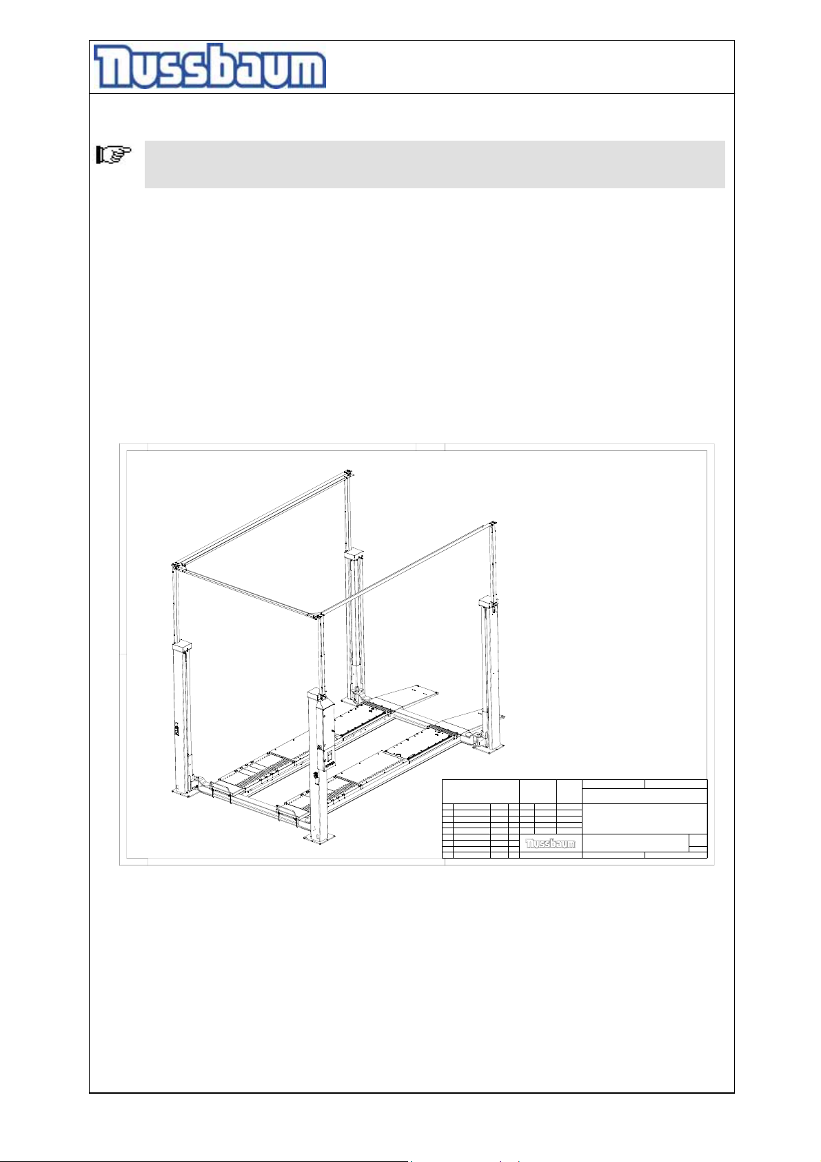
pic 19: complete automotive-lift
- 50 -
--
Nr
Aenderung
Masse ohne
Toleranzangaben
DIN ISO
2768 mH
Datum
Bearb.
24.04.12
Gepr.
Norm
Datum
Name
Urspr.
Massstab:
0.040
Werkstoff / Halbzeug
-;-
Name
Benennung
M.A
450SL BMW 4600/630
Zeichnungsnummer
450SL20015
Ersatz fuer:
Gewicht:
Ersatz durch:
3038.162
kg
Blatt
1
von
7
Page 51
Operating Instruction and Documentation
4.50 SL
A foundation must be constructed in accordance with the data sheet “foundation plan”. It must
be paid attention of an even installation place of the lift because of a straight contact between
lift and concrete floor.
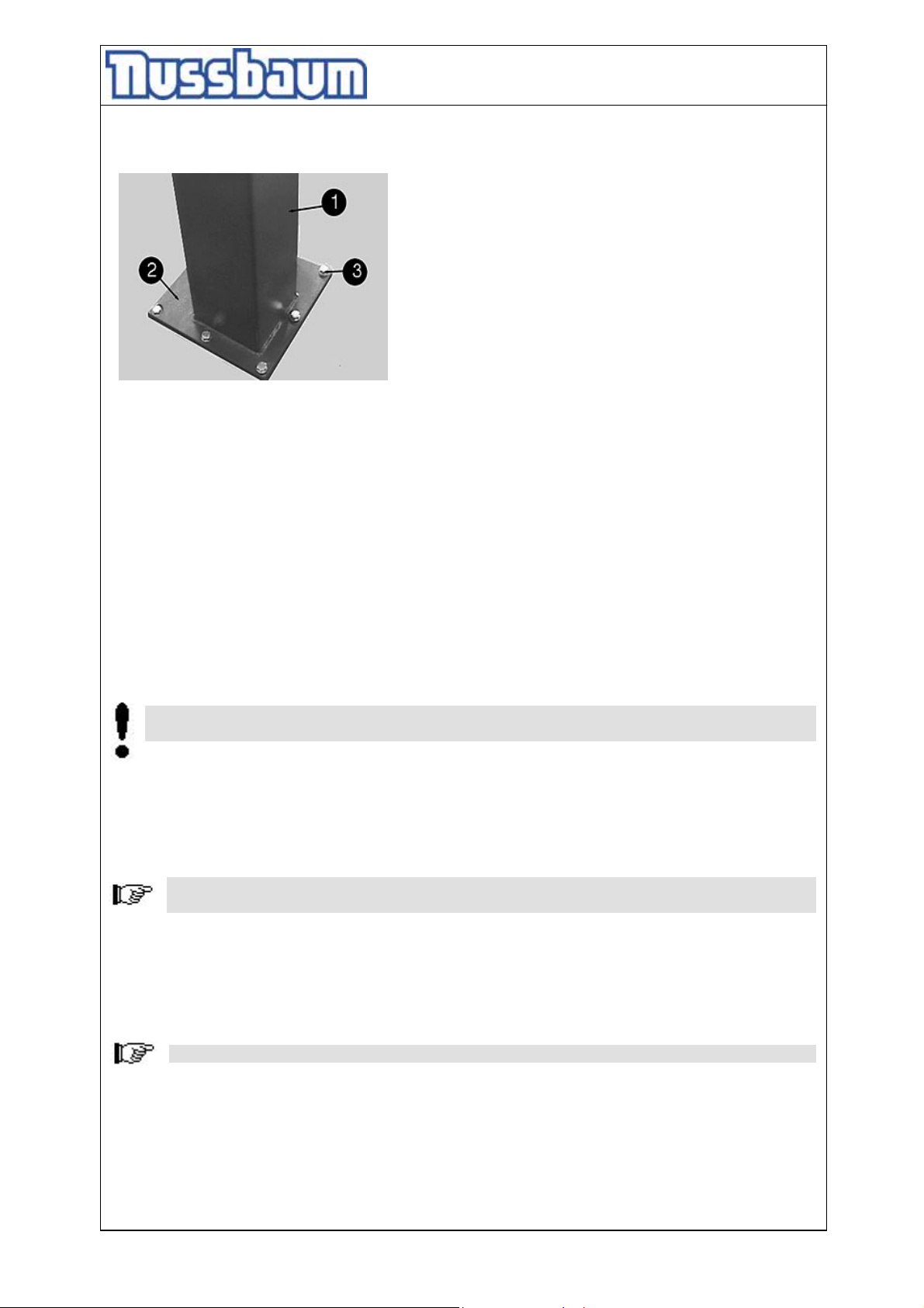
pic 20: dowel position
1: column
2: base plate
3: dowel
• Concrete has long chemical perspiration, which favour the corrosion at the base plates.
We recommended to provide the surface with a 2 components Epoxitharz floor coating,
before fastening the lift.
• Bore the holes to position the dowels through the bore holes of the base plates (pic.20).
Clean the holes with pressure air. Insert the dowels. The lift manufacturer demands e.g.
Liebig safety dowels or equal dowels of other manufacturer (with licence) but observe the
regulation. (bore hole, torque...).. Before doweling check the concrete floor with quality
C20/25(B25) if the concrete floor goes to the top edge of the floor. In this case the dowels
have to be chosen in according to the description (Dowels without tiles, floor pavement). If
the ground is covered with floor tiles, the dowels have to be chosen according to description
(Dowels with tiles, floor pavement). Observe the table of FISCHER Dowel manufacturer, too.
• Examine the lining up of the columns with spirit level.
• If necessary put thin metal sheets between the base plate and the floor until the lift is in the
correct vertical position and the contact between the base plate and the floor is available.
• Tighten the dowels with the dynamometric key. Observe the regulations of the dowel
manufacturer.
Each dowel must be tightened with the demanded torque. Otherwise the normal function
of the lift can not guaranteed.
• If the dowel is tightened with the demanded torque, the curved washer lies flat on the base
plate. A safe dowel connection is guaranteed.
8.2 Initiation
Before the initiation a security check must be carried out. Therefore use the form: First
security check.
If the lift is installed by a competent person, he or she is to perform the security check. If the
operator installs the lift by him or herself, he or she must instruct a competent person to
perform the security check.
The competent confirms the faultless function of the lift in the installation record and the form
for the security check and authorises the use of the lift.
Please send the completed installation record to the manufacturer after installation.
8.3 Change of lift location
If the place of installation shall be changed, the new place has to be prepared in according to
the regulations of the first installation. The changing should be performed in accordance with
the following points:
- 51 -
Page 52
Operating Instruction and Documentation
4.50 SL
• Lift or lower the carriage to medium height.
• Take away current supply from the lift.
• If necessary remove the ascending pipe and the traverse.
• Remove the cover of the lift.
• Disconnect the plugs.
• Loosen the dowels.
• Dismount the columns.
• Dismount the crossbeams.
• Transport the lift to the new installation place.
• Install the lift in accordance with chapter 8 “ Installation and Initiation”
Use new dowels, the used dowels can not be used anymore.
A security check must be performed before re initiation by a competent person. Use the sheet
“Regular security check”.
8.4 Key in the reference point with the keyboard
After mounting and adjusting of the lift and platforms, raise the lift on a comfortable working
height. (e.g. approx. 1250mm)
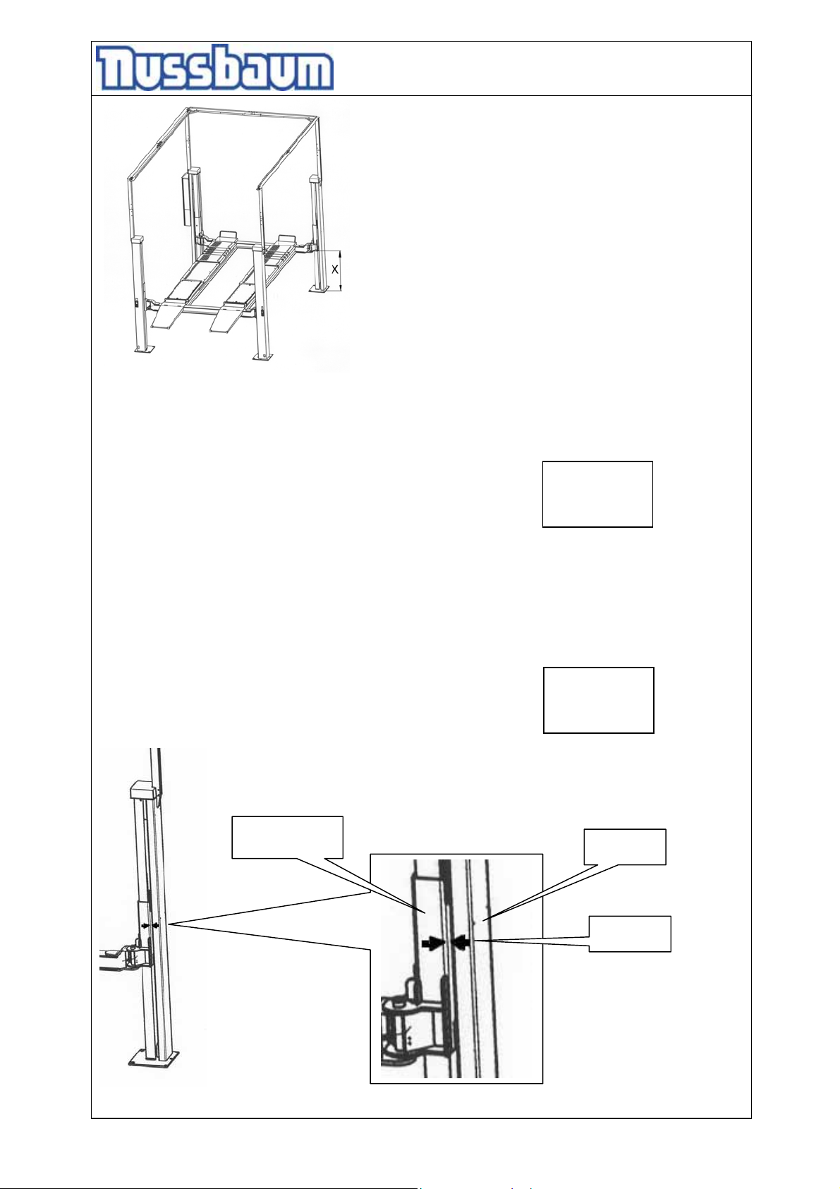
Position the arrow sticker at the lifting carriage and the column after entering of the new reference
point. (see the drawing)
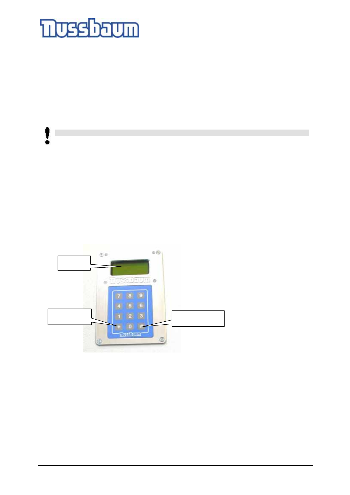
Display
star-button
Function button:
lozenge -button
<*> (star): back to the position display
> (lozenge): confirm button
<
#
• Measure the distance (X) between the lower edge of the lifting carriage and the upper side of the
base plate. Carry out the procedure at all four columns.
- 52 -
Page 53
Operating Instruction and Documentation
4.50 SL
• The smallest measure will be used later as the new reference point height.
Login to the service operation:
• (
#) Press it at the keyboard,
• Enter the numbers 1,2,3,4.
After the correct entering, it will be change into the main menu..
• Press the (*) button until to the Display shows „Referenzpunkt“.
• A menu item is selected with <>.
• Then press the button (#).The adjusted value will be displayed.
• Enter now the smallest 4-digit value in the keyboard. (e.g. 1237)
• Then press the button (#).The entered value is confirmed.
• Press the button (*) until the position display (start position).
• Before lifting or lowering the lift position the sticker.
Passwort
_ _ _ _
1 xxxx
2 xxxx
3 xxxx
4 xxxx
lifting carriage
- 53 -
column
arrow
Page 54
Operating Instruction and Documentation
4.50 SL
Unequal height after an lifting procedure „Referenzfahrt“
If you find after an lifting procedure a unequal position of one or more marker arrows, the unequal
height must be corrected manually.
Switch off the main switch before the different columns will be adjusted.
Remove the above cover of the affected column. Turn the spindle with a suitable tool until the
arrows are again on the same height. Repeat the procedure if necessary at the other columns.
Switch on the main switch if the adjusting is finished.
9. Security check
The security check is necessary to guarantee the safety of the lift during use. It has to be
performed in the following cases:
1. Before the initial operation, after the first installation.
Use the form “First security check before initiation”
2. In regular intervals after the initial operation, at least annually.
Use the form “Regular security check at least annually”
3. Every time the construction of that particular lift has been changed.
Use the form “Extraordinary security check”
The first and the regular security check must be performed by a competent person. It
is also recommended to carry out a service on the lift at this time.
After the construction of the lift has been changed (changing the lifting height or
capacity for example) and after serious maintenance works (welding load bearing
parts) an extraordinary security check must be performed by an expert.
This manual contains forms with a schedule for the security checks. Please us the appropriate
forms for the security checks. The forms should remain in this manual after they have been filled
out. A short description about special safety devices follows.
- 54 -
Page 55
Operating Instruction and Documentation
4.50 SL
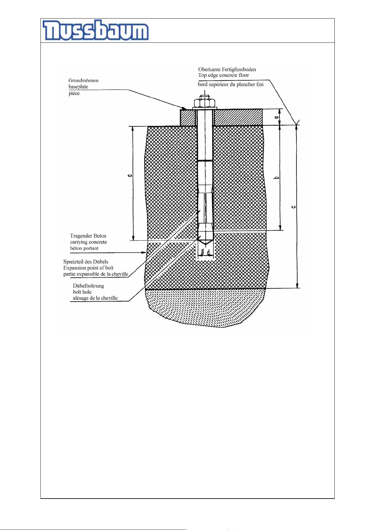
pic: Selection of Liebig-Dowels without tiles, floor pavement
Liebig dowels
Dowel typ BM12-20/80/40
Drilling depth a 100
Min. anchorage depth b 80
Thickness of concrete c min.160 (*)
Diameter of bore d 20
Thickness of the lift-pieces e 0-40
Quality of concrete min.C20/25 with normal armouring
Number of bolts according to the lift type
Starting torque 70 Nm
(*) minimum thickness of concrete by using the mentioned dowels. Otherwise,
observe the regulation of the foundation plan.
It is possible to use equivalent dowels from another dowel manufacturer (with license)
but observe their regulation.
- 55 -
Page 56
Operating Instruction and Documentation
4.50 SL
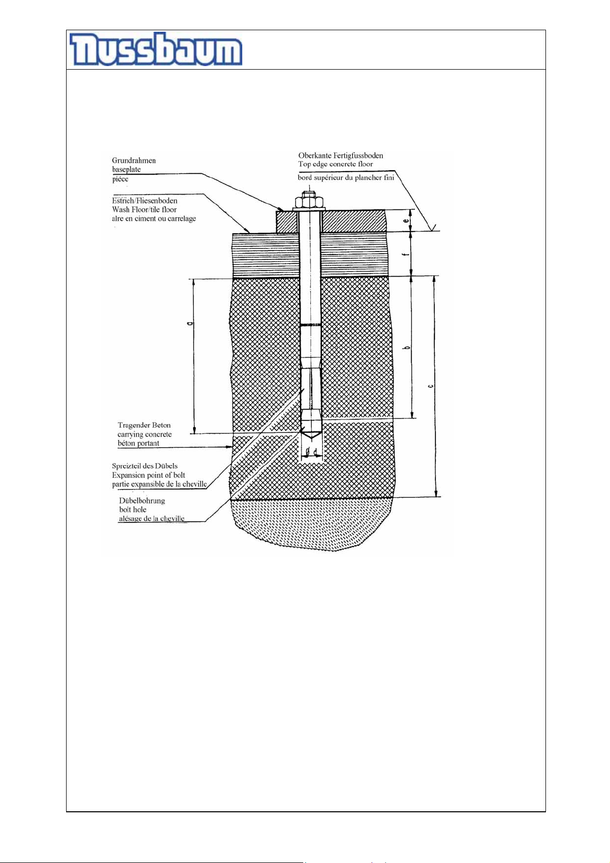
pic: Selection of Liebig-Dowels with tiles, floor pavement
Liebig dowels
Dowel type BM12-20/80/65 BM12-20/80/100 BM12-20/80/140
Drilling depth (mm) a 100 100 100
Min. anchorage depth (mm) b 80 80 80
Thickness of concrete (mm) c min.160(*) min.160(*) min.160(*)
Diameter of bore (mm) d 20 20 20
Thickness of the lift-pieces (mm) e+f 40-65 65-100 100-140
Quality of concrete min.C20/25 with normal armouring
Number of bolts according to the lift type
Starting torque 70 Nm 70Nm 70Nm
(*) minimum thickness of concrete by using the mentioned dowels. Otherwise,
observe the regulation of the foundation plan.
It is possible to use equivalent dowels from another dowel manufacturer (with license) but
observe their regulation.
- 56 -
Page 57
Operating Instruction and Documentation
Ä
4.50 SL
nderungen vorbehalten!
subject to alterations!
sous réserve des modifications!
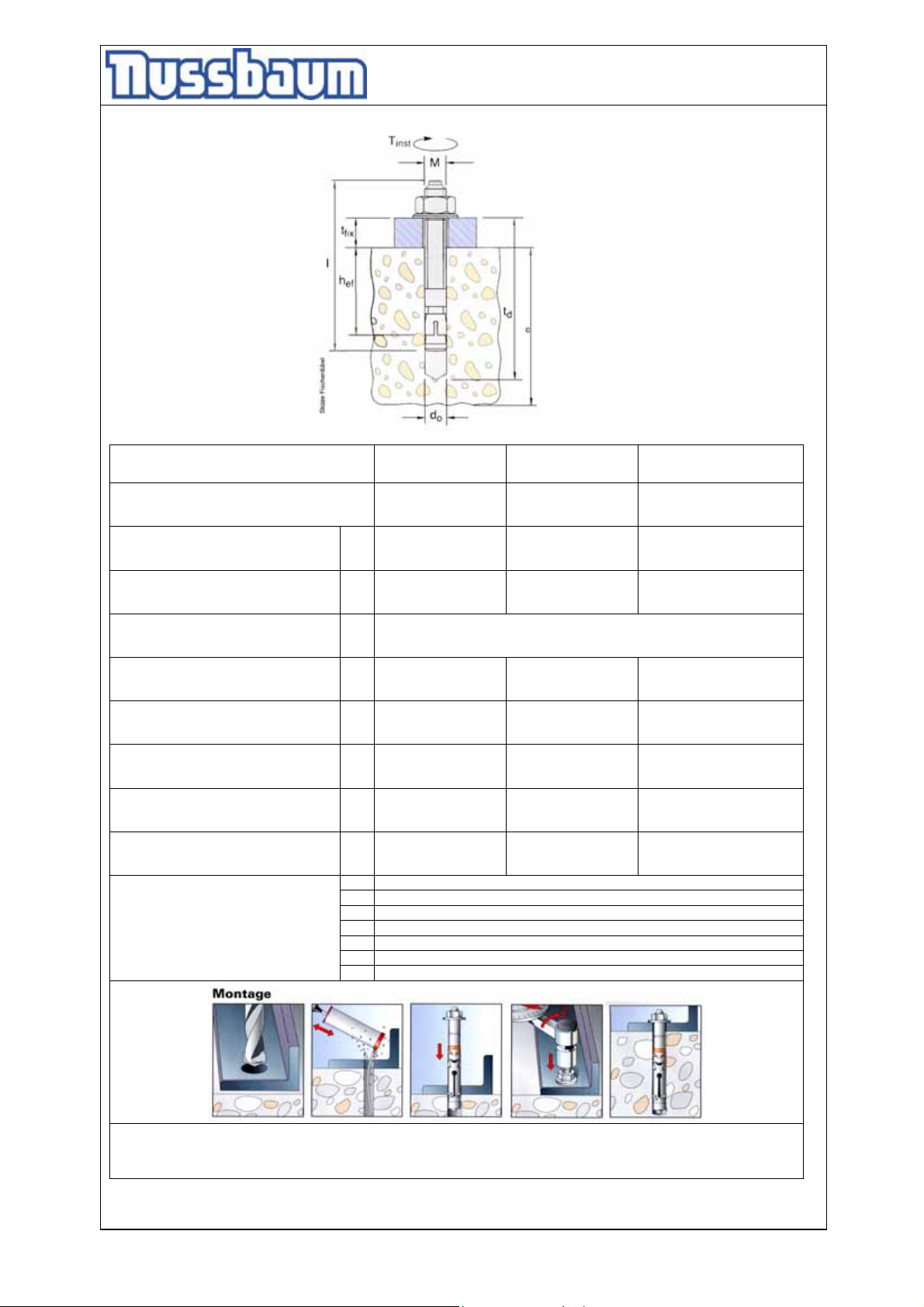
fischer-dowel
Dübel
typ of dowel
type de cheville
Bohrteife
drilling depth
Profondeur de l’alésage
Mindestverankerungstiefe
min.anchorage depth
Profondeur minimale dáncrage
Betonstärke
thickness of concrete
Epaisseur du béton
Bohrerdurchmesser
diameter of bore
Diamètre de l’alésage
Bauteildicke
thickness of the lift-piece
Epaisseur de la pièce
Anzugsdrehmoment Nm
turníng moment
moment d´une force
Gesamtlänge
Total length
Longueur totale
Gewinde
Thread
fil
Stückzahl
piece number
nombre des pièces
FH 15/50 B
Bestellnr. 970265
td 145 230 255
hef 70 100 125
c
do 15 18 24
tfix 0-50 0-100 0-100
MD 40 80 120
l 155 230 272
M M10 M12 M16
a
b
c
d
e
f
g
4.50 SL
f
FH 18 x 100/100 B
Bestellnr: 972230
siehe den aktuellen Fundamentplan
see current foundation-diagram drawing
vois le plan de fondation actuel
4
8
10
12
16
24
14
FH 24/100 B
Bestellnr. 970267
Es können auch gleichwertige Sicherheitsdübel anderer Hersteller (mit Zulassung) unter Beachtung deren Bestimmungen verwendet werden.
It is possible to use equivalent safety-dowels (with license) of other manufacturer but observe their regulations.
Des chevilles des autres marques (autorisées) peuvent aussi être choisies en respetant les directives du fabricant.
- 57 -
Page 58
Operating Instruction and Documentation
4.50 SL
First security check before installation
Fill out and leave in this manual Serial-number:__________________________
all defect veri-
kind of check right missing fication remark
--------------------------------------------------------------------------------------------------------------------------------------
Type plate.........................................…….......... F F F ...............................................
short operating instruction at the column............ F F F ...............................................
sticker capacity at the column............................ F F F ...............................................
sticker lubrication/maintenance plan................... F F F ...............................................
Detailed operating instruction.......……............... F F F ...............................................
Condition Automotive-lift.................................... F F F ...............................................
Designation „lifting/lowering“............................. F F F ...............................................
Function button „lifting/lowering“......................... F F F ...............................................
Function button „equalisation“.…....................... F F F ...............................................
Condition, Function Display…..…....................... F F F ...............................................
Condition, Electrical box….…...…....................... F F F ...............................................
Condition, Function main switch..……..............
Safety seeger ring at the bolts (carriage)........... F F F ...............................................
Function CE-Stop + acoustic signal ………...... F F F ...............................................
Condition bolts and DU-bearings........................ F F F ...............................................
Condition Platform.........………………............... F F F ...............................................
Condition, Function drive on ramps……............ F F F ...............................................
Condition colour................................................. F F F ...............................................
Condition Construction (deformation, cracking).. F F F ...............................................
Torque moment of screws and dowels ……....... F F F ...............................................
Condition Poly V-Belt…...................................... F F F ...............................................
Condition, Function spindle centering.................. F F F ...............................................
Condition Crossbeam & cable channel............... F F F ...............................................
Condition of the covers ……............................. F F F ...............................................
Condition Spindle and carrying nut.................... F F F ...............................................
Condition carrying nut wear pin………................ F F F ...............................................
Condition concrete (cracking)............................. F F F ...............................................
Condition electrical cables and plugs................. F F F ...............................................
Function lighting…………................................... F F F ...............................................
Function test with vehicle................................... F F F ...............................................
Function test „driving to the end position “........... F F F ...............................................
Function equalisation of the lift............................ F F F ...............................................
( mark here applicable, in case of verification mark in addition to the first mark!)
F F F ...............................................
Security check carried out:.............................................................................................…………….........................
Carried out the company:.............................................................................…………………...................................
Name, address of the competent:.....................................................................……………............……..................
Result of the Check:
F Initiation not permitted, verification necessary
F Initiation possible, repair failures until.........................................................
F No failings, Initiation possible
........................................................ ...........................................................
signature of the expert signature of the operator
If failures must be repaired:
Failures repaired at: .......................... ..................................................
signature of the operator
(Use another form for verification!)
- 58 -
Page 59
Operating Instruction and Documentation
4.50 SL
Regular security check and maintenance
Fill out and leave in this manual Serial-number:__________________________
all defect veri-
kind of check right missing fication remark
--------------------------------------------------------------------------------------------------------------------------------------
Type plate.........................................…….......... F F F ...............................................
short operating instruction at the column............ F F F ...............................................
sticker capacity at the column............................ F F F ...............................................
sticker lubrication/maintenance plan................... F F F ...............................................
Detailed operating instruction.......……............... F F F ...............................................
Condition Automotive-lift.................................... F F F ...............................................
Designation „lifting/lowering“............................. F F F ...............................................
Function button „lifting/lowering“......................... F F F ...............................................
Function button „equalisation“.…....................... F F F ...............................................
Condition, Function Display…..…....................... F F F ...............................................
Condition, Electrical box….…...…....................... F F F ...............................................
Condition, Function main switch..……..............
Safety seeger ring at the bolts (carriage)........... F F F ...............................................
Function CE-Stop + acoustic signal ………...... F F F ...............................................
Condition bolts and DU-bearings........................ F F F ...............................................
Condition Platform.........………………............... F F F ...............................................
Condition, Function drive on ramps……............ F F F ...............................................
Condition colour................................................. F F F ...............................................
Condition Construction (deformation, cracking).. F F F ...............................................
Torque moment of screws and dowels ……....... F F F ...............................................
Condition Poly V-Belt…...................................... F F F ...............................................
Condition, Function spindle centering.................. F F F ...............................................
Condition Crossbeam & cable channel............... F F F ...............................................
Condition of the covers …….............................
Condition Spindle and carrying nut.................... F F F ...............................................
Condition carrying nut wear pin………................ F F F ...............................................
Condition concrete (cracking)............................. F F F ...............................................
Condition electrical cables and plugs................. F F F ...............................................
Function lighting…………................................... F F F ...............................................
Function test with vehicle................................... F F F ...............................................
Function test „driving to the end position “........... F F F ...............................................
Function equalisation of the lift............................ F F F ...............................................
( mark here applicable, in case of verification mark in addition to the first mark!)
F F F ...............................................
F F F ...............................................
Security check carried out:.............................................................................................…………….........................
Carried out the company:.............................................................................…………………...................................
Name, address of the competent:.....................................................................……………............……..................
Result of the Check:
F Initiation not permitted, verification necessary
F Initiation possible, repair failures until.........................................................
F No failings, Initiation possible
........................................................ ...........................................................
signature of the expert signature of the operator
If failures must be repaired:
Failures repaired at: .......................... ..................................................
signature of the operator
(Use another form for verification!)
- 59 -
Page 60
Operating Instruction and Documentation
4.50 SL
Regular security check and maintenance
Fill out and leave in this manual Serial-number:__________________________
all defect veri-
kind of check right missing fication remark
--------------------------------------------------------------------------------------------------------------------------------------
Type plate.........................................…….......... F F F ...............................................
short operating instruction at the column............ F F F ...............................................
sticker capacity at the column............................ F F F ...............................................
sticker lubrication/maintenance plan................... F F F ...............................................
Detailed operating instruction.......……............... F F F ...............................................
Condition Automotive-lift.................................... F F F ...............................................
Designation „lifting/lowering“............................. F F F ...............................................
Function button „lifting/lowering“......................... F F F ...............................................
Function button „equalisation“.…....................... F F F ...............................................
Condition, Function Display…..…....................... F F F ...............................................
Condition, Electrical box….…...…....................... F F F ...............................................
Condition, Function main switch..……..............
Safety seeger ring at the bolts (carriage)........... F F F ...............................................
Function CE-Stop + acoustic signal ………...... F F F ...............................................
Condition bolts and DU-bearings........................ F F F ...............................................
Condition Platform.........………………............... F F F ...............................................
Condition, Function drive on ramps……............ F F F ...............................................
Condition colour................................................. F F F ...............................................
Condition Construction (deformation, cracking).. F F F ...............................................
Torque moment of screws and dowels ……....... F F F ...............................................
Condition Poly V-Belt…...................................... F F F ...............................................
Condition, Function spindle centering.................. F F F ...............................................
Condition Crossbeam & cable channel............... F F F ...............................................
Condition of the covers …….............................
Condition Spindle and carrying nut.................... F F F ...............................................
Condition carrying nut wear pin………................ F F F ...............................................
Condition concrete (cracking)............................. F F F ...............................................
Condition electrical cables and plugs................. F F F ...............................................
Function lighting…………................................... F F F ...............................................
Function test with vehicle................................... F F F ...............................................
Function test „driving to the end position “........... F F F ...............................................
Function equalisation of the lift............................ F F F ...............................................
( mark here applicable, in case of verification mark in addition to the first mark!)
F F F ...............................................
F F F ...............................................
Security check carried out:.............................................................................................…………….........................
Carried out the company:.............................................................................…………………...................................
Name, address of the competent:.....................................................................……………............……..................
Result of the Check:
F Initiation not permitted, verification necessary
F Initiation possible, repair failures until.........................................................
F No failings, Initiation possible
........................................................ ...........................................................
signature of the expert signature of the operator
If failures must be repaired:
Failures repaired at: .......................... ..................................................
signature of the operator
(Use another form for verification!)
- 60 -
Page 61
Operating Instruction and Documentation
4.50 SL
Regular security check and maintenance
Fill out and leave in this manual Serial-number:__________________________
all defect veri-
kind of check right missing fication remark
--------------------------------------------------------------------------------------------------------------------------------------
Type plate.........................................…….......... F F F ...............................................
short operating instruction at the column............ F F F ...............................................
sticker capacity at the column............................ F F F ...............................................
sticker lubrication/maintenance plan................... F F F ...............................................
Detailed operating instruction.......……............... F F F ...............................................
Condition Automotive-lift.................................... F F F ...............................................
Designation „lifting/lowering“............................. F F F ...............................................
Function button „lifting/lowering“......................... F F F ...............................................
Function button „equalisation“.…....................... F F F ...............................................
Condition, Function Display…..…....................... F F F ...............................................
Condition, Electrical box….…...…....................... F F F ...............................................
Condition, Function main switch..……..............
Safety seeger ring at the bolts (carriage)........... F F F ...............................................
Function CE-Stop + acoustic signal ………...... F F F ...............................................
Condition bolts and DU-bearings........................ F F F ...............................................
Condition Platform.........………………............... F F F ...............................................
Condition, Function drive on ramps……............ F F F ...............................................
Condition colour................................................. F F F ...............................................
Condition Construction (deformation, cracking).. F F F ...............................................
Torque moment of screws and dowels ……....... F F F ...............................................
Condition Poly V-Belt…...................................... F F F ...............................................
Condition, Function spindle centering.................. F F F ...............................................
Condition Crossbeam & cable channel............... F F F ...............................................
Condition of the covers …….............................
Condition Spindle and carrying nut.................... F F F ...............................................
Condition carrying nut wear pin………................ F F F ...............................................
Condition concrete (cracking)............................. F F F ...............................................
Condition electrical cables and plugs................. F F F ...............................................
Function lighting…………................................... F F F ...............................................
Function test with vehicle................................... F F F ...............................................
Function test „driving to the end position “........... F F F ...............................................
Function equalisation of the lift............................ F F F ...............................................
( mark here applicable, in case of verification mark in addition to the first mark!)
F F F ...............................................
F F F ...............................................
Security check carried out:.............................................................................................…………….........................
Carried out the company:.............................................................................…………………...................................
Name, address of the competent:.....................................................................……………............……..................
Result of the Check:
F Initiation not permitted, verification necessary
F Initiation possible, repair failures until.........................................................
F No failings, Initiation possible
........................................................ ...........................................................
signature of the expert signature of the operator
If failures must be repaired:
Failures repaired at: .......................... ..................................................
signature of the operator
(Use another form for verification!)
- 61 -
Page 62
Operating Instruction and Documentation
4.50 SL
Regular security check and maintenance
Fill out and leave in this manual Serial-number:__________________________
all defect veri-
kind of check right missing fication remark
--------------------------------------------------------------------------------------------------------------------------------------
Type plate.........................................…….......... F F F ...............................................
short operating instruction at the column............ F F F ...............................................
sticker capacity at the column............................ F F F ...............................................
sticker lubrication/maintenance plan................... F F F ...............................................
Detailed operating instruction.......……............... F F F ...............................................
Condition Automotive-lift.................................... F F F ...............................................
Designation „lifting/lowering“............................. F F F ...............................................
Function button „lifting/lowering“......................... F F F ...............................................
Function button „equalisation“.…....................... F F F ...............................................
Condition, Function Display…..…....................... F F F ...............................................
Condition, Electrical box….…...…....................... F F F ...............................................
Condition, Function main switch..……..............
Safety seeger ring at the bolts (carriage)........... F F F ...............................................
Function CE-Stop + acoustic signal ………...... F F F ...............................................
Condition bolts and DU-bearings........................ F F F ...............................................
Condition Platform.........………………............... F F F ...............................................
Condition, Function drive on ramps……............ F F F ...............................................
Condition colour................................................. F F F ...............................................
Condition Construction (deformation, cracking).. F F F ...............................................
Torque moment of screws and dowels ……....... F F F ...............................................
Condition Poly V-Belt…...................................... F F F ...............................................
Condition, Function spindle centering.................. F F F ...............................................
Condition Crossbeam & cable channel............... F F F ...............................................
Condition of the covers …….............................
Condition Spindle and carrying nut.................... F F F ...............................................
Condition carrying nut wear pin………................ F F F ...............................................
Condition concrete (cracking)............................. F F F ...............................................
Condition electrical cables and plugs................. F F F ...............................................
Function test with vehicle................................... F F F ...............................................
Function test „driving to the end position “........... F F F ...............................................
Function equalisation of the lift............................ F F F ...............................................
( mark here applicable, in case of verification mark in addition to the first mark!)
F F F ...............................................
F F F ...............................................
Security check carried out:.............................................................................................…………….........................
Carried out the company:.............................................................................…………………...................................
Name, address of the competent:.....................................................................……………............……..................
Result of the Check:
F Initiation not permitted, verification necessary
F Initiation possible, repair failures until.........................................................
F No failings, Initiation possible
........................................................ ...........................................................
signature of the expert signature of the operator
If failures must be repaired:
Failures repaired at: .......................... ..................................................
signature of the operator
(Use another form for verification!)
- 62 -
Page 63
Operating Instruction and Documentation
4.50 SL
Regular security check and maintenance
Fill out and leave in this manual Serial-number:__________________________
all defect veri-
kind of check right missing fication remark
--------------------------------------------------------------------------------------------------------------------------------------
Type plate.........................................…….......... F F F ...............................................
short operating instruction at the column............ F F F ...............................................
sticker capacity at the column............................ F F F ...............................................
sticker lubrication/maintenance plan................... F F F ...............................................
Detailed operating instruction.......……............... F F F ...............................................
Condition Automotive-lift.................................... F F F ...............................................
Designation „lifting/lowering“............................. F F F ...............................................
Function button „lifting/lowering“......................... F F F ...............................................
Function button „equalisation“.…....................... F F F ...............................................
Condition, Function Display…..…....................... F F F ...............................................
Condition, Electrical box….…...…....................... F F F ...............................................
Condition, Function main switch..……..............
Safety seeger ring at the bolts (carriage)........... F F F ...............................................
Function CE-Stop + acoustic signal ………...... F F F ...............................................
Condition bolts and DU-bearings........................ F F F ...............................................
Condition Platform.........………………............... F F F ...............................................
Condition, Function drive on ramps……............ F F F ...............................................
Condition colour................................................. F F F ...............................................
Condition Construction (deformation, cracking).. F F F ...............................................
Torque moment of screws and dowels ……....... F F F ...............................................
Condition Poly V-Belt…...................................... F F F ...............................................
Condition, Function spindle centering.................. F F F ...............................................
Condition Crossbeam & cable channel............... F F F ...............................................
Condition of the covers …….............................
Condition Spindle and carrying nut.................... F F F ...............................................
Condition carrying nut wear pin………................ F F F ...............................................
Condition concrete (cracking)............................. F F F ...............................................
Condition electrical cables and plugs................. F F F ...............................................
Function lighting…………................................... F F F ...............................................
Function test with vehicle................................... F F F ...............................................
Function test „driving to the end position “........... F F F ...............................................
Function equalisation of the lift............................ F F F ...............................................
( mark here applicable, in case of verification mark in addition to the first mark!)
F F F ...............................................
F F F ...............................................
Security check carried out:.............................................................................................…………….........................
Carried out the company:.............................................................................…………………...................................
Name, address of the competent:.....................................................................……………............……..................
Result of the Check:
F Initiation not permitted, verification necessary
F Initiation possible, repair failures until.........................................................
F No failings, Initiation possible
........................................................ ...........................................................
signature of the expert signature of the operator
If failures must be repaired:
Failures repaired at: .......................... ..................................................
signature of the operator
(Use another form for verification!)
- 63 -
Page 64
Operating Instruction and Documentation
4.50 SL
Regular security check and maintenance
Fill out and leave in this manual Serial-number:__________________________
all defect veri-
kind of check right missing fication remark
--------------------------------------------------------------------------------------------------------------------------------------
Type plate.........................................…….......... F F F ...............................................
short operating instruction at the column............ F F F ...............................................
sticker capacity at the column............................ F F F ...............................................
sticker lubrication/maintenance plan................... F F F ...............................................
Detailed operating instruction.......……............... F F F ...............................................
Condition Automotive-lift.................................... F F F ...............................................
Designation „lifting/lowering“............................. F F F ...............................................
Function button „lifting/lowering“......................... F F F ...............................................
Function button „equalisation“.…....................... F F F ...............................................
Condition, Function Display…..…....................... F F F ...............................................
Condition, Electrical box….…...…....................... F F F ...............................................
Condition, Function main switch..……..............
Safety seeger ring at the bolts (carriage)........... F F F ...............................................
Function CE-Stop + acoustic signal ………...... F F F ...............................................
Condition bolts and DU-bearings........................ F F F ...............................................
Condition Platform.........………………............... F F F ...............................................
Condition, Function drive on ramps……............ F F F ...............................................
Condition colour................................................. F F F ...............................................
Condition Construction (deformation, cracking).. F F F ...............................................
Torque moment of screws and dowels ……....... F F F ...............................................
Condition Poly V-Belt…...................................... F F F ...............................................
Condition, Function spindle centering.................. F F F ...............................................
Condition Crossbeam & cable channel............... F F F ...............................................
Condition of the covers …….............................
Condition Spindle and carrying nut.................... F F F ...............................................
Condition carrying nut wear pin………................ F F F ...............................................
Condition concrete (cracking)............................. F F F ...............................................
Condition electrical cables and plugs................. F F F ...............................................
Function lighting…………................................... F F F ...............................................
Function test with vehicle................................... F F F ...............................................
Function test „driving to the end position “........... F F F ...............................................
Function equalisation of the lift............................ F F F ...............................................
( mark here applicable, in case of verification mark in addition to the first mark!)
F F F ...............................................
F F F ...............................................
Security check carried out:.............................................................................................…………….........................
Carried out the company:.............................................................................…………………...................................
Name, address of the competent:.....................................................................……………............……..................
Result of the Check:
F Initiation not permitted, verification necessary
F Initiation possible, repair failures until.........................................................
F No failings, Initiation possible
........................................................ ...........................................................
signature of the expert signature of the operator
If failures must be repaired:
Failures repaired at: .......................... ..................................................
signature of the operator
(Use another form for verification!)
- 64 -
Page 65
Operating Instruction and Documentation
4.50 SL
Regular security check and maintenance
Fill out and leave in this manual Serial-number:__________________________
all defect veri-
kind of check right missing fication remark
--------------------------------------------------------------------------------------------------------------------------------------
Type plate.........................................…….......... F F F ...............................................
short operating instruction at the column............ F F F ...............................................
sticker capacity at the column............................ F F F ...............................................
sticker lubrication/maintenance plan................... F F F ...............................................
Detailed operating instruction.......……............... F F F ...............................................
Condition Automotive-lift.................................... F F F ...............................................
Designation „lifting/lowering“............................. F F F ...............................................
Function button „lifting/lowering“......................... F F F ...............................................
Function button „equalisation“.…....................... F F F ...............................................
Condition, Function Display…..…....................... F F F ...............................................
Condition, Electrical box….…...…....................... F F F ...............................................
Condition, Function main switch..……..............
Safety seeger ring at the bolts (carriage)........... F F F ...............................................
Function CE-Stop + acoustic signal ………...... F F F ...............................................
Condition bolts and DU-bearings........................ F F F ...............................................
Condition Platform.........………………............... F F F ...............................................
Condition, Function drive on ramps……............ F F F ...............................................
Condition colour................................................. F F F ...............................................
Condition Construction (deformation, cracking).. F F F ...............................................
Torque moment of screws and dowels ……....... F F F ...............................................
Condition Poly V-Belt…...................................... F F F ...............................................
Condition, Function spindle centering.................. F F F ...............................................
Condition Crossbeam & cable channel............... F F F ...............................................
Condition of the covers …….............................
Condition Spindle and carrying nut.................... F F F ...............................................
Condition carrying nut wear pin………................ F F F ...............................................
Condition concrete (cracking)............................. F F F ...............................................
Condition electrical cables and plugs................. F F F ...............................................
Function lighting…………................................... F F F ...............................................
Function test with vehicle................................... F F F ...............................................
Function test „driving to the end position “........... F F F ...............................................
Function equalisation of the lift............................ F F F ...............................................
( mark here applicable, in case of verification mark in addition to the first mark!)
F F F ...............................................
F F F ...............................................
Security check carried out:.............................................................................................…………….........................
Carried out the company:.............................................................................…………………...................................
Name, address of the competent:.....................................................................……………............……..................
Result of the Check:
F Initiation not permitted, verification necessary
F Initiation possible, repair failures until.........................................................
F No failings, Initiation possible
........................................................ ...........................................................
signature of the expert signature of the operator
If failures must be repaired:
Failures repaired at: .......................... ..................................................
signature of the operator
(Use another form for verification!)
- 65 -
Page 66
Operating Instruction and Documentation
4.50 SL
Extraordinary security check
Fill out and leave in this manual Serial-number:__________________________
all defect veri-
kind of check right missing fication remark
--------------------------------------------------------------------------------------------------------------------------------------
Type plate.........................................…….......... F F F ...............................................
short operating instruction at the column............ F F F ...............................................
sticker capacity at the column............................ F F F ...............................................
sticker lubrication/maintenance plan................... F F F ...............................................
Detailed operating instruction.......……............... F F F ...............................................
Condition Automotive-lift.................................... F F F ...............................................
Designation „lifting/lowering“............................. F F F ...............................................
Function button „lifting/lowering“......................... F F F ...............................................
Function button „equalisation“.…....................... F F F ...............................................
Condition, Function Display…..…....................... F F F ...............................................
Condition, Electrical box….…...…....................... F F F ...............................................
Condition, Function main switch..……..............
Safety seeger ring at the bolts (carriage)........... F F F ...............................................
Function CE-Stop + acoustic signal ………...... F F F ...............................................
Condition bolts and DU-bearings........................ F F F ...............................................
Condition Platform.........………………............... F F F ...............................................
Condition, Function drive on ramps……............ F F F ...............................................
Condition colour................................................. F F F ...............................................
Condition Construction (deformation, cracking).. F F F ...............................................
Torque moment of screws and dowels ……....... F F F ...............................................
Condition Poly V-Belt…...................................... F F F ...............................................
Condition, Function spindle centering.................. F F F ...............................................
Condition Crossbeam & cable channel............... F F F ...............................................
Condition of the covers …….............................
Condition Spindle and carrying nut.................... F F F ...............................................
Condition carrying nut wear pin………................ F F F ...............................................
Condition concrete (cracking)............................. F F F ...............................................
Condition electrical cables and plugs................. F F F ...............................................
Function lighting…………................................... F F F ...............................................
Function test with vehicle................................... F F F ...............................................
Function test „driving to the end position “........... F F F ...............................................
Function equalisation of the lift............................ F F F ...............................................
( mark here applicable, in case of verification mark in addition to the first mark!)
F F F ...............................................
F F F ...............................................
Security check carried out:.............................................................................................…………….........................
Carried out the company:.............................................................................…………………...................................
Name, address of the competent:.....................................................................……………............……..................
Result of the Check:
F Initiation not permitted, verification necessary
F Initiation possible, repair failures until.........................................................
F No failings, Initiation possible
........................................................ ...........................................................
signature of the expert signature of the operator
If failures must be repaired:
Failures repaired at: .......................... ..................................................
signature of the operator
(Use another form for verification!)
- 66 -
 Loading...