

Nussbaum 4.250 H SST, 4.200 H SST, 4.80 H SST, 4.300 H SST, 4.120 H SST Operating Instruction And Documentation
...Page 1
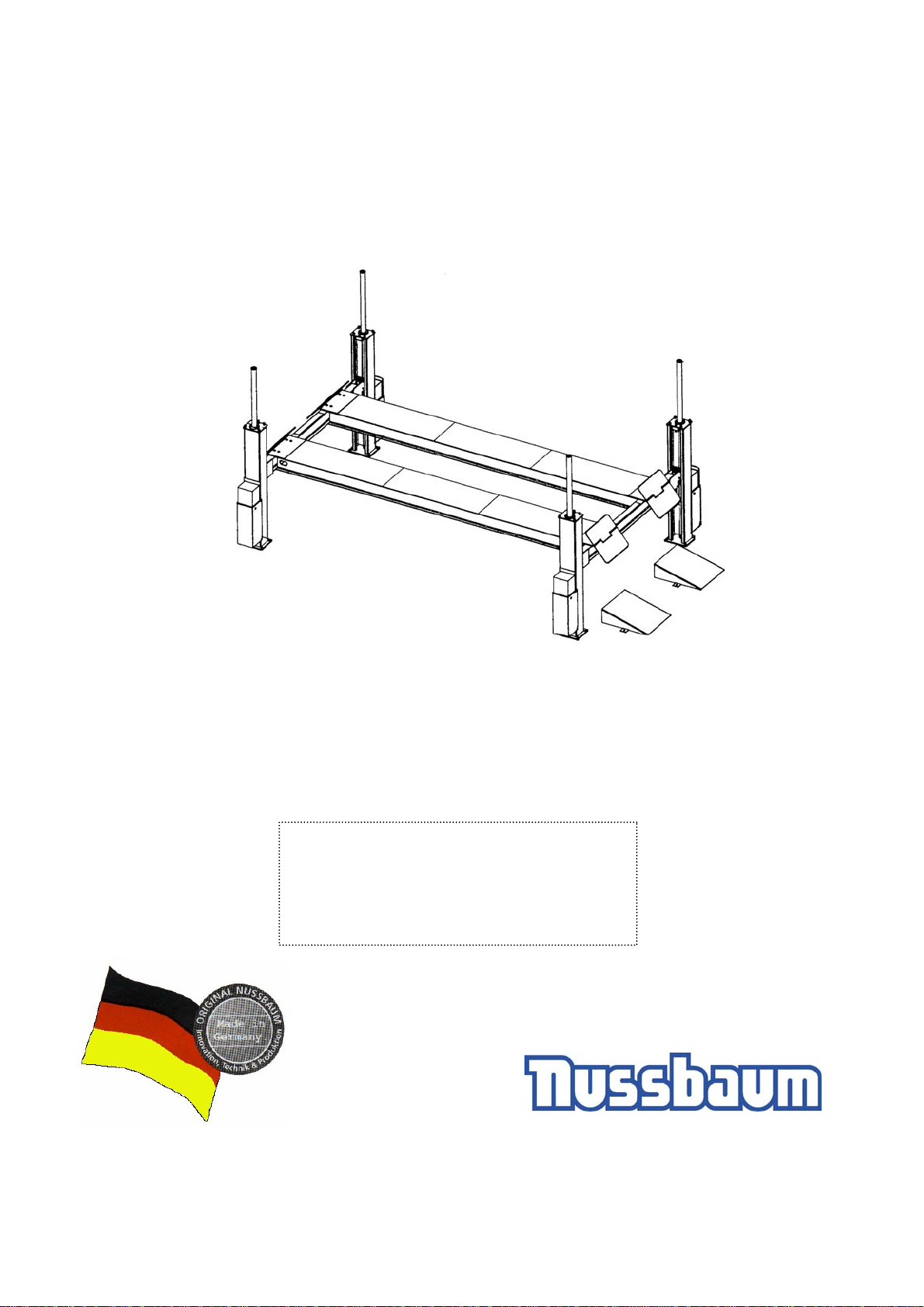
4.80 H SST - 4.300 H SST
4.80 H SST
4.300 H SST E 10
03.doc
Automotive lift date: 10/2003
Manual date: 24.10.2003
Operating Instruction and Documentation
Serial number: .....................................
retailer/ phone
Nußbaum Hebetechnik GmbH & Co.KG//Korker Straße 24//D-77694 Kehl-Bodersweier//Tel: +49(0)7853/8990
Fax: +49 (0)7853/8787//E-mail: [email protected]//http://www.nussbaum-lifts.de
-
-
Page 2

Operating Instruction and Documentation
4.80 H SST- 4.300 H SST
Contents
Foreword.................................................................................................................................3
Record of installation..............................................................................................................5
Record of handing over........................................................................................................... 6
1.Introduction............................................................................................................................. 7
1.1 Installation and check of the automotive lift..................................................................... 7
1.2 Information of Warning.................................................................................................... 7
2.Master document of the automotive lift.................................................................................. 8
2.1 Lift–manufacturer .............................................................................................................8
2.2 Application........................................................................................................................ 8
2.3 Changes at the construction .............................................................................................. 8
2.4 Displacement of the automotive-lift ................................................................................. 8
2.5 CE-Certificate ................................................................................................................... 9
3. Technical Information.......................................................................................................... 11
3.1 Technical ratings.............................................................................................................11
3.2 Safety device...................................................................................................................11
3.3 Data sheet........................................................................................................................13
3.4 Foundation diagram drawing.......................................................................................... 14
4. Safety regulations.................................................................................................................15
5. Operating instructions..........................................................................................................16
5.1 Lifting the vehicle........................................................................................................... 16
5.2 Lowering the vehicle.......................................................................................................16
5.3 Equalisation of the Lift ................................................................................................... 17
5.4 Function Microprocessor / Display-advertisement.........................................................17
5.5 The lift is not in the rule-window ...................................................................................17
5.6 Function of the bypass-switch in case of unequal level of the platform........................17
6.Troubleshooting ....................................................................................................................18
6.1 Driving on an obstacle .................................................................................................... 18
6.1.1 Remove an obstacle.................................................................................................. 19
6.2 Emergency lowering....................................................................................................... 19
6.2.1 Procedure of the emergency lowering...................................................................... 19
6.3 Reset the lift after an emergency lowering..................................................................... 21
7.Inspection and Maintenance of Nussbaum lifts .................................................................... 22
7.1 Maintenance plan of the Mobile column lift...................................................................22
7.2 Cleaning of the Mobile column lift................................................................................. 23
8.Security check.......................................................................................................................24
9.Handing over and Initiation...................................................................................................24
9.1 Regulations .....................................................................................................................24
9.3 Adjusting the rail.............................................................................................................26
9.4 Changing the installation place.......................................................................................26
9.5 Initiation..........................................................................................................................27
First security check before installation ................................................................................. 30
Hydraulic diagram drawing .................................................................................................. 44
Electrical diagram drawing................................................................................................... 46
- 2 -
Page 3
Operating Instruction and Documentation
4.80 H SST- 4.300 H SST
Foreword
Nussbaum-Lifts are a result of long-standing experiences.
The high quality and the superior concept guarantee them reliability, a long lift time and the
economic business.
To avoid unnecessary damages and dangers, read the operating instruction attentive and
observe the contents.
Another or the described purpose going out use is not valid when not as agreed.
This is valid particularly for climb and go.
Company Nussbaum is not liable for damages arising from this. The user carries the risk
a lonely.
For the use belonged:
- to observe all the notice in the operating instruction and
- the following of the inspection and maintenance work and the prescribed tests.
- The instruction for use have to be observed by all persons working with the lift.
- Especially the chapter “Safety/accident Prevention“ has to be observed.
- In addition to the safety remarks of the instructions for use the regulations and
instructions being valid at the place of operation have to be considered.
Obligations of the operator:
The operator is obliged to allow only those persons complying to the following requirement to
work at the unit
- being well acquainted with the basic regulations concerning labour safety and accident
prevention and being trained to operate the unit.
- having read and understood the chapter concerning safety and warning instructions and
confirmed that by their signature.
Dangers when operating with the lift:
The Nussbaum-Lifts are designed and built according to technical standard and the approved
regulations for technical security. Yet, danger for body and life of the operator may turn up
when using the lift inexpertly.
The lift must only be operated :
- for its appropriate use
- in unobjectionable condition concerning technical security.
- 3 -
Page 4
Operating Instruction and Documentation
4.80 H SST- 4.300 H SST
Organising requirements
- The instructions for use are constantly to be kept at the place of operation being at hand
at any time.
- In addition to the instructions for use rules pertaining to other regulations i.e. accident
prevention and environmental rules are to be observed and directed.
- Safety- and danger alert operation of personal is occasionally and by observing the
instructions for use to be controlled.
- As far as required and ordered by regulations personal protective equipment is to be
used
- All safety- and danger-hints at the lift are to be observed!
- Spare parts must comply with technical requirements laid down by the manufacturer.
This is only warranted with original parts.
Consider time intervals given or fixed in instructions for use for repeated
tests/inspections.
Maintenance works, remedy of faults and disposal
- Fixed Adjusting-, maintenance- and inspection works and time intervals including
Details for exchange of parts/part components as mentioned in the instructions for use
are to be adhered.
These works must only be carried out by expert personal.
- After maintenance- and repair works loose screw connections must always be firmly
tightened!
Guarantee and liability
- Our “General conditions of selling and delivering” are in force.
There will be no guarantee or liability for incidents involving injuries or death or damage
to equipment if these incidents are the result of one or more of the following reasons.
- Inappropriate use of the lift
- Inappropriate installation, initiation, operation and maintenance of the lift.
- Use of the lift while one or several security devices do not work, do not work correctly or
are not installed correctly.
- Failure to follow the regulations of the operating instructions regarding transport, storage,
installation, initiation, operation and maintenance of the lift.
- Unauthorized changes to the structure of the lift without first asking the producer.
- Unauthorized changes of adjustments of important components of the lift (e.g. driving
elements, power rating, motor speed, etc)
- Wrong or incorrect maintenance practice.
- Catastrophes, acts of God or external reasons.
- 4 -
Page 5
Operating Instruction and Documentation
4.80 H SST- 4.300 H SST
Filling out and undersigned and copying this sheet and send the original to the
lift manufacturer. The copy remains in the Manual.
Otto Nussbaum Hebetechnik GmbH & Co. KG
Korker Straße 24
D-77694 Kehl-Bodersweier
Record of installation
The automotive lift 4.80 H SST – 4.300 H SST with the
serial number:............................................ was installed on:...............................................
at the firm:................................................. at:.....................................................................
the safety was checked and the lift was started.
The installation was effected from the operating authority/competent
(please delete as applicable).
The safety of the automotive lift was checked from the competent before the initial operation.
The operating authority attest the installation of the automotive lift, the competent attest the
correct initial operation.
............................................ ..................................................... ............................................
date name of the operating authority signature of the operating authority
............................................ ..................................................... ............................................
date name of the competent person signature of the competent person
Service partner:............................................................................................................................
Automotive lift date: 10/03 / Manual date: 24.10.2003
- 5 -
Page 6
Operating Instruction and Documentation
4.80 H SST- 4.300 H SST
Record of handing over
The automotive lift 4.80 H SST – 4.300 H SST with the
serial number:............................................ was installed on:...............................................
at the firm:................................................. at:.....................................................................
the safety was checked and the lift was started.
The persons below were introduced after the installation of the automotive lift. The
introduction was carried out from an erector of the lift-manufacturer or from a franchised
dealer (competent person).
............................................ ..................................................... ............................................
date name signature
............................................ ..................................................... ............................................
date name signature
............................................ ..................................................... ............................................
date name signature
............................................ ..................................................... ............................................
date name signature
............................................ ..................................................... ............................................
date name signature
............................................ ..................................................... ............................................
date name signature
............................................ ..................................................... ............................................
date name of competent signature of the competent
Service partner:............................................................................................................................
- 6 -
Page 7
Operating Instruction and Documentation
4.80 H SST- 4.300 H SST
1.Introduction
The document ”Operating Instructions and Documentation” contains important
information about installation, operation and maintenance of the automotive lift.
To furnish proof of installation of the automotive lift the form ”Record of Installation”
must be signed and returned to the manufacturer.
To furnish proof of the singular, felt this documentation contains forms. The forms should
be used to document the checks. They should not be removed from this documentation.
Every Changes to the construction and displacement of the automotive lift must be
registered in the ”Master document” of the lift.
1.1 Installation and check of the automotive lift
Only specialist staff is allowed to do work concerning safety and to do the safety checks of
the lift. They are called experts and competent person in this document.
Experts are persons (for example self-employed engineers, experts) which have
received instruction and have experience to check and to test automotive lifts.
They know the relevant labour and accidents prevention regulations.
Competent person are persons who have acquired adequate knowledge and experience
with automotive lifts. They took part in training from the lift-manufacturer
(servicing technicians of the manufacturer or dealer, are competent)
1.2 Information of Warning
To show danger and to show important information the three symbols below are used. Pay
attention to those passages, which are marked with these symbols
Danger! This sign indicates danger to life. Inexpert handling of the described
operation may be dangerous to life.
Caution! This sign cautions against possible damage to the automotive lift or other
material defects in case of inexpert handling .
Attention! This sign indicates for an important function or other important
notes.
- 7 -
Page 8
Operating Instruction and Documentation
4.80 H SST- 4.300 H SST
2.Master document of the automotive lift
2.1 Lift–manufacturer
Otto Nußbaum Hebetechnik GmbH & Co. KG
Korker Straße 24
D-77694 Kehl-Bodersweier
Germany
2.2 Application
The automotive lift 4.80 H SST – 4.300 H SST is a lifting mechanism for lifting motor
vehicles with a laden weight of up to 8000 kg – 30.000 kg. The max. load distribution
2:1 in or against drive-on direction. The automotive lift is only designed for service at
the vehicles. It is not allowed to carry persons with the lift.
It’s not allowed to install the standard-automotive lift in a hazardous location or
washing bays.
2.3 Changes at the construction
Changes at the construction, expert checking, resumption of work (date, kind of
change, signature of the expert)
..................................................................................................................................................
..................................................................................................................................................
..................................................................................................................................................
..................................................................................................................................................
name, address of the expert
........................................................... ............................................................
place, date signature of the expert
2.4 Displacement of the automotive-lift
Displacement of the automotive-lift, expert checking, resumption of work (date, kind
of change, signature of the competent)
..................................................................................................................................................
..................................................................................................................................................
name, address of the competent
........................................................... ............................................................
place, date signature of the competent
- 8 -
Page 9
Operating Instruction and Documentation
4.80 H SST- 4.300 H SST
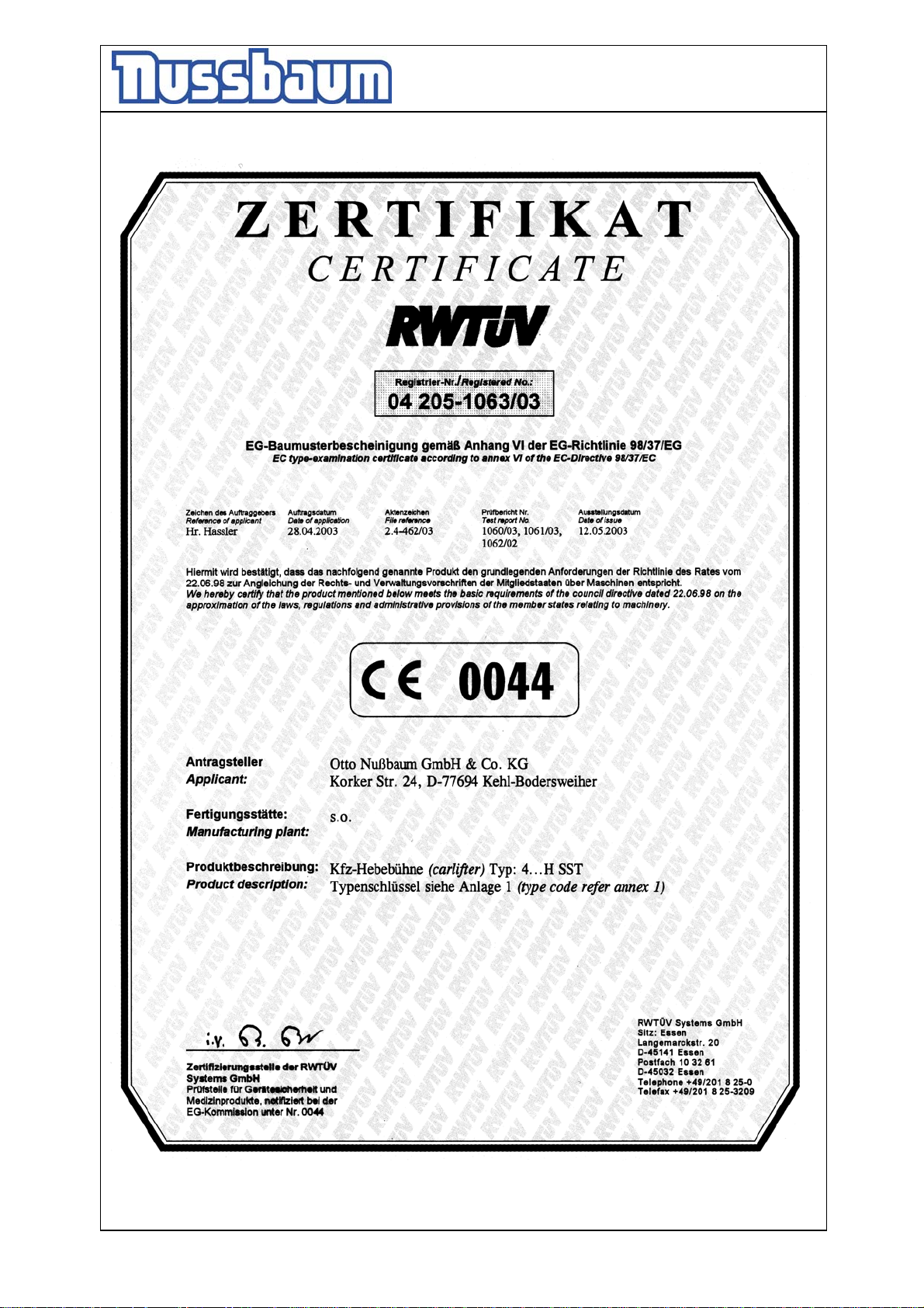
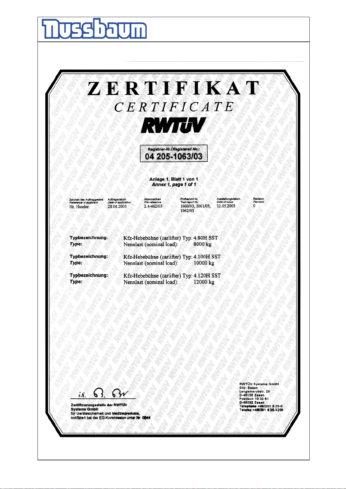
2.5 CE-Certificate
- 9 -
Page 10
Operating Instruction and Documentation
4.80 H SST- 4.300 H SST
- 10 -
Page 11
Operating Instruction and Documentation
4.80 H SST- 4.300 H SST
3. Technical Information
3.1 Technical ratings
Capacity: *after implementation
8000 kg - 30.000 kg
Lifting time approx. 100 sec. with load (*)
Lowering time approx. 55 sec. with load
Line voltage 3 x 400 Volt , 50Hz
Control voltage 24 V
Power rating 1,5 kW
Motor speed 1400 rotation/min
Pump capacity 3 cm3
Hydraulic pressure approx. 220 bar with load
Pressure relief valve approx. 250 bar with load
Pressure relief valve (safety device) max. 35 bar
Oil tank approx. 17 L per hydraulic unit
Sound level ≤ 75 dB(A)
Connection by customer (standard) 3~/N+PE, 400V, 50 Hz
with fuse T16A
(Pay attention to the tension of your state)
3.2 Safety device
1. Pressure relief valve
Overprint-safety of the hydraulic system
2. Holding valve
safety device against unintentional lowering
3. Lockable main switch
safety device against unauthorised operation
4. CE-STOP
safety device against squeeze
5. Hydraulically unlocking safety-system at the cylinder
Safety device against unintentional lowering
6. Safety Star System (SST)
• The SST observed the complete Process of the Lift during „Lifting“ and
„Lowering“.
• The lift will be lowering during the normal work with 0,05 Meter per sec.
- 11 -
Page 12
Operating Instruction and Documentation
4.80 H SST- 4.300 H SST
If the lift descends noticeable faster there may be a problem with the hydraulic
system. The computer-control-system recognizes the problem and switch off the
hydraulic supply for the cylinder.
The Safety-star system locks and the lift stopped.
- Switch off the main switch.
- Check the complete hydraulic system. If the system is defective, call the service of
your retailer.
• The lift can be repaired by an expert, the satisfactory knowledge and experiences
with hydraulic ramps has.
CE-STOP (main lift and wheel free lift)
• The automotive lift stops automatically approx. 320 mm before the lowest position.
- Check the dangerous places of the lift and be sure that there are no objects or people
in the immediate area of the lift or on the lift.
- An acoustic signal is heard until the lift is in the lowest position
Top-Limit
• The Computer-control-system recognizes the top-height position of the lift and
switch off.
- 12 -
Page 13
Operating Instruction and Documentation
4.80 H SST- 4.300 H SST
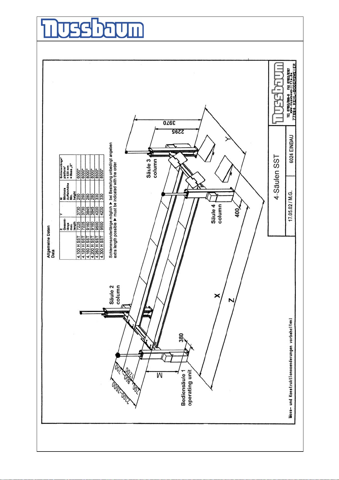
3.3 Data sheet
- 13 -
Page 14
Operating Instruction and Documentation
B
4.80 H SST- 4.300 H SST
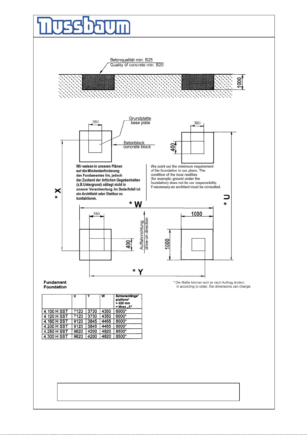
3.4 Foundation diagram drawing
- 14 -
ei Erstellung des Fundamentes ist die unbedingt die Schienenlänge zu prüfen.
Check the length before construction the foundation.
Page 15
Operating Instruction and Documentation
4.80 H SST- 4.300 H SST
4. Safety regulations
Using automotive lifts for working the regulations of accident EN1493/Aug.98 (CEN/TC
98 „ Automotive lifts”) must be observed.
Especially the following regulations are very important:
• During working with the lift the operating instructions must be followed.
• The laden weight of the lifted vehicle mustn’t be more than 8000 kg – 30.000 kg
for automotive lift
• Only trained personnel over the age of 18 years old are to operate this lift.
• During lifting or lowering the vehicle it must be observed from the operator.
• It’s not allowed to stay under the lifted or lowered vehicle (except for the
operator).
• It’s not allowed to transport passengers on the lift or in the vehicle.
• It’s not allowed to climb onto the lift or onto a lifted vehicle.
• The automotive lift must be checked from an expert after changes in construction.
• At vehicles with low under body-freedom or with optional equipment’s, it is to be
tested previously whether damages can appear.
• It’s not allowed to start with operations at the lift before the main switch is
switched off.
• It’s not allowed to install the standard-automotive lift in hazardous location.
- 15 -
Page 16
Operating Instruction and Documentation
4.80 H SST- 4.300 H SST
5. Operating instructions
The Safety Regulations must be observed during working with the automotive lift.
Read the safety regulations in chapter 4 carefully before working with the lift!
5.1 Lifting the vehicle
• Drive vehicle over the lift, longitudinal axes on line of the lift.
• Block the vehicle against rolling, put into gear.
• Check the dangerous places of the lift and be sure that there are no objects or
people in the immediate area of the lift or on the lift.
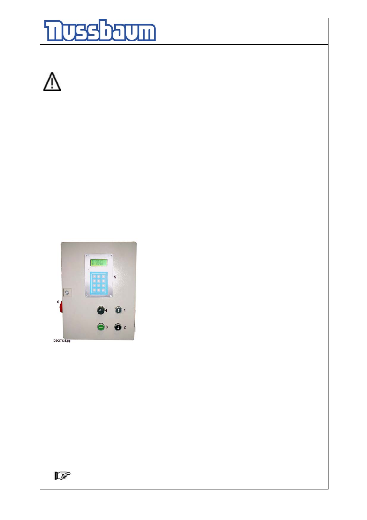
• Switch on the control system; main switch on position ”1” (see pic.1)
• Raise the lift. Press the button „lifting“.
• Lift the vehicle on the working height
• In the display of the operating unit, the momentary height of the platform can be
read.
• Observe the complete process.
Pic 1: Operating unit
1 Button „Lifting“
2 Button „Lowering“
3 Button „equalization the platform“
4 Lighting switch
5 Keyboard and Display
6 Main switch
5.2 Lowering the vehicle
• Check the dangerous places of the lift and be sure that there are no objects or
people in the immediate area of the lift or on the lift.
• Lower the vehicle to the working height or until the platform reaches the lowest
point; press the button „lowering“ .
The lift is raising a few millimetre before the lift lowered (the safety device is
unlocking).
• Observe the complete process.
The lift stops before reaching the lowest position CE-Stop).
- 16 -
Page 17
Operating Instruction and Documentation
4.80 H SST- 4.300 H SST
Control the dangerous places of the lift and be sure that there are no objects or
people in the immediate area of the lift or on the lift. Press the button
“Lowering” until the lift again. You hear an acoustic signal until the lift is
reaching the lowest position.
• Drive the vehicle out of the lift if the lift is in the lowest position.
5.3 Equalisation of the Lift
•
Press the button „Equalization the platform“ at the operation unit. The Platform of
the lift equalize.
5.4 Function Microprocessor / Display-advertisement
• The automotive lift is equipped with a microprocessor. This system recognizes an
unequal of the lift and regulate the hydraulic valves until the lift has the same
height.
• The processor recognizes the present position of the cylinder. The lift switched off
if the automotive lift reaches the top end position or the bottom end position or the
position of the CE-Stop.
• The display shows the present position of the cylinder.
• this display is required also for the service-business, over a foil-keyboard.
5.5 The lift is not in the rule-window
• The lift switched off, if the lift is not in the rule-window of ± 50 mm.
• Read the chapter 5.6 step B to put the lift in the normal Function.
5.6 Function of the bypass-switch in case of unequal level of the platform
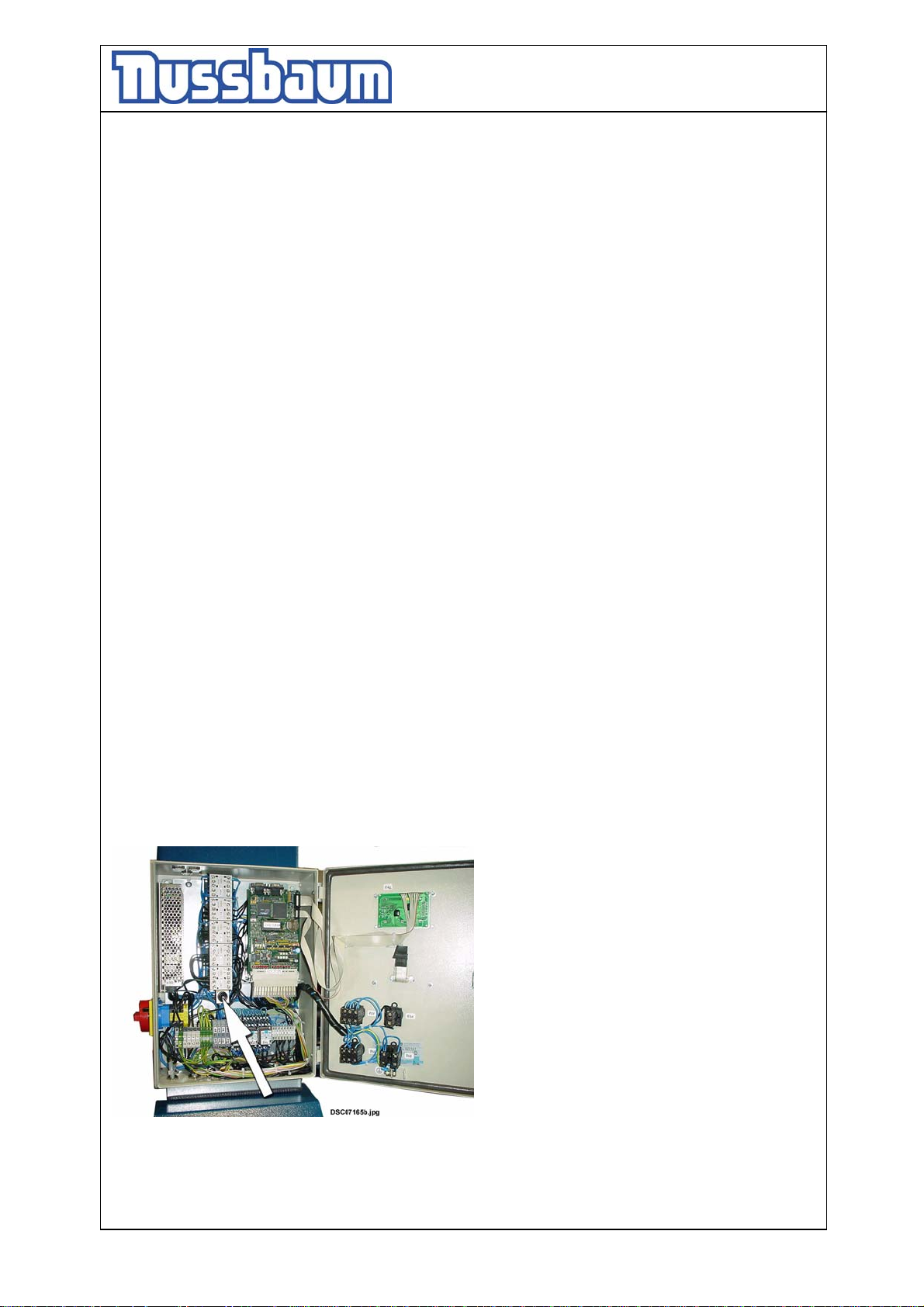
Pic 2: Position of the bypass switch
A) Do not press the button „lifting“ shortly consecutively before the lift was lowered 50
mm. Otherwise the lift will raising over the top limit position. After, it is not possible
to lower the lift again with the button „lowering“.
- 17 -
Page 18
Operating Instruction and Documentation
4.80 H SST- 4.300 H SST
B) In this case it is possible to lower the lift with the button „lowering and the bypass
switch. Press both buttons simultaneously (see pic 2, arrow) until the lift has the
normal function again.
Take careful, otherwise a malfunction can occur.
6.Troubleshooting
If the lift does not work properly, the reason for this might be quite simple. Please check
the lift for the potential reasons mentioned on the following pages. If the cause of
trouble cannot be found, please call the technical service
Problem: Motor does not start!
Potential causes: solution:
- no power supply Check the power supply
- main switch is not engaged Check the main switch
- fuse defective Check the fuse
- the feed line is cut Check the feed line
- Button „lifting“ defective Check the button
- Thermo fuse active Let it cool down
- Out of the rule-window ± 50 mm Read chapter 5.5
Problem: Motor starts, lift does not lifting!
Potential causes: solution:
- The vehicle is too heavy Unload the vehicle
- Level of the oil is too low Fill in new hydraulic oil
- The hydraulic valve is defective Call the lift service
Problem: The lift does not lowered!
Potential causes: solution:
- The lift is standing on a obstacle Read chapter 6.1
- The hydraulic valve is defective Call the lift service
- fuse defective Check the fuse
- button „lowering“ is not pressed or defective Check the button
- the holding valve is defective Call the lift service
- the safety device is locked Call the lift service
6.1 Driving on an obstacle
If the Safety-Star-System recognizes a difference of ± 50 mm between the platforms
then it switches off the lift.
- 18 -
Page 19
Operating Instruction and Documentation
4.80 H SST- 4.300 H SST
6.1.1 Remove an obstacle
Only trained and authorized staff is allowed to work with the DIP-switches! The
main-switch has to be switched off!
• Remove the cover of the operating unit and the control box.
• Press the button “lifting” and the bypass switch simultaneously. (pic 3, arrow).
Raise the lift until the object can be removed.
After it, lower the lift in the lowest position and enforce a reset.
Take careful, otherwise a malfunction can occur.
6.2 Emergency lowering
A emergency lowering is an intervention into the control of the lift and can be
done only by experienced expert.
The emergency lowering must be carried in this order. Otherwise a malfunction
can lead it to damages or lead to danger for body and lives.
Every kind of external leakage has to be removed. This is necessary in particular
before an emergency lowering.
The emergency lowering may only be done by persons which are trained in using
the lift.
Reasons, that can make an emergency lowering necessary, are a defect of the electric
system or disturbances of the valves, etc.
In case of power-failure or defective Valves there is the possibility through suitable
tools to lower the lift in the lowest position, so that the vehicle can be driven off.
6.2.1 Procedure of the emergency lowering
• Switch off the main switch an d safe it. (lock it)
• Remove the covers of hydraulic unit.
• Secure the dangerous place around the lift.
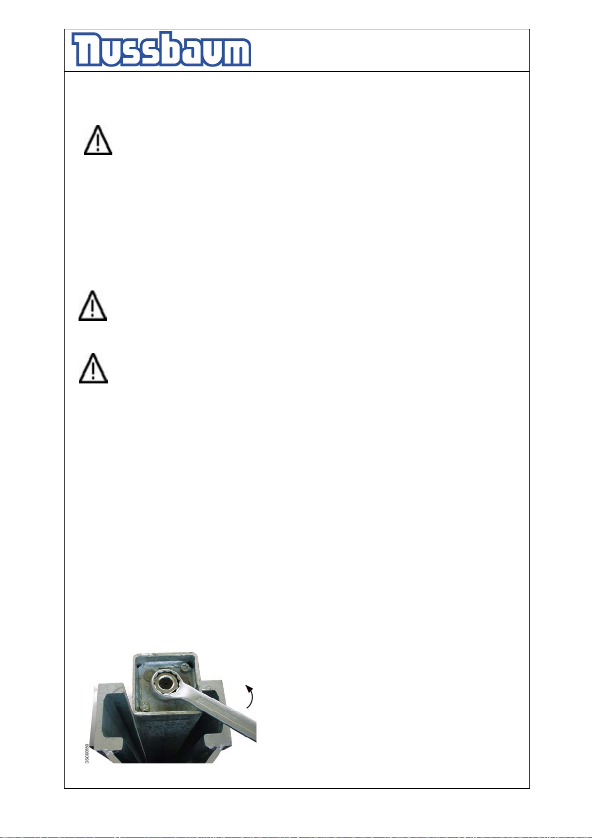
Pic 6:
Loosen and remove the 2 lock nuts with a suitable
tool in arrow direction. Carry out this process at
both columns. (Key 41)
- 19 -
Page 20
Operating Instruction and Documentation
4.80 H SST- 4.300 H SST
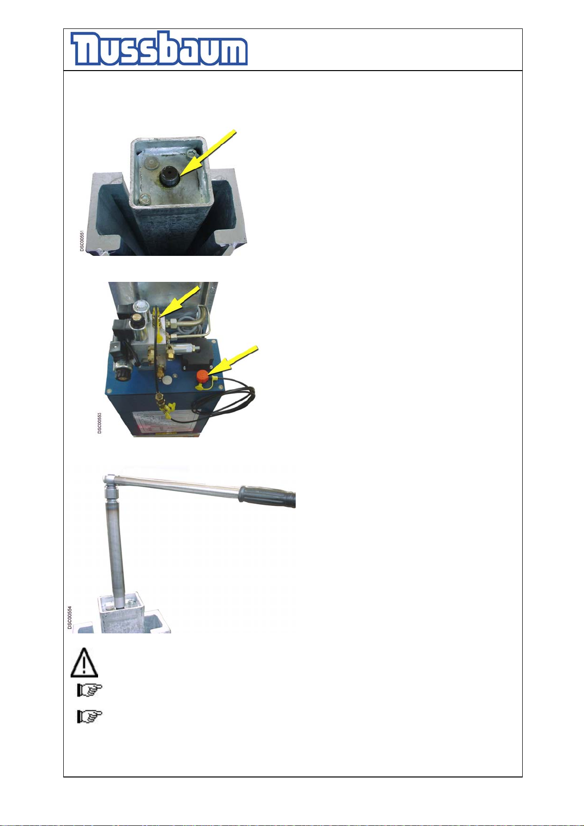
Pic 7:
The piston rod can be stuck through the dirty
deposit at the top of the hole. Use the solvent and
lubricating stuff (for an example WD40) to
loosen the connection. The WD40 is sprayed
generously between the screw thread and the
bore hole (see arrow). The time of the effect
follows the contamination-degree.
Pic 8:
Loosen the cap of the Minimess connection and the
cap of the tank. Fasten the Minimess hydraulic tube
at the screw fitting and put the other end into the
tank.
Pic 9:
Use the long screw thread-bushing and
turns with a suitable tool (key-wideness 24,
available with your dealer,), clockwise.
Lower the lifting carriage only approx. 5cm
– 10 cm. Repeat the process at the next
column. Lower always 5 cm-10 cm until all
lift are in the lowest position.
Repair the defective lift. After it create a
Reset which is described in the operating
instruction.
Attention!! Lower the automotive-lift only approx. 5cm – 10 cm.
Observe the complete emergency lowering process.
Do not work with the lift until the defective parts are changed.
- 20 -
Page 21
Operating Instruction and Documentation
4.80 H SST- 4.300 H SST
You can only work again with the automotive-lift, if it is in a safety-related perfect
condition.
• After it, carry out an reset as described in the operating instruction.
6.3 Reset the lift after an emergency lowering
A reset of the system can be enforced, if the Mobile column lift are in the lowest
position.
An access on the DIP-Switch can take place only with a switched off main switch
and only through instructed, authorized technical personnel.
a) There must not be a vehicle on the lift.
b) Remove the cover of the operating unit.
c) Remove the cover of the electrical box.
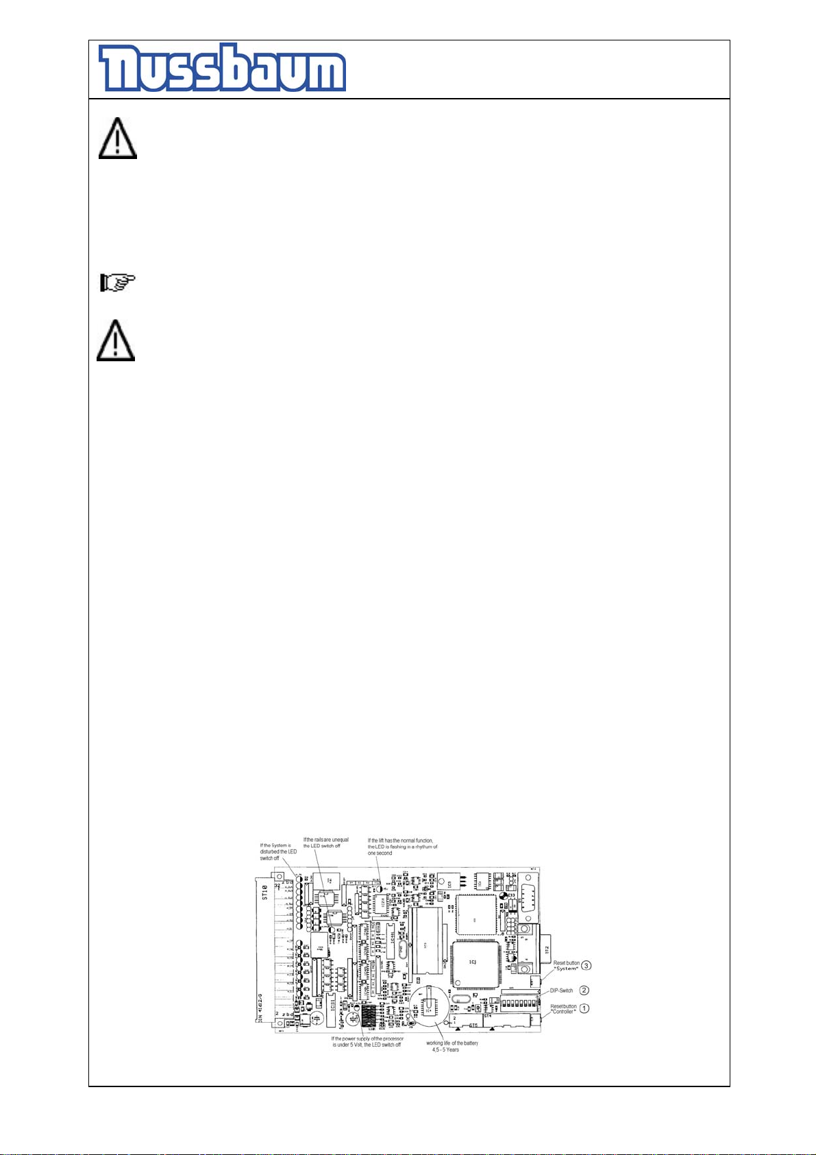
d) Press the button 1 (see pic. 5) and hold it.
e) Switch-off the main switch and wait 5 sec. Hold the reset button.
f) Switch-on the main switch and wait 5 sec. Hold the reset button.
g) Let go off the reset button.
h) Press the button „ lowering“ until both platforms are in the lowest position.
i) If necessary repeat several times the steps d) until h) so that the lift is surely in the
lowest position.
j) After that move the Dip-switch 7 on position „on“.
k) Dip-switch 5 stays on position „on“.
l) Repeat the steps d) until h)
m) After that, move the Dip-switch 7 on position „off“. Dip-switch 5 stays on position „on“.
n) On the computer-board must now three diodes lighten permanently. One additional
diode must be blinking in the frequency of approx. 1 sec.
o) Raise and lower the automotive lift a few times without load. Observe the process.
p) Mount the covers.
pic 5: controller
- 21 -
Page 22
Operating Instruction and Documentation
4.80 H SST- 4.300 H SST
7.Inspection and Maintenance of Nussbaum lifts
Before a maintenance, all preparations are to enforce that with maintenanceworking and repair-working at the lift no danger for body and lives and for
damages of objects exists.
A regular service has to be performed in regular distances of 3 months through the
operator in accordance with following service manual. If the lift is in continuous
operation or dirty environment, the maintenance rate has to be increased.
During daily operation the lift has to be watched carefully for ist correct function. In
case of any malfunction or leakage the technical service has to be informed.
7.1 Maintenance plan of the Mobile column lift
• In case of heavy dirt deposit clean the piston rods of the hydraulic cylinders from
deposit. Remove the cover of the Mobile column lift. If necessary raise the Mobile
column lift with the single-mode in the highest position.
Grease the piston rods with a high capacity lipid (approx. 5 g of S2 DIN51503 KE2G
of the Renolit Company.
• Clean and check the moving parts. Lubricate the moving parts of the lift (hinge bolts,
rolls, sliding surfaces) grease with a multipurpose lipid (example: Auto Top 2000
LTD. Agip).
• Check the colour if necessary make a repair.
• Check the hydraulic tubes for leakage.
• Check the oil level. Fill in a clean, high quality oil (32 cst)in the tank.
• The hydraulic oil has to be changed at least once a year. To change the oil, lower the
lift into the lowest position. Empty the tank and replaced clean oil, approx. 21 litres
are needed. A high quality hydraulic oil is recommended, its should be 32 cst. (e.g.g.
HLP 32 LTD. OEST Company)
Use a ATF-Suffix hydraulic-oil (OEST Company ) if the ambient temperature is
under 5 degree centigrade. After the fill up, the hydraulic oil must be between the
upper and low marking of the oil level gauge.
• Check the welding of the lift.
• Check the safety device of the lift.
• Check the Battery of the controller (ASC). The Battery has a working life between
4 ½ - 5 Years. To avoid a permanent data-loss through an empty battery, the ASC
must be sent for after 4 years into the Nussbaum headquarter. Please contact your
service partner.
• Check the function of the hand lever.
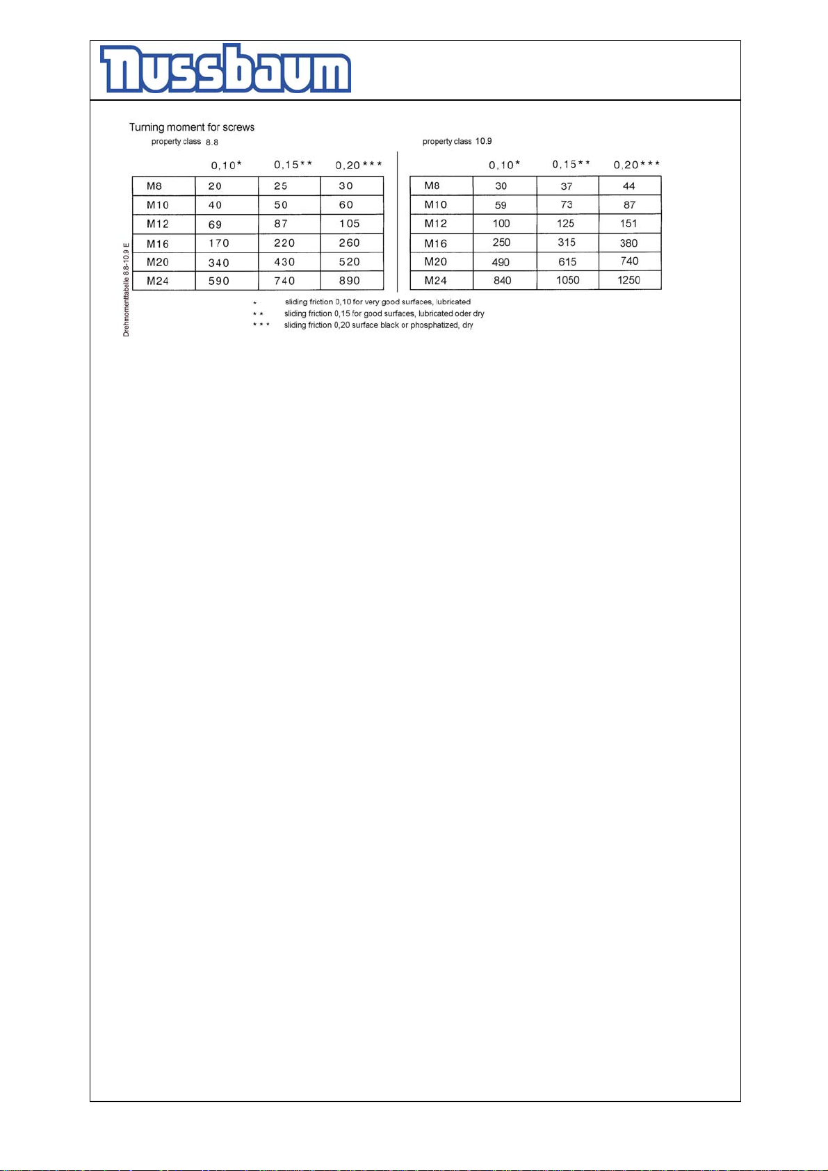
• Check the turning moment of the screws (see the list pic. 6)
- 22 -
Page 23
Operating Instruction and Documentation
4.80 H SST- 4.300 H SST
7.2 Cleaning of the Mobile column lift
A regular and appropriate maintenance served the preservation of the lift.
It can be a prerequisite for claims at possible corrosion.
The best protection for the lift is the regular cleaning of dirt of all manner.
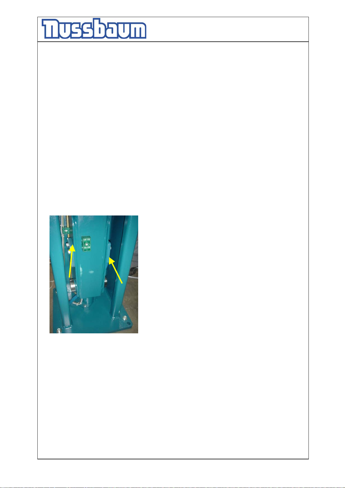
pic 6:
- Including this:
• de-icing salt
• sand, pebble stone, natural soil
• industrial dust of all manner
• water ; also in connection with other environmental influences
• aggressive deposit of all manner
• constant humidity by insufficient ventilation
How often must the lift be cleaned ?
This is dependent on the use, of the working with the lift, of the cleanness of the
workshop and location of the lift. The degree of the dirt is dependent on the season, of
the weather conditions and the ventilation of the workshop.
Under bad circumstances it is necessary to clean the lift every week, but a cleaning
every month can suffice.
Clean the lift and the floor with a non-aggressive and non-abrasive detergent. Use
gentle detergent to clean the parts. Use an standard washing-up liquid and lukewarm
water.
- Do not use for cleaning a steam jet cleaning
- Remove all dirt careful with a sponge if necessary with a brush.
- Pay attention that are no remains of the washing-up liquids on the lift after cleaning.
- Do not use aggressive means for cleaning the workshop floor and the automotive lift.
- A permanent contact with every kind of liquid is forbidden. Do not use any high
pressure device for cleaning the lift.
- 23 -
Page 24
Operating Instruction and Documentation
4.80 H SST- 4.300 H SST
8.Security check
The security check is necessary to guarantee the safety of the lifting during use. It
has to be performed in the following cases:
1. Before the initial operation, after the first installation
Use the form “First security check before initiation”
2. In regular intervals after the initial operation, at least annually.
Use the form “Regular security check at least annually”
3. Every time the construction of that particular lift has been changed.
Use the form “Extraordinary security check”
The first and the regular security check must be performed by a competent
person. It is recommended to service the lift at this occasion.
After the construction of the lift has been changed (changing the lifting
height or capacity for example) and after serious maintenance works
(welding on carrying parts) an extraordinary security check must be
performed by an expert.
This manual contains form with a schedule for the security checks. Please us the
adequate form for the security checks. The form should remain in this manual after they
have been filled out. In the following there is a short description about special safety
devices.
9.Handing over and Initiation
pic 7:
9.1 Regulations
• The installation of the lift is performed by trained technicians of the manufacturer or
its distribution partner. If the operator can provide trained mechanics, he can install
the lift by himself. The installation has to be done according to this regulation.
• The standard lift must not be installed in hazardous locations or washing areas.
• Before installation a sufficient foundation must be proved or constructed.
An even installation place has to be provided. The foundations must be based in a
frost resistance depth, both outside and indoors, where you must reckon with frost.
- 24 -
Page 25
Operating Instruction and Documentation
4.80 H SST- 4.300 H SST
• An electrical supply 3~/N+PE, 400 V, 50 Hz has to be provided. The supply line
must be protected with T16A (VDE0100 German regulation). The minimum
diameter amounts to 2,5 mm².
• All cable ducts have to be equipped with protective coverings to prevent accidents.
9.2 Erection and doweling of the lift
It is necessary to dowel the columns at 4 points and to safe the lift against slipping. For
this a concrete floor without reinforcement, thickness of 1000 mm and quality B 25 is
needed. In case of doubt a test drill is necessary and a dowel is to put in. Afterwards
the dowel is to fasten with a specified torque (example: Liebig 50 Nm). If the necessary
torque is too low or if there are cracks in the concrete floor, a foundation in accordance
with the sheet "foundation plan" is to be erected. As well it has to be paid attention that
the installation place is able to guarantee a horizontal erection of the lift.
• Put the runways on two erection trestles at installation place, pay attention of exactly
difference between the runways (refer to data sheet).
pic. 8
Before mounting the crossbeam, remove the safety metal
sheet.
After mounting the crossbeam, secure it with the metal-
sheet again.
• Position the crossbeams on the face of the runways.
• Fasten the crossbeams on the runways.
• Introduce the connector into the platform and plug it. Observe the number and the
position of the columns.
• Line up operating column (with bubble level) and drill holes for dowel-fixing
through four bore-holes of base plates. Clean bore-holes with pressure air. Put in the
safety dowels with washers in bore hole.
• Check the position of the lift and the position of the operating column again.
• The manufacturer demands LIEBIG safety dowels type B 15 (german dowel
manufacturer) or equal dowels of another manufacturer (with allowance) but observe
their regulations! Before doweling check concrete floor with quality B 25 if the
concrete floor goes to the top edge of the floor. In this case the dowels have to be
- 25 -
Page 26
Operating Instruction and Documentation
4.80 H SST- 4.300 H SST
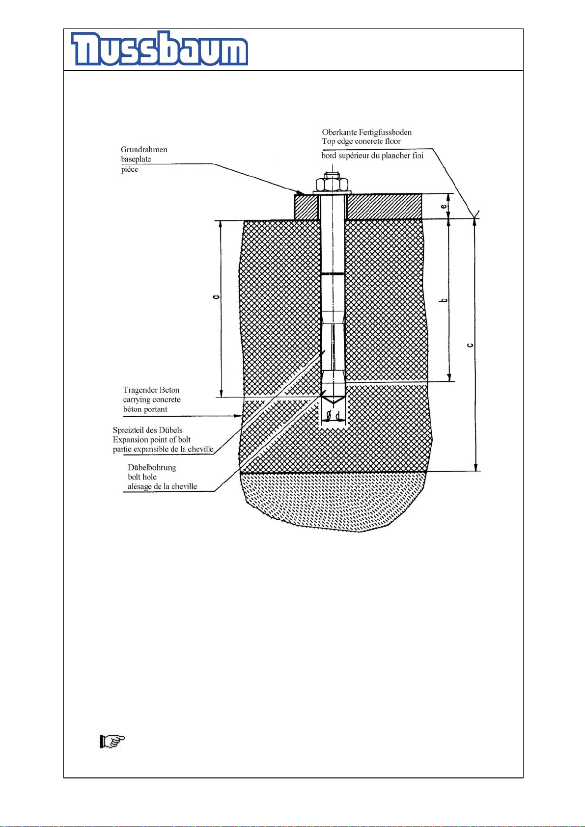
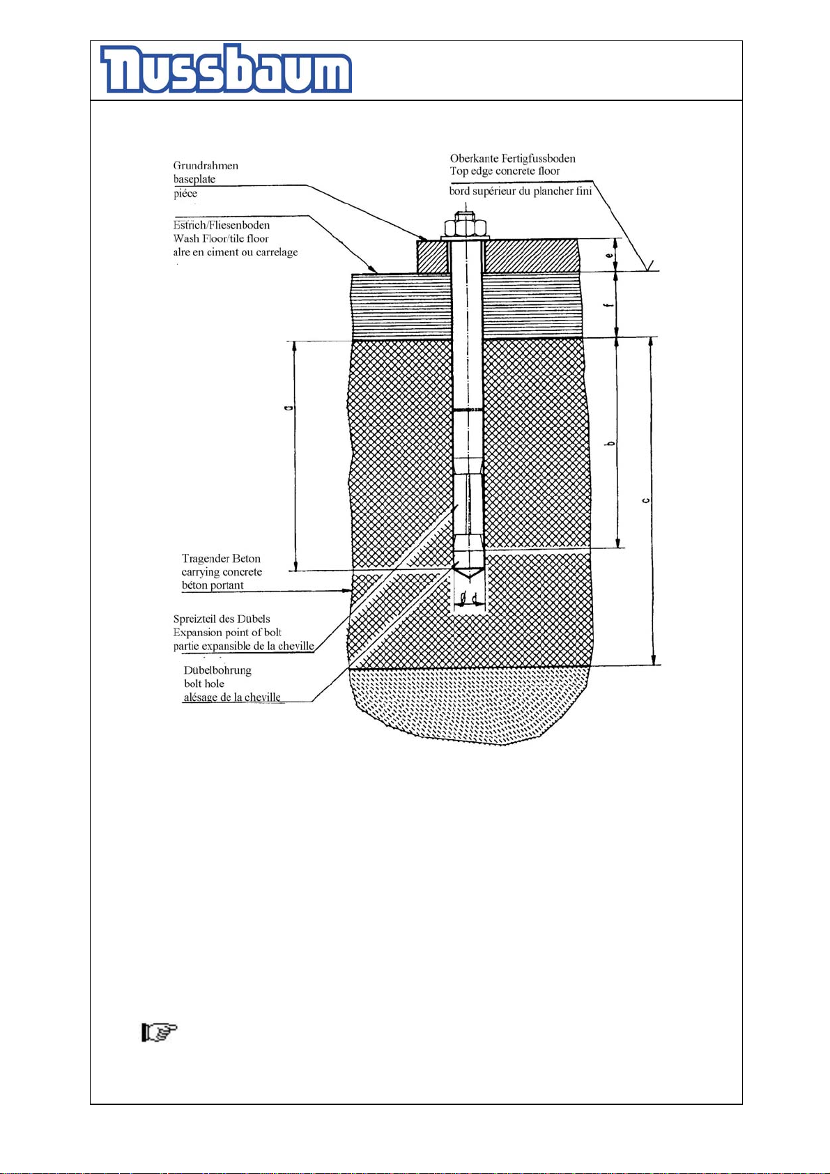
chosen according to picture 9. If the ground is covered with floor tiles, the dowels
have to be chosen according to picture 10.
• Check the position of the columns again. If there is an uneven floor even it with
metal sheets. A continuous contact between the floor and the base plate must be
guaranteed to avoid hollow spaces.
• Tighten the dowels with the dynamometric key (example Liebig-dowels M = 50Nm,
(read the documentation of the dowel manufacturer)
• Fill in the hydraulic-oil approx. 20 litre per column.
• Connect the power supply.
• Press the button „lifting“.
• Check the hydraulic tubes of tightness.
• Remove the erection trestles.
• Lower the lift in the lowest position.
• If necessary create an reset (see chapter 6.3)
• Press the button „lifting“.
• Adjust the sliding guidance at the crossbeam (approx. 4-5 mm movement between
the sliding guidance and the column).
• Mount the cover
• Raise and lower the lift several times with load. Check the torque of the dowels and
check the hydraulic parts for tightness.
9.3 Adjusting the rail
The standard measure between the rails is 1000 mm. It is possible to adjust the rails
+/-200 mm (see the datasheet).
• Lower the lift in the lowest position.
• Drive the vehicle from the lift.
• Loose the screws at the runways and adjust it.
• Tighten the screw.
• The lift has the normal function.
9.4 Changing the installation place
If the place of installation shall be changed, the new place has to be prepared in
according to the regulations of the first installation. The changing should be performed
in accordance with the following points:
• Lower the lift in the lowest position.
• Drive the vehicle from the lift.
• Remove the cover of the operating unit.
• Press the button „lifting“ to raise the lift on a working height
• Lower the lift on the erection trestles..
- 26 -
Page 27
Operating Instruction and Documentation
4.80 H SST- 4.300 H SST
• Disconnect the power supply and the plugs under the platforms.
• Refill the oil.
• Loose the dowels.
• Loose the crossbeam and remove it.
• Transport the lift to the new installation place.
• Install lift in accordance with chapter "Installation and Initiation" of the lift.
Use new dowels, the used dowels can not be used anymore.
A security check must be performed before preoperational by a competent person.
Use form “Regular security check”.
9.5 Initiation
Before the initiation a security check must be performed. Therefore use form: First
security check.
If the lift is installed by a competent person, he will perform this security check. If
the operator installs the lift by himself, he has to instruct a competent person to
perform the security check.
The competent confirms the faultless function of the lift in the installation record and
form for the security check and allows the lift to be used.
Please send the filled installation record to the manufacturer after the installation.
- 27 -
Page 28
Operating Instruction and Documentation
4.80 H SST- 4.300 H SST
pic. 9 choice of the dowel length without floor pavement or tile surface
Table to pic. 9
Liebig-dowels
Dowel type B15/75 B15/95
Drilling depth a 112 112
Min. anchorage depth b 72 72
Thickness of concrete c 160 160
Diameter of bore d 15 15
Thickness of the lift-pieces e 0-40 40-65
Number of dowels 16 16
Starting torque according to dowel manufacturer
You can use equivalent dowels from another dowel manufacturer (with
license) but observe them.
- 28 -
Page 29
Operating Instruction and Documentation
4.80 H SST- 4.300 H SST
pic 10: choice of the dowel length with floor pavement or tile surface
Table to pic. 10
Liebig-dowels
Dowel type B15/70 B15/95 B15/120 B15/145
Drilling depth a 112 137 162 187
Min. anchorage depth b 72 72 72 72
Thickness of concrete c 160 160 160 160
Diameter of bore d 15 15 15 15
Thickness of the lift-pieces e 0-40 40-65 65-90 90-115
Number of dowels 16 16 16 16
Starting torque according to dowel manufacturer
You can use equivalent dowels from another dowel manufacturer (with
license) but observe them.
- 29 -
Page 30
Operating Instruction and Documentation
4.80 H SST- 4.300 H SST
First security check before installation
Filling out and leave in this manual
all defect veri-
kind of check right missing fication remark
----------------------------------------------------------------------------------------------------------------------------------------
Type plate........................................................... F F F ..................................................
Short operating instruction................................. F F F ..................................................
Warning designation.......................................... F F F ..................................................
Sticker “max. capacity”...................................... F F F ..................................................
Designation lifting/lowering............................. F F F ..................................................
Detailed operating instruction........................... F F F ..................................................
Condition concrete.............................................. F F F ..................................................
Safety device of hinge bolt............................... F F F ..................................................
Condition/Function Ramps............................... F F F ..................................................
Condition automotive lift.................................. F F F ..................................................
Condition colour............................................... F F F ..................................................
Construction (deformation, cracking) ............... F F F ..................................................
Torque of the dowels ................................... F F F ..................................................
torque moments of the screws and dowels........ F
Condition operating unit................................... F F F ..................................................
Condition surface piston rod ........................ F F F ..................................................
Condition coverings........................................... F F F ..................................................
Condition electrical wires ............................. F F F ..................................................
Level of hydraulic oil ................................... F F F ..................................................
Closeness of the hydraulic system..................... F F F ..................................................
Condition hydraulic hoses................................. F F F ..................................................
Function test with vehicle.................................. F F F ..................................................
Function safety devices..................................... F F F ..................................................
Condition welding............................................. F F F ..................................................
Function/condition slide-guidance.................... F F F ..................................................
Condition runways............................................ F F F ..................................................
Condition columns............................................ F F F ..................................................
Function CE-Stop............................................. F
( mark here applicable, in case of verification mark in addition to the first mark!)
----------------------------------------------------------------------------------------------------------------------------------------
Security check carried out:..........................................................................................................................................
Carried out the company:............................................................................................................................................
Name, address of the competent:................................................................................................................................
Result of the Check:
F Initiation not permitted, verification necessary
F Initiation possible, repair failures until.........................................................
F No failings, Initiation possible
........................................................ ...........................................................
signature of the expert signature of the operator
If failures must be repaired:
Failures repaired at: .......................... ...................................................signature of the operator
(Use another form for verification!)
F F ..................................................
F F ..................................................
- 30 -
Page 31

Operating Instruction and Documentation
4.80 H SST- 4.300 H SST
Regular security check
all defect veri-
kind of check right missing fication remark
----------------------------------------------------------------------------------------------------------------------------------------
Type plate........................................................... F F F ..................................................
Short operating instruction................................. F F F ..................................................
Warning designation.......................................... F F F ..................................................
Sticker “max. capacity”...................................... F F F ..................................................
Designation lifting/lowering............................. F F F ..................................................
Detailed operating instruction........................... F F F ..................................................
Condition concrete.............................................. F F F ..................................................
Safety device of hinge bolt............................... F F F ..................................................
Condition/Function Ramps............................... F F F ..................................................
Condition automotive lift.................................. F F F ..................................................
Condition colour............................................... F F F ..................................................
Construction (deformation, cracking) ............... F F F ..................................................
Torque of the dowels ................................... F F F ..................................................
torque moments of the screws and dowels........ F
Condition operating unit................................... F F F ..................................................
Condition surface piston rod ........................ F F F ..................................................
Condition coverings........................................... F F F ..................................................
Condition electrical wires ............................. F F F ..................................................
Level of hydraulic oil ................................... F F F ..................................................
Closeness of the hydraulic system..................... F F F ..................................................
Condition hydraulic hoses................................. F F F ..................................................
Function test with vehicle.................................. F F F ..................................................
Function safety devices..................................... F F F ..................................................
Condition welding............................................. F F F ..................................................
Function/condition slide-guidance.................... F F F ..................................................
Condition runways............................................ F F F ..................................................
Condition columns............................................ F F F ..................................................
Function CE-Stop............................................. F
( mark here applicable, in case of verification mark in addition to the first mark!)
----------------------------------------------------------------------------------------------------------------------------------------
Security check carried out:..........................................................................................................................................
Carried out the company:............................................................................................................................................
Name, address of the competent:................................................................................................................................
Result of the Check:
F Initiation not permitted, verification necessary
F Initiation possible, repair failures until.........................................................
F No failings, Initiation possible
F F ..................................................
F F ..................................................
Filling out and leave in this manual
........................................................ ...........................................................
signature of the expert signature of the operator
If failures must be repaired:
Failures repaired at: .......................... ...................................................signature of the operator
(Use another form for verification!)
- 31 -
Page 32

Operating Instruction and Documentation
4.80 H SST- 4.300 H SST
Regular security check
all defect veri-
kind of check right missing fication remark
----------------------------------------------------------------------------------------------------------------------------------------
Type plate........................................................... F F F ..................................................
Short operating instruction................................. F F F ..................................................
Warning designation.......................................... F F F ..................................................
Sticker “max. capacity”...................................... F F F ..................................................
Designation lifting/lowering............................. F F F ..................................................
Detailed operating instruction........................... F F F ..................................................
Condition concrete.............................................. F F F ..................................................
Safety device of hinge bolt............................... F F F ..................................................
Condition/Function Ramps............................... F F F ..................................................
Condition automotive lift.................................. F F F ..................................................
Condition colour............................................... F F F ..................................................
Construction (deformation, cracking) ............... F F F ..................................................
Torque of the dowels ................................... F F F ..................................................
torque moments of the screws and dowels........ F
Condition operating unit................................... F F F ..................................................
Condition surface piston rod ........................ F F F ..................................................
Condition coverings........................................... F F F ..................................................
Condition electrical wires ............................. F F F ..................................................
Level of hydraulic oil ................................... F F F ..................................................
Closeness of the hydraulic system..................... F F F ..................................................
Condition hydraulic hoses................................. F F F ..................................................
Function test with vehicle.................................. F F F ..................................................
Function safety devices..................................... F F F ..................................................
Condition welding............................................. F F F ..................................................
Function/condition slide-guidance.................... F F F ..................................................
Condition runways............................................ F F F ..................................................
Condition columns............................................ F F F ..................................................
Function CE-Stop............................................. F
( mark here applicable, in case of verification mark in addition to the first mark!)
----------------------------------------------------------------------------------------------------------------------------------------
Security check carried out:..........................................................................................................................................
Carried out the company:............................................................................................................................................
Name, address of the competent:................................................................................................................................
Result of the Check:
F Initiation not permitted, verification necessary
F Initiation possible, repair failures until.........................................................
F No failings, Initiation possible
F F ..................................................
F F ..................................................
Filling out and leave in this manual
........................................................ ...........................................................
signature of the expert signature of the operator
If failures must be repaired:
Failures repaired at: .......................... ...................................................signature of the operator
(Use another form for verification!)
- 32 -
Page 33

Operating Instruction and Documentation
4.80 H SST- 4.300 H SST
Regular security check
all defect veri-
kind of check right missing fication remark
----------------------------------------------------------------------------------------------------------------------------------------
Type plate........................................................... F F F ..................................................
Short operating instruction................................. F F F ..................................................
Warning designation.......................................... F F F ..................................................
Sticker “max. capacity”...................................... F F F ..................................................
Designation lifting/lowering............................. F F F ..................................................
Detailed operating instruction........................... F F F ..................................................
Condition concrete.............................................. F F F ..................................................
Safety device of hinge bolt............................... F F F ..................................................
Condition/Function Ramps............................... F F F ..................................................
Condition automotive lift.................................. F F F ..................................................
Condition colour............................................... F F F ..................................................
Construction (deformation, cracking) ............... F F F ..................................................
Torque of the dowels ................................... F F F ..................................................
torque moments of the screws and dowels........ F
Condition operating unit................................... F F F ..................................................
Condition surface piston rod ........................ F F F ..................................................
Condition coverings........................................... F F F ..................................................
Condition electrical wires ............................. F F F ..................................................
Level of hydraulic oil ................................... F F F ..................................................
Closeness of the hydraulic system..................... F F F ..................................................
Condition hydraulic hoses................................. F F F ..................................................
Function test with vehicle.................................. F F F ..................................................
Function safety devices..................................... F F F ..................................................
Condition welding............................................. F F F ..................................................
Function/condition slide-guidance.................... F F F ..................................................
Condition runways............................................ F F F ..................................................
Condition columns............................................ F F F ..................................................
Function CE-Stop............................................. F
( mark here applicable, in case of verification mark in addition to the first mark!)
----------------------------------------------------------------------------------------------------------------------------------------
Security check carried out:..........................................................................................................................................
Carried out the company:............................................................................................................................................
Name, address of the competent:................................................................................................................................
Result of the Check:
F Initiation not permitted, verification necessary
F Initiation possible, repair failures until.........................................................
F No failings, Initiation possible
F F ..................................................
F F ..................................................
Filling out and leave in this manual
........................................................ ...........................................................
signature of the expert signature of the operator
If failures must be repaired:
Failures repaired at: .......................... ...................................................signature of the operator
(Use another form for verification!)
- 33 -
Page 34

Operating Instruction and Documentation
4.80 H SST- 4.300 H SST
Regular security check
all defect veri-
kind of check right missing fication remark
----------------------------------------------------------------------------------------------------------------------------------------
Type plate........................................................... F F F ..................................................
Short operating instruction................................. F F F ..................................................
Warning designation.......................................... F F F ..................................................
Sticker “max. capacity”...................................... F F F ..................................................
Designation lifting/lowering............................. F F F ..................................................
Detailed operating instruction........................... F F F ..................................................
Condition concrete.............................................. F F F ..................................................
Safety device of hinge bolt............................... F F F ..................................................
Condition/Function Ramps............................... F F F ..................................................
Condition automotive lift.................................. F F F ..................................................
Condition colour............................................... F F F ..................................................
Construction (deformation, cracking) ............... F F F ..................................................
Torque of the dowels ................................... F F F ..................................................
torque moments of the screws and dowels........ F
Condition operating unit................................... F F F ..................................................
Condition surface piston rod ........................ F F F ..................................................
Condition coverings........................................... F F F ..................................................
Condition electrical wires ............................. F F F ..................................................
Level of hydraulic oil ................................... F F F ..................................................
Closeness of the hydraulic system..................... F F F ..................................................
Condition hydraulic hoses................................. F F F ..................................................
Function test with vehicle.................................. F F F ..................................................
Function safety devices..................................... F F F ..................................................
Condition welding............................................. F F F ..................................................
Function/condition slide-guidance.................... F F F ..................................................
Condition runways............................................ F F F ..................................................
Condition columns............................................ F F F ..................................................
Function CE-Stop............................................. F
( mark here applicable, in case of verification mark in addition to the first mark!)
----------------------------------------------------------------------------------------------------------------------------------------
Security check carried out:..........................................................................................................................................
Carried out the company:............................................................................................................................................
Name, address of the competent:................................................................................................................................
Result of the Check:
F Initiation not permitted, verification necessary
F Initiation possible, repair failures until.........................................................
F No failings, Initiation possible
F F ..................................................
F F ..................................................
Filling out and leave in this manual
........................................................ ...........................................................
signature of the expert signature of the operator
If failures must be repaired:
Failures repaired at: .......................... ...................................................signature of the operator
(Use another form for verification!)
- 34 -
Page 35

Operating Instruction and Documentation
4.80 H SST- 4.300 H SST
Regular security check
all defect veri-
kind of check right missing fication remark
----------------------------------------------------------------------------------------------------------------------------------------
Type plate........................................................... F F F ..................................................
Short operating instruction................................. F F F ..................................................
Warning designation.......................................... F F F ..................................................
Sticker “max. capacity”...................................... F F F ..................................................
Designation lifting/lowering............................. F F F ..................................................
Detailed operating instruction........................... F F F ..................................................
Condition concrete.............................................. F F F ..................................................
Safety device of hinge bolt............................... F F F ..................................................
Condition/Function Ramps............................... F F F ..................................................
Condition automotive lift.................................. F F F ..................................................
Condition colour............................................... F F F ..................................................
Construction (deformation, cracking) ............... F F F ..................................................
Torque of the dowels ................................... F F F ..................................................
torque moments of the screws and dowels........ F
Condition operating unit................................... F F F ..................................................
Condition surface piston rod ........................ F F F ..................................................
Condition coverings........................................... F F F ..................................................
Condition electrical wires ............................. F F F ..................................................
Level of hydraulic oil ................................... F F F ..................................................
Closeness of the hydraulic system..................... F F F ..................................................
Condition hydraulic hoses................................. F F F ..................................................
Function test with vehicle.................................. F F F ..................................................
Function safety devices..................................... F F F ..................................................
Condition welding............................................. F F F ..................................................
Function/condition slide-guidance.................... F F F ..................................................
Condition runways............................................ F F F ..................................................
Condition columns............................................ F F F ..................................................
Function CE-Stop............................................. F
( mark here applicable, in case of verification mark in addition to the first mark!)
----------------------------------------------------------------------------------------------------------------------------------------
Security check carried out:..........................................................................................................................................
Carried out the company:............................................................................................................................................
Name, address of the competent:................................................................................................................................
Result of the Check:
F Initiation not permitted, verification necessary
F Initiation possible, repair failures until.........................................................
F No failings, Initiation possible
F F ..................................................
F F ..................................................
Filling out and leave in this manual
........................................................ ...........................................................
signature of the expert signature of the operator
If failures must be repaired:
Failures repaired at: .......................... ...................................................signature of the operator
(Use another form for verification!)
- 35 -
Page 36

Operating Instruction and Documentation
4.80 H SST- 4.300 H SST
Regular security check
all defect veri-
kind of check right missing fication remark
----------------------------------------------------------------------------------------------------------------------------------------
Type plate........................................................... F F F ..................................................
Short operating instruction................................. F F F ..................................................
Warning designation.......................................... F F F ..................................................
Sticker “max. capacity”...................................... F F F ..................................................
Designation lifting/lowering............................. F F F ..................................................
Detailed operating instruction........................... F F F ..................................................
Condition concrete.............................................. F F F ..................................................
Safety device of hinge bolt............................... F F F ..................................................
Condition/Function Ramps............................... F F F ..................................................
Condition automotive lift.................................. F F F ..................................................
Condition colour............................................... F F F ..................................................
Construction (deformation, cracking) ............... F F F ..................................................
Torque of the dowels ................................... F F F ..................................................
torque moments of the screws and dowels........ F
Condition operating unit................................... F F F ..................................................
Condition surface piston rod ........................ F F F ..................................................
Condition coverings........................................... F F F ..................................................
Condition electrical wires ............................. F F F ..................................................
Level of hydraulic oil ................................... F F F ..................................................
Closeness of the hydraulic system..................... F F F ..................................................
Condition hydraulic hoses................................. F F F ..................................................
Function test with vehicle.................................. F F F ..................................................
Function safety devices..................................... F F F ..................................................
Condition welding............................................. F F F ..................................................
Function/condition slide-guidance.................... F F F ..................................................
Condition runways............................................ F F F ..................................................
Condition columns............................................ F F F ..................................................
Function CE-Stop............................................. F
( mark here applicable, in case of verification mark in addition to the first mark!)
----------------------------------------------------------------------------------------------------------------------------------------
Security check carried out:..........................................................................................................................................
Carried out the company:............................................................................................................................................
Name, address of the competent:................................................................................................................................
Result of the Check:
F Initiation not permitted, verification necessary
F Initiation possible, repair failures until.........................................................
F No failings, Initiation possible
F F ..................................................
F F ..................................................
Filling out and leave in this manual
........................................................ ...........................................................
signature of the expert signature of the operator
If failures must be repaired:
Failures repaired at: .......................... ...................................................signature of the operator
(Use another form for verification!)
- 36 -
Page 37

Operating Instruction and Documentation
4.80 H SST- 4.300 H SST
Regular security check
all defect veri-
kind of check right missing fication remark
----------------------------------------------------------------------------------------------------------------------------------------
Type plate........................................................... F F F ..................................................
Short operating instruction................................. F F F ..................................................
Warning designation.......................................... F F F ..................................................
Sticker “max. capacity”...................................... F F F ..................................................
Designation lifting/lowering............................. F F F ..................................................
Detailed operating instruction........................... F F F ..................................................
Condition concrete.............................................. F F F ..................................................
Safety device of hinge bolt............................... F F F ..................................................
Condition/Function Ramps............................... F F F ..................................................
Condition automotive lift.................................. F F F ..................................................
Condition colour............................................... F F F ..................................................
Construction (deformation, cracking) ............... F F F ..................................................
Torque of the dowels ................................... F F F ..................................................
torque moments of the screws and dowels........ F
Condition operating unit................................... F F F ..................................................
Condition surface piston rod ........................ F F F ..................................................
Condition coverings........................................... F F F ..................................................
Condition electrical wires ............................. F F F ..................................................
Level of hydraulic oil ................................... F F F ..................................................
Closeness of the hydraulic system..................... F F F ..................................................
Condition hydraulic hoses................................. F F F ..................................................
Function test with vehicle.................................. F F F ..................................................
Function safety devices..................................... F F F ..................................................
Condition welding............................................. F F F ..................................................
Function/condition slide-guidance.................... F F F ..................................................
Condition runways............................................ F F F ..................................................
Condition columns............................................ F F F ..................................................
Function CE-Stop............................................. F
( mark here applicable, in case of verification mark in addition to the first mark!)
----------------------------------------------------------------------------------------------------------------------------------------
Security check carried out:..........................................................................................................................................
Carried out the company:............................................................................................................................................
Name, address of the competent:................................................................................................................................
Result of the Check:
F Initiation not permitted, verification necessary
F Initiation possible, repair failures until.........................................................
F No failings, Initiation possible
F F ..................................................
F F ..................................................
Filling out and leave in this manual
........................................................ ...........................................................
signature of the expert signature of the operator
If failures must be repaired:
Failures repaired at: .......................... ...................................................signature of the operator
(Use another form for verification!)
- 37 -
Page 38

Operating Instruction and Documentation
4.80 H SST- 4.300 H SST
Regular security check
all defect veri-
kind of check right missing fication remark
----------------------------------------------------------------------------------------------------------------------------------------
Type plate........................................................... F F F ..................................................
Short operating instruction................................. F F F ..................................................
Warning designation.......................................... F F F ..................................................
Sticker “max. capacity”...................................... F F F ..................................................
Designation lifting/lowering............................. F F F ..................................................
Detailed operating instruction........................... F F F ..................................................
Condition counter.............................................. F F F ..................................................
Safety device of hinge bolt............................... F F F ..................................................
Condition/Function Ramps............................... F F F ..................................................
Condition automotive lift.................................. F F F ..................................................
Condition colour............................................... F F F ..................................................
Construction (deformation, cracking) ............... F F F ..................................................
Torque of the dowels ................................... F F F ..................................................
torque moments of the screws and dowels........ F
Condition operating unit................................... F F F ..................................................
Condition surface piston rod ........................ F F F ..................................................
Condition coverings........................................... F F F ..................................................
Condition electrical wires ............................. F F F ..................................................
Level of hydraulic oil ................................... F F F ..................................................
Closeness of the hydraulic system..................... F F F ..................................................
Condition hydraulic hoses................................. F F F ..................................................
Function test with vehicle.................................. F F F ..................................................
Function safety devices..................................... F F F ..................................................
Condition welding............................................. F F F ..................................................
Function/condition slide-guidance.................... F F F ..................................................
Condition runways............................................ F F F ..................................................
Condition columns............................................ F F F ..................................................
Function CE-Stop............................................. F
( mark here applicable, in case of verification mark in addition to the first mark!)
----------------------------------------------------------------------------------------------------------------------------------------
Security check carried out:..........................................................................................................................................
Carried out the company:............................................................................................................................................
Name, address of the competent:................................................................................................................................
Result of the Check:
F Initiation not permitted, verification necessary
F Initiation possible, repair failures until.........................................................
F No failings, Initiation possible
F F ..................................................
F F ..................................................
Filling out and leave in this manual
........................................................ ...........................................................
signature of the expert signature of the operator
If failures must be repaired:
Failures repaired at: .......................... ...................................................signature of the operator
(Use another form for verification!)
- 38 -
Page 39

Operating Instruction and Documentation
4.80 H SST- 4.300 H SST
Extraordinary security check
all defect veri-
kind of check right missing fication remark
----------------------------------------------------------------------------------------------------------------------------------------
Type plate........................................................... F F F ..................................................
Short operating instruction................................. F F F ..................................................
Warning designation.......................................... F F F ..................................................
Sticker “max. capacity”...................................... F F F ..................................................
Designation lifting/lowering............................. F F F ..................................................
Detailed operating instruction........................... F F F ..................................................
Condition concrete.............................................. F F F ..................................................
Safety device of hinge bolt............................... F F F ..................................................
Condition/Function Ramps............................... F F F ..................................................
Condition automotive lift.................................. F F F ..................................................
Condition colour............................................... F F F ..................................................
Construction (deformation, cracking) ............... F F F ..................................................
Torque of the dowels ................................... F F F ..................................................
torque moments of the screws and dowels........ F
Condition operating unit................................... F F F ..................................................
Condition surface piston rod ........................ F F F ..................................................
Condition coverings........................................... F F F ..................................................
Condition electrical wires ............................. F F F ..................................................
Level of hydraulic oil ................................... F F F ..................................................
Closeness of the hydraulic system..................... F F F ..................................................
Condition hydraulic hoses................................. F F F ..................................................
Function test with vehicle.................................. F F F ..................................................
Function safety devices..................................... F F F ..................................................
Condition welding............................................. F F F ..................................................
Function/condition slide-guidance.................... F F F ..................................................
Condition runways............................................ F F F ..................................................
Condition columns............................................ F F F ..................................................
Function CE-Stop............................................. F
( mark here applicable, in case of verification mark in addition to the first mark!)
----------------------------------------------------------------------------------------------------------------------------------------
Security check carried out:..........................................................................................................................................
Carried out the company:............................................................................................................................................
Name, address of the competent:................................................................................................................................
Result of the Check:
F Initiation not permitted, verification necessary
F Initiation possible, repair failures until.........................................................
F No failings, Initiation possible
F F ..................................................
F F ..................................................
Filling out and leave in this manual
........................................................ ...........................................................
signature of the expert signature of the operator
If failures must be repaired:
Failures repaired at: .......................... ...................................................signature of the operator
(Use another form for verification!)
- 39 -
Page 40
Operating Instruction and Documentation
:
0.0
4.80 H SST- 4.300 H SST
Manual service operation over the keyboard
Activity only for authorized persons.
One foil-keyboard and one LC-Display for the position-ad and the service-operation are
integrated in the control-box/operating unit.
1. After switching on the installation, the following ad appears on the display
Nussbaum
Hebetechnik
After 5 seconds, one switches automatically to the position-ad.
1. Position-ad
Ad the position of the 4 axes during the normal operation of the lift.
Al-A4: position-value of the 4 axes
A1: 0.0
A2: 0.0
A3: 0.0
A4
Step during the business a mistake on, the axis becomes with the mistake through „-E - „in
the position-ad marked.
The ad changes between the position-ad and the error message.
Examples:
Ad-statuses with synchronism-mistake of axis 1
A1: 50.3 –EA2: 0.0
A3: 0.0
A4: 0.0
Gleichlauffehler
Only when a such mistake was caused, should after telephonic consultation with the
Fa. Nussbaum, phone, 0049 (0)7853-899-0 the service-functions, (sees section 4
(service-operating) become used.
With full function-willingness of the automotive-lift, the operating of the service functions, over the foil-keyboard is forbidden.
- 40 -
Page 41
Operating Instruction and Documentation
4.80 H SST- 4.300 H SST
3. Elapsed time indicator-ad
The number of the working hours can be extract through the operating. Press the button
< * > on the foil-keyboard of the lift.
Ad of the working hours in hours: minute
Only the time is counted, in which the lift
actually drives.
The return to the position-ad takes place automatically anuses approximately 15 seconds or
through operates of the < * > -button.
Function button:
< * > Return to the position-ad (2).
4. Service-operation
The service operation is used for it, during the initiation (installation) or to do the lift after
a disturbance in function again. Only for these two cases, this operating mode of the lift is
intended. Is not allowed to activate these functions, if the lift has the normal function. The
functions of the service operation can be activated over the foil-keyboard appropriate on
the switchbox. To the navigation in the menu system of the service functions serves the
buttons:
<*> menu-point
< #>confirms the menu-point
Through presses and confirming " zurück " you can go back from a submenu into the
higher ranking menu again.
4.1 Log-in in the service-operation
The operator must log-in in the service-operation to activate the service-functions. He
presses during the position-ad the button # and inputs afterwards SERVICE-PIN. After
correct input the PIN takes place automatically the change into the service-main menu.
Retrieval of the password for service-functions
Default-value of the password is ' 1234 '.
This can be altered with demand over the PC-Software, the new password is secured
durably with it in the FRAM of the „Achscontrollers“.
Function button:
<*> Back to the position-ad (2).
<0> ... < 9 > password input
Betriebsstunden
0000000:00 h
Passwort
- - - -
- 41 -
Page 42
Operating Instruction and Documentation
4.80 H SST- 4.300 H SST
4.2 Service-Menu
Dialed menu-point becomes through > < marked
>Gesteuert<
Achse nullen
Hubhöhe
zurück
Function button:
< * > next menu-point dials
< #> menu-point activates
The menu-point becomes >zurück < activated jumps back this to the position-ad.
4.3 STEERED
Both axes of the lift can be driven individually over the function " GESTEUERT ". The
driven axis becomes over “* “marks and demarcates and after it over „#“activates. This
function can be used only in the disturbance-case!
controlled operation - axis 1 active
*1* 50.3
2 0.0
3 0.0
4 0.0
The controlled business over the ad-functions is only possible if the dip-switch stands 5 on
the “Achscontroller” on “ON”!
If the dip-switch 5 is standing on “OFF”, the axe drives over the dip-switch-attitude,
independently from the ad-function.
Over the buttons < 1 >, < 2 >, < 3 >, < 4 > is dialed the axes, the steered procedures
should become. The dialed axes become on the ad through *X * marks.
If the button < lifting > or < lowering > was pressed afterwards, only the select axe can
moved.
! The installation can become destroyed.
Function button:
< * > Abortion and return into the service-menu (4.2)
< l > axe 1 activates / deactivates
< 2 > axe 2 activates / deactivates
< 3 > axe 3 activates / deactivates
< 4 > axe 4 activates / deactivates
- 42 -
Page 43
Operating Instruction and Documentation
4.80 H SST- 4.300 H SST
4.4 Reset of the measuring systems
Over this function, the entire measuring-system of the lift can be put back, (zero). This
function is allowed to only after consultation with the service-headquarters of the Fa.
Nussbaum (phone) + 49 (0)7853-899-0.
Alert message, whether axes should really become reset.
With confirmation of the retrieval with < #> is put down the axes on zero and is jumped
back automatically to the position-ad (2) afterwards.
That zeros of the axes is only possible, if the dip-switch 5 on the „Achscontroller“ stands
on „ON “.
! The installation can become destroyed.
Function button:
< * > Abortion and return into the service-menu (4.2)
< #> axes becomes on zero favored
4.5 Altitudes restricts
The maximum lifting of the lift can be restricted over the menu-point " HUBHOEHE ".
The indicated value can over the button < l > increment and over the button < 0 >
decrement becomes. After election of the desired lift, becomes over < #> the value taken
on. The submenu was deserted.
The submenu was deserted with the button and the changed value was not stored.
Function button:
< * > Demolition and return into the service-menu without stores
< #> store the new value and return into the service-menu
< l > Increases the lifting height
< 0 > Reduces the lifting height
4.6 going back
From a submenu, one can come back into the paramount menu again. Press the button
"ZURÜCK".
Achse nullen?
- 43 -
Page 44
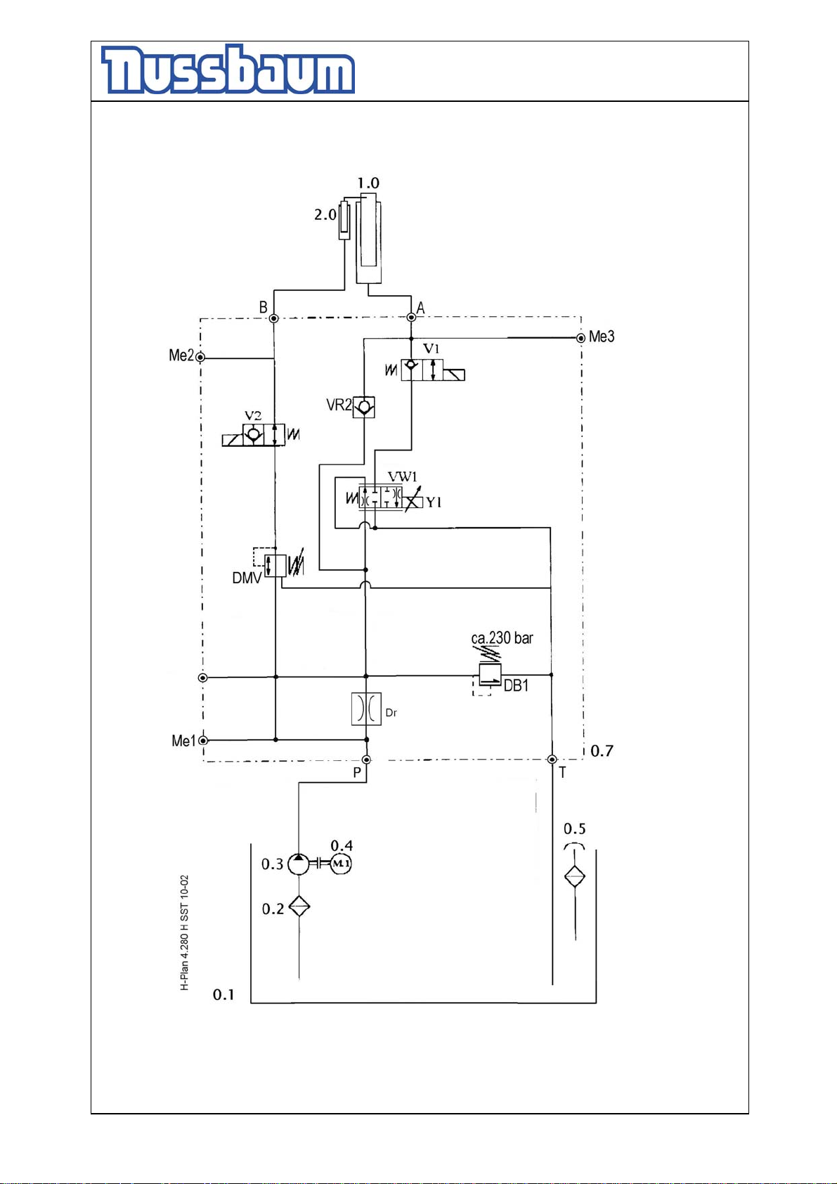
Operating Instruction and Documentation
4.80 H SST- 4.300 H SST
Hydraulic diagram drawing
- 44 -
Page 45
Operating Instruction and Documentation
4.80 H SST- 4.300 H SST
Hydraulic parts list
Pos. Description order number
0.1 oil tank
0.2 oil filter 980012
0.3 gear pump 980486
0.4 suboilmotor 991033
0.5 oil level gauge 980098
0.7 hydraulic block complete 99 540 06 00 5
DB1 pressure relief valve 230 bar 155211
DMV pressure relief valve 30 bar DR08-01-C-V-120V 161350
M1-M3 measure connection 118495
VW1 proportional valve WEP06DA1380240S 161060
DR lowering valve Ø 1,3 mm 161576
V1 2/2 way valve 158502
V2 2/2 way valve 158503
VR2 holding valve 130053
1.0 cylinder
2.0 safety device cylinder
- 45 -
Page 46
Operating Instruction and Documentation
4.80 H SST- 4.300 H SST
Electrical diagram drawing
(valid for 4.80 H SST – 4.300 H SST)
89
:
:
:4.280 H SST
:4.280 H SST/04/02/001
Bl.
Blatt 1
von 12
4.280 H SST 04/02/001Inhaltsverzeichniss
=
+
567
234
SCHALTPLAN
Der Schaltschrank wurde unter Beachtung der anerkannten Regeln der Technik nach
OBJEKT
ANLAGE
KUNDE
SCHALTPLANNR
nach VDE0100g/7.75 Par.22.
worden.
halten, bitten wir,
4.280 H SST
Nussbaum Hebetechnik GmbH & Co.KG
D-77694 Kehl-Bodersweier
Tel.:+49(0)7853/899-0 Fax.:+49(0)7853/8787
27.05.02
Boe
Norm
Gepr.
Bearb.
Datum
0 1
Vor Inbetriebnahme Verdrahtung und Steuerung auf richtige Funktion
- 46 -
Zust.
Page 47
Operating Instruction and Documentation
4.80 H SST- 4.300 H SST
89
Bl.
Blatt 2
von 12
4.280 H SST 04/02/001Inhaltsverzeichniss
=
+
567
234
4.280 H SST
Nussbaum Hebetechnik GmbH & Co.KG
D-77694 Kehl-Bodersweier
Tel.:+49(0)7853/899-0 Fax.:+49(0)7853/8787
Boe
27.05.02
Norm
Gepr.
Bearb.
Datum
0 1
001 Deckblatt
002 Inhaltsverzeichniss
003 Inhaltsverzeichniss
004
005
006 Steuerspannung 24 V Netzteil Achscontroller
007 Steuertasten
008 Achscontroller
009
010
011
012
Inhaltsverzeichniss
- 47 -
Zust.
Page 48
Operating Instruction and Documentation
4.80 H SST- 4.300 H SST
89
Bl.
Blatt 3
von 12
4.280 H SST 04/02/001Inhaltsverzeichniss
=
+
567
234
4.280 H SST
Nussbaum Hebetechnik GmbH & Co.KG
D-77694 Kehl-Bodersweier
Tel.:+49(0)7853/899-0 Fax.:+49(0)7853/8787
27.05.02
Boe
Norm
Gepr.
Bearb.
Datum
0 1
Inhaltsverzeichniss
- 48 -
Zust.
Page 49
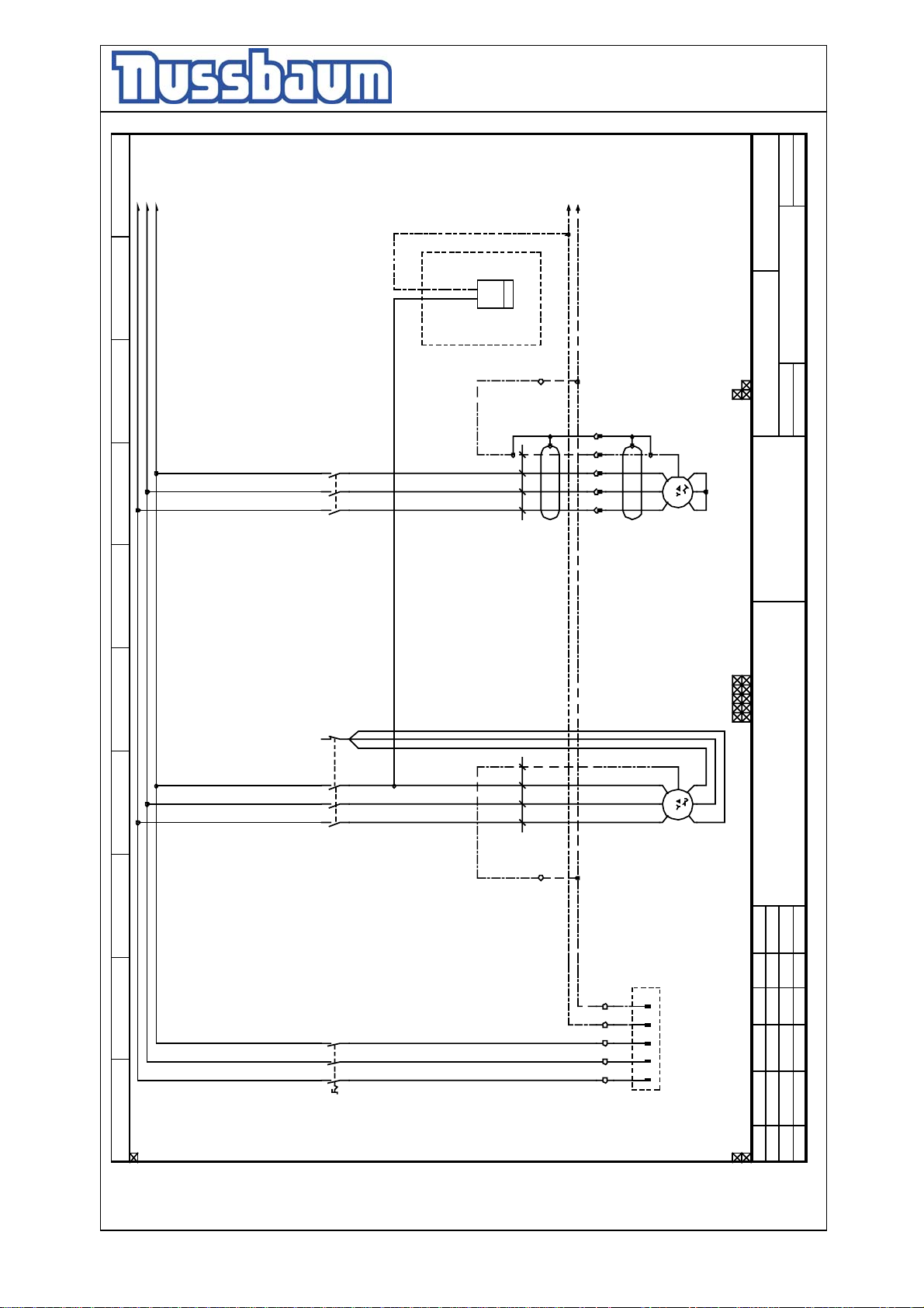
Operating Instruction and Documentation
4.80 H SST- 4.300 H SST
/5.0
/5.0
L1L2L3
/5.0
h
Betriebsstunden-
-4P1
5
6
4
3
1
2
/5.0
/5.0
N
PE
PE
PE
W2V2U2
2 3 PE
2a 3a PE 4a
1a
U1 V1 W1
M
3
1,5kW/3,7A
4.280 H SST 04/02/001
Inhaltsverzeichniss
Bl.
von 12
Blatt 4
=
+
21
5
3
1
-10K2
22
6
4
2
/10.1 /10.5
-10K1
-W1S2
2 3 PE 1
1
-W1S1
PE
-X1
-XS2
PE
U1 V1 W1
M
-4M2
3
-4M1
4.280 H SST
W2V2U2
1,5kW/3,7A
Nussbaum Hebetechnik GmbH & Co.KG
D-77694 Kehl-Bodersweier
Tel.:+49(0)7853/899-0 Fax.:+49(0)7853/8787
Boe
27.05.02
Norm
Gepr.
Bearb.
Datum
Hauptschalter
6
5
4
3
2
1
0 1 2 345 6 78 9
-4Q1
- 49 -
-X1
L2 L3 N PE
L1
L1 L2 L3 N PE
-X0
Zust.
Page 50
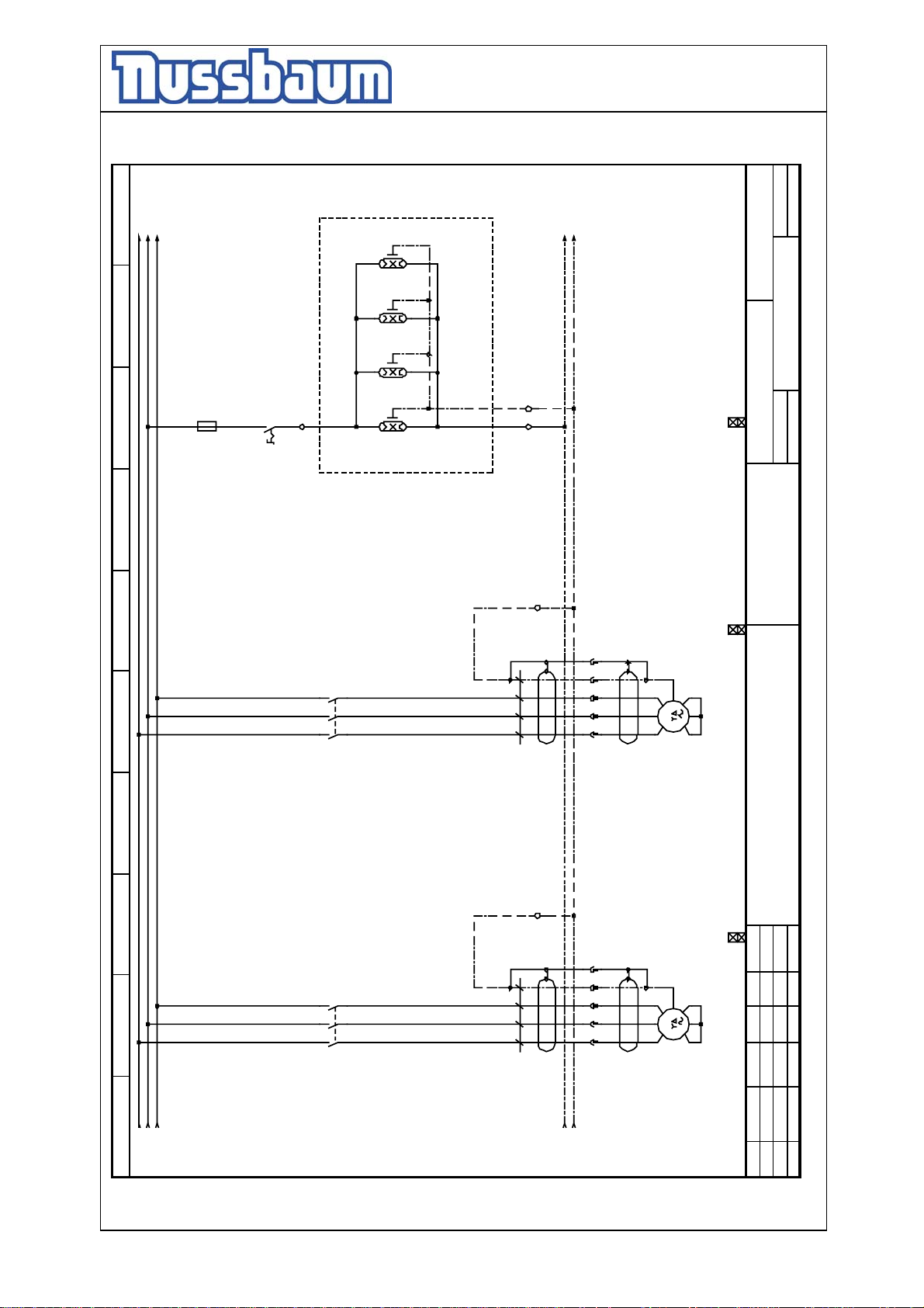
Operating Instruction and Documentation
4.80 H SST- 4.300 H SST
PE
L2
L3
L1
89
Beleuchtung optional
N
4.280 H SST 04/02/001
Blatt 5
Bl.
von 12
-5F1
567
6,3 A
14
13
11
-X1
-5H1 -5H2 -5H3 -5H4
12 PE
=
+
Inhaltsverzeichniss
-5S1
4.280 H SST
PE
5
3
1
6
4
2
-11K2
2 3 PE
-W1S4
2a 3a PE 4a
1a
-XS4
PE
U1 V1 W1
M
W2V2U2
3
-5M2
1,5kW/3,7A
234
5
6
4
3
1
2
/11.2 /11.5
-11K1
0 1
/4.8 /6.1
/4.8
/4.8
- 50 -
PE
Nussbaum Hebetechnik GmbH & Co.KG
D-77694 Kehl-Bodersweier
Tel.:+49(0)7853/899-0 Fax.:+49(0)7853/8787
-X1
27.05.02
PE
W2V2U2
2 3 PE 1
1
-W1S3
2a 3a PE 4a
1a
-XS3
/4.8 /6.1
/4.8 /6.1
U1 V1 W1
M
3
-5M1
Boe
Norm
Gepr.
Datum
Bearb.
1,5kW/3,7A
Zust.
Page 51
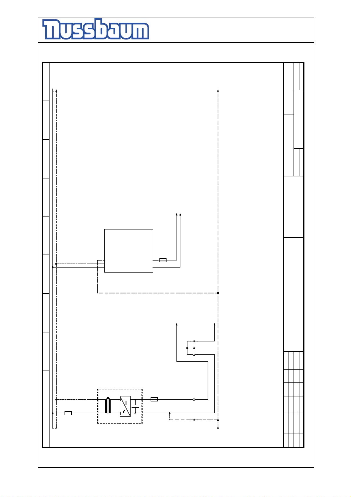
Operating Instruction and Documentation
4.80 H SST- 4.300 H SST
N
L1
89
PE
4.280 H SST 04/02/001
Inhaltsverzeichniss
Blatt 6
Bl.
von 12
=
+
567
234
G
N
LCo m
input:
100-120V 3,5A
200-240V 1,5A
+24V 4,5A
Output:
-6G2
/8.0
/8.0/7.0
L-C
+V
-6F3
+V
Co m
5A
L+ L+C
Versorgung Achscontroller
/7.0
L-
4.280 H SST
Nussbaum Hebetechnik GmbH & Co.KG
D-77694 Kehl-Bodersweier
Tel.:+49(0)7853/899-0 Fax.:+49(0)7853/8787
Boe
27.05.02
Norm
Gepr.
Datum
Bearb.
+
24V
220V
1 A
0 1
-6F1
/5.9 /10.0
/5.9
-6G1
-
2
24V/6,15A
6,3A
-6F2
- 51 -
1 3 3 3
PE
Steuerspannung 24V
-X1
/5.9 /8.2
Zust.
Page 52
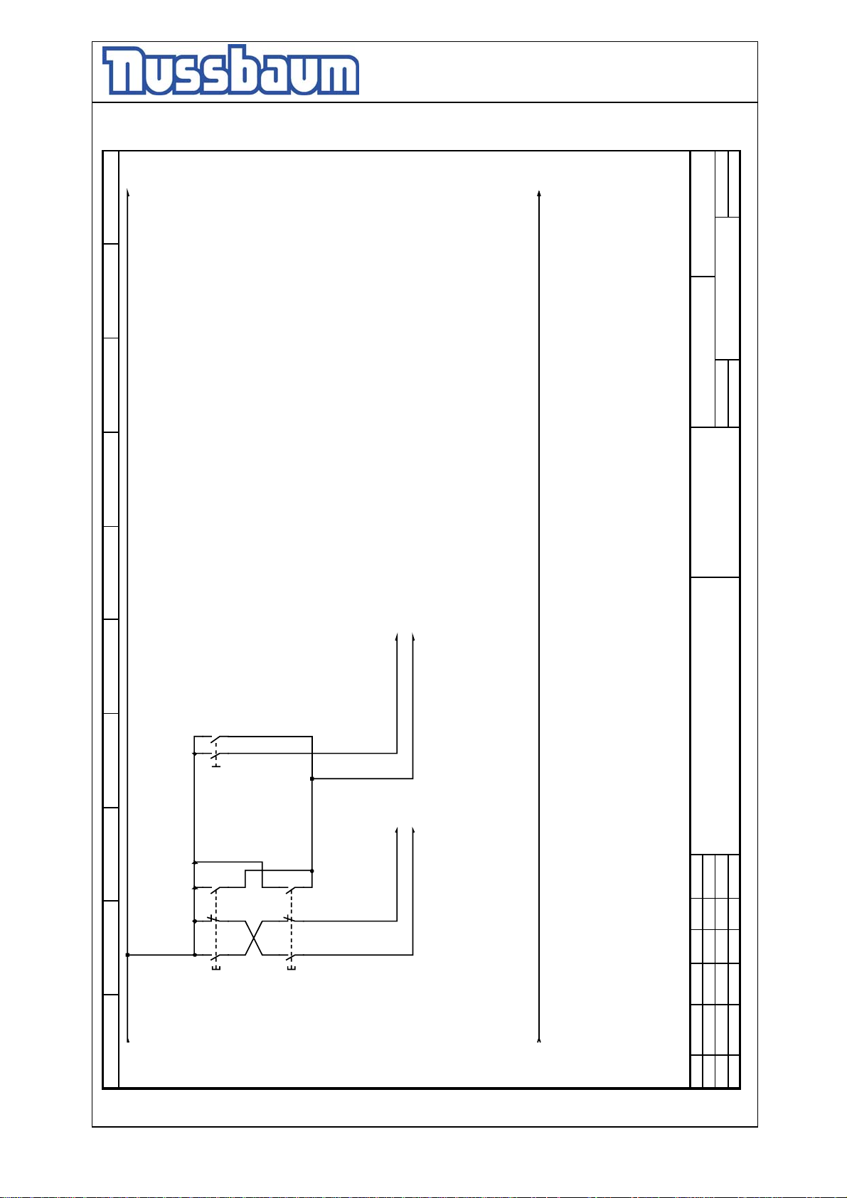
Operating Instruction and Documentation
4.80 H SST- 4.300 H SST
L+
89
L-
4.280 H SST 04/02/001
Inhaltsverzeichniss
Blatt 7
Bl.
von 12
=
+
567
234
23
13
33
21
13
24
14
-7S3
Ausgleich
34
22
14
4.280 H SST
/8.1/8.1
Freig.AchscontrSenken_Achscontr
Ausgleich
/8.1 /8.1
Nussbaum Hebetechnik GmbH & Co.KG
D-77694 Kehl-Bodersweier
Tel.:+49(0)7853/899-0 Fax.:+49(0)7853/8787
33
34
21
22
13
14
Heben_Achscontr
27.05.02
Datum
Boe
Gepr.
Bearb.
Norm
Heben
-7S1
Senken
-7S2
0 1
/6.3 /8.1
- 52 -
/6.3 /8.1
Zust.
Page 53
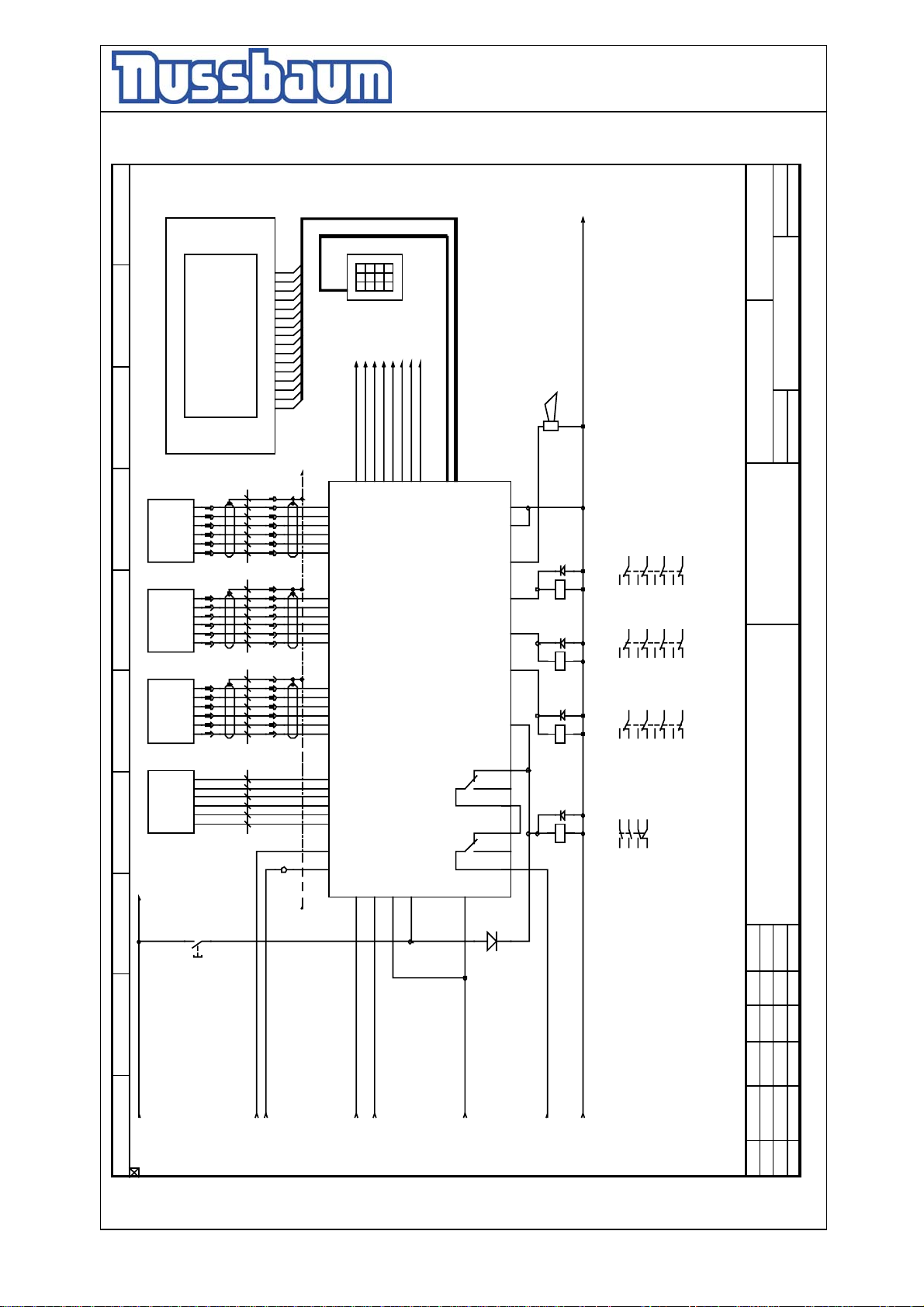
Operating Instruction and Documentation
4.80 H SST- 4.300 H SST
L-
Blatt 8
Bl.
von 12
16
1000
mm
1000
2 3 4 5 6 S
-W3S4
2 3 4 5 6 S 1
-W3S3
2 3 4 5 6 S 1
-W3S2
15
14
13
12
11
10
9
8
7
6
5
4
3
2
1
PE
7c
6c
5c
4c
/8.6/8.6/8.5
3c
2c
1c
- XS4
7c
6c
5c
4c
3c
2c
1c
- XS3
7c
6c
5c
4c
3c
2c
1c
- XS2
mmmmmm
89
1000
1000
-8A2
/S2
S2
/S1
S1
-L
Messgeber
Messgeber
Messgeber
+L
/S2
S2
/S1
S1
-L
+L
/S2
S2
/S1
S1
-L
+L
-XH4
-XH3
-8B4
567
-8B3
-8B2
-XH2
/S2
S2
/S1
-8B1
Messgeber
S1
-L
+L
2 3 4 5 6 1
1
-W3S1
2
-X1
L+
234
13
14
/6.8 /8.6
f24
f22
f20
f18
f16
f14
f12
f10
f8
f6
f4
f2
d24
d22
d20
d18
d16
d14
d12
d10
d8
d6
d4
d2
Z2
Z4
0V +24V
-8A1
/B
B
/A
A
0V
+5V
/B
B
/A
A
0V
+5V
/B
B
/A
A
0V
+5V
/B
B
/A
A
0V
+5V
Prop S1+
d26
Z6
/9.1
PM1
789
/9.1
Prop S1-
d28
Achscontroller ASC 4000
456
/9.1
Prop S2+
d30
PM2
Z8
0*#
123
/9.1
/9.1
Prop S2-
Prop S3+
d32
f26
PM3
Z10
/9.1
Prop S3-
Prop S4-
f28
f30
Z12
Manuell
4.280 H SST 04/02/001
/9.1
/9.1
Prop S4+
=
+
Hupe CE-Stop
-8H1
f32
CAN
Serial
PM4
Display
Tastatur
RS232 Sub D 9pol.Buchse
Sub D 9pol.Stifte
10pol.Pfosten
16pol.Pfosten
GND
Hupe
Sperrvent ile
Si t zvent i l e
Pumpen
Z22
Z20
Z30
A1
A2
Z28
Z26
Z24
-8K4
A1
A2
Sperr
Sitz
11
14
122124
223134
324144
/10.6
/10.6
/10.6
223134
/10.6
/11.3
/11.3
/11.3
324144
/11.3
42
/11.6
/11.6
42
/11.6
/11.6
ventile
Mutter ein
/10.3
/10.3
11
14
122124
ventile
ein
/10.3
/10.3
Inhaltsverzeichniss
4.280 H SST
-8K3
Pumpen
Freigabe
5,7kW
ein
11
14
122124
223134
/10.2
/10.2
/10.5
/10.5
56
34
12
21 22
/10.2
/10.2
/10.2
/11.2
324144
/11.2
42
/11.5
/11.5
Nussbaum Hebetechnik GmbH & Co.KG
D-77694 Kehl-Bodersweier
Tel.:+49(0)7853/899-0 Fax.:+49(0)7853/8787
Z14
Z16
Z18
COM + 24 V
Z32
A1
A2
b26
b24
SM
b22
b32
b30
SM
b28
-8K2
A1
A2
-8K1
-8S1
L-C
L+C
Senken_Achscontr
Heben_Achscontr
Ausgleich
0 1
/6.5
/7.8 /9.1
/6.5
/7.3
/7.3
/7.4
- 53 -
Boe
27.05.02
Norm
Gepr.
Datum
Bearb.
Freig.Achscontr
/7.8 /9.1
/7.4
Zust.
Page 54
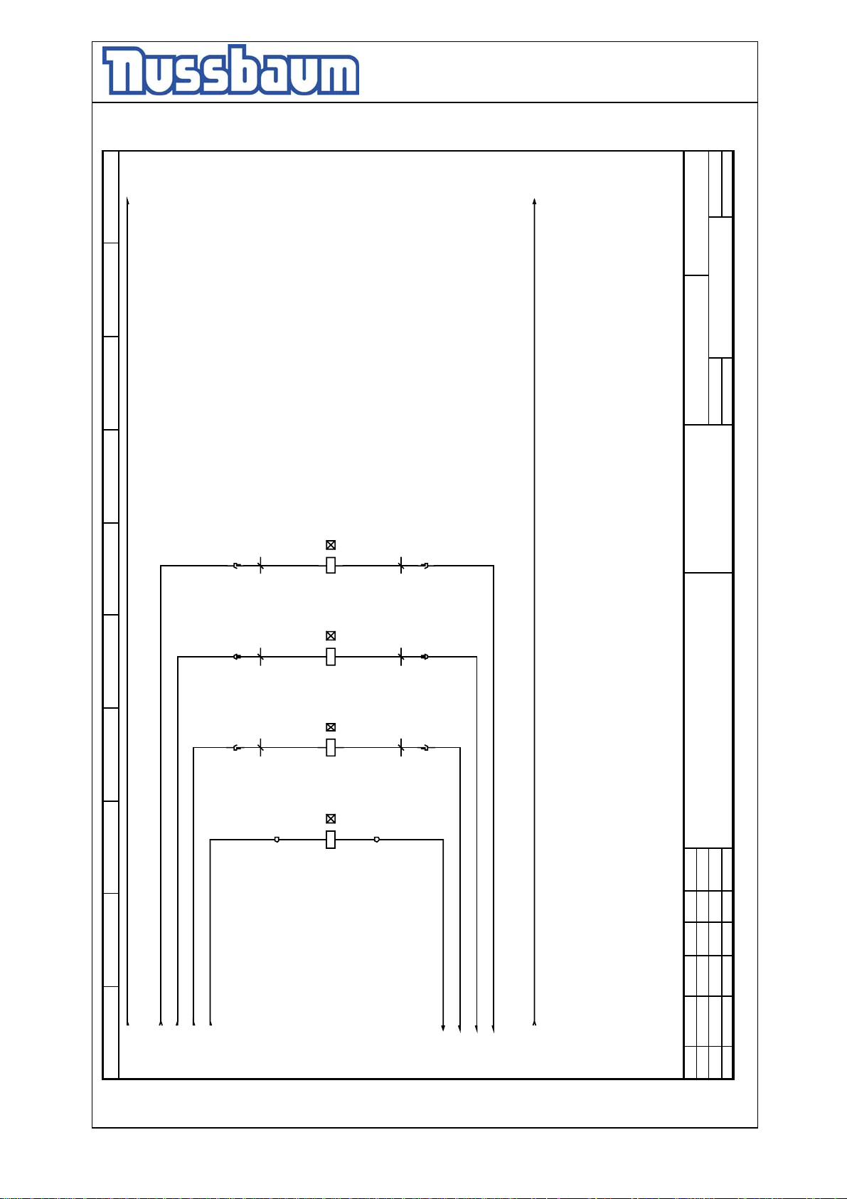
Operating Instruction and Documentation
4.80 H SST- 4.300 H SST
L+
89
L-
4.280 H SST 04/02/001
Inhaltsverzeichniss
Blatt 9
Bl.
von 12
=
+
567
234
1b
-XS4
1b
-XS3
1b
-XS2
4.280 H SST
A1
1
-W2S4
1
-W2S3
1
-W2S2
6
-X1
A2
-9Y4
A1
A2
-9Y3
A1
A2
-9Y2
A1
-9Y1
7
A2
-X1
2b
2
-XS4
-W2S4
2b
2
-XS3
-W2S3
2b
2
-XS2
-W2S2
Prop-Ventil
Prop-Ventil
Prop-Ventil
Nussbaum Hebetechnik GmbH & Co.KG
D-77694 Kehl-Bodersweier
Tel.:+49(0)7853/899-0 Fax.:+49(0)7853/8787
Prop-Ventil
Boe
27.05.02
Norm
Gepr.
Datum
Bearb.
Prop S4+
Prop S3+
Prop S2+
Prop S1+
0 1
/8.3
/8.7
/8.7
/8.7
/8.7
- 54 -
Prop S1-
Prop S2-
Prop S3-
Prop S4-
/8.7
/8.7
/8.7
/8.8 /10.1
/8.7
Zust.
Page 55
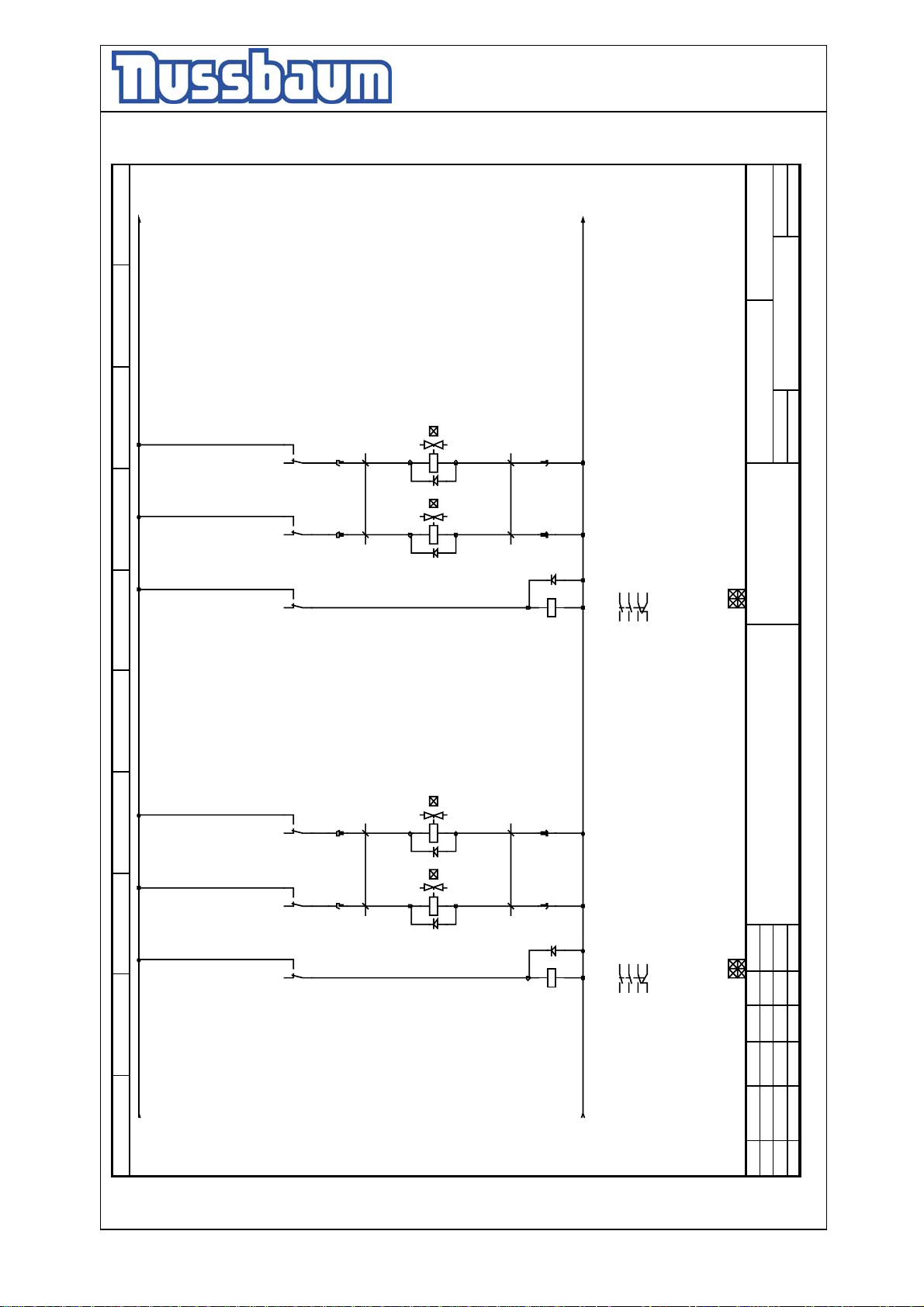
Operating Instruction and Documentation
4.80 H SST- 4.300 H SST
L+1
89
L-
4.280 H SST 04/02/001
Bl.
Blatt 11
von 12
567
234
44
42
41
5b
5
-8K4
44
41
42
-8K3
44
42
3b
3
-W2S4
-XS4
41
-8K2
34
31
32
5b
5
-8K4
34
31
32
-8K3
34
32
-8K2
3b
3
-XS3
-W2S3
31
/8.3 /8.4 /8.5 /8.3 /8.4 /8.5
A1
A2
6b
6
Sperrventil
-11Y4
A1
A2
-W2S4
4b
4
Sitzventil
-XS4
-11Y3
A1
A2
56
34
12
21 22
4kW
Hydraulikpumpe
-11K2
A1
A2
6b
6
Sperrventil
/5.4
/5.4
/5.4
-11Y2
A1
A2
-W2S3
4b
4
Sitzventil
-XS3
-11Y1
A1
A2
56
34
12
21 22
4kW
Hydraulikpumpe
/5.1
/5.1
/5.1
=
+
Inhaltsverzeichniss
4.280 H SST
Nussbaum Hebetechnik GmbH & Co.KG
D-77694 Kehl-Bodersweier
Tel.:+49(0)7853/899-0 Fax.:+49(0)7853/8787
27.05.02
Boe
Norm
Gepr.
Datum
Bearb.
-11K1
0 1
/10.8
- 55 -
/10.8
Zust.
Page 56
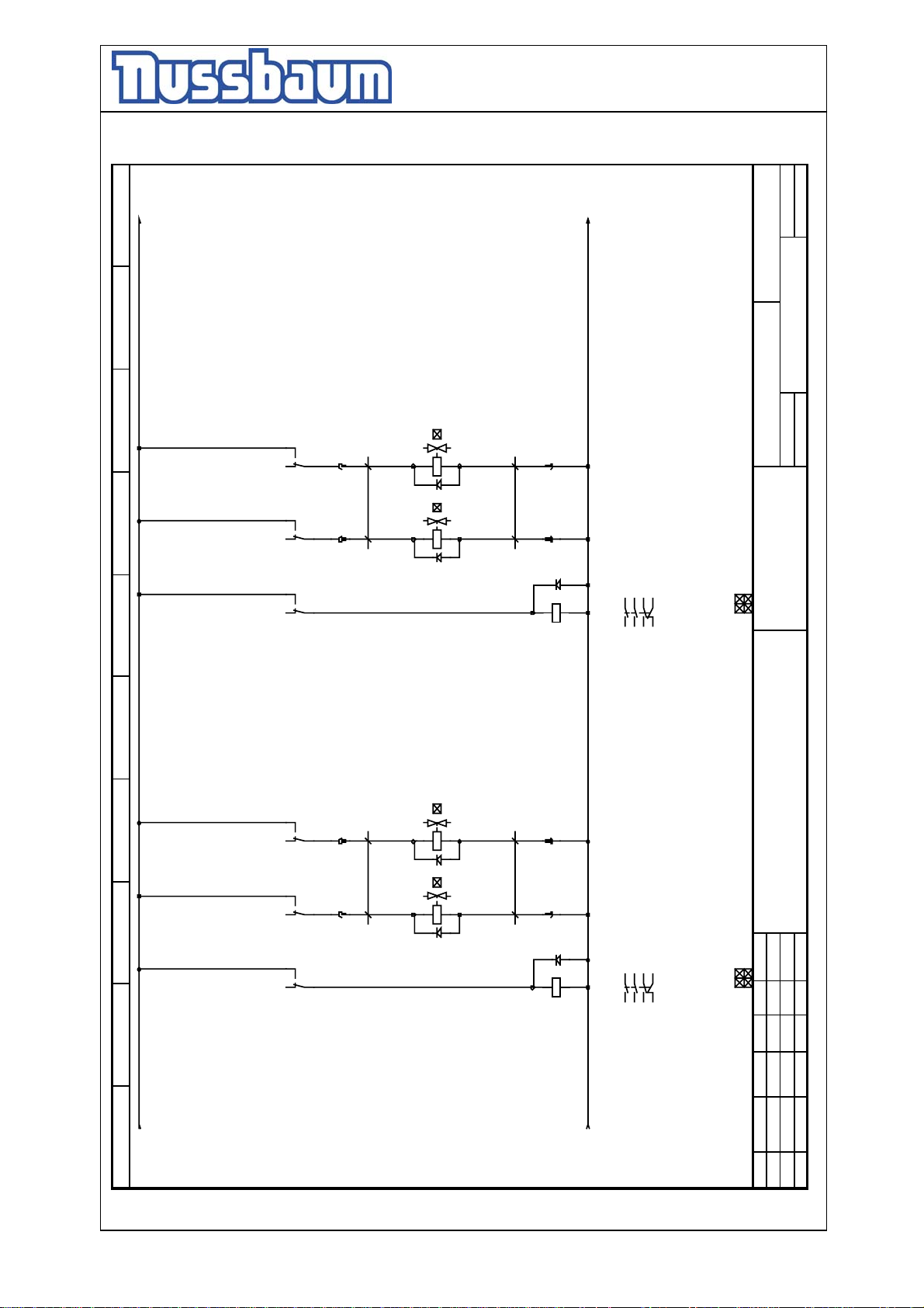
Operating Instruction and Documentation
4.80 H SST- 4.300 H SST
L+1
89
L-
4.280 H SST 04/02/001
Bl.
Blatt 11
von 12
567
234
44
42
44
42
44
42
34
32
34
32
34
32
41
-8K4
41
-8K3
41
-8K2
31
-8K4
31
-8K3
31
/8.3 /8.4 /8.5 /8.3 /8.4 /8.5
-8K2
5b
3b
-XS4
5b
3b
-XS3
5
3
-W2S4
5
3
-W2S3
=
A1
A2
6b
6
Sperrventil
+
Inhaltsverzeichniss
-11Y4
A1
A2
-W2S4
-11Y3
A1
A2
4b
4
Sitzventil
-XS4
4.280 H SST
A1
A2
56
34
12
21 22
4kW
Hydraulikpumpe
-11K2
6b
6
Sperrventil
/5.4
/5.4
/5.4
-11Y2
A1
A2
-W2S3
-11Y1
4b
4
Sitzventil
-XS3
A1
A2
56
34
12
21 22
4kW
Hydraulikpumpe
/5.1
/5.1
/5.1
Nussbaum Hebetechnik GmbH & Co.KG
D-77694 Kehl-Bodersweier
Tel.:+49(0)7853/899-0 Fax.:+49(0)7853/8787
27.05.02
Boe
Norm
Gepr.
Bearb.
Datum
-11K1
0 1
/10.8
- 56 -
/10.8
Zust.
Page 57
Operating Instruction and Documentation
4.80 H SST- 4.300 H SST
89
Bl.
Blatt 12
von 12
4.280 H SST 04/02/001Inhaltsverzeichniss
=
+
567
234
4.280 H SST
Nussbaum Hebetechnik GmbH & Co.KG
D-77694 Kehl-Bodersweier
Tel.:+49(0)7853/899-0 Fax.:+49(0)7853/8787
27.05.02
Boe
Norm
Gepr.
Bearb.
Datum
0 1
- 57 -
Zust.
Page 58
Operating Instruction and Documentation
4.80 H SST- 4.300 H SST
Hersteller Nr.
manufacturer nr.
Fournisseur Nr.
4.280 H SST 04/02/001Materialliste
Bl.
von 5
Blatt 1
Fournisseur
manufacturer
Bauteilbezeichnung
designation
IVP GmbH Kabel 16polig
Displaykabel
IVP GmbH Kabel 10polig
Tastaturkabel
BTR 274i-8K2, -8K3, -8K4
Industrierelais 4W 24V
Finder 94.74.1
Sicherungsklemme Trenner 5*20 mm M4/8.SF
Industrierelaissockel 4 W
Entrelec Schiele 0115657.25-6F1
Entrelec Schiele 0115657.25-6F3
Entrelec Schiele 0115657.25-5F1, -6F2
4.280 H SST
Sicherungsklemme Trenner 5*20 mm M4/8.SF
Sicherungsklemme Trenner 5*20 mm M4/8.SF
article. Nr
Nr. Art
990690
Materialliste material list Liste de Materiel
Bezugsnamen
reference name
identificateur
1 990874
1 Gronau
piece
Nombre
1 1 940257 Display Elek. DEM16481 SY-LY/l-8A2
Nr.
Nr.
lfd.Nr Anz. Art.Nr Hersteller
2 1 991416 Hiller GmbH 046R64LG3 042641103-8E1
44 991352 45365.123.204
44 991353 F 2,8
1 990875
3 1 940265 Conrad Elek. 113-9503-8E2
3 990381
4 3 990267
- 58 -
5 1 990661
1 990475 Streb Feinsicherung 1A
6 1 990661
1 990307 Streb Feinsicherung 5 A
7 2 990661
2 990286 Streb Feinsicherung 6,3 A
Nussbaum Hebetechnik GmbH & Co.KG
D-77694 Kehl-Bodersweier
Tel.:+49(0)7853/899-0 Fax.:+49(0)7853/8787
Boe
27.05.02
Norm
Bearb.
Gepr.
Datum
3 990918 RS 172-8951
18 991330 172-9140
18 991331 172-9134
8 3 990919 RS 172-9077-XH2, -XH3, -XH4
Zust.
Page 59
Operating Instruction and Documentation
4.80 H SST- 4.300 H SST
Hersteller Nr.
manufacturer nr.
manufacturer
Fournisseur Nr.
Fournisseur
Conrad Elektron-8D1, -8D2, -8D3, -8D4
Deltron Compon B/P 228-8H1
Entrelec Schiele 0199091.17-X1
Entrelec Schiele 0199098.26-X1
Entrelec Schiele 0199042.25-X1
Entrelec Schiele 0199118.26-X1
Entrelec Schiele 0299633.06-X1
Entrelec Schiele 0199283.24-X1
IVP GmbH ASC 4000-8A1
M22-DIL-X-7S1, -7S2
M22-XD-S-X7
Kalaschka-8B1, -8B2, -8B3, -8B4
M22-K10
M22-DIL-X-7S3
4.280 H SST 04/02/001Materialliste
Blatt 2
Bl.
von 5
Materialliste material list Liste de Materiel
Bauteilbezeichnung
designation
article. Nr
Bezugsnamen
reference name
4.280 H SST
Sperrdiode 1N40007 1000V;1A
Nr. Art
identificateur
-10D1, -10D2, -10D3
-10D4, -10D5, -10D6
-11D1, -11D2, -11D3
Digisond akustischer Signalgeber
-11D4, -11D5, -11D6
Schutzleiterkl D 2,5/8.P.ADO GR/GE schn-schn
Schutzleiterkl D 1,5/6.P.ADO GR/GE schn-schn
Univ.klemme D 6/8.ADO grau schraub-schn
Schutzleiterkl D 6/8.P.ADO GR/GE schraub-schn
Mini-SL-Klem DR 2,5/8.P.ADO GR/GE schn-schn 15m
Mini-Klemme DR 1,5/6.ADO grau schn-schn 15mm
Achscontroller ASC 4000
HALLELEMENTSCHALTER HDD-16MS60BL,5-55ND1/5
Drucktaste fl. o.Tast.Pl.(M22)
Tastenplatte Pfeil (M22)
Kontaktelement 1S (M22)
Drucktaste fl. o.Tast.Pl.(M22)
Nussbaum Hebetechnik GmbH & Co.KG
D-77694 Kehl-Bodersweier
Tel.:+49(0)7853/899-0 Fax.:+49(0)7853/8787
27.05.02
Boe
Norm
Bearb.
Gepr.
Datum
piece
Nombre
9 16 990652
lfd.Nr Anz. Art.Nr Hersteller
Nr.
Nr.
10 1 990331
11 4 991033 ELMA Elektromot. AT 80B-4-4M1, -4M2, -5M1, -5M2
12 1 990185
13 4 990578
14 4 990593
- 59 -
15 1 990594
16 1 990679
17 14 990702
18 1 940260
19 4 990658
20 2 990130
2 990131
2 990132 M22-AK11
2 990133
21 1 990130
Zust.
Page 60
Operating Instruction and Documentation
4.80 H SST- 4.300 H SST
Hersteller Nr.
manufacturer nr.
Fournisseur Nr.
M22-A
M22-K10
M22-XD-G-X1
M22-WRK-5S1
manufacturer
Fournisseur
M22-AK10
Merz MZ-4Q1
1771383
Oser DS 131-8S1
4.280 H SST 04/02/001Materialliste
Blatt 3
Bl.
von 5
Bauteilbezeichnung
designation
Befestigungsadapter (M22)
Kontaktelement 1S (M22)
article. Nr
Nr. Art
Materialliste material list Liste de Materiel
Tastenplatte Start ( I )(M22)
Wahltaste 2St. Knebel rast.(M22)
Kontaktblock 1S (M22)
4.280 H SST
Hauptsch. Not-Aus 3p 20A 7,5kW
Drucktaster Einbau klein 1S
990833
1771383
Nussbaum Hebetechnik GmbH & Co.KG
D-77694 Kehl-Bodersweier
Tel.:+49(0)7853/899-0 Fax.:+49(0)7853/8787
27.05.02
Boe
Norm
Gepr.
Bearb.
Datum
Bezugsnamen
reference name
lfd.Nr Anz. Art.Nr Hersteller
piece
Nr.
identificateur
Nombre
Nr.
1 990965
2 990133
1 991045
1 990142
22 1 991051
23 5 990842 Lovato BG12.01 (24V DC )-8K1, -10K1, -10K2
-11K1, -11K2
24 1 991032
25 1 990366
26 3 -XS2, -XS3, -XS4
- 60 -
3 1677746
3 990822 1663462
3 990821 1663459
6 990824 1663323
6 990823 1663310
3 990826 1663608
3 990825 1663679
27 3 990819 1679252-XS2, -XS3, -XS4
3 990820 1679294
28 21 990827 1674480-XS2, -XS3, -XS4
Zust.
Page 61
Operating Instruction and Documentation
4.80 H SST- 4.300 H SST
Hersteller Nr.
manufacturer nr.
Fournisseur Nr.
Rittal EB1577.600-4J1
Schmelzer MSE 84/29,5 5371-6G1
Seehausen 155689-9Y1, -9Y2, -9Y3, -9Y4
Fournisseur
manufacturer
Seehausen-10Y1, -10Y3, -11Y1
Seehausen-10Y2, -10Y4, -11Y2
Stifel PG11 C18211 N21-9E1, -9E2, -9 E3, -9E4
Streb 311 PG-10E6, -11E4, -11E10
Streb PG 11-4E4
Bl.
von 5
Blatt 4
4.280 H SST 04/02/001Materialliste
Streb PG 13,5-4E2
Streb PG 9-4E6, -4E8, -4E10
Bauteilbezeichnung
designation
article. Nr
Nr. Art
Materialliste material list Liste de Materiel
EB Elektro-Box gr. m. MtPl. 300x400x155
Trafo 1-ph + Gleichrichter+ C 230V/24V DC 6,15A
Proportionalventil
Sitzventilspule 24 V / 0,8 A 29,9 Ohm
Wegeventilspule 24 V / 0,72 A , 100% ED
Leitungsdose / Ventilstecker
Konusverschraubung PG 11
Gegenmutter PG 11 Messing
4.280 H SST
Gegenmutter PG 13,5 Messing
Gegenmutter PG 9 Messing
Nussbaum Hebetechnik GmbH & Co.KG
D-77694 Kehl-Bodersweier
Tel.:+49(0)7853/899-0 Fax.:+49(0)7853/8787
Boe
27.05.02
Norm
Bearb.
Gepr.
Datum
Bezugsnamen
reference name
identificateur
30 9 990825 1663679-XS2, -XS3, -XS4
9 990826 1663608
31 1 991364
32 1 990835
33 4 155689
21 990828 1672453
piece
Nombre
Nr.
Nr.
lfd.Nr Anz. Art.Nr Hersteller
18 990830 1663365
29 18 990829 1663420-XS2, -XS3, -XS4
-11Y3
34 4 3000249
- 61 -
-11Y4
35 4 BM 4513604LOA
36 12 980654
-10E1, -10E2, -10E7
-10E8, -11E5, -11E6
-11E11, -11E12
37 3 990005
38 1 990006
39 1 990012
40 5 990110
Zust.
Page 62
Operating Instruction and Documentation
4.80 H SST- 4.300 H SST
Hersteller Nr.
manufacturer nr.
Fournisseur Nr.
4.280 H SST 04/02/001Materialliste
Blatt 5
Bl.
von 5
manufacturer
Bauteilbezeichnung
designation
article. Nr
Fournisseur
Streb PG 16-4E14, -5E2, -5E4
Streb PG 21-10E5, -11E3, -11E9
Streb CEE/CT516-X0
Streb 160/MS PG 13,5-4E1
Streb 160/MS PG 9-4E5, -4E7, -4E9
Streb 160/MS PG 16-4E13, -5E1, -5E3
Streb 160/MS PG 11-4E3
4.280 H SST
Gegenmutter PG 16 Messing
Nr. Art
Skintop Kabelverschraubung PG 21
CEKON-STECKER 16 A
Kabelverschraubung PG 13,5 Messing
Kabelverschraubung PG 9 Messing
Kabelverschraubung PG 16 Messing
Kabelverschraubung PG 11 Messing
Nussbaum Hebetechnik GmbH & Co.KG
D-77694 Kehl-Bodersweier
Tel.:+49(0)7853/899-0 Fax.:+49(0)7853/8787
Materialliste material list Liste de Materiel
Bezugsnamen
reference name
identificateur
lfd.Nr Anz. Art.Nr Hersteller
piece
Nombre
Nr.
Nr.
-4E12, -5E6
41 6 990128
-10E4, -11E2, -11E8
42 3 990697
43 1 991270
44 1 991433
45 5 991437
-4E11, -5E5
46 6 991497
-10E3, -11E1, -11E7
- 62 -
47 1 991498
48 1 940268 Thiele Elektr. S100-F24-6G2
27.05.02
Datum
Boe
Bearb.
Gepr.
Norm
Zust.
 Loading...