


1
NFW-560
Quick Installation Guide

2
Table of Contents
Quick Installation Guide..........................................................................3
Hardware Installation ........................................................................................4
Basic System Configuration ...............................................................................7
Appendix: Product Statement..........................................................................21

3
Quick Installation Guide
4
Hardware Installation
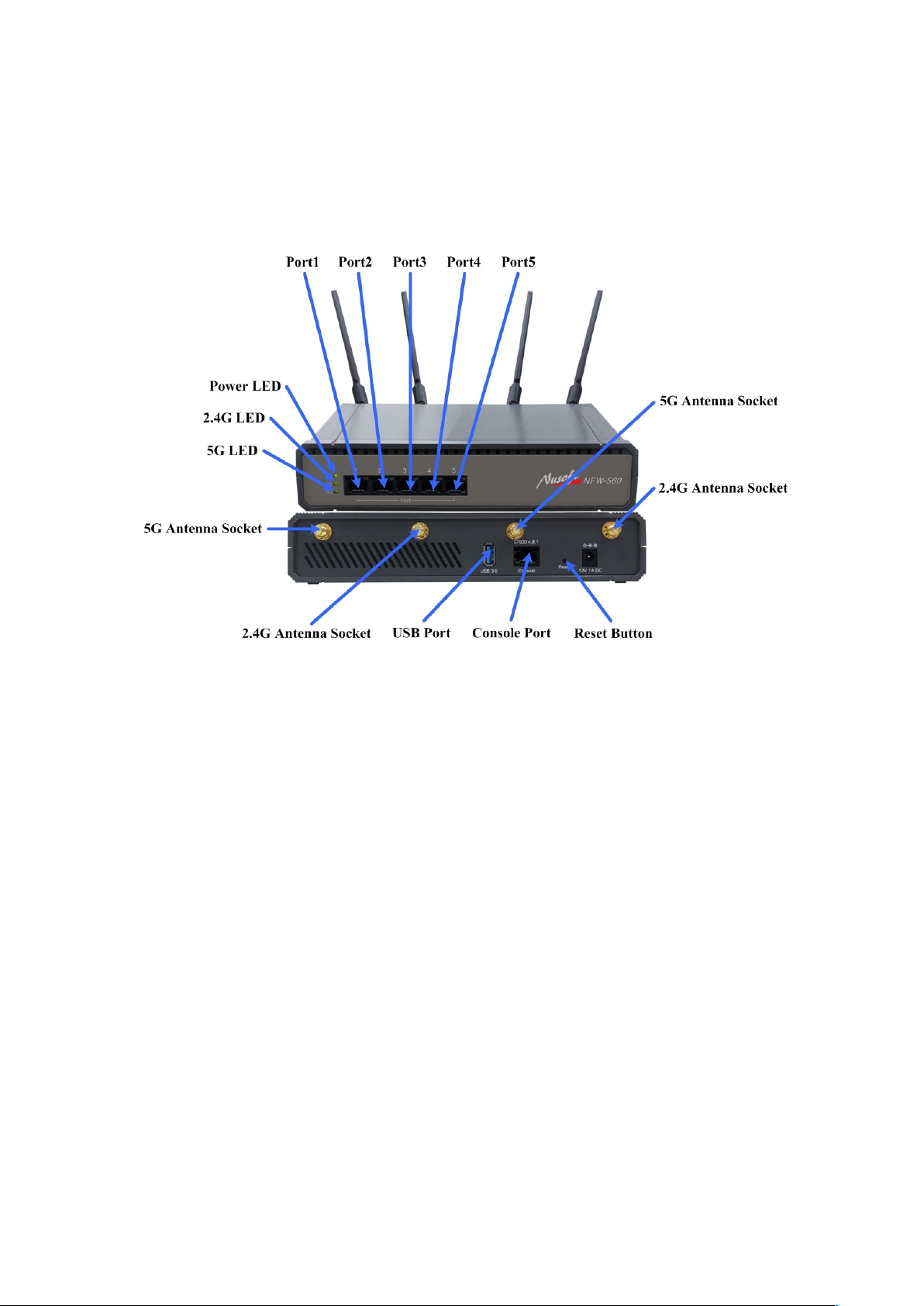
H.1 Front panel:
(Figure H-1)
Figure H-1 Front Panel of the NFW-560
Power LED: Lights up in green when power is on.
2.4G LED: Steady green indicates 2.4G Wi-Fi is enabled. Flashing green
indicates users are accessing the Internet via 2.4G Wi-Fi.
5G LED: Steady green indicates 5G Wi-Fi is enabled. Flashing green indicates
users are accessing the Internet via 5G Wi-Fi.
Console Port: Uses a RJ-45 connector for troubleshooting or, if needed, resetting
the device to the factory default settings.
Port 1 / 2 / 3 / 4 / 5 can be defined as:
LAN Port: For connecting to a switch.
WAN Port: For connecting to a perimeter router.
DMZ Port: For providing the public with services, such as email or Web,
using a physically-separated network segment, while at the same time
preventing any potential security threats.
2.4G Antenna Socket: Connects the 2.4G antenna to NFW-560. (using the
accessory 5dBi omni-directional antenna)
5G Antenna Socket: Connects the 5G antenna to NFW-560. (using the accessory
5dBi omni-directional antenna)

5
USB Port:
Connects the USB disk (a hard disk is recommended) for storing the
operation logs. (Note: The USB disk is required to be formatted before using.
Therefore, make sure to back up your data)
Connects the 3G/4G modem.
Reset Button: For resetting NFW-560 to factory default settings.
Note:
1. Port LED Indications:
Flashing green indicates that packets are processed through the device.
Steady green indicates a link speed at 10/100/1000 Mbps.
2. When connecting both USB disk and 3G/4G modem to the USB port, a USB hub
with power adapter is required.
6
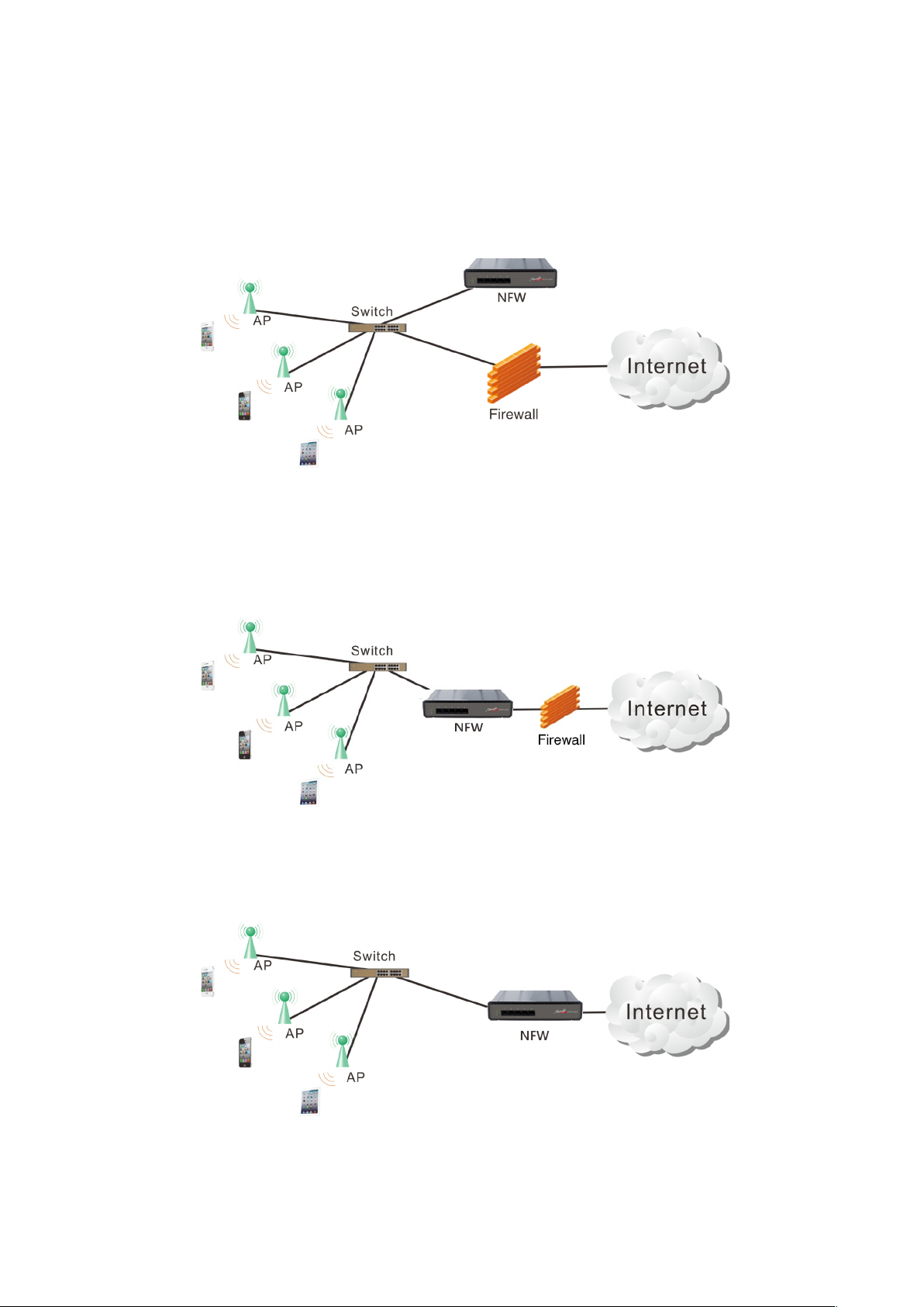
H.2 NFW-560 Deployment:(Figure H-2)
Non-inline mode: The unit is attached to your LAN switch without any network
interference. It is best suited for a network where management is needed for
wireless clients.
(Figue H-2)
Figue H-2 NFW-560 Deployed in Non-inline Mode
Inline mode: The unit is deployed between your existing firewall and LAN
without a change being made to the current infrastructure. It is best suited for a
network where advanced security and management are needed for both the wired
and wireless traffic.
(Figure H-3)
Figure H-3 NFW-560 Deployed in Inline Mode
Gateway mode: The unit is deployed to replace your existing firewall. It is best
suited for a network where outbound load balancing and advanced management
are needed for both the wired and wireless traffic.
Figure H-4 NFW-560 Deployed in Gateway Mode
(Figure H-4)
7
Basic System Configuration
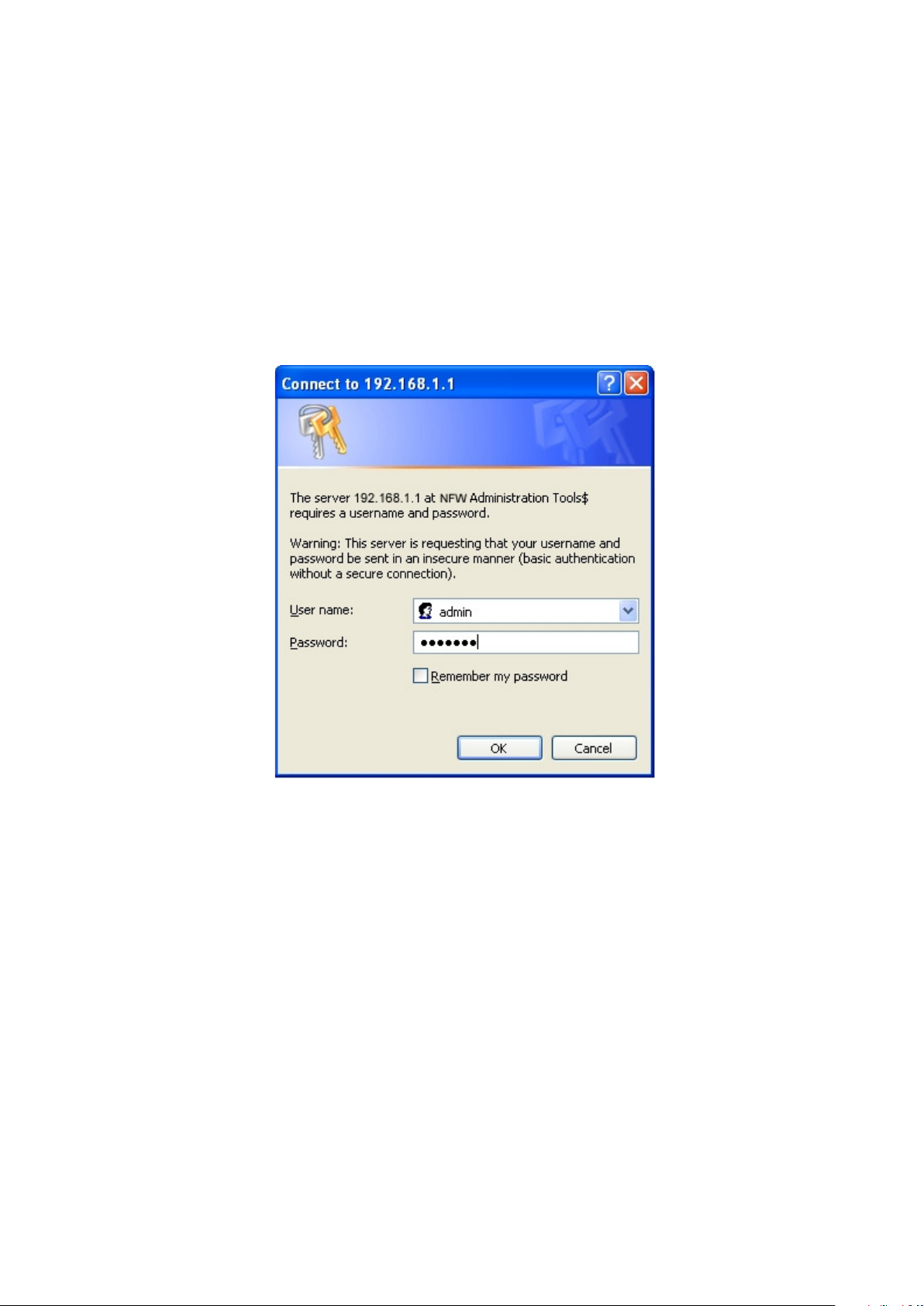
St ep 1 . Connect the IT administrator’s network adaptor and NFW-560’s port1
(LAN1) to the same hub / switch, and then launch a browser (IE or Firefox)
to link the management interface at http://192.168.1.1.
St ep 2 . The browser prompts you for the login credentials. (Both are “admin” by
default. )
(Figure S-1)
Figure S-1 Typing in the User Name and Password

8
St ep 3 . The user interface consists of the following two panels:(Figure S-2)
10.0.0.0 ~ 10.255.255.255
172.16.0.0 ~ 172.31.255.255
192.168.0.0 ~ 192.168.255.255
Menu Panel: Presents all the available system configurations in a tree
directory structure. (See Overview of Functions for further details)
Configuration Panel: Displays the data or configurable settings of the
corresponding item selected on the Menu Panel.
Figure S-2 The NFW-560’s Management Interface
Note:
1. For your reference, you may configure your management address based on the available subnet
ranges below.

9
St ep 4 . At the first login, you will be guided through the basic settings that are
required to install NFW-560 by the wizard. (Figure S-3)
Figure S-3 The Install Wizard
St ep 5 . Select the language and character encoding for your management interface.
(Figure S-4)
Figure S-4 Selecting the Language and Default Character Encoding

10
Important:
1. The default encoding will be applied to the data of unspecified encoding.
Deploying NFW-560 in Gateway Mode
St ep 6 . Configure the LAN settings: (according to your network infrastructure).
(Figure S-5)
Specify the IPv4 Address and Netmask.
Figure S-5 Configuring the LAN Interface Settings
Important :
1. The access to the management interface is subject to the Interface Settings from the Installation
Wizard Step2. Therefore, enter the management address to a Web browser correspondingly if any
change has been made to the default IP address (192.168.1.1).

11
St ep 7 . Configure the WAN Interface (please refer to your ISP for the details).(Figure
)
S-6
Select your Connection Type.
Complete the remaining fields according your network.
Figure S-6 WAN Configuring the WAN Interface Settings

12
St ep 8 . Tick the box of “Synchronize to an NTP server” to ensure the accuracy of
system clock.(Figure S-7)
Figure S-7 Configuring the System Clock Settings
St ep 9 . Configure the wireless network settings.(Figure S-8)
Figure S-8 The Wireless Network Settings

13
St ep 1 0. This step confirms what interface addresses have been assigned to
NFW-560.(Figure S-9)
Figure S-9 Confirmation on Interface Settings
St ep 1 1. Installation is completed after clicking Finish from the previous step.
(Figure S-10)
Figure S-10 Installation Completed

14
Note:
1. After the completion of wizard, an outgoing network policy is created correspondingly under
Policy > Outgoing. (Figure S-11)
Source Address is defaulted to “Inside_Any”.
Destination Address is defaulted to “Outside_Any”.
Service is defaulted to “Any”.
Figure S-11 The Policy Allowing LAN Users to Access External Network Resources
2. To allow Internet access to LAN users, assign their PCs with static IP addresses within the
same subnet as NFW-560 as well as designate NFW-560 as the default gateway. Otherwise,
enable DHCP service to automatically distribute IP addresses to them. LAN traffic can be
regulated by the means of network policies if desired.

15
Deploying NFW-560 in Non-inline Mode
On the existing firewall, specify a LAN subnet 172.19.x.x/16 (with the gateway set to
172.19.1.254)
Place NFW-560 on the LAN behind the firewall.
St ep 6 . Configure the LAN interface as below (using the subnet of 192.168.1.x/24):
(Figure S-12)
Specify the IPv4 Address and Netmask.
Figure S-12 Configuring the LAN 1 Interface Settings

16
St ep 7 . Configure the WAN interface as below (using the subnet of
172.19.20.x/16):(Figure S-13)
Select your Connection Type.
Complete the remaining fields according to your network.
Figure S-13 Configuring the WAN 1 Interface Settings

17
St ep 8 . Tick the box of “Synchronize to an NTP server” to ensure the accuracy of
system clock.(Figure S-14)
Figure S-14 Configuring the System Clock Settings
St ep 9 . Configure the wireless network settings.(Figure S-15)
Figure S-15 The Wireless Network Settings

18
St ep 1 0. This step confirms what interface addresses have been assigned to
NFW-560.(Figure S-16)
Figure S-16 Confirmation on Interface Settings
St ep 1 1. Installation is completed after clicking Finish from the previous step.
(Figure S-17)
Figure S-17 Installation Completed

19
St ep 1 2. Under Network > Interface, set as shown below:(Figure S-18)
Click Modify corresponding to the Port 1.
Select “LAN” for Interface Type.
Select “Transparent Bridging” for Connection Type.
Tick the boxes of “Ping/ Tracert”, “HTTP” and “HTTPS”.
Click OK.
Figure S-18 Configuring the LAN 1 Interface Settings
St ep 1 3. Connect NFW-560’s Port 2 (WAN 1) to your LAN switch or hub and
remove the connection on Port 1 (LAN 1).(Figure S-19)
Figure S-19 The Network Address Settings for Non-inline Mode
Important:
1. The access to NFW-560 is now available through the WAN 1 port only. Therefore, use the address
specified for the WAN interface to access the management interface.
St ep 1 4. Under Network > Interface Group, set as shown below:(Figure S-20)
Select “Group 1” for Port 1 (LAN 1) and Port 2 (WAN 1).
Click OK.

20
Figure S-20 Grouping the Network Interfaces
St ep 1 5. Under AP Controller > Configuration > Settings, configure the
settings under the AP Controller Settings section.(Figure S-21)
Select “Port 1 (LAN 1)” for Connected Interface.
Click OK.
Figure S-21 Configuring the AP Controller Settings
Note:
1. After the completion of wizard, an outgoing network policy is created correspondingly under
Policy > Outgoing, Incoming, WAN to DMZ, LAN to DMZ, DMZ to WAN, DMZ to LAN,
LAN to LAN, DMZ to DMZ.
Source Address is defaulted to “Inside_Any”.
Destination Address is defaulted to “Outside_Any”.
Service is defaulted to “Any”.
2. Wireless clients that are associated with a Nusoft AP may now access the Internet through NFW-560.
To manage the wireless access, please create the needed Policy Objects and apply them to network
policies.

21
Appendix: Product Statement
Any changes or modifications not expressly approved by the party responsible for compliance
could void the user’s authority to operate the equipment.
This device complies with part 15 of the FCC Rules. Operation is subject to the following two
conditions: (1) This device may not cause harmful interference, and (2) this device must
accept any interference received, including interference that may cause undesired
operation.
FCC Radiation Exposure Statement:
This equipment complies with FCC radiation exposure limits set forth for an uncontrolled
environment. This equipment should be installed and operated with minimum distance 20cm
between the radiator and your body.
This transmitter must not be co-located or operating in conjunction with any other antenna or
transmitter.
Note: This equipment has been tested and found to comply with the limits for a Class B digital
device, pursuant to part 15 of the FCC Rules. These limits are designed to provide reasonable
protection against harmful interference in a residential installation. This equipment generates,
uses and can radiate radio frequency energy and, if not installed and used in accordance with
the instructions, may cause harmful interference to radio communications. However, there is no
guarantee that interference will not occur in a particular installation. If this equipment does cause
harmful interference to radio or television reception, which can be determined by turning the
equipment off and on, the user is encouraged to try to correct the interference by one or more of
the following measures:
—Reorient or relocate the receiving antenna.
—Increase the separation between the equipment and receiver.
—Connect the equipment into an outlet on a circuit different from that to which the receiver is
connected.
—Consult the dealer or an experienced radio / TV technician for help.
PRODUCT USAGE RESTRICTIONS: This product is intended for indoor use only.
 Loading...