


Table of Contents
Package Contents ................................................................................................ 2
Deploying as a Fat AP ......................................................................................... 3
Deploying as a Thin AP ...................................................................................... 7
Appendix A: Hardware Installation ................................................................ 13
Appendix B: Power Adapter (Optional) ......................................................... 25
Appendix C: Product Statement ...................................................................... 26
1
Package Contents
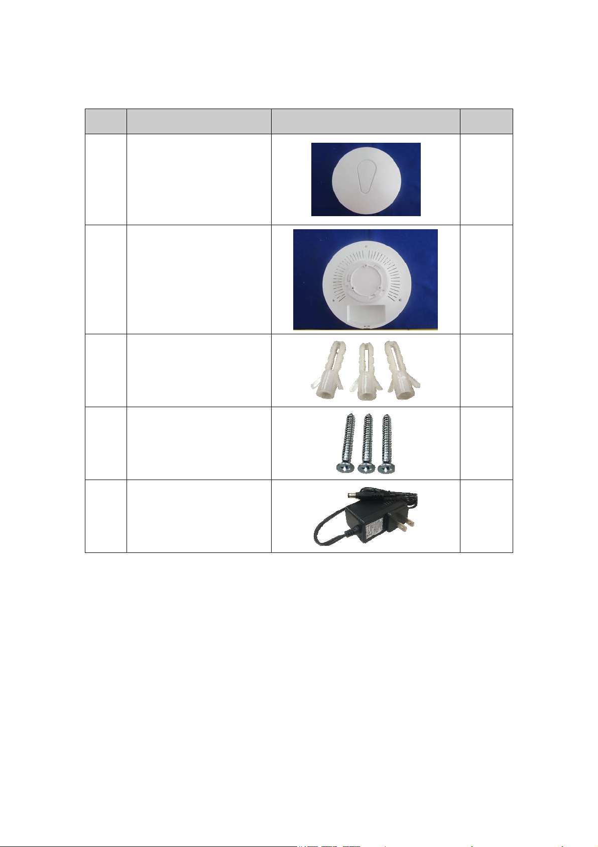
No. Item Image Q’ty
1 NAP-570
2 Mounting Bracket
Plastic Wall Anchors
3
(For ceiling mounting)
Self-Tapping Screws
4
(For ceiling mounting)
1
1
3
3
5
12V / 1.5A Power Adapter
1
(Optional)
2
Deploying as a Fat AP
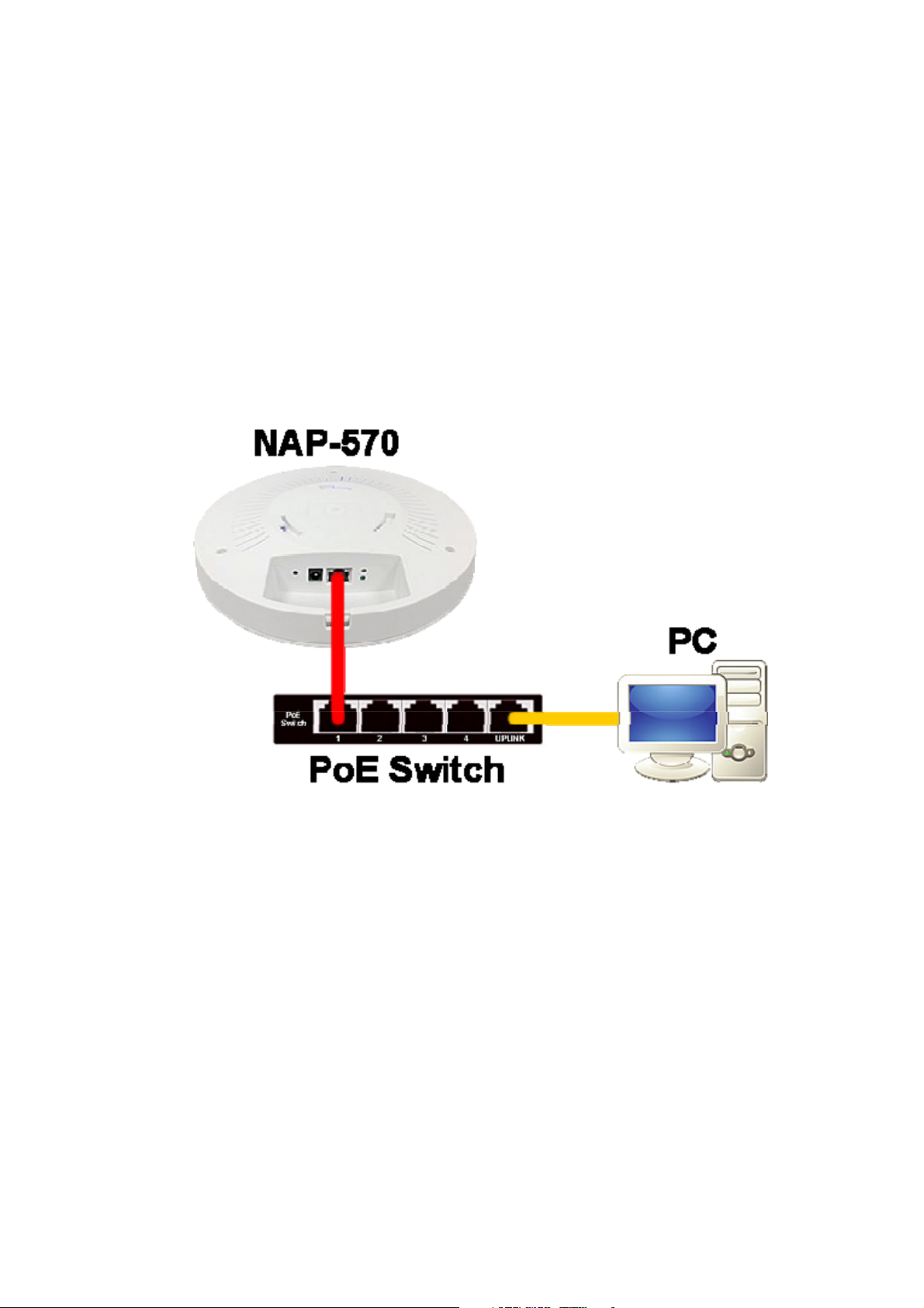
A. Drawing Power from a PoE Switch (If unavailable,
skip to Step B)
1. Connect NAP-570 to a PoE switch (any PoE port that supports
IEEE 802.3at) with an RJ-45 cable, and then connect the Uplink
port of the same PoE switch to the network adapter of a PC
with another RJ-45 cable.
3
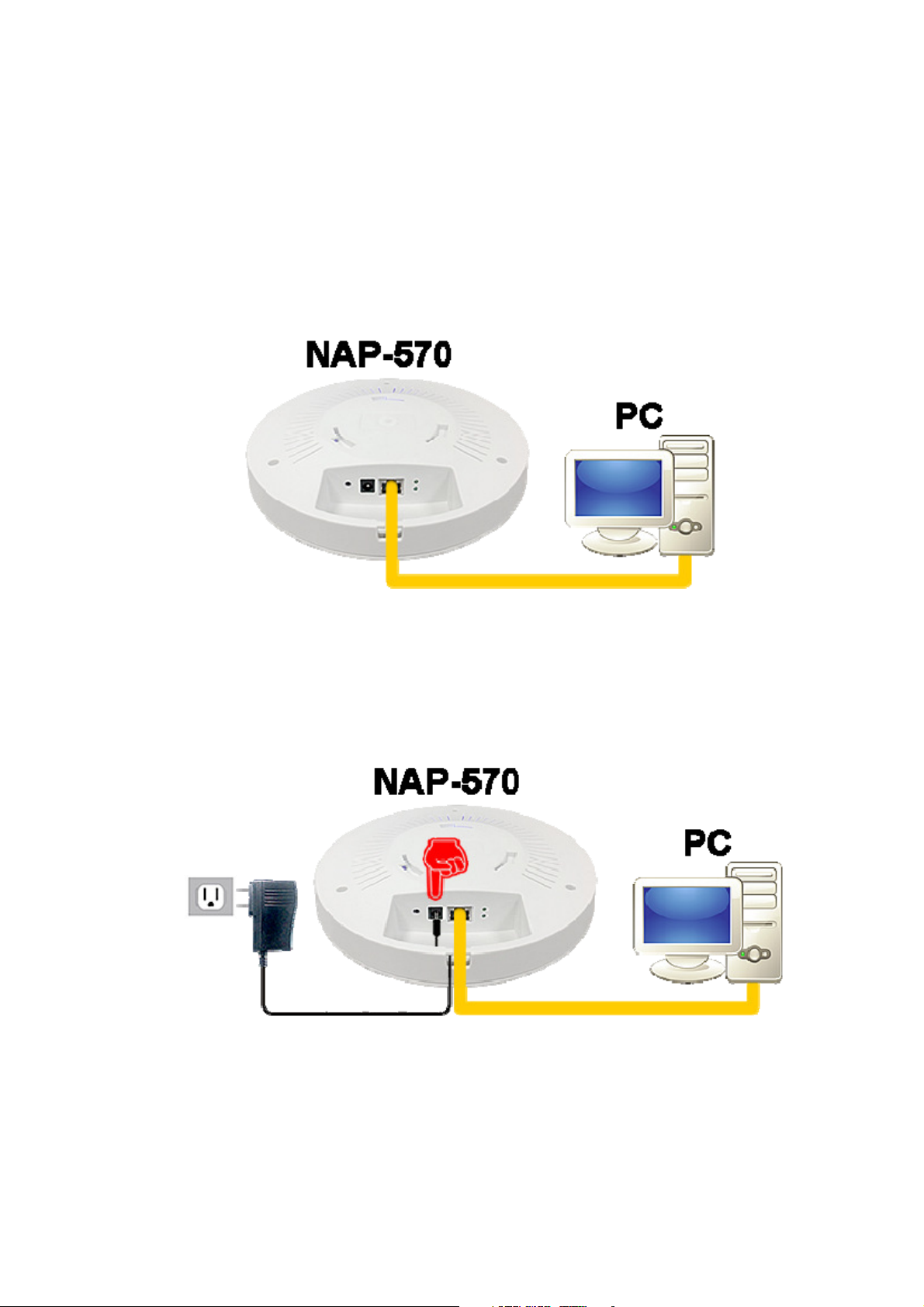
B. Drawing Power from a Power Adapter (Skip this
step if Step A is done)
1. Connect NAP-570 to the network adapter of a PC with an
RJ-45 cable.
2. Connect the DC plug to NAP-570 (Warning: Use of improper
power adapter may cause damage to NAP-570 or lead to
unexpected errors. It is strongly recommended to purchase
the 12V / 1.5A power adapter directly from Nusoft.)
4

3. Plug the power adapter into a nearby wall outlet.
C. Modifying the Management IP Address
1. Run a browser to log in to
management IP address) using the credentials admin /
admin.
2. On the menu panel, click Interface > LAN. Next, select Static
(Manual) from the drop-down list on the configuration panel,
and specify a LAN IP address (not repeatable; this example
uses 192.168.1.10) as well as other information. After that,
click OK.
http://192.168.1.1 (default
5
3. A reboot will be performed for the changes to take effect. Then,
install your AP on the ceiling and re-plug the RJ-45 cable that is
connected to the network adapter of a PC to the LAN.For
instructions on installing the AP, refer to
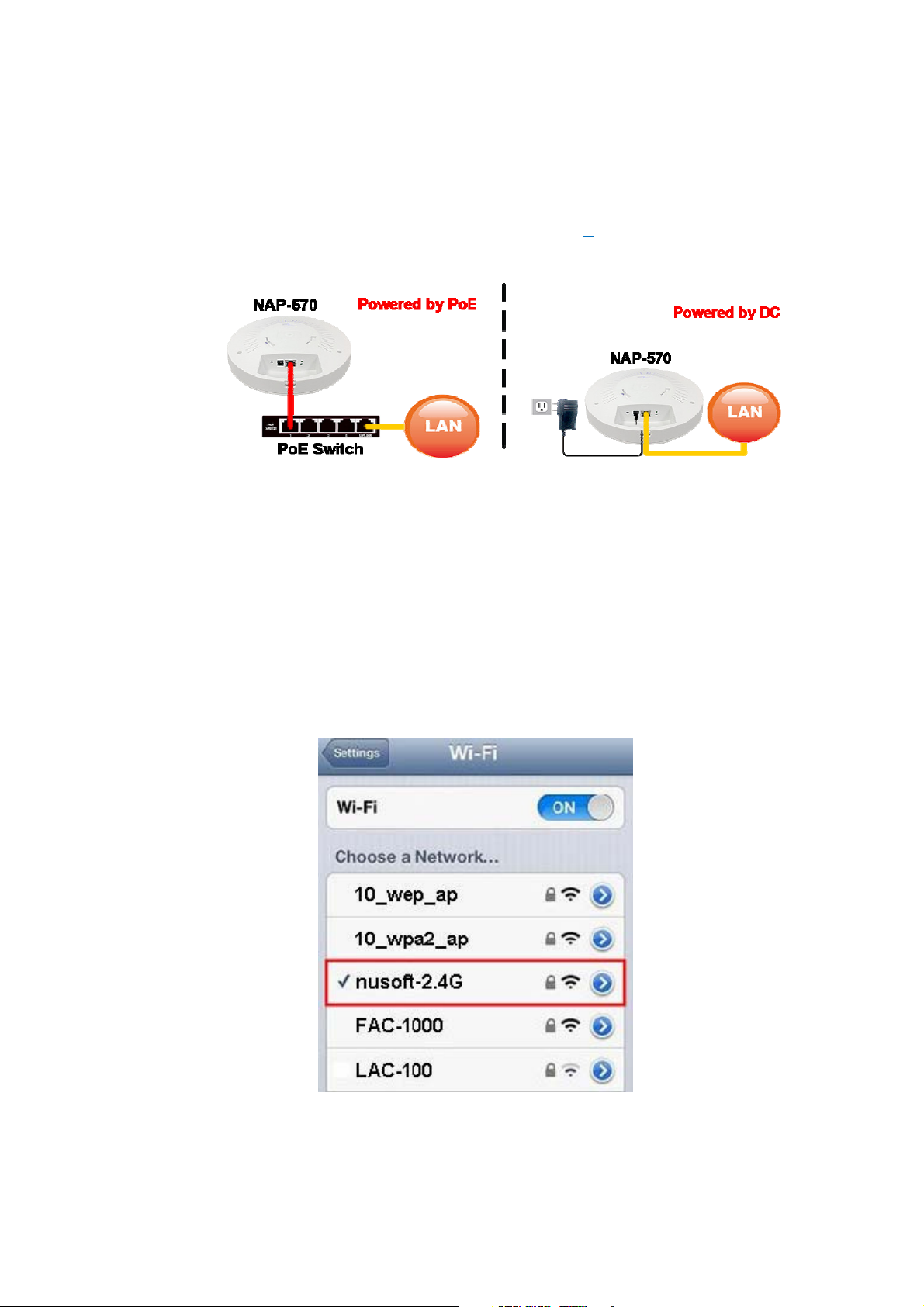
D. Enabling Wi-Fi on a Mobile Device
1. Enable Wi-Fi on your mobile device and then select a default
SSID, i.e.,nusoft-2.4Gornusoft-5G, to access the
Internet. (Note: The 5GHz SSID is only visible to the devices
0
that support 5GHz Wi-Fi.)
6

Deploying as a Thin AP
A. Preparing the LAC-100 AP Controller
1. Configure a PC (requires at least 2GB memory and no hard
disk drive) to boot from a USB device for LAC-100 operation.
2. Refer to
USB flash
LAC-100 USB stick from Nusoft.
3. Boot the PC that is referred in Step 1 from the LAC-100 USB
stick. Once booted, your LAC-100 AP controller is ready to go.
Appendix B: Making an LAC-100 USB Stick
drive (requires at least 8GB) or purchase a pre-loaded
to make a bootable
B. Installing the NAP-570
1. Refer to
keep a note of its MAC address (printed on the product label)
for later use in AP identification and naming.
0 to install your AP at the desired location and then
2. To install a number of APs, it is suggested to draw the power
from an 802.3at PoE switch rather than wall outlets. When
used with the PoE feature, NAP-570 facilitates your wireless
deployment without the restraints of a wall outlet, such as the
length of power cable or the number of the outlet sockets.
7

C. Drawing Power from a PoE Switch (If unavailable,
skip to Step D)
1. Connect NAP-570 to a PoE switch (any PoE port that supports
IEEE 802.3at) with an RJ-45 cable, and then connect the Uplink
port of the same PoE switch to the network adapter of a PC
with another RJ-45 cable.
2. When purchasing a PoE switch, please select a model that is
equipped with sufficient PoE ports for connecting all your
NAP-570 units.
8

D. Drawing Power from a Power Adapter (Skip this
step if Step C is done)
1. Connect NAP-570 to the network adapter of a PC with an
RJ-45 cable.
2. Connect the DC plug to NAP-570 (Warning: Use of improper
power adapter may cause damage to NAP-570 or lead to
unexpected errors.
the 12V / 1.5A power adapter directly from Nusoft.)
It is strongly recommended to purchase
9

3. Plug the power adapter into a nearby wall outlet.
D. Modifying the Management IP Address
1. Connect the network adapters of the LAC-100 and a Windows
PC with an RJ-45 cable (tries a crossover cable in case a
straight-through cable fails). Next, run a browser to log in to
http://192.168.1.1 (default management IP address) using the
credentials admin / admin.
10

2. On the menu panel, click System > Configuration > Interface.
Then, specify a LAN IP address (not repeatable; this example
uses 192.168.1.10) as well as other information. After that,
click OK.
3. Re-plug the RJ-45 cable to the LAN.
11

E. Enabling Wi-Fi on a Mobile Device
1. Enable Wi-Fi on your mobile device and then select the
default SSID (i.e., LAC-100) to access the Internet.
F. Renaming an AP
1. Run a browser on a LAN PC to log in to current management IP
address (modified in Step B). Next, on the menu panel, click AP
Controller > Configuration > AP Profile to rename your AP
(based on the MAC address and installed location, e.g., Lobby)
by clicking the corresponding Modify button.
12

Appendix A: Hardware Installation
Installing on a Drop Ceiling (Suspended
Ceiling)
A. Securing the Mounting Bracket
For ceilings that are made of calcium silicate, plywood,
gypsum board:
1. Prepare the tools needed for the drilling:
Safety glasses
Marking pen
Drill driver (or a #2 Phillips screwdriver)
2. Put on safety glasses for eye protection
3. Mark the pilot holes
a. Use the mounting bracket as a drill template to
mark the pilot holes on the ceiling.
4. Secure the self-tapping screws
a. Hold the mounting bracket as per picture
shown and then align the holes with the marks.
13

Next, secure the bracket with the screws (drilled
at 90° one at a time) using a drill driver or a
screwdriver.
B. Whether your NAP-570 units are drawing power from a PoE
switch or a power adapter, please route the cable(s) through the
access hole as per picture shown. (Warning: Drawing power from
a PoE switch and a power adapter “at the same time”
damage to NAP-570 or lead to unexpected errors.)
may cause
C. Hold the unit bottom side up and position the ports in the same
direction as the triangle icon indicates on the mounting bracket.
Align the grooves with the latches and then lift up and rotate the
unit clockwise until you hear a “click” sound.
14

Installing on a Hard Ceiling
A. Securing the Mounting Bracket
For ceilings that are made of cement or other solid
substances:
1. Prepare the tools needed for the drilling:
Safety glasses
Marking pen
Steel nail
Claw hammer
Drill driver (with a hammer-drill setting)
6mm masonry bit
#2 Phillips screwdriver
2. Put on safety glasses for eye protection
3. Mark the pilot holes
a. Use the mounting bracket as a drill template to
mark the pilot holes on the ceiling.
15

4. Drill the mounting holes
a. Hold the nail against the marks (one at a time)
and tap it with the hammer to leave a small
dent.
b. Mark the length of plastic wall anchor on the
masonry bit.
c. For drilling on ceramic tile, make sure the
hammer-drill setting is not used until the tile is
drilled through.
16

d. Keep the masonry bit at 90° to the wall and start
drilling till the hole is as deep as the mark. (Do
not press the trigger continually as the drill
motor may be damaged due to overheating.)
5. Tap in the plastic wall anchors with the claw
hammer.
6. Secure the mounting bracket with the self-tapping
screws.
17

B. Whether your NAP-570 units are drawing power from a PoE
switch or a power adapter, please route the cable(s) through the
access hole as per picture shown.
a PoE switch and a power adapter “at the same time”
damage to NAP-570 or lead to unexpected errors.)
(Warning: Drawing power from
may cause
C. Hold the unit bottom side up and position the ports in the same
direction as the triangle icon indicates on the mounting bracket.
Align the grooves with the latches and then lift up and rotate the
unit clockwise until you hear a “click” sound.
18

Appendix C: Power Adapter (Optional)
Caution: Prior to use, make sure your NAP-570 unit is powered by a
proprietary power adapter (see the specs below).
Specifications:
• AC input: 100-240V, 0.4A @ 50 / 60 Hz
• DC output: 12V / 1.5A, 18W max.
25

Appendix D: Product Statement
FCC Compliance Statement:
This equipment complies with part 15 of the FCC Rules. Operation is subject to
the following two conditions: (1) This equipment may not cause harmful
interference, and (2) this equipment must accept any interference received,
including interference that may cause undesired operation.
Warning: Any changes or modifications not expressly approved by the party
responsible for compliance could void the user's authority to operate the
equipment.
This equipment has been tested and found to comply with the limits for a Class
B digital device, pursuant to part 15 of the FCC Rules. These limits are
designed to provide reasonable protection against harmful interference in a
residential installation. This equipment generates, uses and can radiate radio
frequency energy and, if not installed and used in accordance with the
instructions, may cause harmful interference to radio communications.
However, there is no guarantee that interference will not occur in a particular
installation. If this equipment does cause harmful interference to radio or
television reception, which can be determined by turning the equipment off and
on, the user is encouraged to try to correct the interference by one or more of
the following measures:
-Reorient or relocate the receiving antenna.
-Increase the separation between the equipment and receiver.
-Connect the equipment into an outlet on a circuit different from that to which
the receiver is connected.
-Consult the dealer or an experienced radio / TV technician for help.
FCC Radiation Exposure Statement:
This equipment complies with FCC radiation exposure limits set forth for an
uncontrolled environment.
distance 20cm between the radiator& your body
This equipment should be installed and operated with minimum distance 20cm between the radiator& your bodyThis equipment should be installed and operated with minimum
This transmitter must not be co-located or operating in conjunction with any
other antenna or transmitter.
Usage Restrictions: This equipment is intended for indoor use only.
26
 Loading...