

Page 1

Page 2
Operating Manual
INTRODUCTION - SuperCut 2000
Thank you for purchasing the new SuperCut 2000 NT Nursery Trimmer from
Nursery Supplies Australia Pty. Ltd.
The SuperCut 2000 is a machine for pruning and harvesting plant material. It can
be used in the Plant production, Forestry, Horticultural and Agricultural industries.
It is designed to be operated by three trained people.
The machine should only be used on plants with a stem diameter of 7mm or less.
SAFETY ALERT SYMBOLS & NOTATIONS
The following safety notations are used in these Operating Instructions. Read and
understand the message in each notation and be alert to unsafe conditions and
the possibility of personal injury.
Symbol Type of Warning
NOTE Points out general reference information regarding proper
operation and maintenance practices
IMPORTANT Indicates specific procedures or information that is required to
prevent damage to the machine or attachments
CAUTION Identifies safe operating practices or indicates unsafe
conditions that could result in personal injury.
WARNING Describes a condition where failure to follow the instructions
could result in severe personal injury
DANGER Designates a condition where failure to follow instructions or
heed warning will most likely result in serious personal injury or
death
IMPORTANT SAFETY INFORMATION
WARNING
• These instructions convey important information on the safe operation and
maintenance of the SuperCut 2000 NT. This machine can cause serious
injuries. Read the Operating Instructions carefully for the correct handling,
preparation, maintenance, starting and stopping of the machine; be familiar
with all controls and the proper used of the machine.
• Never allow children to use the machine
• Avoid operating while people, especially children are nearby
• Never climb on a ladder while operating the machine.
• Never use the machine alone
• Always ensure all handles and guards are fitted when using the machine.
Never attempt to use an incomplete machine or one fitted with an
unauthorised modification
• When transporting or storing the machine always fit the cutting device guard.
CONTENTS
INTRODUCTION - SUPERCUT 2000 1
SAFETY ALERT SYMBOLS & NOTATIONS 1
IMPORTANT SAFETY INFORMATION 1
Occupational Health and Safety 2
NOISE AND VIBRATION LEVELS 2
MODEL AND SERIAL NUMBERS 3
CUSTOMER SERVICE/WARRANTY 3
SAFETY AND WARNINGS 4
Before Operating 4
Safe Operation of the SuperCut 2000 NT 4
Limitations and Restrictions 5
Safe Operation 5
Protective Clothing 5
Supercut 2000NT Nursery Trimmer - Controls 6
Fuel & Oil 7
Filling the Fuel Tank 7
STEP BY STEP OPERATION 8
Starting 9
Stopping 10
Installation of Collection Bag 10
Removal of Collection Bag 10
Replacing the Drive Belt 10
Adjusting handles 11
MAINTENANCE 11
Oiling Cutting Blades 11
Greasing Crank Case 11
Setting and Adjustment of Cutting Blades 12
Check the adjustment of blades 12
Adjustment and Cleaning of Blow-duct. 12
Cleaning of Blower 12
Cooling Fins 13
Carburettor Adjustment 13-14
PLANT HYGIENE 15
ROUTINE MAINTENANCE 15
After Each Use 15
Sharpening Cutting Blades 15
TRANSPORT & STORAGE 16
Long Term Storage 16
Removal from Storage 16
MAINTENANCE CHECKLIST 16
TROUBLESHOOTING 17
SPECIFICATIONS 17
1
Page 3
Operating Manual
2 3
IMPORTANT SAFETY INFORMATION
OCCUPATIONAL HEALTH AND SAFETY
Nursery Supplies Australia Pty Ltd recommend that all new and potential users of
the SuperCut 2000 NT be aware of Occupational Health and Safety Requirements
pertaining to their own country, and use this Trimmer in accordance with those
regulations.
NOISE AND VIBRATION LEVELS
The following data relates to the SuperCut 2000 Nursery Trimmer under normal
operating conditions.
Noise Levels
The Supercut 2000NT Nursery Trimmer has been tested for noise levels measured
at the ear of the operator at the engine end, with blades engaged and engine at
two speeds.
Sound pressure level at workstation
High level recorded = 98,9 dBA @ 8100 RPM
High level recorded = 95,1 dBA @ 7000 RPM
Peak instantaneous sound pressure = 112,5 dBC @ 8100 RPM
Sound Power Level measured = 110,3 dBA @ 8100 RPM
Based on measurements of identical machines per international standard testing
procedures
WARNING
Nursery Supplies Australia Pty Ltd therefore recommend that all persons operating
the Supercut 2000NT Nursery Trimmer ensure that they make use of hearing
protection devices at all times.
Vibration Levels
The Supercut 2000NT Nursery Trimmer has also been tested for Vibration.
Recorded Levels and locations are as follows:
handlebar on engine side = 7,5 m/s2 @ 8120 RPM
handlebar on accelarator side = 6,1 m/s2 @ 8120 RPM
handlebar on engine side = 6,7 m/s2 @ 7020 RPM
handlebar on accelarator side = 3,6 m/s2 @ 7020 RPM
Based on measurements of identical machines per international standard testing
procedures
MODEL AND SERIAL NUMBERS
The model and serial numbers are located on the body of the
Trimmer above the cutting blades.
CUSTOMER SERVICE AND WARRANTY
Use only genuine spare parts for your SuperCut 2000 NT. When ordering spare
parts, contact Nursery Supplies Australia Pty Ltd or authorised agent with the
model and part details.
The model & Serial number will need to be recorded and quoted to the supplier in
the event of a service issue For easy reference, the following table will assist to
record the correct model information at time of purchase. or query and when
ordering spare parts.
Model No: V8NEWZ2 or V8XHD
Serial No:
Date of Purchase
WARRANTY
The manufacturer warranties Supercut 2000NT for 12 months against faulty
manufacture or failure of original parts when operated according to these
instructions. The warranty does not cover replacements required as a result of fair
wear & tear or as a result of unauthorised modification, or operator negligence.
The warranty covers replacement parts only & does not cover labour costs.
Please retain this manual for future reference.
This manual also explains the necessary information for the correct operation of
Zenoah/Komatsu engines fitted to Supercut 2000NT Nursery Trimmer distributed
by Nursery Supplies Australia Pty Ltd or Authorised Agent.
Please refer to Nursery Supplies Australia Pty. Ltd. for information concerning
problems not described in this manual and for replacement parts.
SERIAL NUMBER
Page 4
4
SAFETY AND WARNINGS
BEFORE OPERATING
DANGER
Never allow children to use or be near the Trimmer while it is operating.
WARNING
Carefully inspect the area where the Trimmer is to be used and remove
any objects, which may be damaged or thrown by the Trimmer in operation.
IMPORTANT
• Read the Operating Instructions to familiarise yourself with the components
of the SuperCut 2000 NT and its use.
• Check the Trimmer carefully for loose screws, bolts, and
damaged or broken parts.
• If necessary, replace parts or make necessary repairs. Check if blades
need sharpening.
• Inspect the plants to be trimmed for hidden wires, posts, stakes or other
rubbish that may damage the blades.
NOTE
Be familiar with all controls and safety warnings.
SAFE OPERATION OF THE SUPERCUT 2000 NT
WARNING
• Dress properly. Do NOT wear loose clothing or jewellery which can be
caught in moving parts. Use sturdy gloves, non-skid footwear, ear protection
& safety glasses
• Do not operate the Trimmer holding it above waist height.
• Keep your hands and body away from the blades at all times.
• Never leave the Trimmer unattended to prevent unauthorised use.
• Store the Trimmer safely out of the reach of children.
• The engine & blades of the Supercut 2000NT Nursery Trimmer get hot with
continuous use. Do NOT place hands or any body part near or on potentially
hot surfaces.
NOTE
Work slowly and deliberately. Plan your cutting before starting the machine.
DANGER
• Petrol is highly flammable
• Store fuel in containers specifically designed for petrol.
• Refuel outdoors only. (see section titled "Filling the Fuel Tank")
• Do not smoke while operating or refuelling.
• Add fuel before starting engine. Never remove the cap of the fuel tank while
the engine is running or hot.
SAFETY AND WARNINGS
LIMITATIONS AND RESTRICTIONS
The SuperCut 2000 NT has been specifically designed for the pruning of branches
of plants.
IMPORTANT
a) Do not use the Trimmer to cut material with a diameter of more than 7mm.
This may cause damage to the blades and / or transmission.
b) Do not operate the Trimmer near ground level (eg. for weeds and lawns). This
may cause damage to blades by soil, sand and pebbles. Stones being
thrown up by the Trimmer may also cause injury to people and damage to
property.
c) Do not use the Trimmer for uses other than those outlined in the Operating
instructions.
WARNING
Turn OFF the engine before doing any of the following:
a) Changing and adjusting blades, oiling and cleaning blades, repairing around
the blades and blower.
b) Installing and changing the collection bag.
SAFE OPERATION
WARNING
a) Do not operate the SuperCut 2000 NT in a confined space or indoor where
dangerous fumes can collect. If using this machine inside a Glasshouse or
Tunnelhouse, all available doors, vents & exhaust systems should be opened.
If this is not adequate - move the plants outside for pruning.
b) Operate only in daylight or in good artificial light.
c) Ensure cutting blades are disengaged before starting the engine.
d) Disengage cutting blades and close throttle before turning off the engine.
PROTECTIVE CLOTHING
WARNING
The Supercut 2000NT Nursery Trimmer has a petrol driven engine and fast
reciprocating blades. The engine can be noisy when operating and the blades can
cause serious injury. Dress properly. Do not wear loose clothing or jewellery that
can be caught in moving parts.
Use safety glasses, ear protection sturdy gloves & non-skid footwear.
5
Operating Manual
Page 5
6
SAFETY AND WARNINGS
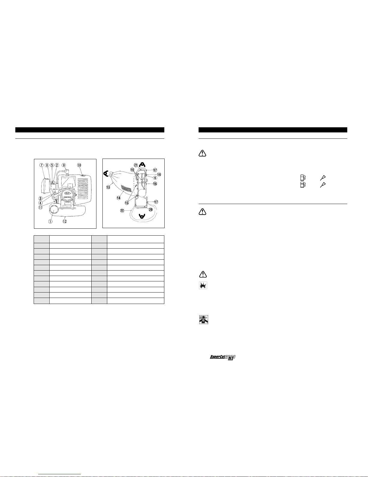
SUPERCUT 2000NT NURSERY TRIMMER - CONTROLS
It is recommended that operators become thoroughly familiar with the following
controls and components of the SuperCut 2000 NT.
SAFETY AND WARNINGS
FUEL & OIL
The SuperCut 2000 NT has a TWO-STROKE ENGINE.
IMPORTANT
• It is recommended that the operator use regular grade UNLEADED fuel with
two-stroke oil.
• Only use oil designed for Air Cooled, 2 Stroke motors
For the first
20 hours of operation run at
20
: 1 mixture
After
20 hours of operation run at 25 : 1 mixture
FILLING THE FUEL TANK
WARNING
Shut the engine off and place the SuperCut 2000 NT on level ground.
Clean around the fuel tank cap and remove the cap. Use a funnel and add
the pre-mixed FUEL/OIL mix to 6mm below the bottom of the filler neck.
Do not fill the tank completely.
Fasten the fuel tank cap securely. Wipe up or wash away any fuel that may have
spilled.
Ensure no dust or other contaminants get into the fuel tank.
DANGER
Petrol is highly flammable.
Do not smoke while operating or refuelling.
Add fuel before starting engine. Never remove the cap of the fuel tank while the
engine is running or hot.
Store fuel in containers specifically designed for this purpose
Store the unused fuel in airtight container in a dark and cool places Fuels
deteriorate through long exposure to ultraviolet rays or excessive heat, resulting in
failure to start and/or low power.
Refuel outdoors only
7
Operating Manual
Part No: Part / Component Part No: Part / Component
1 Fuel Cap 12 Fuel Tank
2 Choke 13 Collection Bag
3 Primer Pump 14 Collection Bag Vent (to top)
4 Zip Cord Handle 15 Bag attachment points
5 Idle Screw 16 Blower
6 17 Handle
7 Air Cleaner 18 Handle Adjustment Points
8 Carburettor 19 Throttle
9 Spark Plug (Cover) 20 Hold to Run Control Engine Stop
10 Muffler 21 Hold to Run Control Blade Clutch
11 Fuel line 22 Harness
operator A
operator C
operator B
Page 6
8
STEP by STEP OPERATION
STARTING
COLD STARTS
A. Place Supercut 2000NT on clear level
ground.
B. Remove blade protector.
C. Pour the fuel into the tank and fasten the
cap tightly.
D. Pump fuel into the carburettor by pressing
the primer pump until fuel is visible in bulb.
E. Set the throttle lever at the idling
(lowest) position.
F. Ensure both Kill switch & Hold to run
control are in the “Run” position.
G. Swing the choke located at the top of
the carburettor toward the engine to start.
H. Turn off choke as engine begins to roughen.
You cannot set the Choke at the starting position unless the throttle lever is in the idle
position.
WARM STARTS
You can restart the engine immediately after operation with the Choke “Off”.
STARTING
Put the machine on flat stable ground, and pull the zip cord with one hand and use the
other to grip the Engine Stop Hold-to-run control and support the machine.
1. Pull the zip cord slowly at first and then as you feel the resistance pull quickly for
the rest of the action.
IMPORTANT
2. DO NOT pull the cord out completely. Do not let the zip cord go. Let it retract
slowly.
3. Ensure that the throttle lever remains at the idling position during warming up.
4. If you increase the throttle lever when the engines is not warm enough, the choke
will automatically set back at the operating position and it may stop the engine
5. Allow machine to warm up for 2 minutes before cutting
6. Increase engine speed before commencing cutting.
7. Reduce throttle to idle when not cutting.
8. When in position to begin cutting, engage the cutting blades by Operator A
gripping the Hold to Run Control on the throttle lever end. Always fully engage
the blades & only do this when the engine is running.
ACTIVATING THE CUTTING BLADES
9. To disengage the cutting blades, operator A should release the Hold to Run
Control on the throttle lever end.
STEP by STEP OPERATION
The Supercut 2000NT Nursery Trimmer is designed to be operated by three (3)
trained persons.
WARNING
a) Once the Trimmer and its components have been inspected for safety and the
Collection Bag has been installed, the SuperCut 2000 NT is ready to be used.
b) Carefully inspect the area to be cut and remove any objects which may be
damaged or thrown up by the Trimmer.
c) Operator B should grip the Hold to Run control on the handle at the engine end
& pull the starter cord to start the engine.
d) Operator A should adjust the throttle to the engine speed that best suits the
type of plant being cut. Some experimentation with engine speed may be
required to establish the most economical level for each plant type. Having the
throttle fully open at the highest engine speed provides the best cut and
collection method. However, high engine speed will consume more fuel and
decrease engine life.
e) The handle at the engine end is provided with a sling type harness which
should be adjusted to fit over the operators shoulder to support the weight of
the trimmer & reduce muscular strain.
f) Operator A can engage the blades (by gripping the Hold to Run control at the
non engine end) when ready to commence cutting.
NOTE
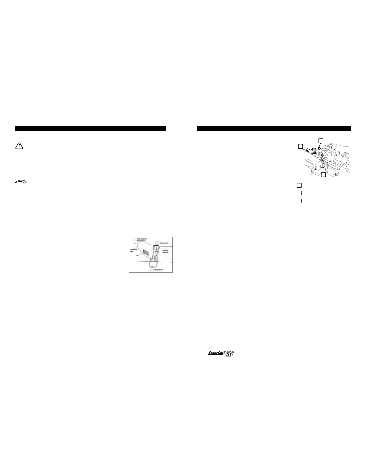
g) The Trimmer requires 3 operators. Operator B (on the
engine end) should proceed slightly behind operator A
on the throttle lever end. This allows operator C to
follow operator A & support the collection bag to
prevent it dragging across the cut plants.
h) Both operators A & B control the cutting height - some
practice may be necessary to ensure a flat, even cut.
i) With the Trimmer raised to the correct height for the
plant, walk at an even pace down the row of plants to
be cut.
CAUTION
j) The bag will become heavy with prunings & will require emptying when filled.
The ergonomic posture of each user and the weight of prunings have the
potential to result in muscular strain. Nursery Supplies Australia P/L therefore
recommend that the 3 users rotate positions every 10 minutes of operation, to
reduce such risk.
k) Shut off the engine and remove cuttings from the Collection Bag as required. If
the Collection Bag becomes too heavy the Trimmer will be difficult and
dangerous to operate.
IMPORTANT
l) If pruning larger or higher plants two or more cutting runs may be required.
Do not attempt to remove excessive amounts of foliage on the first pass and
never cut stems greater than 7mm in diameter.
9
Operating Manual
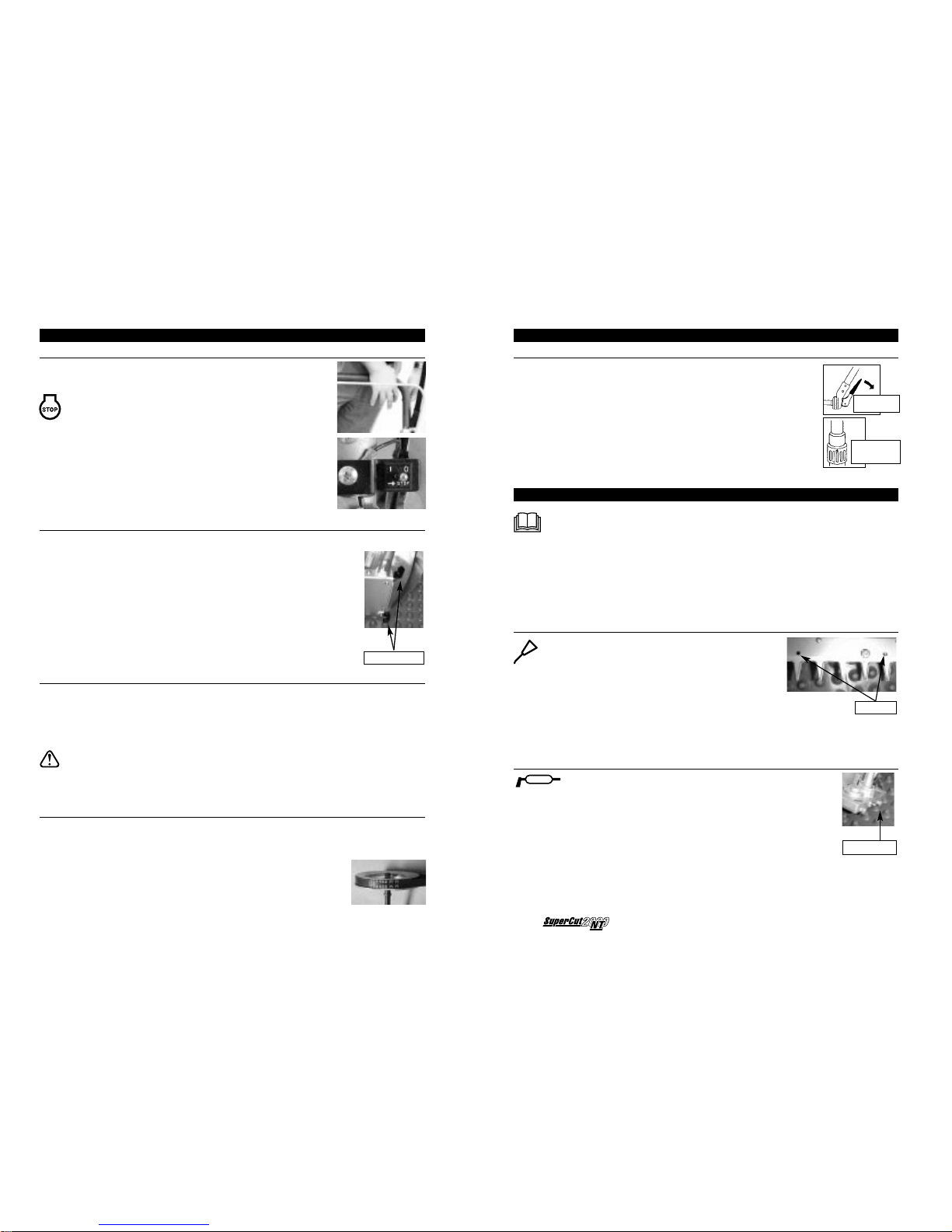
Choke ‘On’ position
Choke - Operating Position ‘Off’
Primer Pump
3
2
1
1
2
3
Page 7
10
STEP by STEP OPERATION
ADJUSTING HANDLES
For safety and optimum performance the handles on either side
of the Supercut 2000NT Nursery Trimmer should be adjusted
to suit each individual user.
• Locate the handle adjustment on either side of the
Trimmer.
• Release the handles and adjust the angle and length so
the Trimmer is comfortable and easily controlled. The
ratchet allows for height adjustment and the slide clamp
allows for length adjustments.
MAINTENANCE
IMPORTANT
• Regular and on going maintenance of your SuperCut 2000 NT will ensure
optimal performance and lifespan. The supplier recommends major services
be performed by a reputable Service Mechanic.
• Stop the engine & remove the spark plug lead before attempting any
maintenance or repair work.
• Refer to the Maintenance Checklist for recommended service intervals.
OILING CUTTING BLADES
• Locate ALL oil points on the blades and using
an oiling can, place several drops of oil into each
of the holes.
• Start the engine, engage the blades to distribute
the oil and then disengage blades and turn off
engine.
• Remove excess Oil.
• It is recommended that the blades be oiled after every 1 hour of operation
and at the end of each session where plants are wet.
GREASING CRANK CASE
• Locate Grease nipple on the transmission housing
IMPORTANT
• Using a grease gun, apply grease to the grease nipples until
the old grease begins to be expelled from near the blades.
• Use only Rocol Sapphire HI-TEMP 2 (or equivalent
specification - NLGI no.2, -40°C to 200°C
STEP by STEP OPERATION
STOPPING
10. Disengage the cutting blades by operator A releasing
the Hold to Run control.
11. Push throttle lever anti-clockwise to OFF point.
EMERGENCY
STOP
12. Release the Engine stop Hold to Run Control or
switch the Off Button/Kill Switch to the "O" position,
to stop the engine.
CAUTION
13. Always ensure that the engine is turned off and the
blades are disengaged before placing the SuperCut
2000 NT down on the ground.
INSTALLATION OF COLLECTION BAG
NOTE
• Keep the net section of the bag to the top.
• Locate a 'buttonhole' opening on the middle of the elastic
hem and attach this onto the upper middle hook of the
frame. The elastic hem should be clipped over all six (6)
hooks working from one side of the Trimmer to the other.
Note that the lower half should be mounted between the
aluminium plates.
• Tie up the open end of the bag.
REMOVAL OF COLLECTION BAG
• Turn off the engine.
• Place the Trimmer onto level ground.
• Carefully remove the bag from the hooks on the frame.
• Untie the bag and remove cuttings.
• Replace the bag if required.
WARNING
• Never attempt to install or remove Collection Bag while the engine is
operating and/or the cutting blades are engaged.
REPLACING THE DRIVE BELT
• If inspection finds the Drive Belt is worn, frayed or slipping remove the
guards and release the blade clutch cable from the tension pulley.
• The Drive Belt should be loose enough to remove from the engine pulley and
drive shaft pulley.
• Fit new belt (M19 for V8NEWZ2 or M18 for V8XHD)
• Reposition tension pulley and refit the blade clutch cable.
• Refit guard
11
Operating Manual
PUSH DOWN
TO ADJUST
TURN TO
ADJUST LENGTH
OF HANDLE
OIL POINTS
GREASE NIPPLE
ATTACH BAG HERE
Page 8

12
MAINTENANCE
SETTING AND ADJUSTMENT OF CUTTING BLADES
IMPORTANT
The fast, reciprocal movement of the blades can cause blades
to lose their adjustment. If the quality of cutting is reduced,
some adjustment of the blades may be necessary. Adjustments
are made as follows:
• Whilst holding the screw (2) on the bottom of the blades,
loosen nut (1) off completely. Use the special tool and
screwdriver supplied.
• Re-tighten the nut fully and then turn back 1/2 to
3/4 turn so the blades will move freely.
• Repeat for all other nuts on the blades.
• Oil the blades after adjusting the nuts and bolts.
CHECK THE ADJUSTMENT OF BLADES
To check the adjustment of the nuts and bolts on the blades:
• Start the engine and engage the blades. Run the Trimmer at the highest
possible speed for approximately one minute. Disengage the blades and turn
off the engine.
• If the nuts on the cutting blades are warm to touch, adjustment and
clearance is correct. If the nuts are hot to touch, they are too tight and need
to be loosened 1/3 to 1/2 turn.
• Repeat steps 1 + 2 above.
ADJUSTMENT AND CLEANING OF BLOW-DUCT.
The Blow-duct will not require adjustment under normal
conditions of use. The direction of the outlets on the frame
is crucial to the way the cuttings are blown into the bag.
The openings on the blower should remain free from
blockages.
If the Blow-duct direction is not correct then optimal
performance pick-up of cuttings will not occur.
1. Loosen off screws on the base of the duct and rotate duct back into the
correct position.
2. Re-tighten screws.
CLEANING OF BLOWER
If performance of blow-duct is noticeably reduced, it could be due to a blockage
or debris build up on the fan air intake.
1. With engine off, carefully clean the area on the fan cover of any dust or debris
with a soft brush.
WARNING
2. Do not insert anything into the Air Intake when engine is running as the
rotating parts may cause personal injury or result in damage to the machine.
MAINTENANCE
COOLING FINS
Inspect the engine cylinder cooling fins before each operation & remove any debris
which may clog the fins. When cooling fins are clogged, the engine may overheat
resulting in breakdown.
CLEANING OF AIR FILTER
A. Remove dust inside the air filter cover after every 25-hours of operation.
(more often in Dusty conditions). To open the air filter, press the hook to
detach the air filter cover.
B. If the element is heavily soiled, clean it thoroughly with petrol and dry it well.
C. Check internal surfaces of body & Carburettor intake throat & ensure no dust
or debris is present. Reinsert air filters
D. If the element is deformed or damaged, replace it with new one. Refer to
Nursery Supplies Australia Pty Ltd or Authorised Agent for replacement
parts.
IMPORTANT
A clogged or damaged air-cleaner element may lead to the reduction of engine
performance.
Do not operate the engine without element or with deformed or damaged element.
This can damage the engine.
CARBURETTOR ADJUSTMENT
TENSION OF THE THROTTLE CABLE
One to two millimetres of clearance is appropriate with the throttle lever at the idle
position. You can adjust the clearance by loosening or tightening the throttle cable
adjustment nut located at the upper side of the carburettor.
13
Operating Manual
Air filter elements (X2)
Cover Hook
Air filter cover
Air filter body
4
3
2
1
1
2
3
4
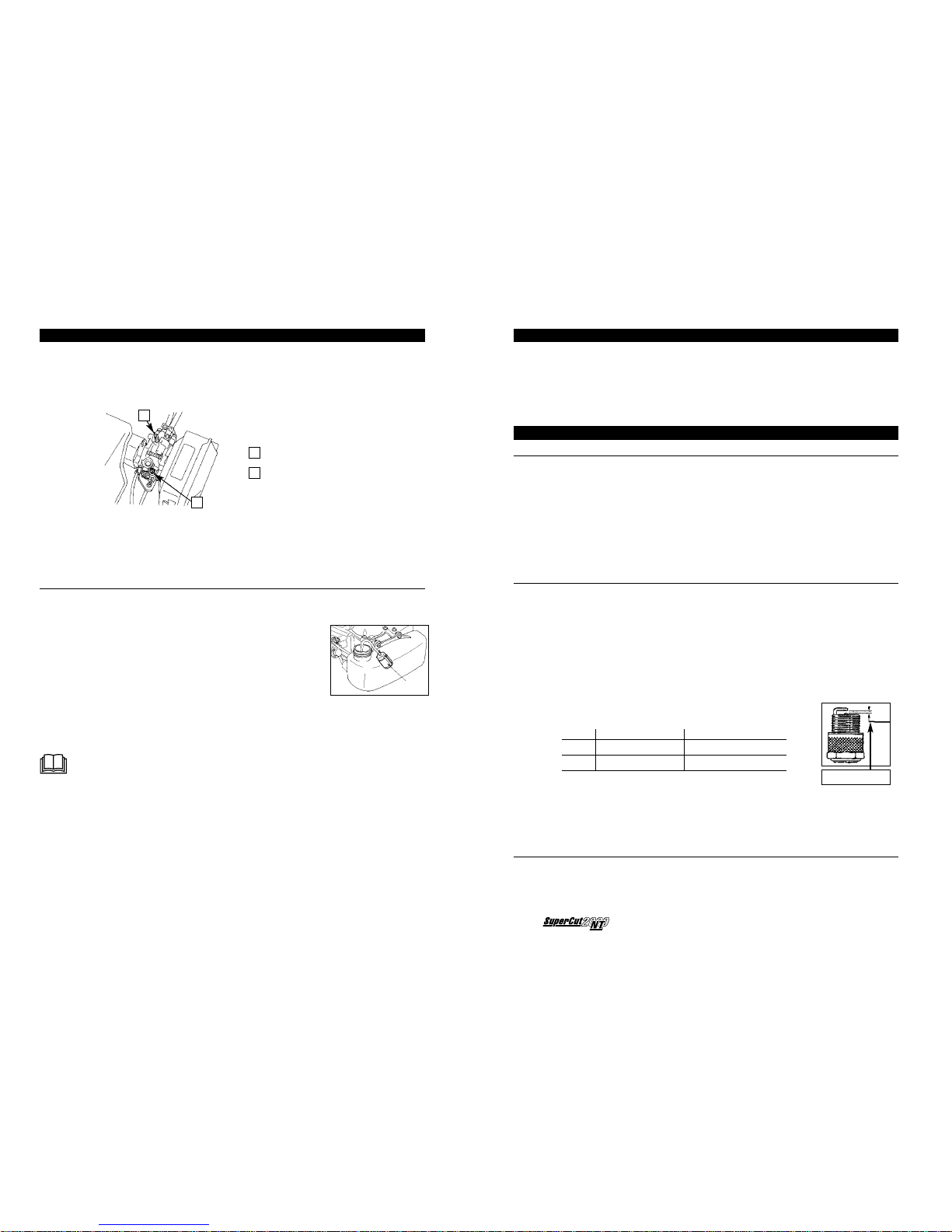
Throttle Cable Tension Nut
High Speed Mixture Adjuster Screw
2
1
1
2
1-2mm
1. ADJUSTMENT NUT
2. ADJUSTMENT SCREW
3. WASHER
Page 9
Operating Manual
14 15
MAINTENANCE
IDLING SPEED
IMPORTANT
These screws are set at the factory & should not require adjustment.
It is best to refer this type of adjustment to an experienced mechanic.
Adjust the engine speed at idle by turning the idle adjustment screw. If the engine
stops or the engine speed is too high, amend adjustment as required.
To increase the idle rpm, turn the screw to the right, and to reduce, turn the screw
to the left.
FUEL TANK AND FUEL FILTER
Inspect the inside of the fuel tank after every 25 hours operation. If dust or
moisture is found, remove the tank from the machine and clean it thoroughly.
Dry well and replace.
To clean the fuel filter, empty the fuel tank and then
take out the fuel filter.
If the filter is clogged up, replace it with new one. Refer to
Nursery Supplies Australia Pty Ltd or Authorised Agent for
replacement.
FUEL TANK CAP
Inspect the air vent, and if it is clogged up, take the cap off and carefully dislodge
dust using a soft wire. Take care to avoid contaminating fuel in tank.
IMPORTANT
Clogging of the fuel filter or the air vent can cause low power or sub-standard
engine performance.
Do not operate the engine without the fuel filter. Sediment may enter the
carburettor and may cause damage to the engine
PLANT HYGIENE
In order to reduce the risk of spreading disease, it is recommended that the
cutting blades of the Supercut 2000NT Nursery Trimmer be sterilised after each
row of plants, or between cutting of different species plants. The sterilising
solution used for your pruning equipment should be sprayed on to the upper &
lower blades, before moving on to the next group of plants.
ROUTINE MAINTENANCE
AFTER EACH USE
IMPORTANT
Your SuperCut 2000 NT should be maintained after each use.
1. Allow engine to cool down after use.
2. Hose down blades after use and oil blades.
3. Remove any dirt or mud from Trimmer.
4. Remove any cuttings from the collection bag.
5. If collection bag is wet, hang up or lay it out to air dry.
REPLACING AND ADJUSTING SPARK PLUGS
CAUTION
1. Do not attempt to remove the spark plug whilst engine is running -
electrocution could occur.
2. Do not touch spark plugs with bare hands after engine has been running.
Spark Plugs can be hot & can cause burns.
3. Clean the electrode after every 25-hours operation. Using the tool provided,
take out the spark plug and use a wire brush to clean the electrode.
4. If the electrode is too fouled or pitted, replace the spark plug with either of
the following recommended replacements.
Brand NGK Champion
Type BPMR7A RCJ-6Y (or equivalent)
Gap 0.6mm to 0.7mm 0.6mm to 0.7mm
IMPORTANT
An incorrect gap can cause difficulty starting and/or reduced power.
Incorrectly adjusted carburettor or poor quality 2 Stroke oil will foul the spark plug
can cause difficulty starting and/or reduced power.
SHARPENING CUTTING BLADES
Cutting blades are made from specially hardened steel. Sharpening of blades
should only be carried out by an experienced technician, as incorrect sharpening
can cause blades to lose their hardness.
GAP @ 0.6 – 0.7mm
Idle Adjustment Screw
Idle Mixture Screw
2
1
1
2
Page 10

TRANSPORT & STORAGE
When transporting or storing the Supercut 2000NT Nursery Trimmer, always fit the
guard over the blades & remove fuel
LONG TERM STORAGE
If you are not going to use SuperCut 2000 NT for some time the following
procedures are recommended:
1. Remove fuel tank cap and carefully remove any fuel.
2. Oil cutting blades (see section: Oiling Cutting Blades).
3. Remove any dust or debris from Trimmer.
4. Start the engine and let it run until the unit stops to remove the fuel from the
fuel system.
5. Allow the engine to cool (approx. 5 minutes).
6. Remove Spark plug lead & using the tool provided, remove the spark plug.
7. Insert 1 teaspoon of 2 Stoke oil into the cylinder (through the spark plug hole)
and gently pull the zip cord several times to coat the internal surfaces with oil.
8. Refit the spark plug and lead. Pull the zip cord once.
9. Store Supercut 2000NT Nursery Trimmer in original carton or cover with a
plastic sheet, in a location free of moisture or dust.
REMOVAL FROM STORAGE
1. Remove spark plug and pull zip cord to expel excess oil from chamber.
2. Check or replace spark plug.
3. Inspect machine. Make adjustments & lubricate as required
4. Fill tank with freshly mixed fuel at correct ratio.
16 17
Operating Manual
MAINTENANCE CHECKLIST
The following is the recommended maintenance schedule for your SuperCut 2000 NT.
Service/Operation Each Use 1 hours 5 hours 25 hours 100 hours Storage Service
Safety check / Visual inspection ✔✔
Oil Cutting Blades ✔✔ ✔
Grease Crank Case ✔✔
Clean Air Filter & Air intake ✔ * ✔
Engine/Body Clean ✔✔
Sharpen Blades ✔✔
Spark Plug / Fuel Filter ✔
Adjust Throttle Cable ✔
Adjust Blade Clutch cable ✔
Check Blade Adjustment ✔
* Clean more often in dusty conditions
TROUBLESHOOTING
PROBLEM POSSIBLE CAUSES CORRECTIVE ACTION
Cut is not clean and precise, • Blade movement too slow • Run engine at higher speed
causing damage to plants • Clearance between upper • Adjust blades as per instructions
and lower blades too wide
• Direction of blow-duct not correct • Adjust blow-duct to correct
position
Reduced capacity/ Collection • Reduced blowing capacity • Run engine at higher speed
bag is not filling properly • Direction of blow-duct not correct • Adjust blow-duct to correct
position
Cutting blades not • Lack of lubricant on blades • Oil blades as recommended
moving freely • Lack of lubricant in crank case • Grease as required
• Dust between blades • Remove dust from blades
• Cutting Blade adjustment is • Adjust cutting blades as required
not correct
Engine will not run • Fuel not primed properly • Prime fuel line until no air is visible
continuously in fuel line
Engine will not start, is • Fuel tank is empty • Fill tank with fuel/oil mix
hard to start, or fails • Choke is not ON or OFF • Turn choke on or off as required
to keep running as required
• Air cleaner is dirty • Clean air filter
• Spark plug lead is loose • Install lead on spark plug
or disconnected
• Spark plug is pitted, fouled, • Install new, correctly gapped
or gap is incorrect spark plug
• Fuel is stale or contaminated • Empty fuel and replace with
fresh mix.
• Engine stop activated • Grip the engine stop Hold to run
control or move kill switch
to "I" position
SPECIFICATIONS
Drive Belt M-19 Centreline
Weight 13kg (with Fuel)
Carton dimensions 1500 x 520 x 480mm
Cutting Blade Length 1150mm
Fuel Premixed Unleaded Petroleum and 2 Stroke oil for aircooled engines
Fuel / Oil ratio 20:1 for first 20 hours of operation (200ml per 4L unleaded fuel).
25:1 after first 20 hours (160ml per 4Lt unleaded fuel).
Engine displacement 41.5cc
Spark plug Champion RCJ-6Y or NGK BPMR7A
Blade Oil Castrol Chain & Bar oil (or similar)
Transmission grease Hi temperature grease of grade NLGI no2. (-40°C to +200°C)
Eg Rocol Sapphire HI-TEMP 2
The Supercut 2000NT Nursery Trimmer has been tested & found to comply with EC directive: EC/98/37.
Page 11
-
1
-
V8NEWZ2 SC2
1
27
3
2
6
9
8
21
15
17
18
19
20
22
24
25
26
141
143
142
144
146
147
148
178
150
152
141
153
162
163
165
168
184
167
169
170
171
166
164
172
173
175
173
176
177
182
179
178
186
155
154
158
156
157
159
160
161
128
133
129
136
130
134
131
70
73
74
76
75
57
56
55
62
53
52
33
35
37
28
29
30
31
32
34
36
38
44
45
46
40
41
42
43
47
54
39
59
60
63
65
64
85
81
83
84
82
80
66
61
86
87
89
88
93
91
92
96
95
94
99
98
97
101
102
103
106
222
116
113
109
115
114
117
119
120
118
108
112
111
105
107
104
100
90
48
49
51
50
77
78
79
58
71
72
67
68
69
140
136
137
138
139
132
135
127
126
125
124
123
180
181
183
121
122
185
188
164
187
110
189
174
154
151
149
213
214
221
201
200
207
209
208
210
218
219
220
211
217
216
212
215
145
135
23
16
14
13
10
11
12
5
7
4
198
197
196
199
191
190
210
194
193
192
200
201
205
204
206
202
203
195
Page 12

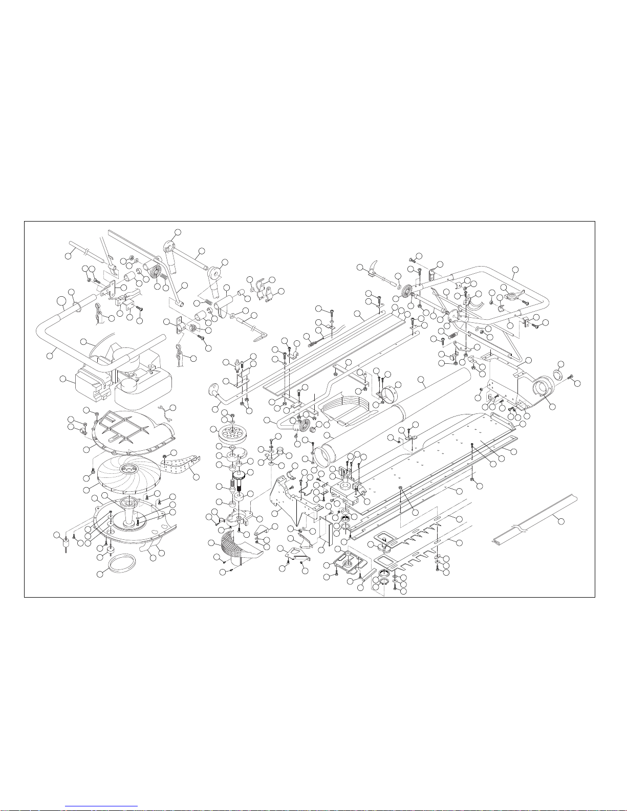
Chart Part No. Description Chart Part No. Description
1 R002-03500 Engine 61 A354-110003 Standing Plate
2 K162-050000 Flange Nut M5 62 008-254 Tension Bridge
3 K161-040000 Flange Nut M4 63 133-132 Upper Leaf Drawings (engine)
4 R037-000400 Nilon GripSN4A 64 K012-040060 Screw M4×
6
5 A190-100001 Fan CasingE 65 096-211 Lower Leaf Drawings (engine)
6 K049-060200 Upset Screw M6×2
0
66 K150-040000 Nut M4
7 R060-000100 Turbo Fan 67 K012-040060 Screw M4×
6
8 133-017 Casing (S) 68 008-273 Bag Hook
9 A035-007004 Engine Mount Rubbe
r
69 K150-040000 Nut M4
10 K164-050000 U Nut M
5
70 K012-040160 Screw M4×
6
11 021-186 Flat Washer 71 K012-040130 Screw M4×1
3
12 021-158 Casing Rubber Washer 72 K012-040080 Screw M4×
8
13 K012-040160 Screw M4×1
6
73 133-100 Crank Case (Upper)
14 K012-040140 Screw M4×1
4
74 096-116 Connecting Sleeve
15 021-155 Engine Mount Rubbe
r
75 009-259 Brushing Plate
16 K320-019000 V Belt (Center Line) M19 76 K031-040060 Screw for Sash M4×
6
17 133-130 First Duct 77 009-259 Brushing Plate
18 133-127 Second Duct 78 K031-040060 Screw for Sash M4×
6
19 K080-060186 Hole Bolt M6×18 79 R055-000100 Grease Nipple
20 K210-060000 Hole Bolt M6×18 80 K164-660000 Thin U Nut M6
21 096-155 Pulley (Engine) 81 K150-040000 Nut M4
22 K012-040080 Screw M4×
8
82 K352-060000 Bearing #6000 2RS
23 K012-040080 Screw M4×
8
83 R049-000100 Bearing RNU060405
24 A354-107003 Cover Pulley 1 84 K283-030000 C Stopper Ring STW30
25 K161-040000 Flange Nut M4 85 K031-050080 Screw for Sash M5×
6
26 062-224 Earth Lead Cable Wire 86 K354-006080 Bearing 608 2RS
27 A010-128003 Throttle Cable Wire 1210 87 096-118 Crank case (Lower
)
28 K152-10000L Hexagon Nut(Left) M10P1.5 88 K052-050160 Upset Screw M5×1
6
29 K225-100000 Plate Spring M10 89 K052-050160 Upset Screw M5×1
6
30 021-122 Pulle
y
90 096-119 Crankshaft
31 021-180 Pinionshaft Collar 91 R049-000100 Bearing RNU060405
32 096-110 Gear Case (Upper) 92 K283-030000 C Stopper Ring STW30
33 K350-006080 Bearing 608ZZ) 93 009-260 Felt
34 K352-060000 Bearing 6000RS) 94 092-133 Bridge
35 096-113 Output Gea
r
95 008-250 Blade Slide Washer
36 096-112 Pinion 96 008-246 Blade Slide Screw
37 K352-060000 Bearing 6000RS) 97 133-205 Bridge 18M
38 K350-006080 Bearing 608ZZ) 98 A151-124004 Blade Slide Washer
39 103-141 Gear Case (Lower
)
99 A040-007004 Blade Slide Screw
40 008-341 Metal Fitting 100 K164-060000 Thin U Nut M6
41 K016-040160 Small Screw M4×16 101 A254-365009 Lower Blade1210
42 K016-040140 Small Screw M4×14 102 A265-362009 Upper Blade1210
43 K016-040140 Small Screw M4×14 103 133-110 Slide Plate 1210
44 103-105 Cover & Fan Casing 104 K150-040000 Nut M4
45 K113-400100 Screw M4×1
0
105 K012-040080 Screw M4×
8
46 K113-400100 Screw M4×1
0
106 133-224 Blade Clip Plate1210
47 096-158 Engine Mount Rubber Sta
y
107 110-015 Bottom Frame1210
48 K204-050000 Flat Washer M5 108 008-256 Rubber Cap
49 K164-050000 U Nut M
5
109 K012-040080 Screw M4×
8
50 K040-060180 Hexagon Bolt M6×18 110 A035-005003 Grip Rubbe
r
51 K204-060000 Flat Washer M6 111 110-145 Duct Mounting Flange (Large)
52 103-129 Tension Arm 112 110-143 Side Frame (R)
53 021-196 Tension Metal 113 110-148 Leaf Drawing Plate (R)
54 A289-116002 Side Flame(L) 114 K012-040060 Screw M4×
8
55 A025-005004 Metal Fitting 115 K150-040000 Hexagon Nut M
4
56 K016-050210 Small Screw M5×12 116 110-144 Corner Block(R)
57 103-128 Belt Holder 117 K016-040100 Small Screw M4×10
58 K012-040100 Screw M4×1
0
118 K016-040160 Small Screw M4×16
59 K204-040000 Flat Washer M4 119 008-341 Metal Fitting
60 K150-040000 Nut M4 120 K150-040000 Nut M4
Parts Numbers
Nursery Supplies Australia Pty Ltd
ABN 74 071 051 208
Tel: +61 3 9737 7911 Fax: +61 3 7937 9899 Email: [email protected]
Page 13

Chart Part No. Description Chart Part No. Description
Parts Numbers
121 A025-010004 Metal Fitting 181 K161-040000 Flange Nut M4
122 K164-050000 U Nut M
5
182 A354-109004 TensionSta
y
123 110-104 Duct (Thin) Large 183 K150-050000 Nut M5
124 110-149 Band (Duct center) 184 A030-010003 Ajuster 0°
125 K016-040160 Small Screw M4×16 185 A354-103004 Lever Washer
126 K016-040300 Small Screw M4×30 186 A030-012003 Ajuster 70°
127 K150-040000 Nut M4 187 R030-001700 ThrottleLeve
r
128 103-104 Cover & Fan Casing 188 A354-102004 Short Handle lever 2
129 K016-040300 Small Screw M4×30 189 A354-100003 Short Handle
130 K199-040000 Square Nut M4 190 A035-006009 Grip Rubbe
r
131 A116-147004 Band (L) 191 133-207 U Handle
132 008-114 Coil Spring 192 K010-030180 Small Screw M3x1
8
133 K010-040320 Small Screw M4×32 193 A354-112004 RemitCover
134 110-015 Level Duct (thick) Extra Larg
e
194 A354-113004 U Handle Lead Cable
135 K164-050000 U Nut M5 195 A354-104004 U Handle Lever 1
136 K150-040000 Nut M4 196 K161-030000 Flange Nut M3
137 A354-116001 Frame Pipe1210(F) 197 K010-040050 Small Screw M4×
5
138 103-121 Frame Angle Iron (L) 198 A354-111003 Levershaft
139 096-154 Pipe Reinforcement 199 A354-117004 Lead Cable Stopper
140 K010-050320 Small Screw M5×32 200 008-300 Handle Fixing Nut
141 110-122 Frame Pipe (B) 201 008-304 Handle Bush
142 A035-007004 Engine Mount Rubbe
r
202 K207-080151 Flat Washer φ×18×1.5
143 103-130 Pipe Reinforcement R 203 K166-080000 U Nut 3types M
8
144 K010-050350 Small Screw M5×35 204 008-114 Coil Spring
145 A354-108004 Cover Pulley 2 205 A030-006003 Adjuster Slide R
146 K010-040300 Small Screw M4×30 206 A354-106003 U Handle Lever 3
147 K110-040800 Screw M4×
8
207 A003-030004 Screw Spring
148 084-135 Cable End Holder 208 K010-040050 Small Screw M4×
5
149 K204-040000 Flat Washer M4 209 A354-105004 U Handle Lever 2
150 A010-297003 Tension Cable Wire 210 A354-115003 Shoulder Band
151 K010-040300 Small Screw M4×30 211 A030-007003 Ajuster 45°
152 A025-009004 Metal Fitting 212 A030-005003 Adjuster Slide F
153 K010-050350 Small Screw M5×35 213 115-002 Handleshaft
154 092-129 Pipe R Washer 214 K207-080101 Flat Washer φ×28×1.0
155 K010-050300 Small Screw M5×30 215 008-114 Coil Spring
156 110-137 Transparent Plate 1210 216 A030-011003 Ajuster 70°
157 110-128 Transparent Plate Holder (F) 217 096-149 Handleshaft Collar
158 110-127 Transparent Plate Holder (B) 218 A030-004003 Slide S
159 096-132 Frame Angle Iron (Center) 219 A030-003003 Slide L
160 110-142 Band Collar 220 A031-001004 Binder Small Screw M5
161 K150-040000 Nut M4 221 008-320 Tip Cap
162 A015-014003 Handleshaft 222 008-223 Blade Cover
163 K207-080101 Flat Washer φ×28×1.0
164 K010-050350 Small Screw M5×35
165 K010-050350 Small Screw M5×35
166 A354-102004 Short Handle lever 2
167 K150-050000 Hexagon Nut M
5
168 062-185 Coil Spring
169 096-148 Handleshaft Collar
170 062-185 Coil Spring
171 A354-101003 Short Handle lever 1
172 A354-103004 Lever Washer
173 K161-050000 Flange Nut M5
174 K010-050400 Small Screw M5×40
175 A354-114004 Short Handle Lead Cable
176 K207-080151 Flat Washer φ×28×1.0
177 K166-080000 U Nut 3types M
8
178 008-287 Hook Coil Spring
179 K012-040100 Screw M4×1
0
180 A116-168004 Cable Holder
Nursery Supplies Australia Pty Ltd
ABN 74 071 051 208
Tel: +61 3 9737 7911 Fax: +61 3 7937 9899 Email: [email protected]
 Loading...