

Page 1

NUREVA™ SPAN™ SYSTEM
INSTALLATION GUIDE
February 2017
Page 2
Important
SAFETY WARNINGS
Prior to installing this product, ensure you fully read and understand the installation instructions.
Failure to do so could result in personal injury or property damage. You are responsible for
ensuring all components are properly assembled and installed using the instructions provided.
Keep this information sheet and related product manuals for future reference.
SAFETY WARNINGS
The manufacturer shall not be legally responsible for any property damage or personal injury caused by incorrect installation
of the equipment or operation outside of the user’s manual. The manufacturer shall not be liable for damage to property or
personal injuries arising out of factors beyond the manufacturer’s control.
WARNING: This projector is a Class 2 laser device. Do not stare into the projector beam. The bright light
may result in permanent eye damage.
WARNING: The touch module is certified as a Class 1 laser device. Do not open or disassemble the touch
module. Any operation or adjustment not specifically instructed by the user’s guide creates the risk of
hazardous laser radiation exposure.
WARNING: Never operate this equipment if it is damaged. Do not modify the parts or accessories.
Opening the projector’s case exposes you to risk of electrical shock. Do not use with parts or accessories
not recommended by the manufacturer. Contact your reseller with questions regarding replacement
parts.
WARNING: Ensure that any cables used with the equipment are properly bundled, routed, covered or
constrained if they cross the floor or pose a tripping hazard.
WARNING: Failure to provide adequate structural strength for the wall mount can result in serious
personal injury or damage to property. The anchors and wall to which this equipment is attached can
support four times the combined weight of all equipment. Ensure the wall structure is reinforced as
required before installing the equipment.
WARNING: Exceeding the wall mount’s weight capacity can result in serious personal injury or damage to
equipment. The installer is responsible for ensuring the combined weight of all components attached to
the wall mount does not exceed 33 lb. (15 kg).
WARNING: Adding additional weight to the boom by leaning, hanging or storing items on it can result in
serious personal injury or damage to property.
IMPORTANT: Do not use chemical or abrasive cleaners on the equipment.
IMPORTANT: Avoid touching the optical components to prevent scratches.
IMPORTANT: Do not expose the equipment to moisture or damp environments. This equipment is not intended for
outdoor use.
IMPORTANT: This product can expose you to chemicals including DINP, a chemical known to the State of California to
cause birth defects or other reproductive harm. For more information, go to www.P65Warnings.ca.gov/products.
2
February 2017
Page 3

Important
SAFETY WARNINGS
NOTICE: This projector is a Class 2 laser device that conforms to IEC 60825-1: 2007 and CFR 1040.10 and 1040.11.
Except for deviations to Laser Notice No.50 dated June 24 2007.
FCC NOTICE
This device has been tested and found to comply with the limits for a Class B digital device pursuant to Part 15 of the
FCC rules. These limits are designed to provide reasonable protection against harmful interference in a residential
installation. This device generates, uses and can radiate radio frequency energy and, if not installed and used in
accordance with the instructions, may cause harmful interference to radio communications. However, there is no
guarantee that interference will not occur in a particular installation. If this device does cause harmful interference to
radio or television reception, which can be determined by turning the device off and on, the user is encouraged to try to
correct the interference by one or more of the following measures:
• Reorient or relocate the receiving antenna
• Increase the separation between the device and receiver
• Connect the device into an outlet on a circuit different from that to which the receiver is connected
• Consult the dealer or an experienced radio/television technician for help
SHIELDED CABLES: All connections to other computing devices must be made using shielded cables to maintain
compliance with FCC regulations.
CAUTION: Changes or modifications not expressly approved by the manufacturer could void the user’s authority, which
is granted by the Federal Communications Commission, to operate this projector.
OPERATION CONDITIONS: This device complies with Part 15 of the FCC Rules. Operation is subject to the following two
conditions:
1. This device may not cause harmful interference and
2. This device must accept any interference received, including interference that may cause undesired operation
INDUSTRY CANADA STATEMENT
This Class A/B digital apparatus meets all requirements of the Canadian Interference Causing Equipment Regulations.
Operation is subject to the following two conditions:
1. This device may not cause harmful interference, and
2. This device must accept any interference received, including interference that may cause undesired operation
3February 2017
Page 4

Table of contents
BEFORE YOU BEGIN
What’s in the box
You must supply
INSTALLATION — DO THE INSTALLATION IN THIS ORDER
1. Determine the installation location
2. Install the hardware brackets
3. Install the hardware
4. Connect the hardware
5. Initial adjustment of the projected image(s)
6. Install the surfaces
5
6
7
8
11
15
16
18
7. Download Span wall software and touch driver
8. Set up touch
9. Final adjustment of the projected image(s)
10. Launch Span software
11. Troubleshooting
19
20
24
27
28
4
February 2017
Page 5
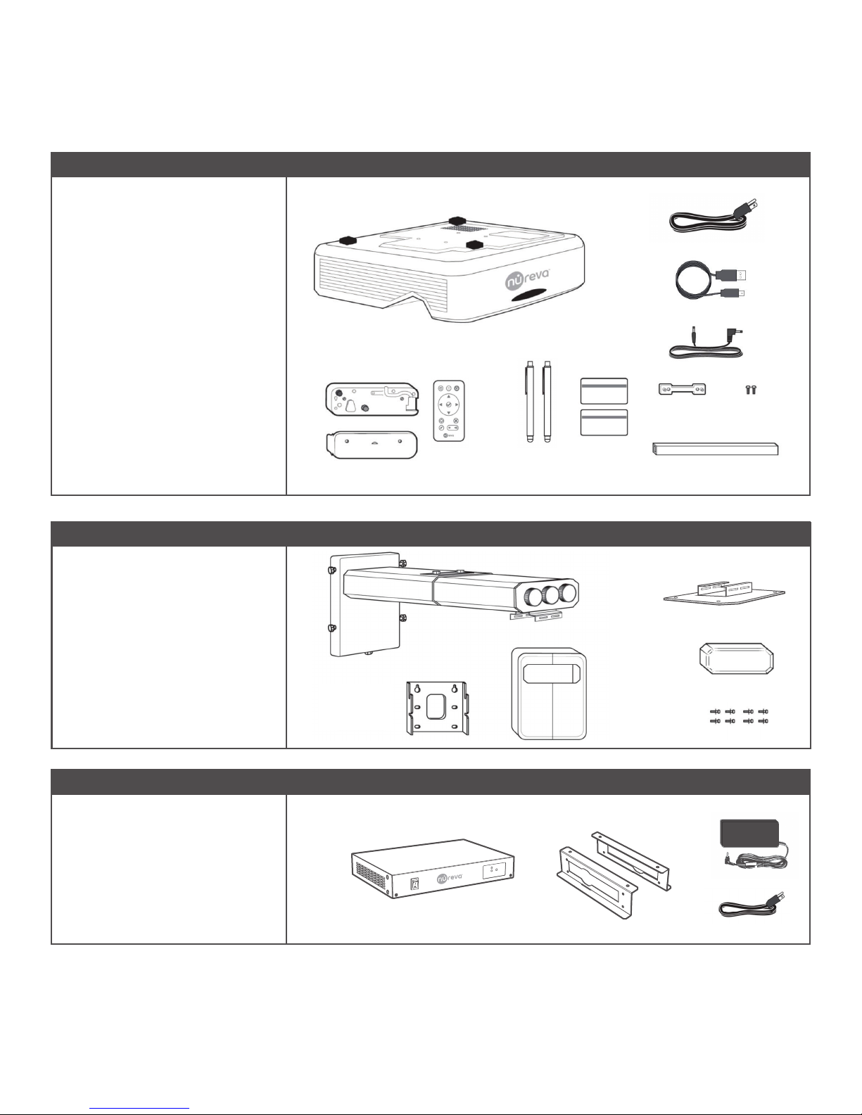
What’s in the box
BOX 1: NPSi-1 or NSPi1080-1
A Interactive projector
B Touch module
C Projector remote control
D Stylus x 2
E Power cable
F USB cable 16.4' (5 m)
G Touch module power cord
H Alignment card
I Touch module bracket
J Screws to attach touch module to
bracket
K Wire cover
L Wall mount boom
M Wall mount plate
E
F
A
B
C
D
H
G
I
J
K
BOX 2: NWM-1
N
N Projector plate
O Wall mount cover (L/R)
P Adjustment cover
Q Screws to attach plate to projector
(x4) and screws to attach projector
to mount (x4).
R Alignment module
S Wall bracket
T Power adapter
U Power cable
L
P
M
O
Q
BOX 3: NAM
S
R
T
U
February 2017
5
Page 6
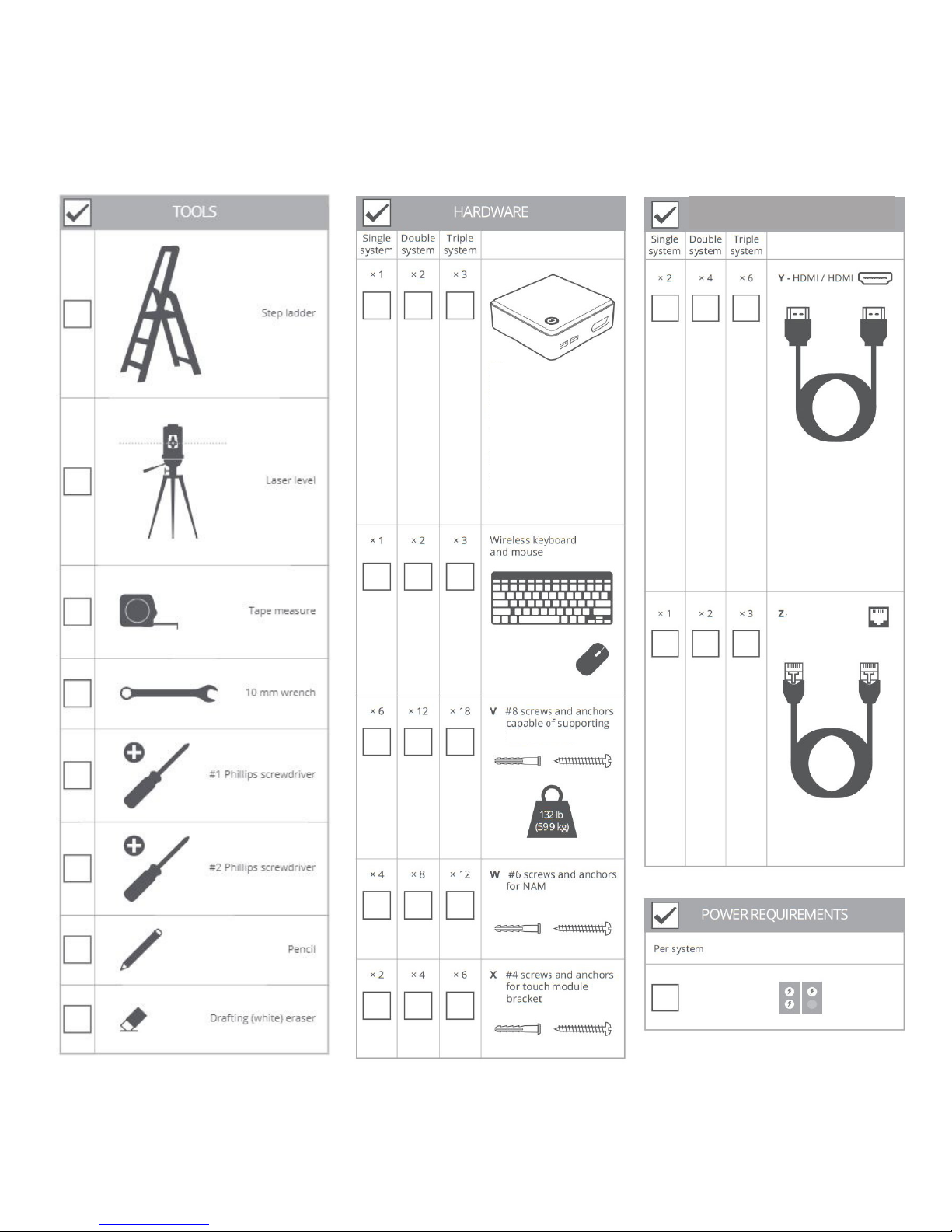
You must supply
To install the system successfully you need to provide the following items. Go through these
checklists and ensure everything is on hand before you begin to install the system.
CABLES AND CONNECTORS
PC
Must meet the following
specications:
• Windows® 8.1 or higher
• Intel® i5 or equivalent
• HDMI video out port or
adapter
• Supports 1920 x 720
or 1920 x 1080 display
resolution
• 4GB+ RAM
• 2GB+ free storage
132 lb. (59.9 kg)
RJ45/RJ45
6
February 2017
Page 7
1.
Determine the installation location
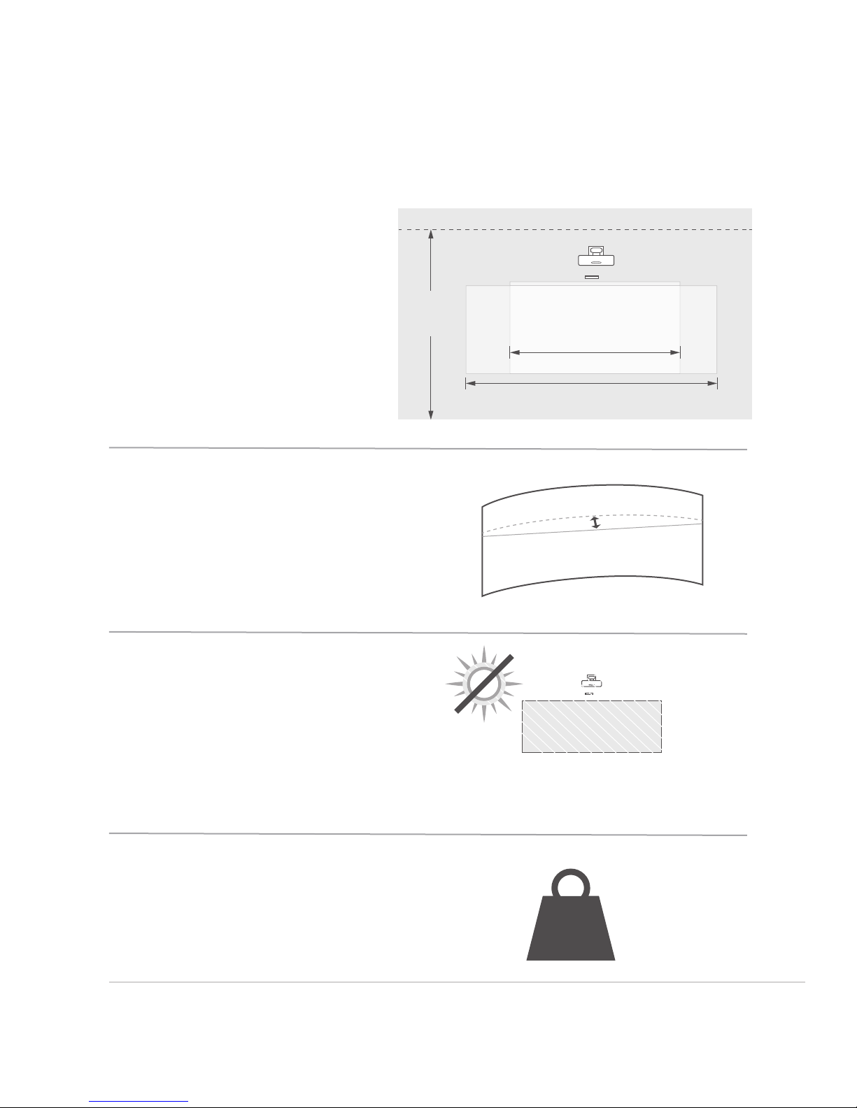
Ensure the area you select to install your system meets the following
requirements and recommendations.
SPACE REQUIREMENTS
Locate the installation drawing
for your system’s conguration
in the appendix of this
guide for the detailed space
requirements.
102”
(260 cm)
MIN.
WM307i -
84” (213.4 cm)
Wall atness requirement
Install away from direct
sunlight.
WM210i -
MAX. 1/4” (6mm)
122" (310 cm)
124” (315 cm)
Wall load requirements per
system
February 2017
132 lb.
(60 kg)
7
Page 8
Install the hardware brackets2.
Install the wall mount plate(s) 2.1
2.1.1
2.1.2
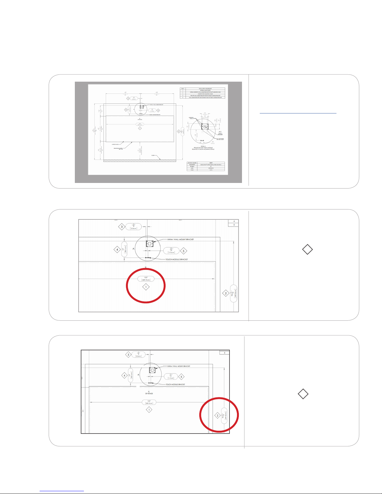
Download the installation
drawing for your system's
conguration from
nureva-span.uservoice.com
Measure and mark the system
centerline.
Refer to installation
measurement 1 on your
installation drawing.
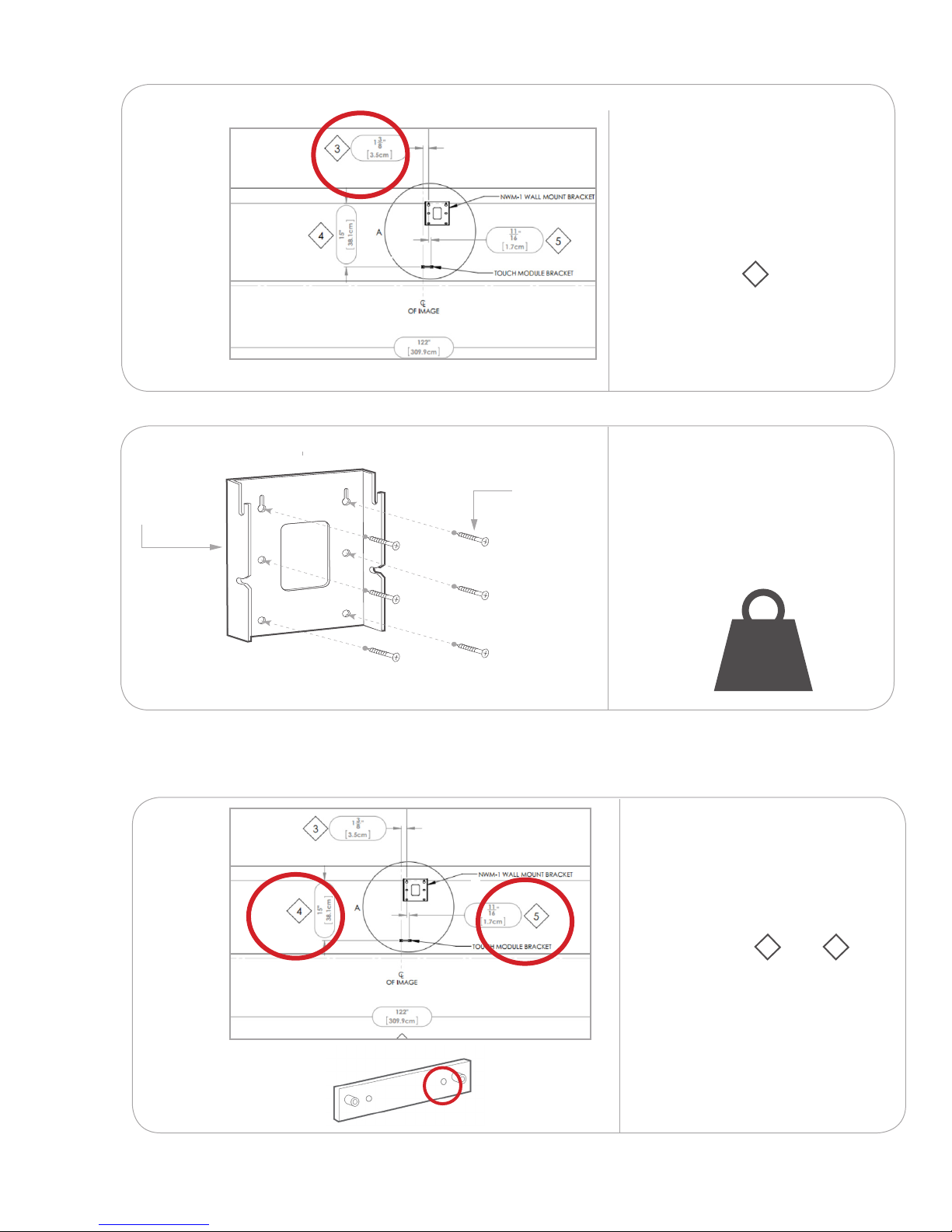
2.1.3
8
From the centerline, measure
from the oor to the top of the
wall mount plate holes. Mark
that spot.
xx
February 2017
Refer to installation
measurement 2 on your
installation drawing.
Page 9
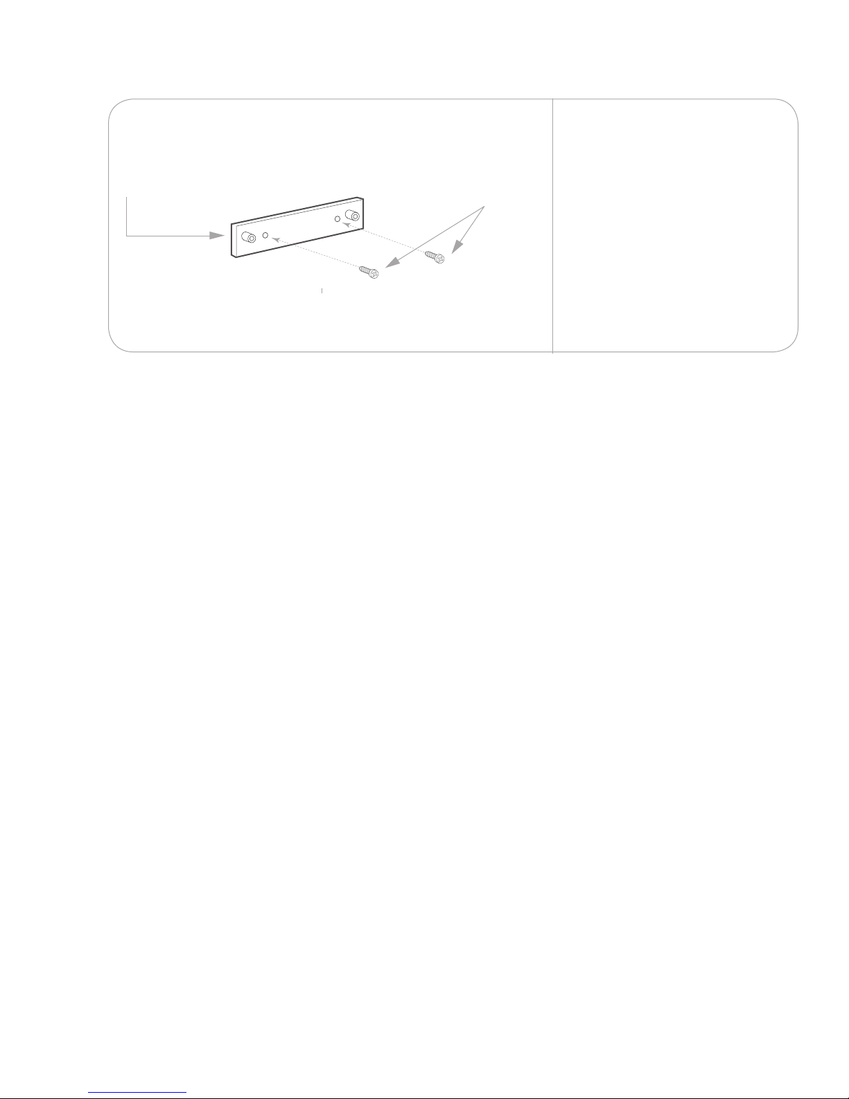
2.1.4
Measure from the spot you
xx
marked on the centerline to
the top left wall mount plate
hole. Mark the remaining wall
plate holes.
2.1.5
M
xx
Refer to installation
measurement 3 on your
installation drawing.
Ensure the wall mount plate is
V ×6
level.
Attach the wall mount plate(s)
.
33 lb
(15 kg)
to the wall using screws and
anchors capable of supporting
132 lb. (60 kg).
132 lb.
(60 kg)
2.2
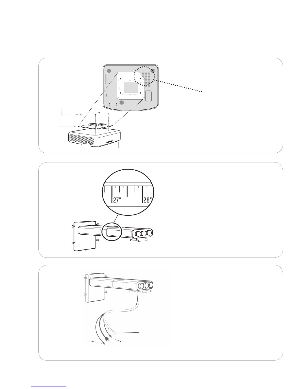
Install the touch module bracket(s)
2.2.1
xx
February 2017
Measure down and over from
the top-left hole of the wall
mount plate to the inside-right
hole on the touch module
bracket.
Refer to installation
measurement 4 and 5
on your installation drawing.
NOTE: If you are installing a
Da-Lite screen, the touch
module brackets are installed
as part of the screen. Follow
the instructions provided with
the screen to install the touch
module brackets.
9
Page 10
2.2.2
I
x
X 2
Ensure the bracket is level.
Attach the touch module
bracket to the wall using the
#4 screws and anchors. Repeat
with any remaining brackets.
10
February 2017
Page 11
3.
Install the hardware
Install the wall mount boom and projector
3.1
3.1.1
3.1.2
N
Q
x 4
Attach the projector plate(s)
with four of the screws
provided.
Position the plate so the
angled edge is closest to the
projector vent.
A
Adjust the boom length to
• 27.5” for NPSi-1projector
• 17.5” for NPSi1080-1
projector
and tighten the top bolts.
Repeat with the remaining
booms.
3.1.3
Touch module
power
G
HDMI
Y
Mini
USB
F
note: If the mount or projection
surface is extended or recessed,
add or subtract the dierence
from this measurement.
Feed the projector power
cord, mini USB cable, HDMI
cables and touch module
cord through the wall mount
boom. Ensure the correct
connector ends are being
fed through. Repeat with the
remaining booms.
Projector
power
E
February 2017
11
Page 12
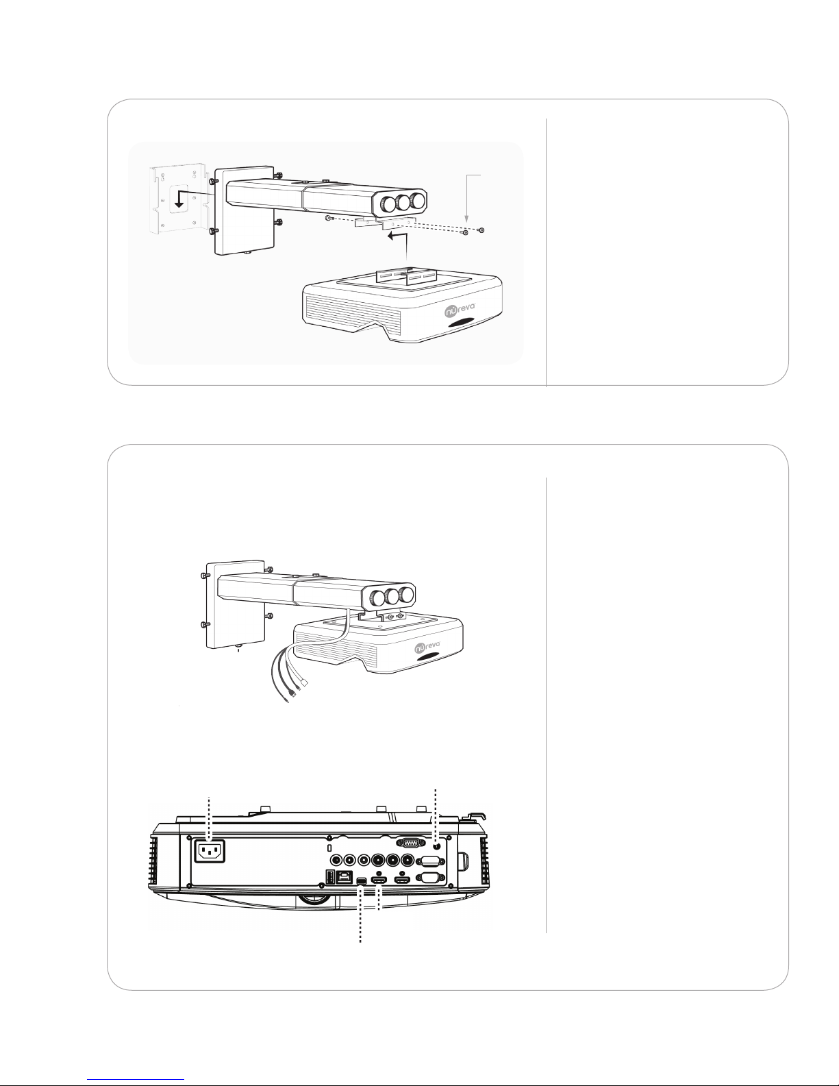
3.1.4
PROJECTOR
POWER CORD
HDMI
MINI USB
TOUCH MODULE
POWER CORD
PROJECTOR
POWER CORD
PROJECTOR
POWER CORD
PROJECTOR
POWER CORD
HDMIHDMIHDMI
MINI USBMINI USBMINI USB
TOUCH MODULE
POWER CORD
TOUCH MODULE
POWER CORD
TOUCH MODULE
POWER CORD
3.1.5
p X4p X4p X4p X4
Q
Attach the wall mount boom
to the wall mount plate.
X 4
Attach the projector to the
boom with four of the screws
provided.
Repeat with any remaining
booms and projectors.
UP/DOWNUP/DOWNUP/DOWNUP/DOWN
Projector power
Attach the cables from the
mount to the back of the
projector.
Touch module power
HDMI
12
Mini USB
February 2017
Page 13
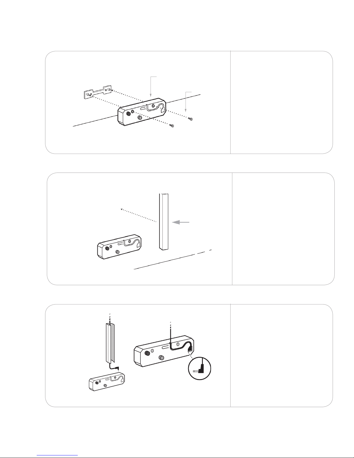
3.2
kkkk
Install the touch module
3.2.1
3.2.2
B
K
Remove the touch module
cover.
Attach the unit to the
J
X 2
bracket using the two screws
provided. Ensure the unit is
seated securely against the
wall.
NOTE: If you are installing a
Da-Lite screen, follow the
instructions provided with
the screen to install the touch
module(s).
Test-t the wire cover to
conceal the touch module
power cord. Trim the cover if
necessary.
Remove the adhesive liner to
attach the cover to the wall.
3.2.3
Lay the touch module power
cord in the wire cover and
plug it into the touch module.
Leave the touch module cover
o.
Repeat with any remaining
touch modules.
February 2017
13
Page 14
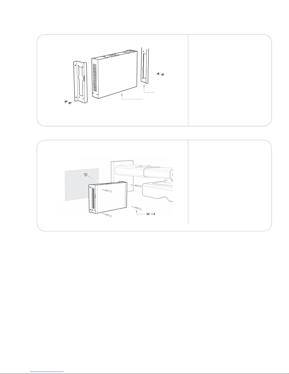
Install the NAM image alignment module3.3
3.3.1
3.3.2
If you are using the mounting
brackets, attach them to
the NAM using the screws
provided on the sides of the
NAM.
S
R
If you are mounting the
NAM(s), use the #6 screws
and appropriate anchors a
minimum of 5” (12.7 cm) away
from the projector mounting
plate.
14
February 2017
Page 15
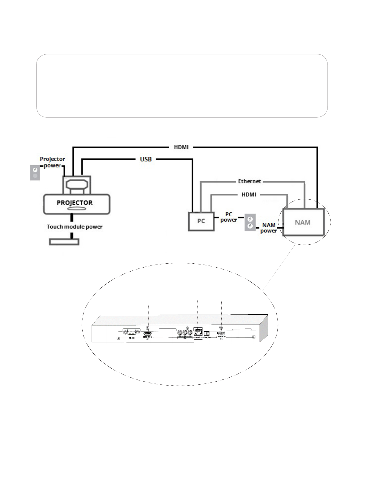
Connect the hardware
4.
Ensure your IPV4 Ethernet port is enabled correctly.
If you are hardwiring your PC to your network, you may need a USB-Ethernet
adapter to connect the second Ethernet cable to your PC.
HDMI out
(to projector)
Ethernet
(to PC)
February 2017
HDMI in
(to PC)
15
Page 16
5.
UP/DOWN
LEFT/RIGHT
IMAGE SIZE
IMAGE
ADJUSTMENT
UP/DOWNUP/DOWNUP/DOWN
LEFT/RIGHTLEFT/RIGHTLEFT/RIGHT
IMAGE SIZEIMAGE SIZEIMAGE SIZE
IMAGE
ADJUSTMENT
IMAGE
ADJUSTMENT
IMAGE
ADJUSTMENT
Initial adjustment of the projected image(s)
5.1.1
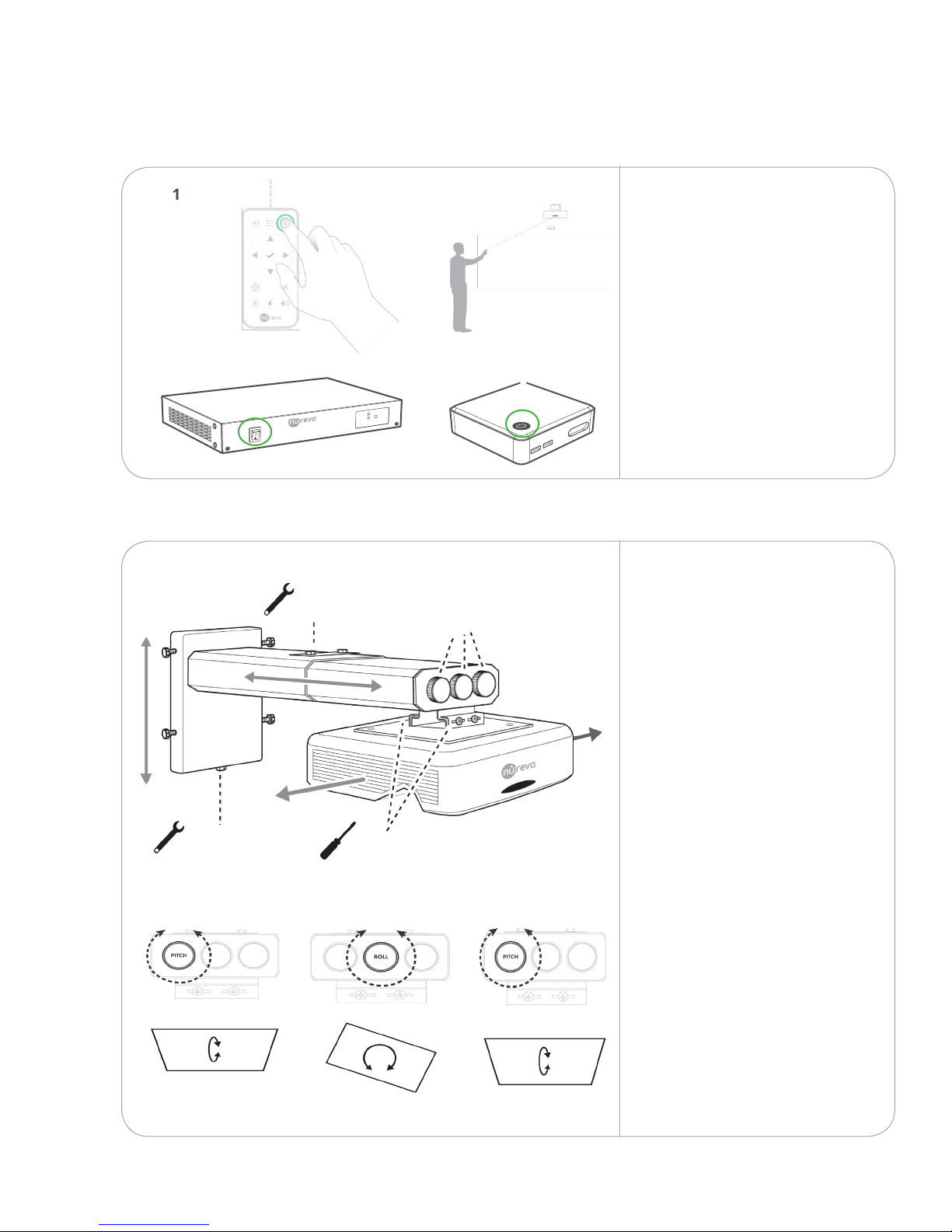
Power on the NAM, projector
and PC.
5.1.2 Use the adjustment options
on the mount to straighten
and square o the projected
image.
Do not worry about
precision at this stage. You
will be using software to
adjust the images later on in
the process.
16
February 2017
Page 17
5.1.3
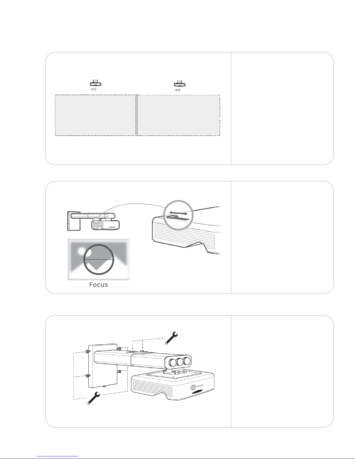
For double and triple
congurations, ensure each
projected image has at least
1" (2.5 cm) of overlap.
For corner, edge and
surround congurations,
reference your installation
drawing for the gap required
between each projected
image.
5.1.4
5.1.5
Use the slider on the side
of the projector to bring the
image into focus. Repeat with
any remaining projectors.
Tighten the bolts and
screws on the mount(s) and
projector(s) once you have
completed adjusting the
image(s).
February 2017
17
Page 18
6. Install the surface(s)
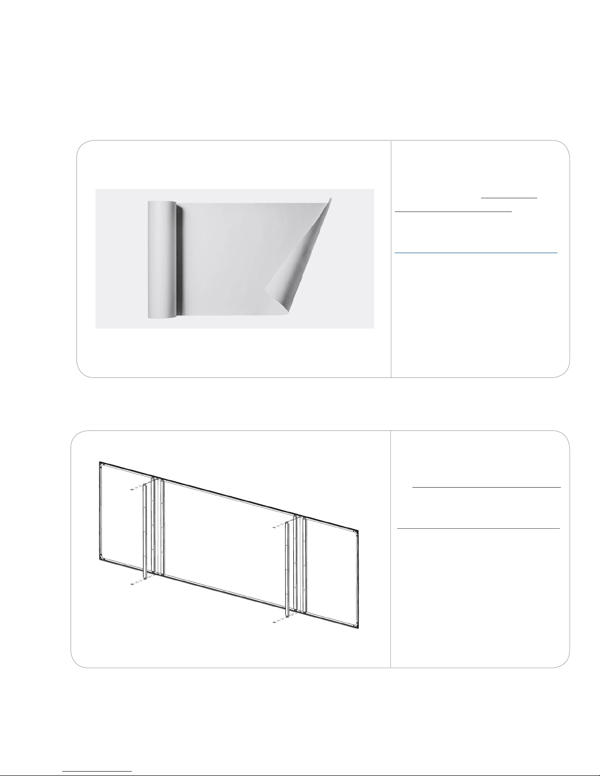
Follow the installation guide for your selected surface.
To install the WhisperTek™
surface, follow the WhisperTek
surface installation guide.
Go to
https://nureva-span.uservoice.com/
Search
WhisperTek
18
To install the Da-Lite screen, follow
the Da-Lite screen installation guide.
Go to:
https://nureva-span.uservoice.com/
Search:
Da-Lite
February 2017
Page 19
7.
Download Span wall software and touch driver
7.1.1
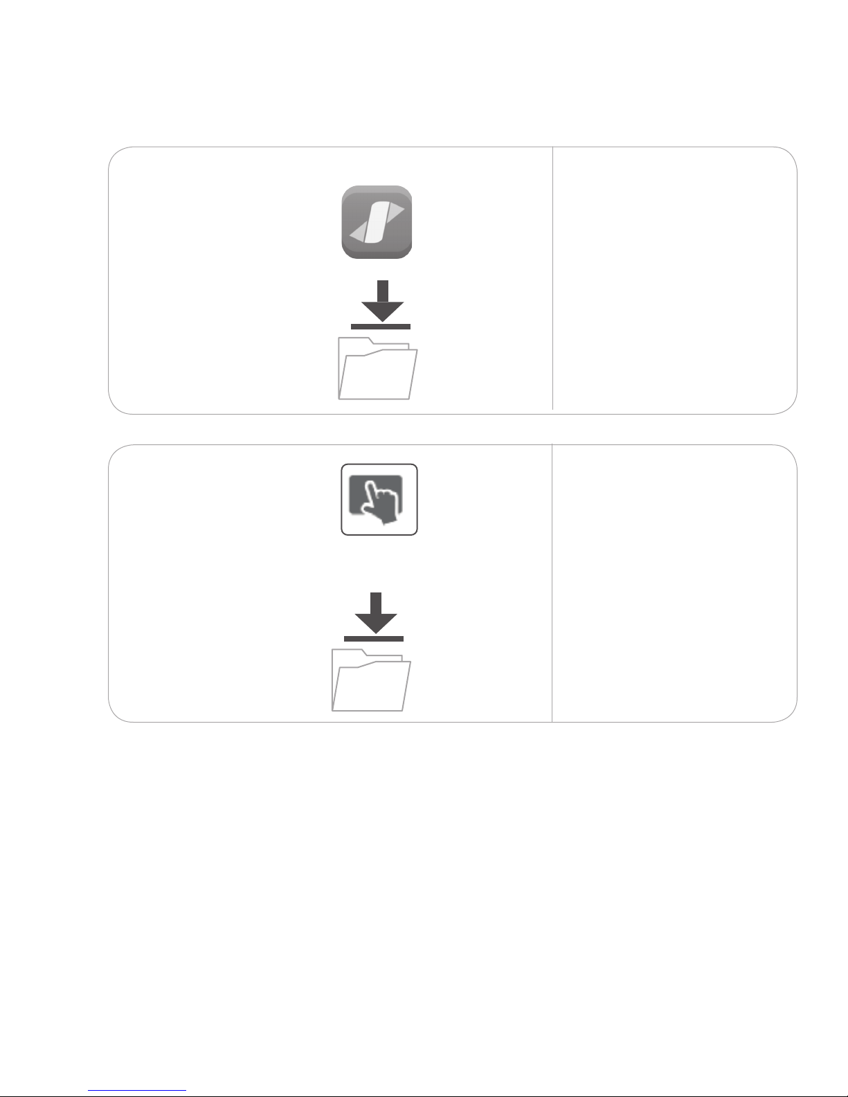
Use the wireless keyboard
and mouse to navigate to the
Internet.
Download and install Span
wall software from the
Download section at
nureva-span.uservoice.com.
7.1.2
T
ouch
driver
Download and install the
touch driver from the
Download section at
nureva-span.uservoice.com.
The touch driver must be
installed in order to set up the
interactive image in step 6.
February 2017
19
Page 20
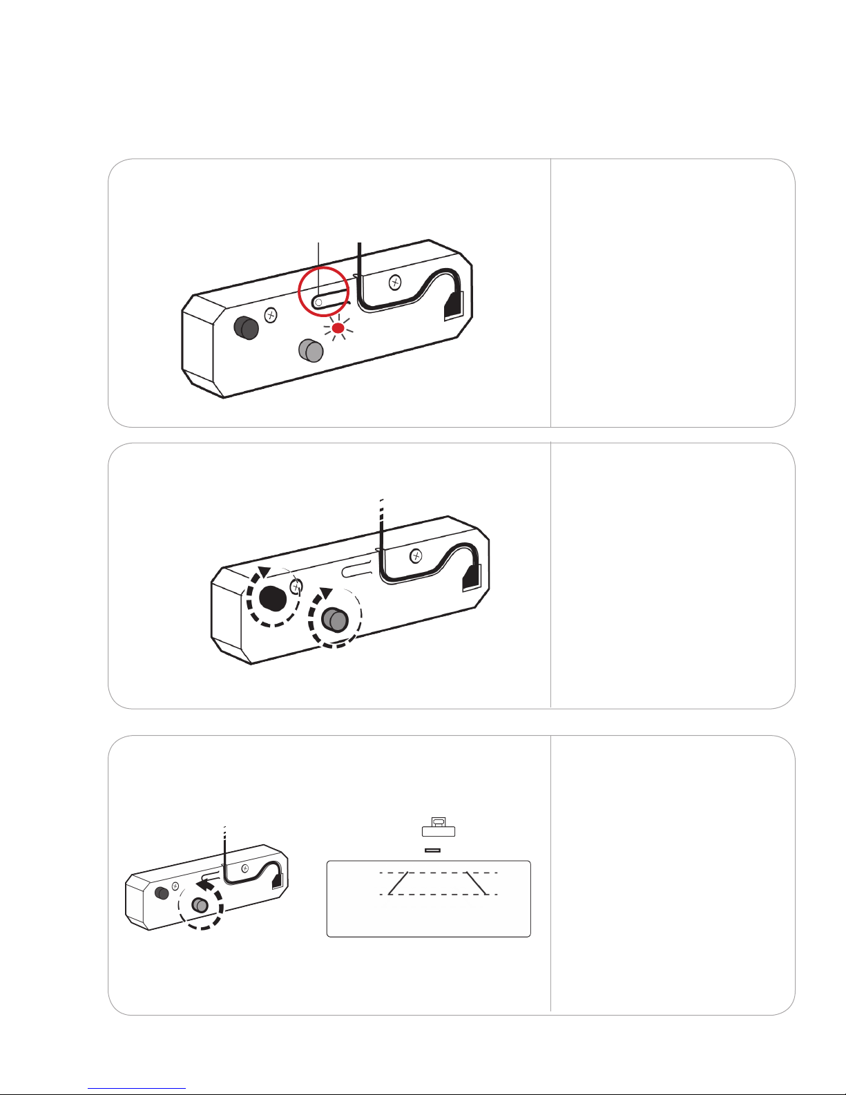
ADJUSTMENT ON/OFFADJUSTMENT ON/OFF
8.
Set up touch
Set up the touch module laser curtain8.1
8.1.1
8.1.2
Adjustment mode on/o
Press the adjustment button
to turn the touch module to
adjustment mode. This will
emit two visible laser beams
from the bottom of the unit.
The LED light will blink red
and blue when the touch
module is in adjustment
mode.
Rotate both the black and
grey knobs clockwise until
they cannot be turned any
further.
8.1.3
20
Rotate the grey knob
counterclockwise until
both lasers beams that
are being emitted from
the bottom of the touch
module align symmetrically.
February 2017
Page 21
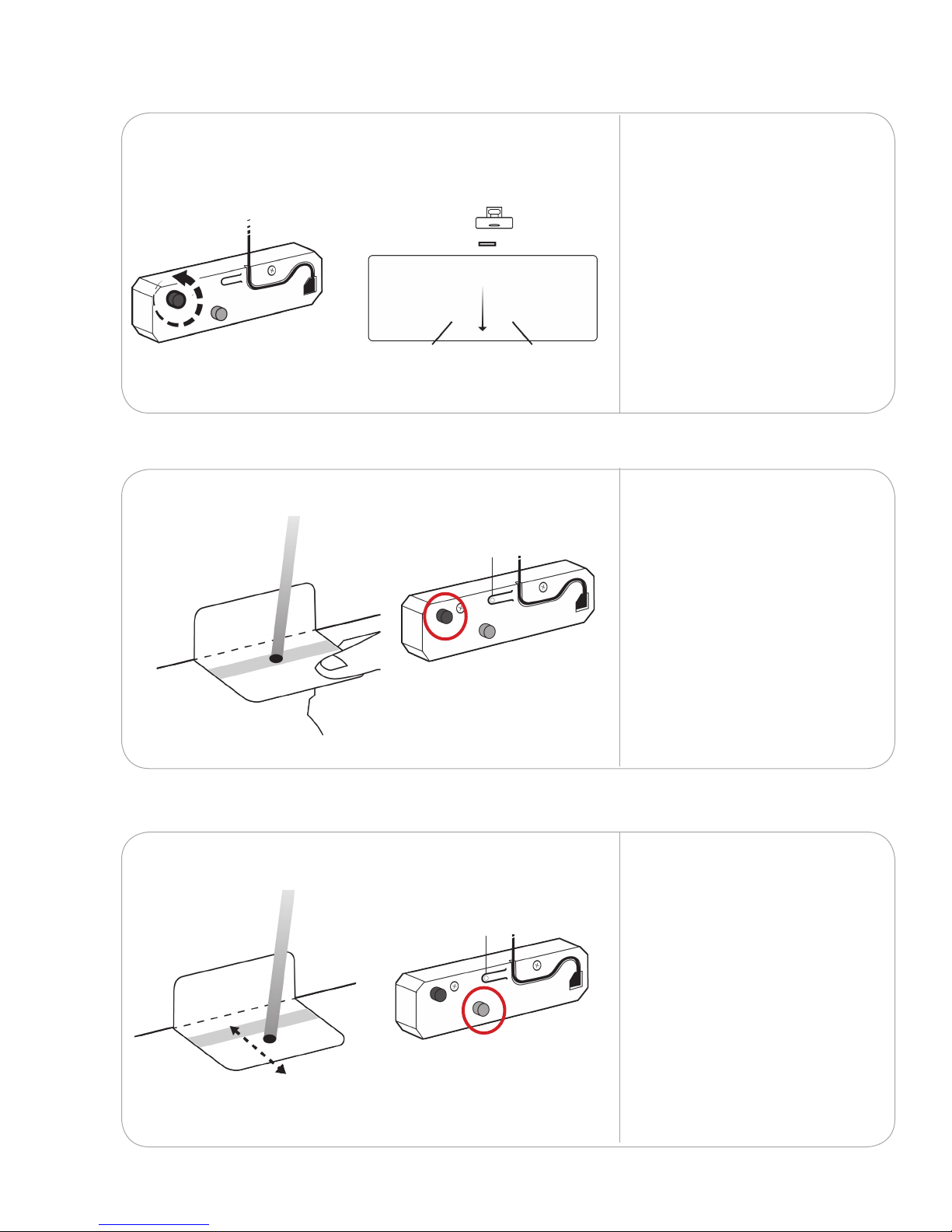
8.1.4
ADJUSTMENT ON/OFFADJUSTMENT ON/OFF
ADJUSTMENT ON/OFFADJUSTMENT ON/OFF
Rotate the black knob
counterclockwise to move
the laser beams downward
until they appear on the
oor or surface below
the projected image.
8.1.5
8.1.6
Fold the laser alignment
cards along the dotted line.
Hold the alignment cards
against the wall to check
if the laser falls within the
grey zone. If the dots are
blurred or scattered, adjust
the black knob until they
are properly dened.
Repeat with the other laser.
If your wall atness varies
causing the laser to fall
outside of the grey zone,
use the grey knob to
adjust the distance of
the laser from the wall.
February 2017
Repeat with the other laser.
21
Page 22
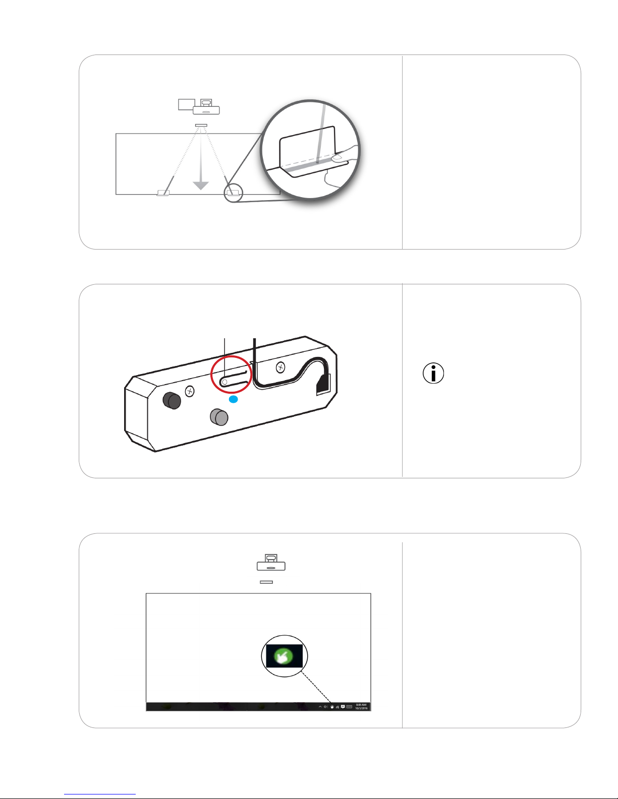
8.1.7
ADJUSTMENT ON/OFFADJUSTMENT ON/OFF
Slide the card diagonally
toward the touch module
to check if the dot stays
within the grey zone all the
way to the top. Repeat this
process on the other beam.
Ensure both beams are an
equal distance from the wall.
8.1.8
Adjustment mode on/o
Touch driver settings8.2
8.2.1
Press the adjustment button
to switch o adjustment
mode. The LED will turn a
solid blue.
IMPORTANT: Touch does not
function when the module
is in adjustment mode.
Launch the touch driver
from the icon located on
the desktop task bar.
22
February 2017
Page 23
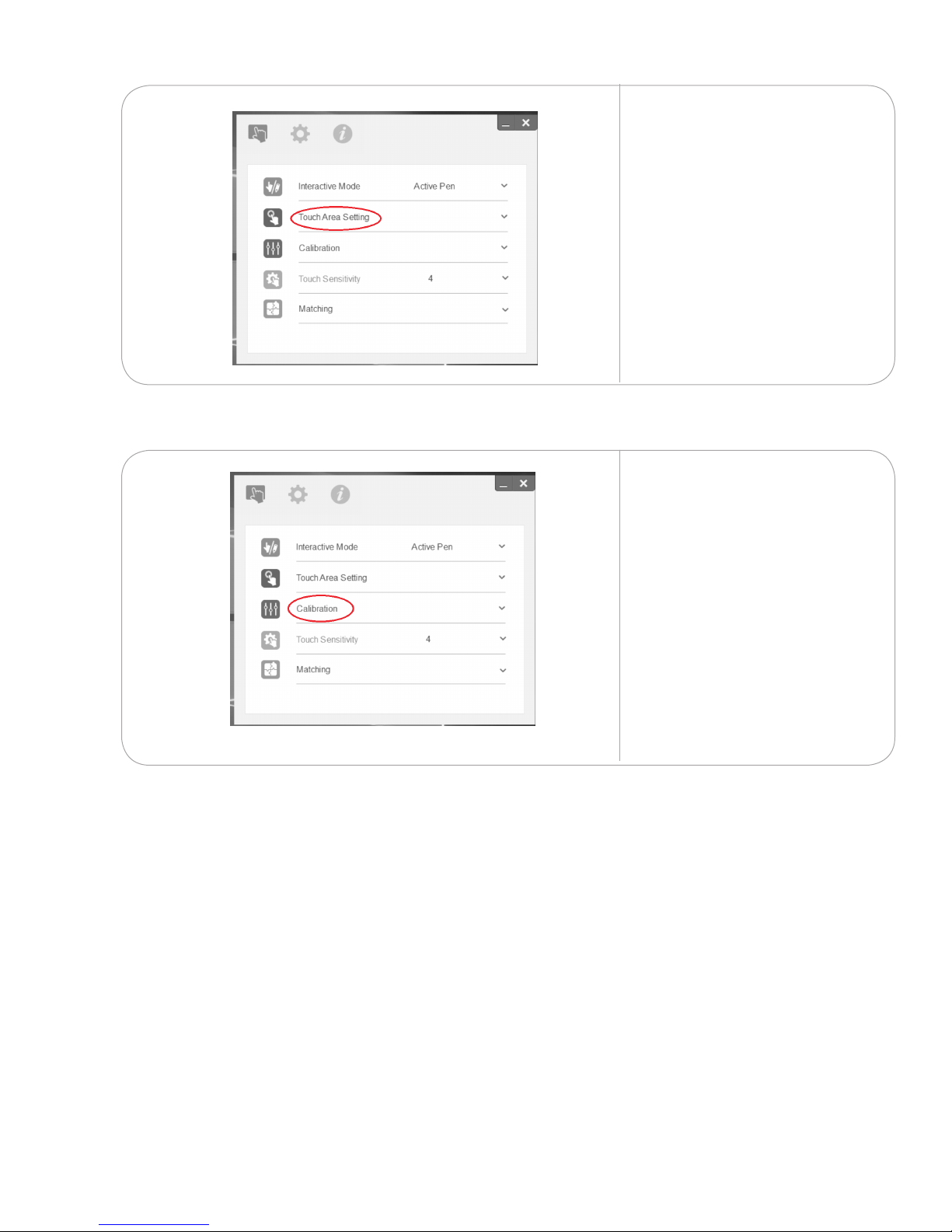
8.2.2
Select Touch Area
Setting and choose Auto
from the drop-down
menu. The screen will
ash a series of dots.
Click OK.
8.2.3
Select Calibration from
the menu and choose
Auto from the drop-down
menu. The screen will ash
a series of dots. Click OK.
Repeat the touch area
setting steps on any
remaining PCs.
Touch should now
be enabled on the
projected images.
February 2017
23
Page 24
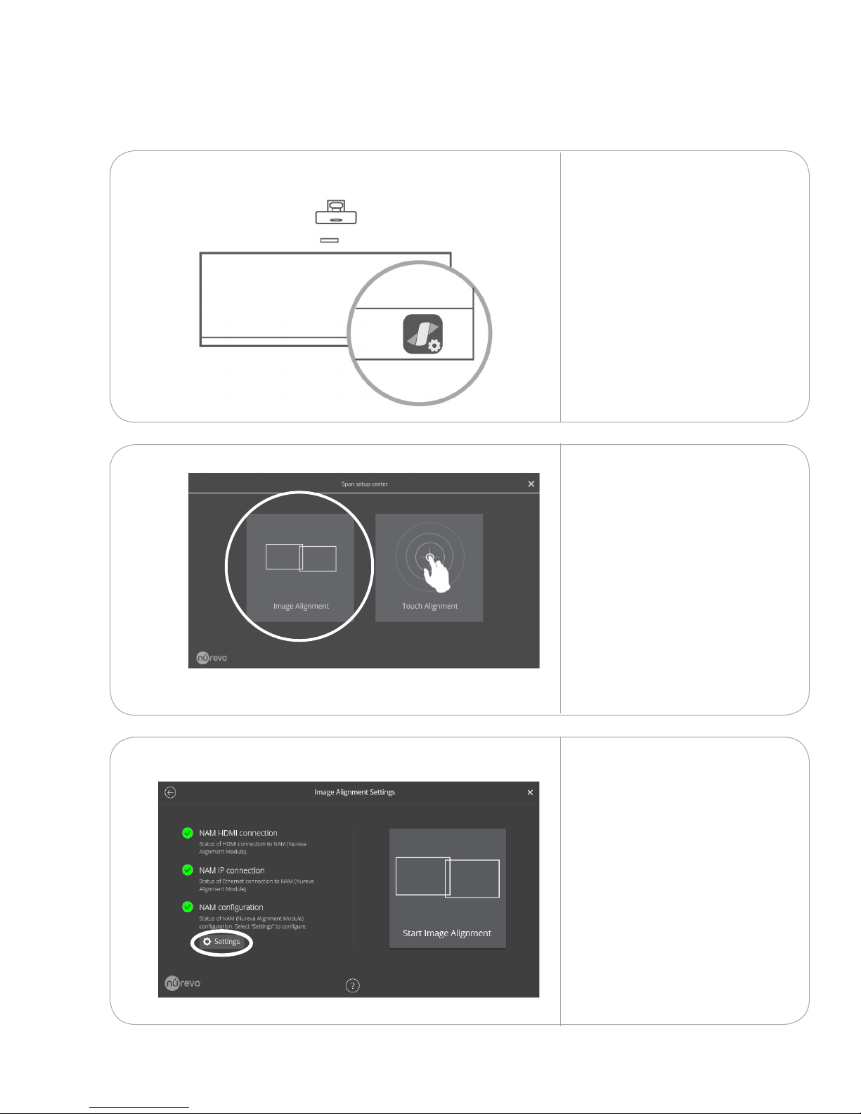
9.
Final adjustment of the projected image(s)
9.1
Align the image(s)
9.1.1
9.1.2
Launch Span center from
the icon located on the
desktop task bar on each
of the projected images.
Select Image Alignment.
The Span center allows
you to use touch to shrink
the images until they are
square and aligned.
9.1.3
24
Tap on Settings
February 2017
Page 25
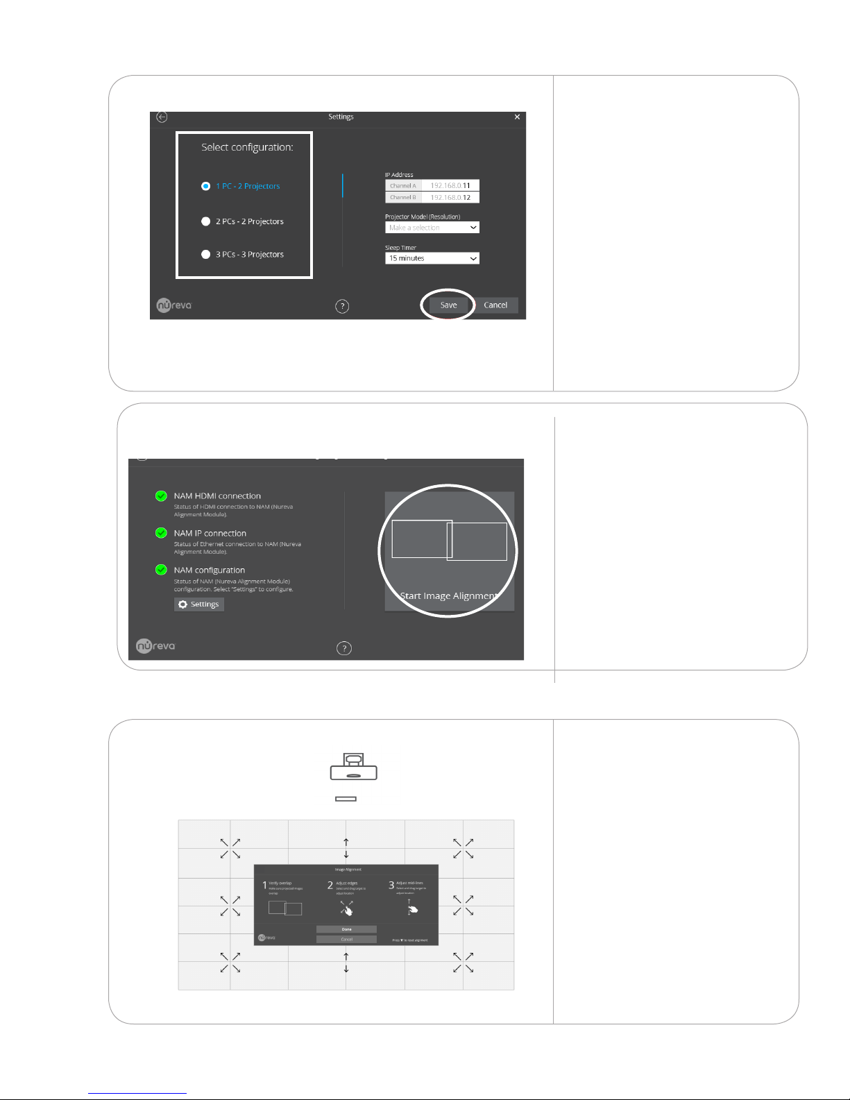
9.1.4
1. Select your system’s PC/
projector conguration.
NOTE: If you have 1 projector and
1 PC, select 2PCs - 2 Projectors
2. Ensure the IP addresses are
192.168.0.11 and 192.168.0.12
3. Ensure the correct Projector
Model (Resolution) is set.
NPSi-1 projectors
1920 x 720
NPSi1080-1 projectors
1920 x 1080
4. Ensure Sleep Timer is
set to 15 minutes
5. Tap Save
9.1.5
9.1.6
Next, tap Start Image
Alignment.
Repeat these steps on
any remaining screens.
Drag and adjust the image
into precise alignment.
If you have a double or triple
conguration, start with the
largest image and adjust it
to t the smaller images.
February 2017
If you have a corner or
surround conguration,
reference your installation
drawing for the minimum
clearance needed
between the images.
25
Page 26
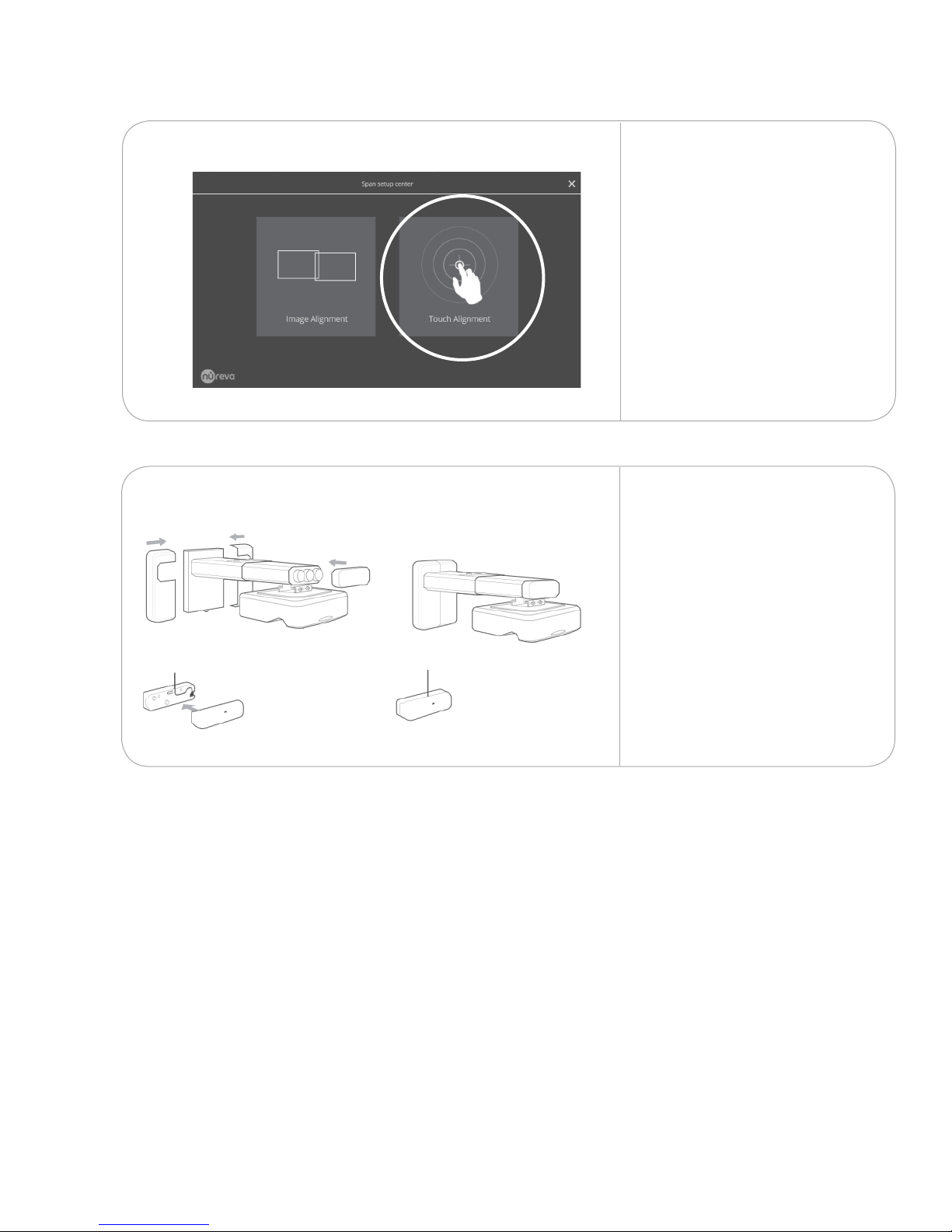
9.2
9.2.2
Calibrate touch
9.2.1
Click Done once you
have completed the
image alignment.
Select Touch Calibration.
The screen will ash a
series of dots. Repeat on
any remaining displays.
Attach the plastic covers
to the wall mount plate,
wall mount boom and
touch module.
26
February 2017
Page 27
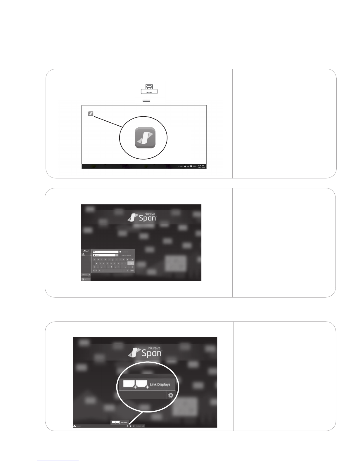
Launch Span software10.
10.1
Launch the wall software
10.1.1 On each projected image,
launch Span wall software
from the icon on the desktop.
10.1.2
For congurations with
multiple displays, log in
to the software on one
of the displays. This will
automatically log you in on
the other projected images.
10.2
Link displays (for congurations with PCs)
10.2.1
February 2017
A Link displays dialog will
appear after logging in. If it
does not, tap the gear icon to
bring it up.
27
Page 28
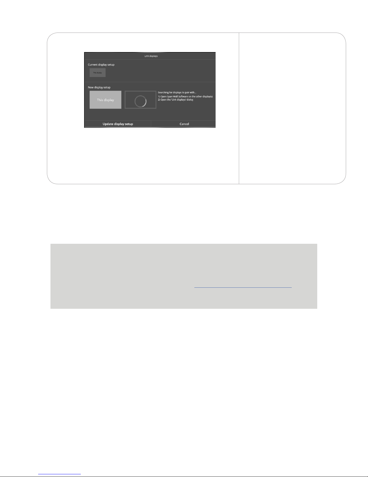
10.2.2 If you are on the left display,
ensure the left display box
says This display and vice
versa if you are on the right
display.
Repeat this step with the
remaining displays. Once you
have linked all of the displays
tap Update display setup.
NOTE: Linking displays only
needs to be done on the
initial log in. The system
saves the display settings
and applies them to all
subsequent log ins.
Troubleshoong
For troubleshoong, please see our Customer support portal.
hps://nureva-span.uservoice.com
28
February 2017
 Loading...