


SERVICE MANUAL
SERVICE MANUAL
Edition Date Modifications
01 12/2015 First Edition
02 09/2016 Wiring diagram tank version updated
II
Ed. 02 of 09/2016

SERVICE MANUAL
MACHINE DESCRIPTION
FIRST INSTALLATION AND
PRELIMINARY OPERATIONS
REMOVAL OF THE EXTERNAL
SURFACE
INFUSION UNIT
HEATER
HYDRAULIC CIRCUIT
ELECTRIC COMPONENTS
TROUBLESHOOTING
1
2
3
4
5
6
7
8
DIAGRAMS
MAINTENANCE CHECKING
SPARE PART CATALOGUE
9
10
11
Ed. 02 of 09/2016
I

INDEX
SERVICE MANUAL
1. MACHINE DESCRIPTION ........1.1
1.1 DESCRIPTION ...................1.2
1.2 KEYBOARD DESCRIPTION
(Standard configuration)...........1.3
1.3 SAFETY REGULATIONS ...........1.4
1.4 MACHINE IDENTIFICATION ........1.7
1.5 TRANSPORT ....................1.8
1.5.1 HANDLING ..................1.8
2. FIRST INSTALLATION AND
PRELIMINARY OPERATIONS .....2.1
2.1 FIRST INSTALLATION .............2.2
2.1.1 WEIGHT AND DIMENSIONS ....2.2
2.1.2 CONNECTION TO THE
WATERLINE AND DRAINAGE
SYSTEM ....................2.3
2.1.3 TECHNICAL SPECIFICATIONS..2.4
2.1.4 CONNECTION TO THE POWER
LINE .......................2.4
2.1.5 PROCEDURE OF FIRST
INSTALLATION...............2.4
2.2 ACCESSORIES BOX . . . . . . . . . . . . . . 2.5
2.2.1 FITTING THE FILTER HOLDER..2.5
2.3 PROGRAMMING DOSES ..........2.6
3. REMOVAL OF THE
EXTERNAL SURFACE ...........3.1
3.1 REMOVAL OF WATER TANK .......3.2
3.2 REMOVAL OF THE CUP
HOLDER SURFACE...............3.3
3.3 REMOVAL OF THE SIDE PANELS ...3.4
3.4 REMOVAL OF THE REAR PANEL ...3.4
3.5 TANK TO COLLECT WATER FILED ..3.4
3.6 REMOVAL OF THE FRONT PANEL ..3.5
3.6.1 REMOVAL OF KEYBOARD .....3.6
4. INFUSION UNIT ................4.1
4.1 REMOVAL OF SHOWER
AND SEAL ..................4.2
4.2 COFFEE VALVE ..............4.3
4.3 EXPANSION VALVE ...........4.5
5. HEATER.......................5.1
5.1 EMPTYING THE HEATER . . . . . . . . . . 5.2
5.2 REMOVAL OF THE HEATER ........5.4
5.3 HEATING ELEMENT AND
HEAT PROTECTION ..............5.5
5.4 REPLACEMENT OF THE
LEVEL GAUGE ...................5.6
5.5 ANTIVACUUM VALVE .............5.7
5.6 SAFETY VALVE ..................5.8
6. HYDRAULIC CIRCUIT ...........6.1
6.1 PUMP DISASSEMBLY .............6.2
6.2 REPLACING THE COFFEE VALVE ...6.4
6.3 STEAM NOZZLE .................6.6
6.4 WATER TANK...................6.11
6.4.1 REPLACEMENT OF
THE FLOAT.................6.11
6.4.2 REMOVAL OF THE
MAGNETIC SENSOR.........6.12
6.5 REMOVAL OF THE PRESSURE
SWITCH .......................6.12
7. ELECTRIC COMPONENTS .......7.1
7.1 CONTROL UNIT..................7.2
8. TROUBLESHOOTING............8.1
8.1 WATER LACK LIGHT..............8.2
8.2 HEATING ELEMENT LIGHT ........8.3
8.4 COFFEE DELIVERY ...............8.4
8.5 STEAM DELIVERY................8.4
8.6 HEATER ........................8.5
9. DIAGRAMS ....................9.1
9.1 HYDRAULIC DIAGRAM
TANK VERSION ..................9.2
9.2 HYDRAULIC DIAGRAM
DIRECT CONNECTION VERSION ...9.3
9.3 WIRING DIAGRAM TANK VERSION..9.4
9.4 WIRING DIAGRAM DIRECT
CONNECTION VERSION...........9.5
10. MAINTENANCE CHECKING .....10.1
10.1 DAILY MAINTENANCE ...........10.2
10.2 WEEKLY MAINTENANCE .........10.2
10.3 YEARLY MAINTENANCE .........10.3
10.4 BIENNIAL MAINTENANCE ........10.4
11. SPARE PART CATALOGUE ......11.1
11.1 CABINET PARTS ................11.2
11.2 COMPLETE POURING UNIT ......11.3
11.3 TANK - FRAME COMPONENTS ....11.4
11.4 STOVE FILED COLLECT WATER ...11.5
11.5 BOILER COMPONENTS ..........11.6
11.6 ELECTRICAL COMPONENTS .....11.7
Ed. 02 of 09/2016
III
SERVICE MANUAL
IV
Ed. 02 of 09/2016
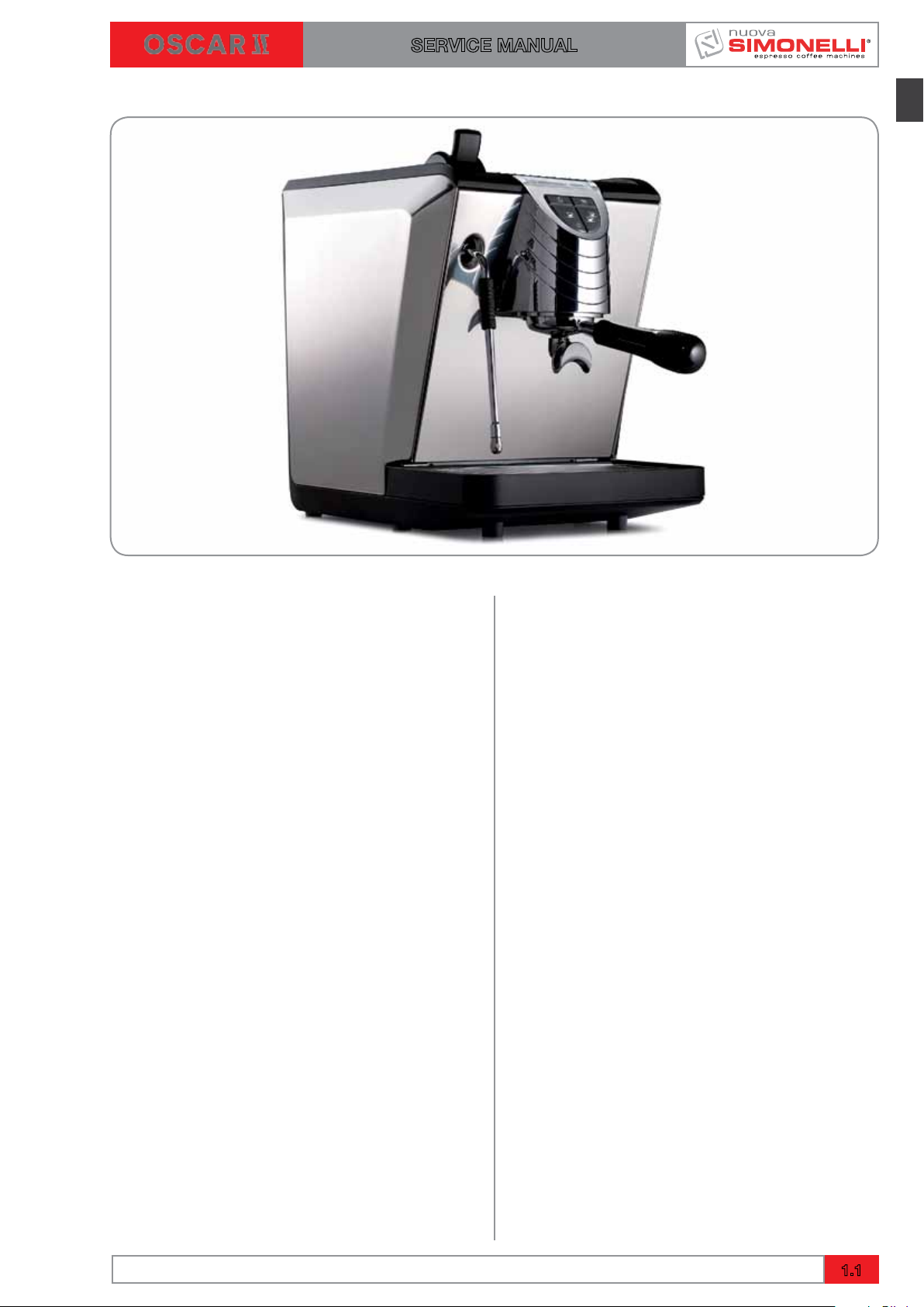
1. MACHINE DESCRIPTION
SERVICE MANUAL
INDEX
1. MACHINE DESCRIPTION ........1.1
1.1 DESCRIPTION ...................1.2
1.2 KEYBOARD DESCRIPTION
(Standard configuration)...........1.3
1.3 SAFETY REGULATIONS ...........1.4
1.4 MACHINE IDENTIFICATION ........1.7
1.5 TRANSPORT ....................1.8
1.5.1 HANDLING ..................1.8
Ed. 02 of 09/2016
1.1
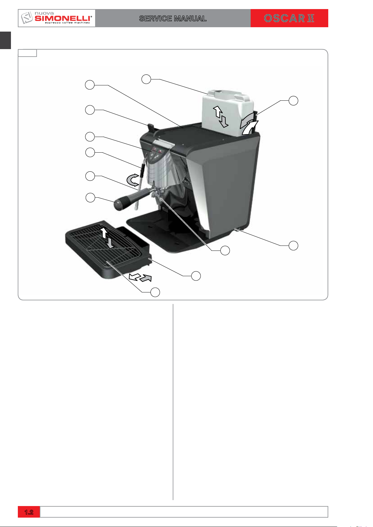
1.1 DESCRIPTION
Fig. 1
SERVICE MANUAL
12
11
10
2
1
9
3
4
6
5
LEGEND
1 Steam lever
2 Cup warming grill
3 Water reservoir
4 Water reservoir hatch
5 Main switch
6 Dispensing unit
7 Water drain tank
8 Cup support grill
9 Filter holder
10 Steam wand
11 Steam wand insulating rubber
12 Control panel
7
8
1.2
Ed. 02 of 09/2016
SERVICE MANUAL
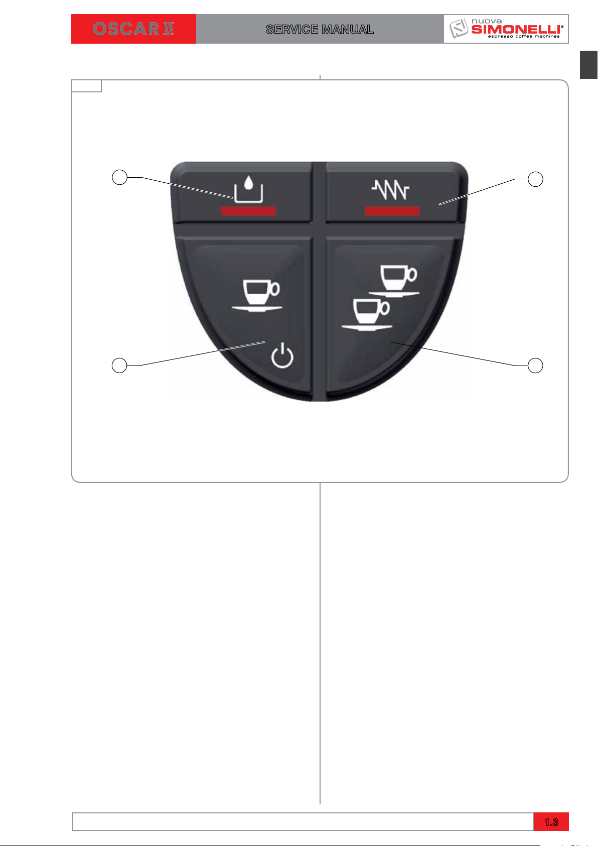
1.2 CONTROL PANEL DESCRIPTION (Configuration standard)
Fig. 2
1
4
2
3
LEGEND
1 Water level warning light
2 Heating resistance on warning light
3 Two coffee dispensing button / programming
entry
4 One coffee dispensing button / Standby
Ed. 02 of 09/2016
1.3
SERVICE MANUAL
1.3 SAFETY INDICATIONS
The present manual is an integral and essential part of the product and is to be delivered
to the user. Carefully read all warnings in
the manual as they provide important information required to install, use and maintain
the unit safely. Keep this manual in a safe
place for further consultation.
After having removed the packaging,
make certain that the unit is not damaged
in any way.
If you have any doubts, do not use the unit
and contact a professionally qualified person. Always keep all packaging (plastic
bags, polystyrene foam, nails, etc..) out of
the reach of children as they are a potential source of danger and never loiter the
environment with such materials.
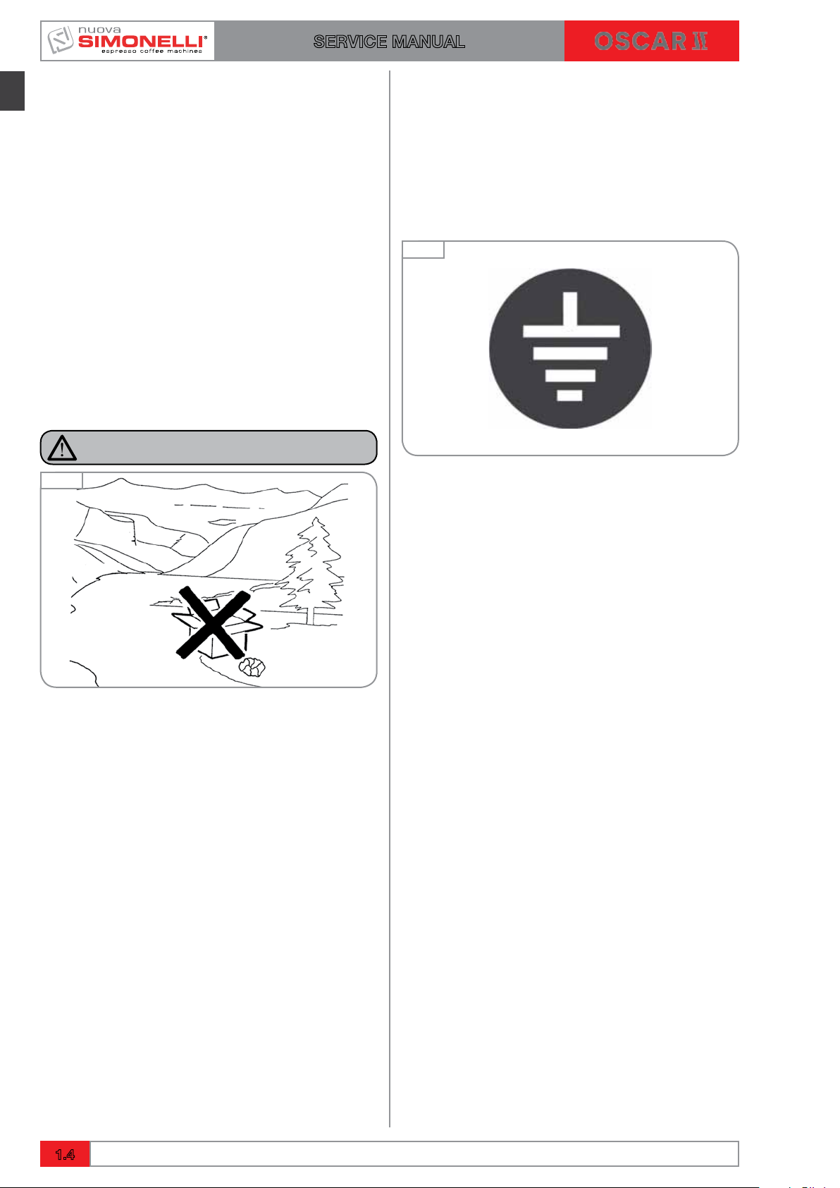
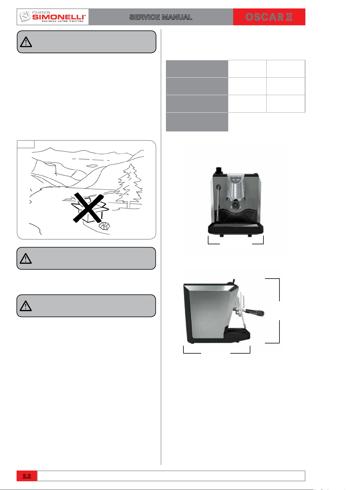
DANGER OF POLLUTION
Fig. 3
The manufacturer cannot be held responsible for any damages incurred if the system is not grounded.
For electrical safety, this machine requires
a ground system. Contact a technically
certified electrician who must check that
the line electrical capacity is adequate for
the maximum capacity indicated on the
unit label.
Fig. 4
The qualified electrician must also check
that the section of the installation’s cables
is large enough for the absorbed power of
the appliance.
Never use adapters, multiple jacks or extension cords. When such items prove absolutely necessary, call in a qualified electrician.
The machine is can be installed in staff
kitchen areas in shops, offices and other
working environments, farm houses by
clients in hotels, motels and other residential type environments bed and breakfast type environments.
Before turning on the unit make certain
that the rating indicated on the label
matches the available power supply. The
nameplate can be seen inside the machine
when removing the water collection tray.
The machine must be installed according
to the applicable federal, state and local
standards (codes) in force with regard
to plumbing systems including backflow
prevention devices. For this reason, the
plumbing connections must be carried
out by a qualified technician.
The warranty expires if the characteristics
of the power supply do not correspond to
the nameplate data.
When installing the device, it is necessary
to use the parts and materials supplied with
the device itself. Should it be necessary to
use other parts, the installation engineer
needs to check their suitability for use in
contact with water for human consumption.
The installer must Make the hydraulic connections respecting the rules of hygiene
and water safety to environmental protection in force in the place of installation. So
for the hydraulic plant contact an authorized technician. Always utilise the new
hose supplied for connection to the water
supply. Old hoses must not be utilised.
The device needs to be supplied with
water that is suitable for human consumption and compliant with the regulations
in force in the place of installation. The
installation engineer needs confirmation
from the owner/manager of the system
that the water complies with the requirements and standards stated above.
This unit must only be used for the purposes described in the present manual.
The manufacturer cannot be held responsible for any damages caused by improper, mistaken and unreasonable use.
1.4
Ed. 02 of 09/2016

OK
SERVICE MANUAL
The appliance is not to be used by children
or persons with reduced physical, sensory
or mental capabilities, or lack of experience and knowledge, unless they have
been given supervision or instruction.
Children must not play with the appliance.
Cleaning and maintenance must not be
carried out by children unless supervised.
This appliance is for professional use only.
The operating temperature must be within
the range of [+5, +35]°C.
At the end of installation, the device is
switched on and taken to rated operating
conditions, leaving it in a state in which it
is “ready for operation”.
After reaching the “ready for operation”
condition, the following dispensing operations are carried out:
• 100% of the coffee circuit through the
coffee dispenser (for more than one
dispenser, this is divided equally);
• Open the steam outlet for 1 minute.
Fig. 5
Fig. 6
At the end of installation, it is good practice to draw up a report of the operations.
CAUTION
Before using the machine, read this manual in its entirety or, at the very least, read
the safety and set up instructions.
There are some basic rules for the use of
any electrical appliance.
In particular:
• Never touch the unit with wet hands or
feet;
• Never use the unit with bare feet;
• Never use extension cords in areas
equipped with baths or showers;
• Never pull on the power supply cord to
unplug the unit;
• Never leave the unit exposed to atmospheric agents (rain, direct sunlight, etc.);
• Never let children, unauthorized personnel or anyone who has not read this
manual operate the unit.
Before performing any sort of maintenance, the authorized technician must
turn off the unit and unplug it from the
mains.
Before cleaning the unit set it in a state of
"0" energy: that is, "MACHINE SWITCHED
OFF AND UNPLUGGED". Follow the
instructions given in this manual carefully.
Refer to chapters 6 and 7 for periodical
cleaning and maintenance. The authorized technician must, before carrying out
any maintenance, disconnect the plug
after the switch off of the machine.
In case of breakdown or poor function,
turn off the unit. Never tamper with the
unit. Contact only professionally qualified
personnel.
Only the manufacturer or an authorized
service center can make repairs and only
using original spare parts.
Non compliance with the above can compromise machine safety.
On installation, the qualified electrician
must fit a circuit breaker switch as foreseen by the safety norms in force that has
a contact open distance that permits the
complete disconnection under conditions
of overload category III.
Ed. 02 of 09/2016
1.5
SERVICE MANUAL
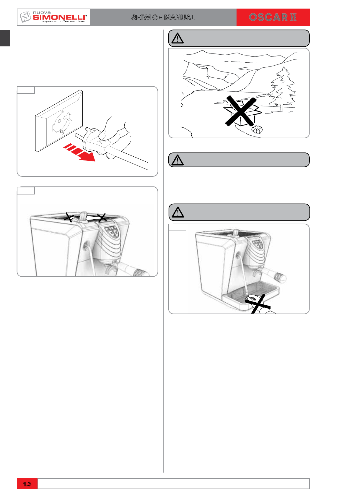
To prevent dangerous overheating, it is
advisable to fully extend the power supply
cord.
Never block the intake and/or heat dissipation grills, in particular those for the
cup warmer.
Fig. 7
OK
Fig. 8
WARNING
DANGER OF POLLUTION
Fig. 9
DANGER OF INTOXICATION
Once started the washing machine, do
not interrupt, the detergent residue may
remain inside the delivery unit.
The user must never replace the unit's
power supply cord. If this cord is damaged, turn off the unit and have it replaced
by a professionally qualified technician.
Should it be necessary to replace the
power cord, this replacement operation
must only be performed by an authorized
service centre or by the manufacturer.
Should you decide to stop using this type
of unit, we suggest you render it inoperable by unplugging it and cutting the power
supply cord.
Do not throw the machine in nature for the
Elimination contact an authorized center or
contact the manufacturer who will provide
you the necessary information about it.
Never dispose of the machine in the environment: to dispose of the machine, contact an authorized center or contact the
manufacturer for pertinent indications.
CAUTION
DANGER OF BURNS
Fig. 10
To facilitate aeration of the unit, position
the aeration portion of the machine 15 cm
from walls or other machinery.
Be extremely careful when using the steam
nozzle. Never place your hands under the
nozzle and never touch it right after use.
Remember that to install, maintain, unload
and regulate the unit, the qualified operator must always wear work gloves and
safety shoes.
When adding the coffee, the operator must
never put his hands into the container.
The noise level of the machine is less than
70db.
1.6
Ed. 02 of 09/2016
!
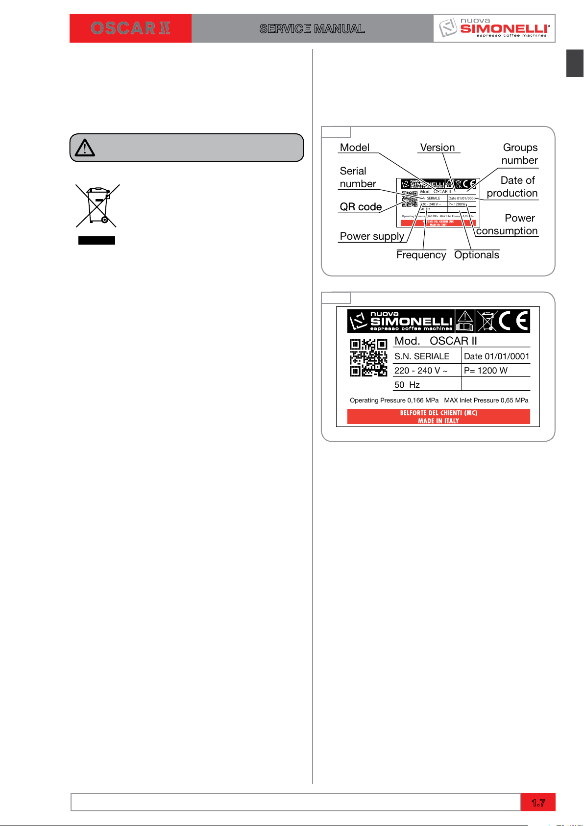
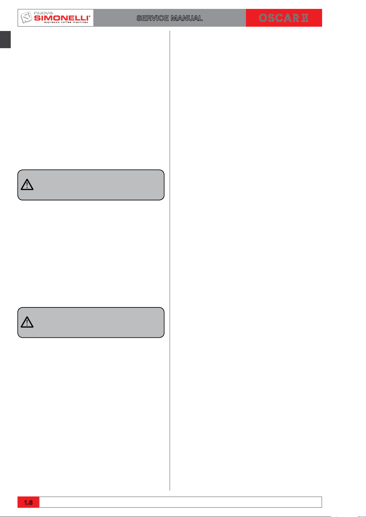
Mod. OSCAR II
S.N. SERIALE
220 - 240 V ~
50 Hz
Operating Pressure 0,166 MPa MAX Inlet Pressure 0,65 MPa
Date 01/01/0001
P= 1200 W
QR code
Version
Model
Serial
number
QR code
Power supply
Frequency Optionals
Groups
number
Date of
production
Power
consumption
!
Mod. OSCAR II
S.N. SERIALE
220 - 240 V ~
50 Hz
Operating Pressure 0,166 MPa MAX Inlet Pressure 0,65 MPa
Date 01/01/0001
P= 1200 W
SERVICE MANUAL
For machines connected to the mains
water supply, the minimum pressure must
be 2 bar and the maximum pressure
for correct machine operation must not
exceed 4 bar.
CAUTION
INFORMATION TO THE USERS
Under the senses of art. 13 of
Law Decree 25th July 2005,
n. 151 "Implementation of the
Directives/Guidelines 2002/95/
CE, 2002/96/CE and 2003/108/
CE, concerning the reduction
of the use of dangerous substances in electric and electronic equipment, as well as
the disposal of wastes".
1.4 MACHINE IDENTIFICATION
Always quote the machine serial number in all
communications to the manufacturer, Nuova
Simonelli.
Fig. 11
Fig. 12
The symbol of the crossed large rubbish container that is present on the machine points out
that the product at the end of its life cycle must
be collected separately from the other wastes.
The user for this reason will have to give the
equipment that got to its life cycle to the suitable
separate waste collection centres of electronic
and electro-technical wastes, or to give it back
to the seller or dealer when buying a new equipment of equivalent type, in terms of one to one.
The suitable separate waste collection for the
following sending of the disused equipment to
recycling, the dealing or handling and compatible environment disposal contributes to avoid
possible negative effects on the environment and
on the people's health and helps the recycling of
the materials the machine is composed of. The
user's illegal disposal of the product implies the
application of administrative fines as stated in
Law Decree n.22/1997” (article 50 and followings
of the Law Decree n.22/1997).
The machine internet page can be accessed
directly through the QR code.
By downloading and installing one of the apps to
read such codes on a mobile device.
Start the app and position the camera in front of
the code so that it can be clearly seen.
Wait some time while the app processes the result
and shows the internet page of the machine on
the display.
Ed. 02 of 09/2016
1.7
SERVICE MANUAL
1.5 TRANSPORT
The machine is transported on pallets which
also contain other machines - all boxed and
secured to the pallet with supports.
Before carrying out any transport or handling
operation, the operator must:
• putonworkglovesandprotectivefootwear,
as well as a set of overalls which must be
elasticated at the wrists and ankles.
The pallet must be transported using a suit-
able means for lifting (e.g., forklift).
1.5.1 HANDLING
WARNING
COLLISION OR CRUSHING HAZARD
During the entire handling operation, the operator must make sure no one or nothing is inside
the operating area.
Slowly lift the pallet to about 30 cm from the
ground and move to the loading area. After
making sure there are no obstacles, persons or
things, proceed with loading.
Once at destination, always using an adequate
lifting mechanism (e.g. fork-lift), after making
sure there is no one or nothing within the unloading area, lower the pallet to about 30 cm from the
ground and transport it to the storage area.
WARNING
COLLISION OR CRUSHING HAZARD
Before performing the following operation, make
sure the load is in place and is not likely to fall
when the straps are cut.
The operator, wearing safety gloves and footwear, must now cut the straps and store the
product. To perform this operation, check the
technical characteristics of the product to determine the weight of the machine to be stored and
take consequent precautions.
1.8
Ed. 02 of 09/2016

SERVICE MANUAL
2. FIRST INSTALLATION AND PRELIMINARY OPERATIONS
INDEX
2. FIRST INSTALLATION AND
PRELIMINARY OPERATIONS .....2.1
2.1 FIRST INSTALLATION .............2.2
2.1.1 WEIGHT AND DIMENSIONS ....2.2
2.1.2 CONNECTION TO THE
WATERLINE AND DRAINAGE
SYSTEM ....................2.3
2.1.3 TECHNICAL SPECIFICATIONS..2.4
2.1.4 CONNECTION TO THE POWER
LINE .......................2.4
2.1.5 PROCEDURE OF FIRST
INSTALLATION...............2.4
2.2 ACCESSORIES BOX . . . . . . . . . . . . . . 2.5
2.2.1 FITTING THE FILTER HOLDER..2.5
2.3 PROGRAMMING DOSES ..........2.6
Ed. 02 of 09/2016
2.1
2.1
SERVICE MANUAL
RISK OF POLLUTION
DO NOT DISPOSE PACKAGING in the environment.
2.1 FIRST INSTALLATION
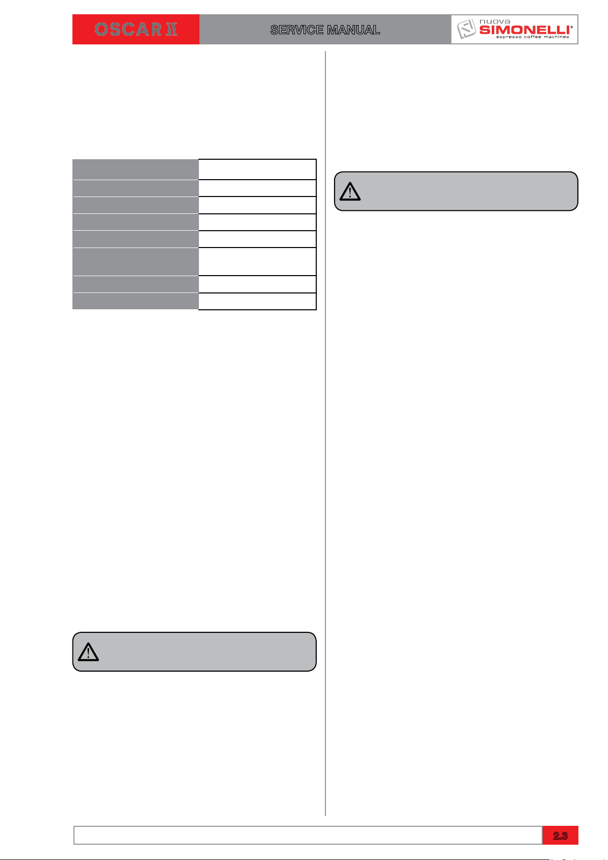
2.1.1 WEIGHT AND DIMENSIONS
NET WEIGHT 14 kg 31 lb
Prior to installation please carefully read the
safety instructions in this manual. The company
cannot be held responsible for damage to persons or property arising from non-compliance
with safety regulations, either during installation
or maintenance of the machine described in this
manual.
Fig. 13
GROSS WEIGHT 17 kg 37 lb
POWER 1200 W 1200 W
DIMENSIONS
A
300 mm 12”
WARNING
Place the machine in an area where all risks of
malfunction can be avoided.
WARNING
Never install in areas where the machine may
be subject to jets of water.
C
400 mm
15,8”
B
408 mm
16”
2.2
Ed. 02 of 09/2016
SERVICE MANUAL
2.1.2 CONNECTION TO THE WATERLINE
AND DRAINAGE SYSTEM
The machine requires stringent specifications to
prevent the formation of limescale and to ensure
quality beverages. The main features required to
achieve high standards of performance are the
following:
Total hardness
50 -60 ppm
Waterline pressure 2-4 bar, cold water
Minimum flow 200 l/hr
Filtration Less than 1.0 micron
Alkalinity
Total dissolved salts
10-150 ppm
50 -100 mg/L
(TDS)
Chloride < 0.5 mg/L
pH 6.5- 8.5
It is the task of a qualified technician to:
1 Adapt the water from the waterline to the
specifications required using filters and
water softeners;
2 Train the final user so that the equipment for
water treatment is constantly kept perfectly
operational.
The version with direct coupling is provided with
a loading tube 1,5 meters long with a 3/4 inch.
On one side is the fitting is straight and tapered,
the other angled at 90° with a gasket. The tube
is provided with tapered fittings therefore it is not
necessary to use Teflon tape on the fitting.
WARNING
If the water features do not comply, the warranty will automatically expire.
To connect the machine to the waterline, proceed as follows:
1 Remove the pipe from the upper door “A”
and connect one of its ends to fitting “B”
situated on machine base.
2 Connect the other end of the pipe to the
waterline using a 3/8 fitting.
NOTE
Dirty water drainage is carried out through the
drip tray both for version with connection to the
waterline and with tank.
Ed. 02 of 09/2016
2.3
SERVICE MANUAL
2.1.3 TECHNICAL SPECIFICATIONS
The machine is available in the following versions:
• single-phase 120 V 60 Hz (tank and waterline)
• single-phase 230 V 50 Hz (tank and waterline)
• single-phase 230 V 60 Hz (waterline)
The relative power absorbed is indicated on the
machine plate.
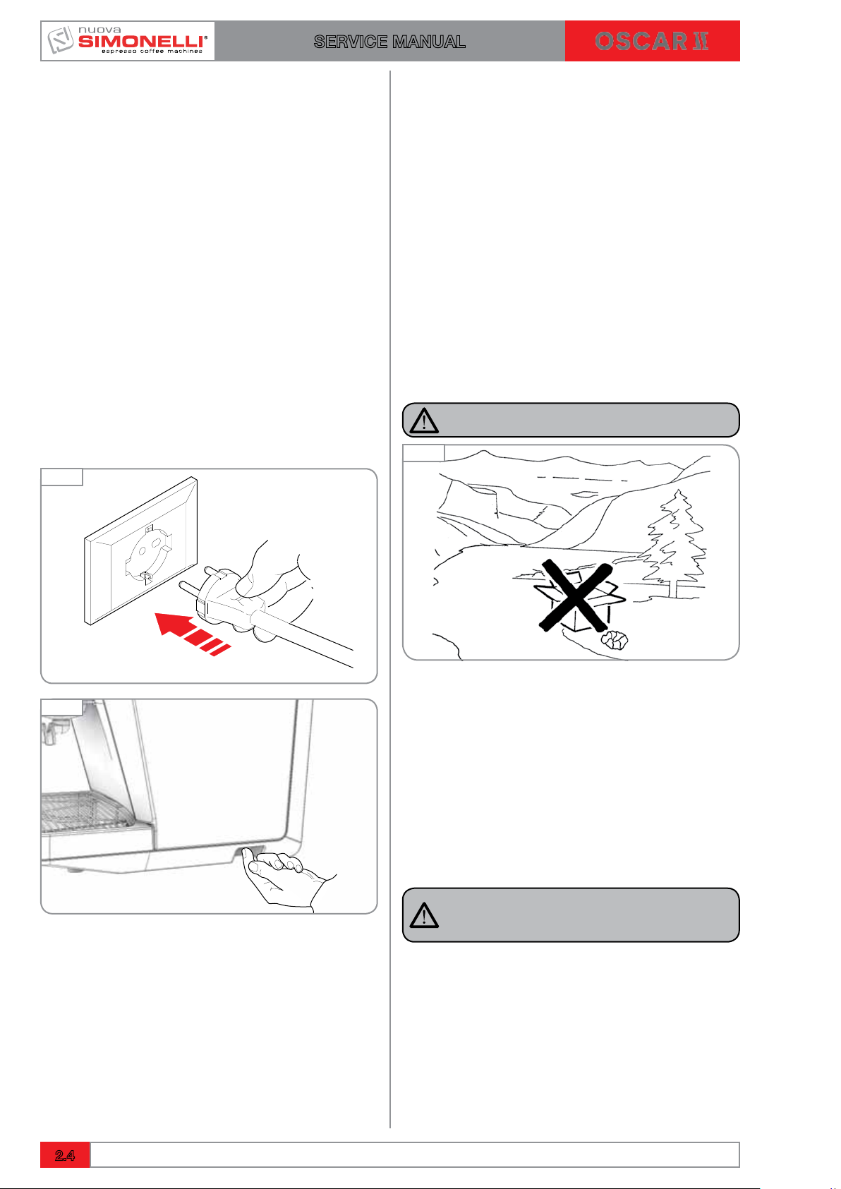
2.1.4 CONNECTION TO THE POWER LINE
Before utilising the machine, the operator must
have read and fully understood the safety instructions in this manual.
Connect the machine to the power socket.
The machine carries out the following checks.
Fig. 14
2.1.5 PROCEDURE OF FIRST
INSTALLATION
Before carrying out the installation carefully read
the safety instructions at the beginning of this
manual and particularly about how to put THE
MACHINE INTO ZERO ENERGY STATUS.
1 Once the machine has been removed from
the packaging, position it on a horizontal
surface and proceed with the installation as
illustrated in the following paragraphs.
Arrange the accessories as follows:
2 Insert the ring in its seat inside the filter
holder.
3 Insert one of the two filters.
4 Caution: danger of pollution.
DANGER OF POLLUTION
Fig. 16
Fig. 15
OK
Tank Model:
5 Open the hatch and take out the reservoir.
Especially the first time, wash the reservoir
with soap and water. Fill the reservoir with
water and make certain that the outside of
the reservoir is dry.
6 Return the reservoir to its housing and close
the hatch.
7 Make certain that the water drain tank has
been inserted.
NOTE
If the machine does not have enough water in the
tank or the pump stays on for more than 90 seconds, the machine will stop and all the buttons
flash. Getting on and off the machine: operation
of the filling boiler will run until the appropriate
level.
2.4
Ed. 02 of 09/2016
SERVICE MANUAL
NOTE
In the absence of load water at first boot:
1 Could be created air bubble between the
pump and reservoir and is preventing the
passage of water.
2 Make sure that the tank valve is working.
3 Remove and replace the tank filled with
water several times to facilitate removal of
the air bubble.
Direct attachment version:
5 Open the door of the tank and remove the
hose for direct attachment.
6 Connect the hose to the water supply and
open the tap upstream of the machine if present.
7 Make certain that the water drain tank has
been inserted.
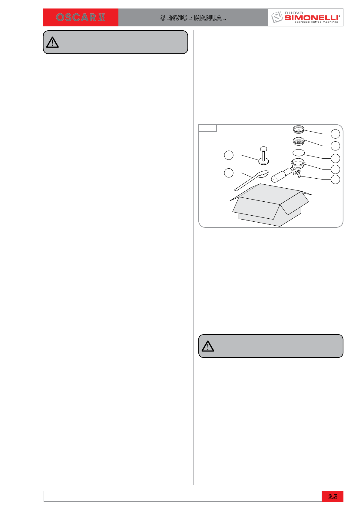
2.2 ACCESSORIES BOX
Machine is supplied with an accessories box
consisting of:
1 Single filter
2 Double filter
3 Spring
4 Filter holder
5 Dispensing nozzle
6 Coffee doser
Fig. 17
7
6
1
2
3
4
5
Make certain that the cup support grill is positioned squarely and is level:
8 Check that the steam lever is closed.
9 Make certain that the line voltage corre-
sponds to the requirements indicated on the
label.
10 The preliminary operations have been com-
pleted and the machine is ready to be set up.
2.2.1 FITTING THE FILTER HOLDER
To properly mount the filter holder:
1 Insert the spring inside the pay slot inside
the filter holder.
2 After selecting the appropriate filter (1 or 2),
insert the filter in the filter holder until you
hear the snap with spring.
3 Screw the dispensing spout up to place it
perpendicular to the handle.
NOTE
To change the filter inserted, pry up the edge with
one of the other filters.
Ed. 02 of 09/2016
2.5
SERVICE MANUAL
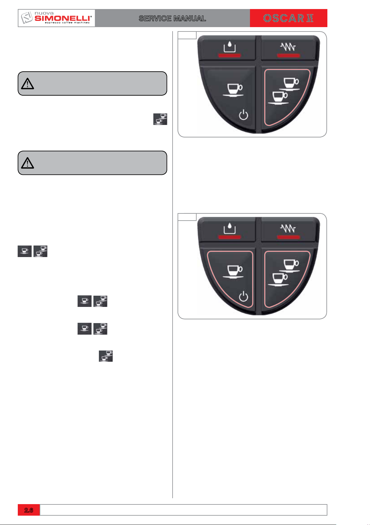
2.3 PROGRAMMING DOSES
Carry out the following operations to enter into
programming mode:
NOTE
Operation to be carried out with the machine
switched on.
To enter into programming mode, press the
two coffee dispensing button for 5 seconds.
The dispensing buttons start to flash.
NOTE
After 30 seconds of inactivity (no buttons pressed)
in programming mode, the machine returns to
normal mode and no data is memorised.
Fig. 18
PROGRAMMING COFFEE DOSES
To programme the dose of water relative to one of the
dispensing buttons, proceed as follows:
Fill the filter holder with the correct dose of coffee (the
filter holder can be single or double depending on the
button to be programmed).
Place the filter holder into the unit.
Press one of the dispensing buttons.
Dispensing starts; once the desired quantity has been
reached press the same button again.
To exit from the programming mode and memorise
the desired doses, keep the
at least 5 seconds; the buttons stop flashing.
button pressed for
Fig. 19
2.6
Ed. 02 of 09/2016
SERVICE MANUAL
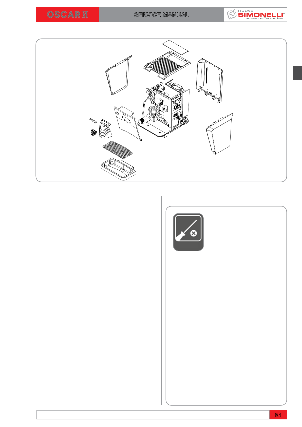
3. REMOVAL OF THE EXTERNAL SURFACE
INDEX
3. REMOVAL OF THE
EXTERNAL SURFACE ...........3.1
3.1 REMOVAL OF WATER TANK .......3.2
3.2 REMOVAL OF THE CUP
HOLDER SURFACE...............3.3
3.3 REMOVAL OF THE SIDE PANELS ...3.4
3.4 REMOVAL OF THE REAR PANEL ...3.4
3.5 TANK TO COLLECT WATER FILED ..3.4
3.6 REMOVAL OF THE FRONT PANEL ..3.5
3.6.1 REMOVAL OF KEYBOARD .....3.6
TOOLS NEEDED:
Ed. 02 of 09/2016
3.1
CUTTING
AND
HOT
SURFACES
SERVICE MANUAL
DANGER
Use gloves to protect against sharp or hot
surfaces that you can bump against involuntarily during operations.
NOTE
Before proceeding with the removal of the
panels it is advisable to clean and free up
enough space where the machine parts will
rest so that they are not be unintentionally
damaged.
DANGER
Before proceeding with the operations
described in the chapter make sure that the
machine is turned off and unplugged from the
mains. Discharge any residual pressure present in the heater.
Fig. 22
Fig. 23
DANGER
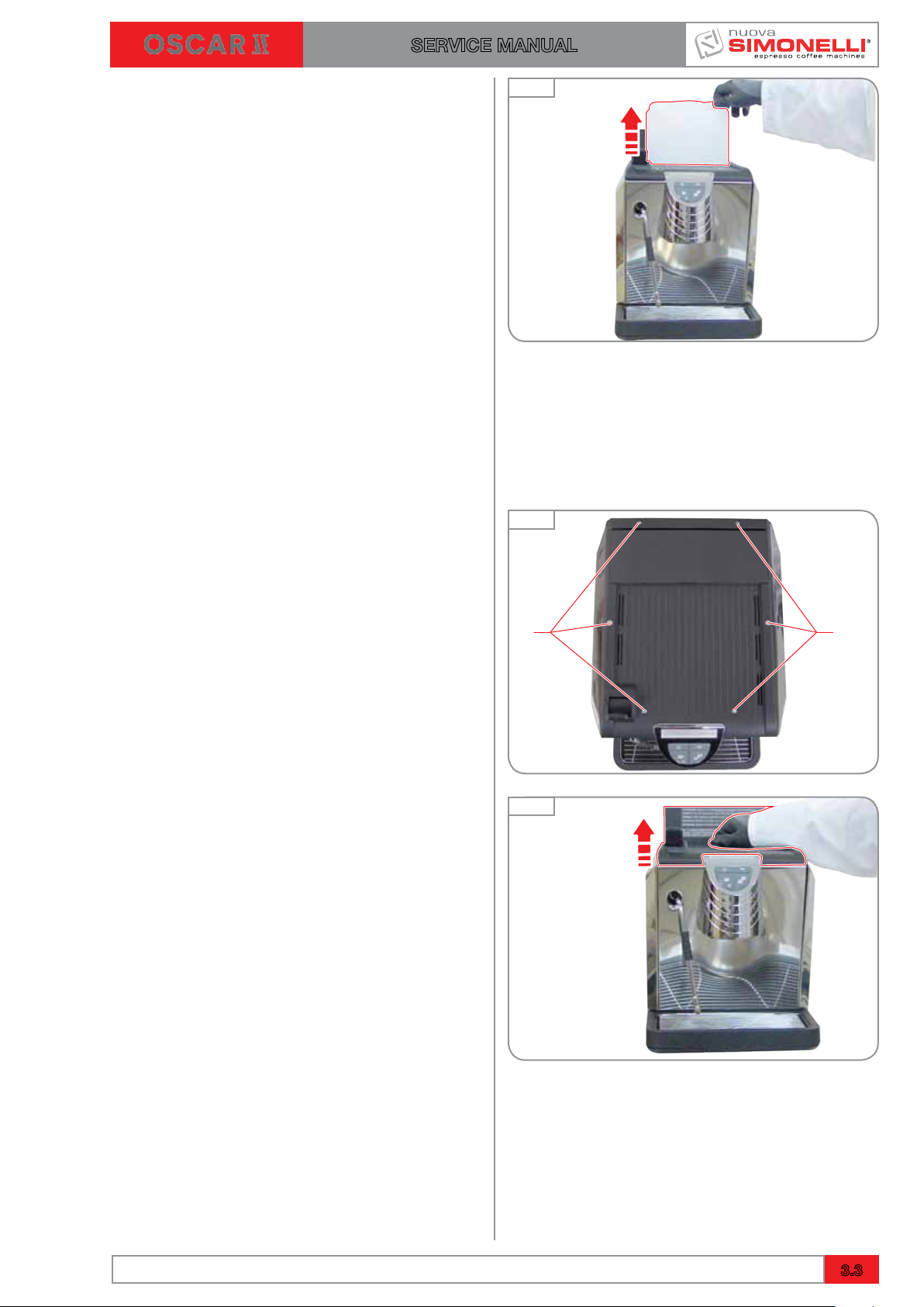
3.1 REMOVAL OF WATER TANK
To remove machine covers, take out the water
tank first:
NOTE
This operation is necessary only for the version with tank.
To remove the tank from its seat, proceed as follows:
1 Lift the water tank cap.
Fig. 22
3.2
Ed. 02 of 09/2016
A A
SERVICE MANUAL
2 Pull the water tank upward.
3.2 REMOVAL OF THE CUP HOLDER
SURFACE
To remove the bearing surface of the cup, proceed as follows:
1 Unscrew the screws "A" with a screwdriver.
Fig. 23
Fig. 24
2 Lift the panel and pull upwards.
Fig. 25
Ed. 02 of 09/2016
3.3
2
1
2
1
A
A
2
1
SERVICE MANUAL
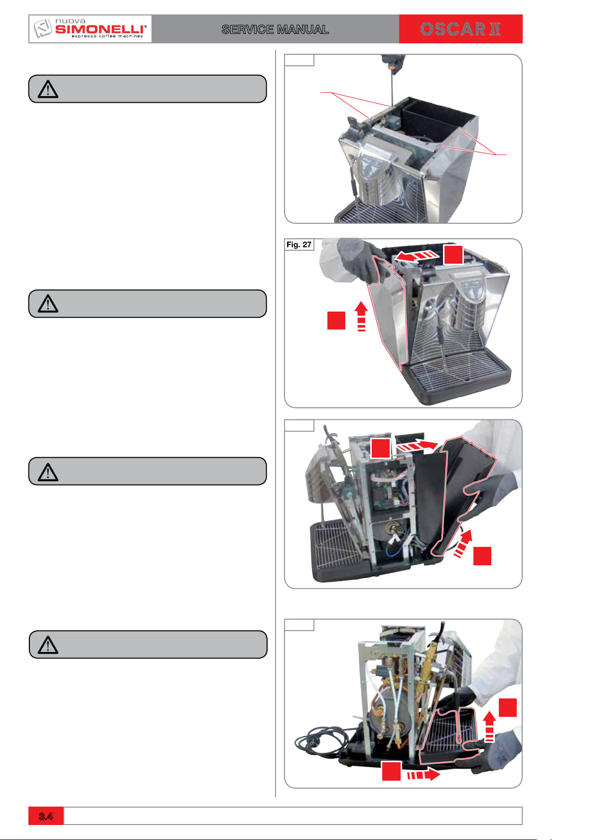
3.3 REMOVAL OF THE SIDE PANELS
NOTE
To remove the side panels, it is necessary to
remove the cup holding surface first.
1 Unscrew the "A" present on each panel
using a Phillips screwdriver.
2 Move outside the top of the panel and pull
up.
NOTE
Perform the same steps for the other side
panel.
Fig. 26
Fig. 27
3.4 REMOVAL OF THE REAR PANEL
NOTE
To remove the back panel it is necessary to
remove both side panels first.
Proceed as follows:
1 Move outside the top of the panel and pull
up.
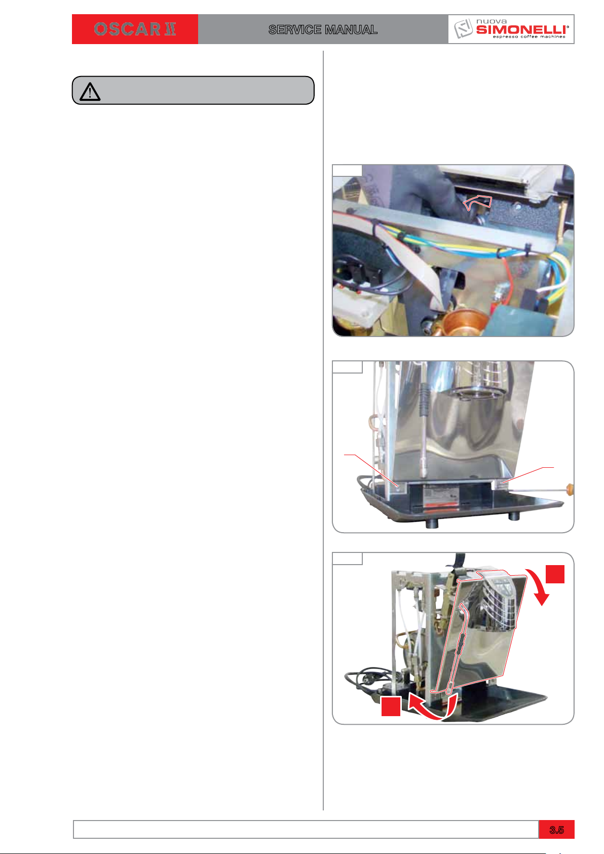
3.5 TANK TO COLLECT WATER FILED
NOTE
To remove the tray with water you need:
1 Lift and remove the tray with water.
Fig. 28
Fig. 29
3.4
Ed. 02 of 09/2016
A
A
1
2
SERVICE MANUAL
3.6 REMOVAL OF THE FRONT PANEL
NOTE
To remove the front panel, you must remove
the top panels and water from the drain pan.
1 Disconnect the connection to the panel.
2 Unscrew the screws "A" with a Phillips
screwdriver.
Fig. 30
Fig. 31
3 Slight outside the steam nozzle, then slide
the front panel to the front of the machine.
Ed. 02 of 09/2016
Fig. 32
3.5
A
1
SERVICE MANUAL
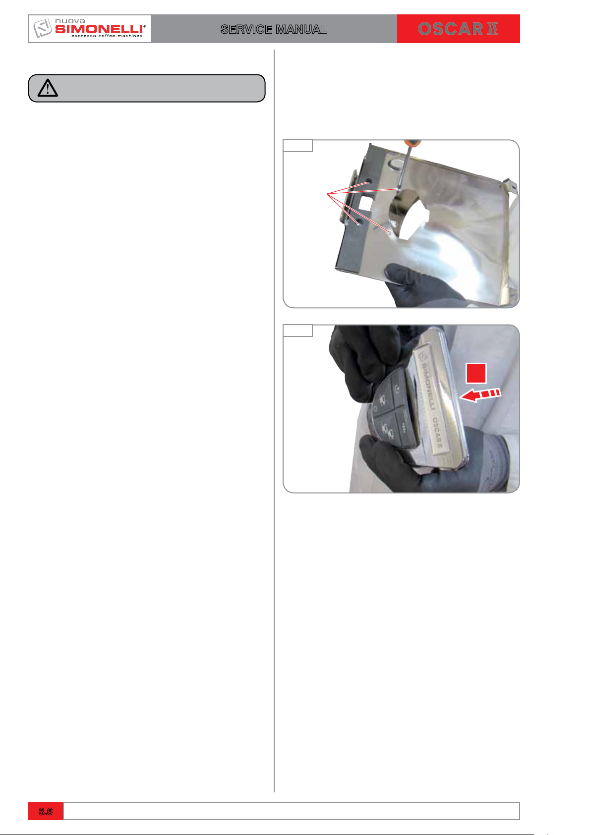
3.6.1 REMOVAL OF KEYBOARD
NOTE
Separate the cover unit from the front panel.
1 Loosen the 4 screws “A” situated on the
back of the front panel using a Phillips
screwdriver.
2 Push in the connector located inside of the
support group to detach the panel.
Fig. 33
Fig. 34
3.6
Ed. 02 of 09/2016

4. INFUSION UNIT
SERVICE MANUAL
INDEX
4. INFUSION UNIT ................4.1
4.1 REMOVAL OF SHOWER
AND SEAL ..................4.2
4.2 COFFEE VALVE ..............4.3
4.3 EXPANSION VALVE ...........4.5
TOOLS NEEDED:
Ed. 02 of 09/2016
4.1

SERVICE MANUAL
The underpan seal prevents water from coming
out from the sides of the pavilion and reach the
capsule unevenly or spill from the filter holder.
Since the material is plastic and exposed to high
temperatures, replace the seal periodically, at
least once a year or according to machine operation, as it tends to deform, loosening elasticity
and sealing.
4.1 REMOVAL OF SHOWER AND SEAL
To remove the shower and pavilion it is sufficient
to loosen the central screw under the unit.
Fig. 35
Fig. 36
WARNING
If the machine was turned off recently, protect
yourself with thermal insulation gloves.
To change the seal use an awl or a slim flathead
screwdriver and at first remove one edge of the
seal and then remove it entirely.
If the unit is worn out just insert shims under the
seal so as to reduce the stroke of the filter holder.
Fig. 37
Fig. 38
4.2
Ed. 02 of 09/2016

SERVICE MANUAL
4.2 COFFEE VALVE
It is a solenoid valve that is normally closed and
opens when it received a command to dispense
coffee.
By closing the decompression removes any
excess water from the filter holder.
TYPICAL PROBLEMS
Check the operation of the valve, if the unit continues to drip continuously or if the coffee capsule is too wet.
Possible causes:
1 First check if the frame is too thin.
2 The third passage of the valve is obstructed,
therefore the final suction is less than it
should be.
3 Shower and pavilion are blocked because of
poor machine cleaning.
Fig. 39
DANGER
Before proceeding with the operations
described in the chapter make sure that the
machine is turned off and unplugged from the
mains. Discharge any residual pressure present in the heater.
HOW TO REPLACE THE COFFEE VALVE:
To remove the coffee valve proceed as follows:
1 Remove the right, side panel and the front
one, as explained in Chapter 3.
2 Disconnect power connections.
3 Disconnect the Teflon tube by removing the
cable holder “A” using the pliers.
Fig. 40
Fig. 41
Ed. 02 of 09/2016
4.3

B
A
C
SERVICE MANUAL
4 Remove the washer and the locking nut “B”
using a 14 mm wrench.
Remove the coil.
5 Loosen the coil support “C” with a 24 mm
wrench.
Fig. 42
Fig. 43
6 Use a 3 mm Allen key to remove the two
screws that fix the head to the unit.
Remove lime scale or oily residues that may
block the free circulation of water.
NOTE
In case of oily residues, properly instruct the
staff using the machine to perform a regular,
deep cleaning with suitable detergents.
Fig. 44
Fig. 45
4.4
Ed. 02 of 09/2016

A
SERVICE MANUAL
4.3 EXPANSION VALVE
To remove the expansion valve, proceed as follows:
1 Remove the front panel.
2 Disconnect the Teflon tube by removing the
cable holder “A” using the pliers.
Fig. 46
3 Loosen the valve with a 14 mm wrench.
4 Apply Teflon tape on the new valve before
screwing it.
Fig. 47
Fig. 48
Ed. 02 of 09/2016
4.5

SERVICE MANUAL
4.6
Ed. 02 of 09/2016

5. HEATER
SERVICE MANUAL
INDEX
5. HEATER.......................5.1
5.1 EMPTYING THE HEATER . . . . . . . . . . 5.2
5.2 REMOVAL OF THE HEATER ........5.4
5.3 HEATING ELEMENT AND
HEAT PROTECTION ..............5.5
5.4 REPLACEMENT OF THE
LEVEL GAUGE ...................5.6
5.5 ANTIVACUUM VALVE .............5.7
5.6 SAFETY VALVE ..................5.8
TOOLS NEEDED:
30 MM
19 MM
Ed. 02 of 09/2016
16 MM 12 MM 12 MM
5.1

A
SERVICE MANUAL
5.1 EMPTYING THE HEATER
DANGER
Before proceeding with the operations
described in the chapter make sure that the
machine is turned off and unplugged from the
mains. Discharge any residual pressure present in the steam heater.
WARNING
Before carrying out the heater emptying procedure, remove water inlet sources inside the
waterline:
• Waterline version: close the water inlet
tap and disconnect the pipe.
• Tank version:removethe tankfrom its
seat.
These operations are necessary to avoid any
water leakage inside the machine that may
cause damage.
Fig. 49
DANGER
Fig. 50
WARNING
Every time you work directly.
With the heater it is important to ensure that
the internal pressure is zero. Completely
remove the water inside for operations that
require it.
To empty the heater proceed as follows:
1 Turn off the machine and let out all the steam
by opening fully the steam outlets to lower
the temperature quickly.
2 Remove covers:
• Sidepanels;
• Rearpanel;
• Frontpanel.
3 Place the machine on the right side to pre-
vent water leakage and loosen the drain nut
“A” using a 13 mm wrench.
Fig. 51
Fig. 52
5.2
Ed. 02 of 09/2016

A
4 Connect the drain pipe and tilt the machine
on the left side to let the water out of the
heater.
5 After drainage of water from the heater,
tighten the drain nut “A” using a 13 mm
wrench.
Fig. 53
Fig. 54
Ed. 02 of 09/2016
5.3

B
B
A
C
SERVICE MANUAL
5.2 REMOVAL OF THE HEATER
In case of need, to remove the heater, it is necessary to discharge pressure.
Then, proceed as follows:
1 Remove machine covers:
• Rearpanel;
• Sidepanels;
• Frontpanel.
2 Empty water heater, as in the previous
section.
3 Disconnect the level probe.
4 Disconnect the pressure gauge capillary.
5 Remove the fittings on the upper part of the
heater with a 17 mm wrench:
A SteamNozzle;
B Coffeedeliverygroup;
C HotWaterNozzle.
6 Remove the remaining fittings that hold the
heater in place.
7 Remove the fittings on the left side:
A using a 12 mm wrench.
The heater can be extracted from the machine.
During the assembly phase of the new boiler, pay
close attention to the restoration of the connections to ensure proper operation.
Fig. 55
Fig. 56
5.4
Ed. 02 of 09/2016

B
B
C
A
B
5.3 HEATING ELEMENT AND
HEAT PROTECTION
To access the heating element, remove the right
panel of the cover.
The visible parts are:
A 167° heat protection.
B Electrical connections of heating element.
OSCARIIheaterfeaturesa1200Wheatingelement.
To remove the heating element, proceed as follows:
1 Empty the heater as described above.
2 Loose the nut “A” using a 30 mm wrench.
Fig. 57
3 Remove with care the panel out of its slot.
NOTE
Each time you replace the heating element,
it is also necessary to change the O-ring “B”,
which insulates it from the heater, as it is a
part subject to wear. This component must be
ordered along with the heating element.
Fig. 58
Fig. 59
Ed. 02 of 09/2016
5.5

A
B
SERVICE MANUAL
5.4 REPLACEMENT OF THE
LEVEL GAUGE
Water inside the heater is kept at a constant level
through the use of a level probe.
This probe is connected to the electronic unit,
which continuously checks water level.
Being always exposed to high temperatures and
steam/water it is subject to encrustations which
can inhibit operations.
WHEN TO INTERVENE
• In case it is verified that there are no prob-
lems upstream from the probe you can easily
access the component and perform careful
cleaning with abrasive or descaling agents.
• Make sure the Teflon coatingof the probe is
not damaged. In case of damage, steam leaks
occur and it is necessary to replace the probe.
Fig. 60
Fig. 61
To remove the probe, simply disconnect the red
wire “A” and unscrew the locking bolt “B” with a
16 mm wrench.
NOTE
When replacing the probe it is necessary to
cover the threads with Teflon tape or liquid
sealant.
Fig. 62
5.6
Ed. 02 of 09/2016

5.5 ANTIVACUUM VALVE
The antivacuum valve ensures that air enters the
heater during the machine cooling phase. In this
way the reduction of water volume due to cooling
does not create decompressions that may give
rise to drawbacks such as the suction of milk
throughthesteamnozzle.
WHEN TO REPLACE
You can assume that there are problems with the
antivacuum valve when water coming out from
heater is dirty.
The bad smell is generated from milk that has
been sucked into the heater.
In these cases the valve is closed and is locked
in this condition.
Fig. 63
If the valve blocked open because of limescale
the signs would be:
A Continuous slight whistling sound coming
from the valve.
B Condensation drops near the valve.
NOTE
We suggest that the valve be replaced annually to ensure proper function and excellent
sealing.
HOW TO REPLACE
Using a 19 mm cup hex wrench unscrew the
valve from its housing.
When inserting the new one, coat the threads
with Teflon tape or with a few drops of Loctite.
Fig. 64
Ed. 02 of 09/2016
5.7

A
A
SERVICE MANUAL
5.6 SAFETY VALVE
The heater safety valve “A” of heater serves to
discharge excess pressure that may form owing
to malfunctioning. The valve opens automatically
when inner pressure of heater exceeds 2.1 bar.
WHEN TO REPLACE
For safety reasons each time the valve comes
into operation it should be replaced to ensure
perfect operation.
Therefore, in case of heater flooding or excess
of steam, secure the machine by replacing the
entire valve.
HOW TO REPLACE
Remove the safety valve “A” by unscrewing it
with a 14 mm hex wrench.
Fig. 65
Fig. 66
5.8
Ed. 02 of 09/2016

6. HYDRAULIC CIRCUIT
SERVICE MANUAL
INDEX
6. HYDRAULIC CIRCUIT ...........6.1
6.1 PUMP DISASSEMBLY .............6.2
6.2 REPLACING THE COFFEE VALVE ...6.4
6.3 STEAM NOzzLE .................6.6
6.4 WATER TANK ...................6.11
6.4.1 REPLACEMENT OF
THE FLOAT.................6.11
6.4.2 REMOVAL OF THE
MAGNETIC SENSOR.........6.12
6.5 REMOVAL OF THE PRESSURE
SWITCH .......................6.12
TOOLS NEEDED:
Ed. 02 of 09/2016
6.1

A
SERVICE MANUAL
WARNING
Before carrying out the disassembly procedure of the hydraulic circuit, close water inlet
sources inside the waterline:
• Waterline version: close the water inlet
tap and disconnect the pipe.
• Tank version: remove the tank from its
seat.
Theseoperationsarenecessarytoavoidany
water leakage inside the machine that may
cause damage.
6.1 PUMP DISASSEMBLY
The pump is situated on machine bottom.
The duration depends on the amount of daily
work and the quality of water.
WHEN TO REPLACE THE PUMP
1 During delivery, no water comes out of the
unit.
2 In case the machine remains inactive for too
long, the pump does not delivers owing to
oxidation of fittings.
3 Continuous overheating even in the pres-
ence of water.
If the pump needs to be removed, it is necessary
to:
1 Remove the side and rear panels.
Fig. 67
2 Release the pump from its seat by loosening
the screws “A” of the bottom panel with a
Phillips screwdriver.
6.2
Fig. 68
Ed. 02 of 09/2016

C
D
B
A
SERVICE MANUAL
3 Disconnect the electrical connections of the
pump using the tweezers:
A: temperature probe.
B: power supply.
4 Disconnect the hydraulic connections of the
pump:
• Fromtheflowmeter,disconnecttheTeflon
pipe “C”.
• From the pump to the heater, unscrew
the fitting “D” using a 13 mm spanner.
Fig. 69
Flowmeter
Heater
Fig. 70
5 Take the pump out of the machine.
NOTE
Check the water inlet filter situated in the
heater connection and replace it, if necessary.
NOTE
When replacing the pump, replace the O-ring
code No. 02280007.V, too (see tables at the
end of the manual).
Ed. 02 of 09/2016
6.3

A
B
C
SERVICE MANUAL
6.2 REPLACING THE COFFEE VALVE
The coffee valve “A” is situated underneath the
upper panel, on the left side, and regulates the
amount of water flowing inside the heater during
all phases of machine operation.
WHEN TO INTERVENE
1 The system detects the absence of water
and the pump is set off but the pump sounds
like it’s straining badly: the valve is stuck.
2 There is a general short circuit: the coil may
be short-circuited due to micro leaks or electrical shock.
3 The heater flooded: the impurities have pre-
vented the valve from closing properly.
Fig. 71
HOW TO REPLACE THE COFFEE VALVE
To remove the coffee valve, it is necessary to:
1 Disconnect power connections using twee-
zers "B".
2 Using a 14 mm wrench, remove the bolt "C”
that holds the coil in place and ease it out
of its housing. Under optimal conditions,
the removal is immediate but if parts are
blocked, force removal as much as possible.
Fig. 72
6.4
Ed. 02 of 09/2016

D
E
C
SERVICE MANUAL
3 Using a 24 mm wrench, remove the fixed
part “C“.
4 Disconnect the hydraulic connections “D”
by using a 12 mm wrench.
5 Loose the locking screws “E” to release the
valve from the machine frame.
Fig. 73
Fig. 74
6 Make sure the plunger is clean and there are
no obstructions. Replace the valve if it is not
working.
Fig. 75
Ed. 02 of 09/2016
6.5

DANGER
SERVICE MANUAL
6.3 STEAM NOzzLE
The steam nozzle is composed of a piston actuated by the knob, which presses on a nut with
spring return. By pressing against the spring it
creates space for the steam to pass.
We suggest to replace the seals that keep the
piston perfectly aligned, every 4-6 months. Every
year it is advisable to replace the nut to prevent
the gasket that insulates the steam from drying
and letting seampass. Since these parts must
be changed, we suggest replacing all the seals
simultaneously.
WHEN TO INTERVENE
Problems related to the steam nozzle are:
• Continuouslossofsteam.
• Waterdrippingfromthesteamnozzle.
• Delayedclosure.
• Steamlevertooloose.
Fig. 76
Fig. 77
DANGER
Before proceeding with the operations
described in the chapter make sure that the
machine is turned off and unplugged from the
mains. Discharge any residual pressure present in the steam heater.
Fig. 78
6.6
Ed. 02 of 09/2016

A
SERVICE MANUAL
If there is a loss of steam or condensation, it is
necessary to:
1 Turn the machine off, let out all the steam
until there is no pressure in the heater.
2 Remove the left side panel and the front one.
3 Loose the steam nozzle by means of the nut
“A” using a 22 mm wrench, by levering the
nozzle locking nut with a 23 mm wrench, as
shown on the figure.
Fig. 79
Fig. 80
4 Loose the steam pipe fitting of the nozzle by
means of a 20 mm wrench, by levering the
locking nut with a 23 mm wrench, as shown
on the figure.
5 Unscrew the locking nut of the steam nozzle
with a 23 mm wrench, by levering the steam
valve block with a 22 mm wrench.
Fig. 81
Ed. 02 of 09/2016
6.7

C
B
2
1
D
A
SERVICE MANUAL
DISASSEMBLY OF THE STEAM LEVER
1 Remove screw "A" with an Allen key 3 mm.
2 Remove the clip "B" using pliers.
3 Pull the lever pin "C" to release the steam
lever "D".
Fig. 82
Fig. 83
4 To remove the dispensing nozzle it is suffi-
cient to unscrew the lower part of the nozzle
by hand. We recommend annual replacement O-ring seals.
MAINTENANCE OF STEAM NOzzLE
To carry out repairs and maintenance once the
steam nozzle is removed we can proceed with
the following steps:
1 Remove the piston which is actuated by the
lever. The seals that make it slide in its housing tend to wear out and must be replaced
depending on the use or every 4-6 months.
Fig. 84
Fig. 85
6.8
Ed. 02 of 09/2016

B
C
A
SERVICE MANUAL
2 Using a 22 mm wrench remove the steam
nozzle from its housing. We recommend
replacing the seal at least once a year.
3 Unscrew the fitting "A" with a 21 mm wrench
to reach the spring.
We recommend replacing the seal at least
once a year.
4 Remove the steam piston "C" behind the
spring "B".
Werecommendreplacingthepistonatleast
once a year.
Fig. 86
Fig. 87
The steam nozzle, in its simplicity, has components that must be replaced due to wear.
It is recommended to replace:
• The piston seals (code No. 02280014) to
avoid misalignment.
• The seals of the leverblock(02280011)and
the connection to the heater.
• Thepistonofinnerclosure(98008004).
RE-ASSEMBLY OF THE STEAM NOzzLE
During the reassembly phase it is important to
lubricate the seals of the piston in contact with
the lever, to ensure fluid movement inside the
housing.
Fig. 88
Fig. 89
Ed. 02 of 09/2016
6.9

A
SERVICE MANUAL
WARNING
Operation to be performed when the machine
is on.
Whenfixingthescrewthatholdstheleveronthe
stream nozzle it is necessary to:
1 Lightly press the lever upwards to let steam
come out.
2 Release the lever until the steam supply
stops.
3 Tighten the lever locking screw on the steam
nozzle.
In this way, there is a precise calibration of the
steam nozzle.
Fig. 90
6.10
Ed. 02 of 09/2016

A
SERVICE MANUAL
6.4 WATER TANK
To access the water tank, remove the rear panel.
NOTE
In case of a prolonged inactivity of the
machine, the tank valve may be blocked
owing to limescale.
To release the tank valve, use a screwdriver to
allow water discharge.
Check the valve for the presence of limescale
and the conditions of seal “A”. Replace the faulty
parts, if necessary.
6.4.1 REPLACEMENT OF THE FLOAT
1 Take out the water tank and remove the rear
panel.
2 Manually remove the tank float.
Fig. 91
Fig. 92
NOTE
During the assembly phase of the new float,
make surethe “+” mark on the float itself is
orientedtowardsthetankbottom.
Ed. 02 of 09/2016
6.11

A
B
SERVICE MANUAL
6.4.2 REMOVAL OF THE MAGNETIC
SENSOR
This sensor serves to detect the presence of
water inside the tank. In case of breakdown or
malfunctioning, it can be replaced.
1 Remove the side and rear panels.
2 Move the sensor down, pay attention to the
electrical connections.
3 Disconnect the sensor unit and replace.
6.5 REMOVAL OF THE PRESSURE
SWITCH
The pressure switch cuts off the circuit powering
the heating element. Therefore, it will read a voltage as the one of mains when heater pressure
is enough, while will read 0V when the heating
element is warming up.
Itisadvisabletoreplacethepressure(pressure)
every two years in order to avoid failure.
You need to replace when:
1 Cardoesnotheat(lightresistancestillis,but
the machine is cold and the heater works).
ThepressureislockedintheOFFstate.
2 The production of the steam engine of water
from the inside, because of the overheating
and the open safety valve. Pressure switch is
lockedintheONstate.
Fig. 93
Fig. 94
To remove the pressure switch “A”, it is necessary to:
1 Remove the right, side panel.
2 Disconnect the electrical connections.
3 Unscrew the fitting “B” with a 17 mm wrench.
Fig. 95
6.12
Ed. 02 of 09/2016

7. ELECTRIC COMPONENTS
SERvICE MaNUaL
INDEX
7. ELECTRIC COMPONENTS .......7.1
7.1 CONTROL UNIT..................7.2
TOOLS NEEDED:
Ed. 02 of 09/2016
7.1

A
A
A
A
2
1
3
4
6
5
7
8
9
10
SERvICE MaNUaL
7.1 CONTROL UNIT
To access the main board it is necessary to:
1 Remove the right side panel.
2 Disconnect the electrical connections using
the pliers.
3 Loosen the board locking screws “A” on the
support using a Phillips screwdriver.
Fig. 96
The control unit without connections appears as
shown in the figure.
1 Tank level
2 Keyboard
3 Heating element
4 The boiler
5 Heating element
6 Neutral
7 Phase
8 Valve group
9 Pump
10 Water level
Fig. 97
7.2
Ed. 02 of 09/2016

1
2
3
8. TROUBLESHOOTING
SERVICE MANUAL
INDEX
8. TROUBLESHOOTING............8.1
8.1 WATER LACK LIGHT..............8.2
8.2 HEATING ELEMENT LIGHT ........8.3
8.4 COFFEE DELIVERY ...............8.4
8.5 STEAM DELIVERY................8.4
8.6 HEATER ........................8.5
Ed. 02 of 09/2016
8.1

8.1 WATER LACK LIGHT
SERVICE MANUAL
Water lack light on. Lack of water in the tank.
Check the magnetic sensor. Replace, if necessary.
Water in the tank.
Float in the tank out of
place or faulty.
Check float positioning. Symbol “+” must
be oriented downward.
Replace, if necessary.
Check connections and
the electronic board.
Replace, if necessary.
Fill the tank with drinkable
water.
8.2
Ed. 02 of 09/2016

8.2 HEATING ELEMENT LIGHT
SERVICE MANUAL
Temperature light in
operating mode off (after
30 min.).
Check the conditions of
the pressure switch and
when locked in the open
state, and replace if necessary.
Check the heating element conditions. Replace,
if necessary.
Check connections and
the electronic board.
Replace, if necessary.
Heat protection on (operating temperature considerably exceeded). Check
the thermal protection and
replace it, if necessary.
The machine emits vapour
from inside the machine
regularly.
Check the status of the
pressure switch make
sure it is locked by measuring a voltage across it at
all times equal to 0V.
Replace the pressure
switch and the safety
valve.
Turn the machine off and
let it cool. Check again if
the offense occurs again.
Recheck pressure switch
and relay resistance of the
unit.
If necessary, replace the
control unit.
Ed. 02 of 09/2016
8.3

8.3 REMOVAL OF KEYBOARD
SERVICE MANUAL
Check connections and
the electronic board.
Replace, if necessary.
8.4 COFFEE DELIVERY
The pump is operating but
there is not water in the
tank.
When pressing the keys,
nothing happens.
Check the keyboard and,
if necessary, replace it.
The machine does not
deliver coffee.
Alarm enabled:
• Lack of water; the corresponding light is on.
• Machine not ready;
operating temperature
not reached; the corresponding light is off.
Check for any problems
due to keyboard.
Check the presence of air
between the tank and the
pump. Remove any limestone residue.
Replace, if necessary.
8.5 STEAM DELIVERY
Check for any problems
due to heater.
When pressing the steam
lever, the machine does
not deliver.
Check the condition of the
steam nozzle Eliminate
any residues of limestone
or milk. Unscrew spout
and if necessary, replace
the nozzle.
Check the shower and, if
necessary, replace it.
Check the presence of
limestone in the Gigler,
in the upper part of the
group.
Check for any problem
arising from heater warming up.
8.4
Ed. 02 of 09/2016

8.6 HEATER
SERVICE MANUAL
With the water tank full,
there is no water in the
heater.
Check the coffee valve.
Replace, if necessary.
Check the tank valve.
Remove any limestone
residue. Replace, if necessary.
Check the pump and, if
necessary, replace it.
When reaching the operating temperature.
The boiler emits more
noise than necessary.
Check the status of the
expansion valve. If necessary, replace.
Check the condition of the
safety valve. If necessary,
replace.
Odour from the heater.
Check the anti-vacuum
valve and, if necessary,
replace it.
If need be, carry out a
complete washing of the
heater with citric acid.
Check the valve and the
level probe. Replace, if
necessary.
Heat protection on (operating temperature considerably exceeded). Check
the thermal protection and
replace it, if necessary.
Operating temperature
not reached by the heater.
Check the heating element conditions. Replace,
if necessary.
Check connections and
the electronic board.
Replace, if necessary.
Ed. 02 of 09/2016
8.5

SERVICE MANUAL
8.6
Ed. 02 of 09/2016

9. DIAGRAMS
SERVICE MANUAL
INDEX
9. DIAGRAMS ....................9.1
9.1 HYDRAULIC DIAGRAM
TANK VERSION ..................9.2
9.2 HYDRAULIC DIAGRAM
DIRECT CONNECTION VERSION ...9.3
9.3 WIRING DIAGRAM TANK VERSION..9.4
9.4 WIRING DIAGRAM DIRECT
CONNECTION VERSION...........9.5
Ed. 02 of 09/2016
9.1

S
S
1 2
3
4
5
8
9
10
11
6
7
SERVICE MANUAL
9.1 HYDRAULIC DIAGRAM TANK VERSION
5 Steam valve
6 Safety valve
1 Pump
2 Calibrated orifice
3 1-way valve
4 Pressure switch
9 Water level valve
10 Maximum pressure valve
11 Delivery valve
circuit coffee
9.2
7 Anti-vacuum valve
8 Boiler
Ed. 02 of 09/2016

S
S
S
2
1
3
4
5
6
9
10
11
12
7
8
SERVICE MANUAL
9.2 HYDRAULIC DIAGRAM DIRECT CONNECTION VERSION
5 Pressure switch
6 Steam valve
7 Safety valve
1 Water supply valve
2 Pump
3 Calibrated orifice
4 1-way valve
10 Water level valve
11 Maximum pressure valve
12 Delivery valve
circuit coffee
Ed. 02 of 09/2016
8 Anti-vacuum valve
9 Boiler
9.3

LS
MS
LP
ER
TF
PS
MB
GR
PU LE
SERVICE MANUAL
9.3 WIRING DIAGRAM TANK VERSION
PS PRESSURE SWITCH
TF THERMAL FUSE
LE WATER LEVEL VALVE
GR GROUP VALVE
LP TANK SENSOR
MS MAIN SWITCH
PU PUMP
MB MAIN BOARD
LS TANK PRESENCE SENSOR
ER ELECTRICAL RESISTANCE
9.4
Ed. 02 of 09/2016

K
TL BL MS
LP
ER PS
LE PU
MB
TF
GR
SERVICE MANUAL
9.4 WIRING DIAGRAM DIRECT CONNECTION VERSION
TF THERMAL FUSE
LE WATER LEVEL VALVE
GR GROUP VALVE
TL TANK LEVEL SENSOR
BL BOILER LEVEL
K KEYPAD
LP TANK SENSOR
PU PUMP
MB MAIN BOARD
LS TANK PRESENCE SENSOR
PS PRESSURE SWITCH
Ed. 02 of 09/2016
9.5

SERVICE MANUAL
9.6
Ed. 02 of 09/2016

10. MAINTENANCE CHECKING
SERVICE MANUAL
INDEX
10. MAINTENANCE CHECKING .....10.1
10.1 DAILY MAINTENANCE ...........10.2
10.2 WEEKLY MAINTENANCE .........10.2
10.3 YEARLY MAINTENANCE .........10.3
10.4 BIENNIAL MAINTENANCE ........10.4
Ed. 02 of 09/2016
10.1

SERVICE MANUAL
10.1 DAILY MAINTENANCE
Time required 5 min:
Clean the machine;
Clean the unit with the blind filter and specific detergent (Pulycaff);
Empty the water collection tray.
10.2 WEEKLY MAINTENANCE
Time required 10 min:
Clean the machine;
Clean the unit with the blind filter and specific detergent (Pulycaff);
Empty the water collection tray;
Remove the filter from its holder and thoroughly clean it;
Immerse the filter holder into hot water with specific detergent (Pulycaff) and thoroughly clean all
parts;
Verify suitability of water used (total hardness F°< 6).
10.2
Ed. 02 of 09/2016

SERVICE MANUAL
10.3 YEARLY MAINTENANCE
Time required 45 - 60 min:
The skilled technician should take all the necessary precautions concerning safety measures to insulate the machine from the mains and to avoid pressure in the heater, waterline closure or tank removal
so as to prevent inconveniences or damages. Before proceeding, remove all machine covers and
check for any damage or leakage.
Before proceeding, remove all perimeter coverings and make sure there are no damages or leakages.
Check for any sign of leakage;
Check all wirings;
Check pump noise;
Check for any drip from the unit and the steam nozzle;
Check non-return valve;
Check self-level function;
Check heater pressure (______Bar);
Check the presence of limescale in the tank;
Check electrovalve for leakages;
Check heater for leakages;
Replace the group gasket (02280020.C);
Replace shower screen (03000066);
Insert or replace, if necessary, shims under the seal (02060014).
NOTES
The water hardness must be below 6°fr (French degree).
The chlorine content must not exceed 100 mg.
Necessary spare parts:
02280020.C
03000066
02060014
Ed. 02 of 09/2016
10.3

SERVICE MANUAL
10.4 BIENNIAL MAINTENANCE
Time required 60 - 90 min:
The skilled technician should take all the necessary precautions concerning safety measures to insulate the machine from the mains and to avoid pressure in the heater, waterline closure or tank removal
so as to prevent inconveniences or damages. Before proceeding, remove all machine covers and
check for any damage or leakage.
Check for any sign of leakage;
Check all wirings;
Check pump noise;
Check for any drip from the unit, the steam nozzle and the hot water nozzle;
Replace the non-return valve (01000023);
Check self-level function;
Check heater pressure (______Bar);
Check total production of beverages;
Check electrovalve for leakages;
Check heater for leakages;
Replace group gasket (02280020.C);
Replace shower screen (03000066);
Insert or replace, if necessary, shims under the seal (02060014);
Replace the pressure switch (09200014);
Replace the steam nozzle seals (05000001);
Replace the steam nozzle closing piston (98008004);
Replace the 2-coffee filter (03000073);
Replace the 1-coffee filter (03000072);
Replace the steam nozzle support seal (02280037);
Replace the nozzle support seal (02280011);
Replace the steam lever piston seals (2 x 02280014);
Replace the steam nozzle seal (02280036);
Replace the unit expansion valve (98120001).
NOTES
The water hardness must be below 6°fr (French degree).
The chlorine content must not exceed 100 mg.
Necessary spare parts:
01000023
02280020.C
03000066
02060014
09200014
05000001
98008004
03000073
03000072
02280037
02280011
2x02280014
02280036
98120001
10.4
Ed. 02 of 09/2016

SERVICE MANUAL
98120001
ANNUAL MAINTENANCE
02280037
02280020.C
03000066
02280036
O
S
C
A
R
II
98008004
02280011
09200014
03000073
03000072
01000023
Change every 12 months
Ed. 02 of 09/2016
Change every 24 months
10.5

SERVICE MANUAL
10.6
Ed. 02 of 09/2016

O
S
C
A
R
II
TAV 01
COMPONENTI GRUPPO CARENA
CABINET PARTS
05000758
05002406
00000009
05002412
05002410
03002452
03002454
00000011
00000175
00000175
00000011
05000185
03002460
31000700
00000175
00000050
05002400.C
03002450
00000232
05000185
00000089
05002404
00000174
00000231
04901090
03002462
00000204
00000204
05002408
01000268
01000268
01000268
*
*
*
*
*
SPECIFICARE COLORE (SPECIFY COLOR)
NOITPIRCSEDNOITPIRCSEDECNEREFER
END
VALIDETY
00000009 VIS AUTOF 3,5x8 Z.B. HILO TC TCR GALV. SELF-TAPPING SCREW 3,5x6,5 MUSTAD
SELNIATSA/2488INUEETELOM4MXONIELLEDNOR11000000 S STEEL KNURLED WASHER D4
00000047 VIS AUTOF 2,9x6,5 TC/T.CR. CROSS HEAD CAP SELF-TAPPING SCREW 2,9x6,5
00000050 VIS AUTOF 3,5x12 TC/T.CR. SCREW 3,5x12 TC/T.CR.
00000083 VIS AUTOF 3,9x16 TC/T.CR. CRO SS HEAD CAP SELF-TAPPING SCREW 3,9x16
00000089 VIS INOX M4x12 TC TCR DEN7985 SS CROSS HEAD CAP SCREW
M4x12
00000096 RONDELLE AQ M6 6,6X18X1.5 GALVANISE GALVANISED WASHER M6 6,6x18x1,5
00000112 VIS INOX M6x20 TCEI UNI 5931 SS SOCKET SCREW M6X20 UNI 5931
00000118 VIS INOX M4x12 TCEI 5931 SS HEX SOCKET CAP SCREW M4x12
00000155 VIS INOX TRUCIOL. 3x12 TSPTCR 18-8 DEN 750 A5057NEDRCTPST21x3WERCSSSA5
00000174 VIS INOX M4x16 TC TCR SS CROSSHEAD CAP SCREW M4x16
00000175 VIS INOX M4x10 TC TCR SS CROSS HEAD CAP SCREW M4X10
00000199 VIS POINTEAU INOX M4 MEDEO UNI 5588 NUT M4 MEDEUM STAINLESS UNI 5588
00000204 VIS AUTOF INOX 2,9x6,5 TC TCR DEN7981 SS SELF
-THREADENG SCREW 2,9x6,5 TC-TCR DEN7981
00000221 RONDELLE DE SECURITE INOX M6 SCHNORR CONIQUE SECURITY FLAT WASHER INOX M6 CONIQUEL
00000222 VIS INOX M6 LT=17.5 TE CH9 + TC x DOCCIA **AD EPUISEE SS SCREW M6 TE CH9 FOR GROUP SHOWER
00000231 VIS AUTOF INOX 3,9x19 TC /TCR SS SELF-THREADENG SCREW 3,9x22
00000232 VIS POINTEAU CAGE M 4 x EPAI. 0 TEEHSLATEMmm9,0-3,0ROFTUNEGAC9,0-3,
00200011 RONDELLE AQ M16 17X30X3 GALVANISE GALVANISED WASHER M16 17x30x3
00300002 VIS POINTEAU OT 1/4 EPAI.3 CH18 AGG. 3ROIAPE4/1TUNSSARB69.70.2
2
00300012 VIS POINTEAU OT 3/8 GAS CH22 EPAI.6 AGG. 22.07.96 BRASS NUT 3/8 GAS EPAIOR 6 HEX 22
00300021 VIS INOX M6x18 TSP TC DEN963 SS SLOTTED COUNTERSUNK SCREW M6X18 DEN963
00300026 BOUCHON CONIQUE 1/4 GAS CONIQUEL TAP 1/4"
00300040 VIS A TETE INOX M6x6 POINTE PLANE SS GRUB SCREW M6x6
01000023 PETITE VALVE MISE A L'AIR ANTI VACUUM VALVE
01000089 PETITE VALVE DE RETENUE CO14 RETAINING VALVE CO14
01000092 TUYAU ALIMENTATION EAU 1,5mt EPDM 3/8F OTT. - 3/4F90 3/8F-3/4F90° WATER CHARGE PIPE 1,5mt
01000265 ISOLANT CHAUDIERE OSCAR II BO
ILER THERMAL INSULATION
01000266 ISOLANT D.110 DX CHAUDIERE OSCAR II EDISXDNOITALUSNILAMREHTRELIOB
01000267 ISOLANT D.110 SX CHAUDIERE OSCAR II EDISXSNOITALUSNILAMREHTRELIOB
01000268 KIT ISOLANT CARENAGE OSCAR II SS HULL THERMAL INSULATION
AGECNALODONS658PE71.D511ROTNIOJ40008220 SKET OR 115 D17 EP 856 x SWIVEL STEAM PIPE
02280009 JOINT OR 139/4131 D.40 EP851 GASKET OR 139/4131 D.40 EP851
02280011 JOINT OR R11 D19 EP 851 GASKET O RING R11 D19 EP 851
TEKSAG5171LX7NOCILIS201RO/2NA7DROTNIOJ41008220 O RING D
.7 AN2/OR102 SILICON
DER07hSEGUORENOCILIS91D11RROTNIOJ81008220 SILICON GASKET O RING Sh70
02280020.C JOINT. SOUCOUPE 073X058X7 TYPE C 82/84 TEKSAGPUORGAhS
G07MDPE2.1x6ED.PAVECNALCEBxROTNIOJ63008220 ASKET OR x STEAM WAND NOZZLE
TEKSAG07RBN2x61ODONSERUTEMREFROTNIOJ73008220 OR JOINT LOCK 16x2
02290016 JOINT OR D 9,5 R5 SILICONE R. GASKET OR D 9,5 R5 SILICON RED
02590010 JOINT PISTON FKM NOIRE Sh80 GUARNIZ.PISTONCINO FKM NOIRE Sh80
OHS403isiAEEDUOS6x5,5x65XONIETTEHCUOD66000
030 WER INOX 056X05,5X6
03000072 FILTRE 1 CAFE' ALTO 7 gr. FILTER ONE COFFEE HIGH REPLACE 03000321
03000073 FILTRE 2 CAFE' ALTO 14gr. FILTER TWO COFFEE HIGH REPLACE 03000322
03000202 RESERVOIR RACC.CONDENSA MASTER AGG. 07.06.97 CONDENSATION TRAY MASTER
03002450 CARENAGE FRONTAL OSCAR II FRONT PANEL OSCAR II
03002452 CARENAGE FLANC DROIT OSCAR II RIGHT SIDE PANEL OSCAR II
03002454 CARENAGE FLANC GAUCHE OSCAR II LEFT SIDE PANEL OSCAR II
03002458 TOLERIE MACHINE OSCAR II M ACHINE FRAME OSCAR II
NSSIIRACSO.VALONAIPXONIOLIFAA
NITER06420030 ET WORK PLANE OSCAR II
AWPUCIIRACSOSESSATEFFUAHC.P.NOITCETORP26420030 RMER INTERNAL PROTECTION OSCAR II
04000075 CONNECTEUR PVC 2 POLES TERMINAL BLOCK 2 WAY
04000198 PRISE LAMELLAIRE M 6.3 d4.2 45 FOIL HOLDER M 6.3 D 4.2 45
BUOD542.4d3.6MELBUODERIALLEMALESIRP99100040 LE FOIL HOLDER M 6.3 D 4.2 45
04000566 UNITE' MAGNETIQUE FLOTTEUR D22X35 FLOATING UNIT
04000660 CABLE DE CONEXION CARTE/ DISTRIBUTEUR MUSICA CENTRAL UNIT/DESPENSING BOARD FLAT CABLE
04000685 CAPT
EUR REED 4X19 X OSCAR II T IIRACSOmm91x4ROSNESDEERLEVELKNATACINA
04000690 CABLAGE COMPLET OSCAR II COMPLETE ELECTRICAL CABLING OSCAR II
04060002 CABLE ALIM. UL AWG3x18 SJO 10A 90C 2mt PRISE USA DROITE POWER SUPPLY CABLE UL AWG 3x18 SJT + PLUG 730
04080043 CABLE ALIM. 2mt CE PRISE SCHUKO 90 H05VV-F 3x0,75 2 m POWER CORD EC PLUG
04100005 E.V. NC 2VOIES 1/4-1/4 220-230V 50/60Hz EPDM F2 CE NC 2-WAY SOLENOID 1/4-1/4
04100006 E.V. NC 2VOIES 1/4-1/4 110-120V 60Hz EPDM F2 UL NC 2-WAY SOLENOID 1/4-1/4 115
v
04100037 E.V. NC 3VOIES BAS VIDAGE PORTAG.115V 60Hz VITON F1.5 UL 3-WAY SOLENOID VALVE 115V 60Hz VITON F1.5 UL
04100038 E.V. NC 3VOIES BAS VIDAGE PORTAG.230V 50/60Hz VITON F1.5 3 WAYS SOLENOID VALVE 230V
04100060 E.V. NC 2VOIES 3/4-JG 6 DROITE REGUL+FILTR F.2,5 230V 50/60Hz 2-WAY SOLENOID VALVE 3/4-JG 6 230V 50/60HZ
04100061 E.V. NC 2VOIES 3/4-JG 6 DROITE REGUL+FILTR F.2,5 115V 60Hz UL 2-WAY SOLENOID VALVE 3/4-JG 6 115v 60HZ
04100062 E.V. NC 2VOIES 3/4-JG6 DROITE. UL REGUL+FILTR F.2,5 208/240V60Hz 2-WAY
SOLENOID VALVE 3/4-JG 6 230V 60HZ UL
04200112 INTERRUPTEUR BIPOLAIRE ROUGE 0/1 RECTANGULAIRE UL 16A 2 POLES SWITCH 16A OSCAR II
RBIVW84zH05V032.EUQINACEMORTCELEEPMOP50000840 ATION PUMP V230/50
RBIVW14zH06V021.EUQINACEMORTCELEEPMOP60000840 ATION PUMP 115V 60Hz
CELEW46zH06V022EUQINACEMORTCELEEPMOP70000840 TROMECHANICAL PUMP 220V 60Hz 64W
YEK2IIRACSOSEHCUOT2RUETUBIRTSIDETRAC09010940 KEYBOARD OSCAR II
04901094 CARTE ELECTRONIQUE. OSCAR II 230V CONTROL UN
IT OSCAR II 230V
04901095 CARTE ELECTRONIQUE. OSCAR II 115V CONTROL UNIT OSCAR II 115V
TSREBBUR8.DECNALNOITCETORPEDCUOHCTUOAC20000050 EAM PIPE PROTECTION 8
05000063 COUVRE VALVE DE SECURITE PA6 SAFETY VALVE COVER
05000082 DOSEUR CAFE' MOULU 1 DOSE 1 DOSE SPOON
05000083 SERRE CABLE SR 11-2 NOIRE CABLE BLOCK SR 11-2
05000185 PIED OSCAR FOOT OSCAR
05000186 INCERE NYLON GR. OSCAR h3 D.6,3/20 NOIR PUORGRACSOTRESNINOLYN2HE
YN1H02/3,6.D1HRACSO.RGNOLYNERECNI78100050 LON INSERT OSCAR GROUP
05000268 RESERVOIR EAU 3lt "MUSICA"
3LT WATER CONTAINER - MUSICA
INORTCELE"ACISUM"ELÔRTNOCEDETRACTROPPUS07200050 C CONTROL BOARD SUPPORT - MUSICA
05000758.N COUVERCLE RESERVOIR EAU 5LT PRONTOBAR NOIRE GRIS 5 LT WATER CHAMBER CO VER - PRONTOBAR BLACK
RCIMRABORCIMTL5UAERIOVRESERRUETCELLOC95700050 OBAR WATER CONTAINER MAINFOLD 5LT
05000840 MANETTE PORTE FILTRE 2003 NOIRE FILTER HOLDER KNOB 2003 BLACK
RETLIF3002ERTLIFETROPETTENAMERUTEMREF24800050 HOLDER KNOB LOCK 2003
05000844 REVETEMENT CAOUTCHOUC NOIRE
MANETTE PORTE FILTRE BLACK RUBBER COVER FILTER HOLDER KNOB
05002228 COLLECTEUR GROUPE D'ALIMENTATION POURING UNIT DRAIN MANIFOLD
D82220050xNOITATNEMILACUOHCTUOACNOHCUOB03220050 RAIN RUBBER PLUG
05002400 COUVRE GROUPE OSCAR II GROUP COVER OSCAR II
05002404 CARENAGE SUPERIEUR OSCAR II TOP COVER OSCAR II
05002406 CARENAGE ARRIERE OSCAR II BACK COVER OSCAR II
05002408 CARENAGE INFERIEUR OSCAR II BASE COVER OSCAR II
05002410 RESERVOIR RAC.EAU OSCAR II DRIP TRAY OSCAR II
C
R
II
11. SPARE PART CATALOGUE
SERVICE MANUAL
O
S
A
INDEX
11. SPARE PART CATALOGUE ......11.1
11.1 CABINET PARTS ................11.2
11.2 COMPLETE POURING UNIT ......11.3
11.3 TANK - FRAME COMPONENTS ....11.4
11.4 STOVE FILED COLLECT WATER ...11.5
11.5 BOILER COMPONENTS ..........11.6
11.6 ELECTRICAL COMPONENTS .....11.7
11.1
Ed. 01 of 12/2015

11.1 CABINET PARTS
SERVICE MANUAL
00000011
03002454
03002450
00000175
00000232
00000011
00000089
00000175
01000268
00000204
01000268
05000758
00000174
*
00000231
05002404
03002462
00000204
01000268
*
05002406
*
31000700
00000050
04901090
05002400.C
03002460
*
SPECIFICARE COLORE (SPECIFY COLOR)
00000175
05002410
05000185
*
05002408
00000009
03002452
*
05002412
05000185
*
11.2
Ed. 01 of 12/2015

11.2 COMPLETE POURING UNIT
SERVICE MANUAL
11600002
73004013
02280020.C
03000066
08000003
98120001
00000118
07300183
00000221
00300040
00000118
00300040
02290016
08000003
COMPLETE GROUP
980400000001000001 230V
980400000001000002 115V
04100038 230V
04100037 115V
11600002
00000217
05000082
03000107
05080035
03000072
08000017
03000073
06200086
07300212
07300601
05000840-G
05000843-C
05000844-G
98005050
Ed. 01 of 12/2015
07300092
06200008
11.3

SERVICE MANUAL
11.3 TANK - FRAME COMPONENTS
05000187
05000186
03002458
00000089
00000199
00000011
05000186
05002408
05002230
*
05000187
05180006
05180006
05002228
00000011
04000075
00000199
04100060 230V 50Hz
04100061 115V 60 Hz
04100062 208-240V 60Hz
00000089
04000604
05000083
04200112
09500007
07300714
07300860
05180005
05000185
*
SPECIFICARE COLORE (SPECIFY COLOR)
11.4
00000009
05002412
04800005 230V 50Hz
04800006 115V 60Hz
04800007 220V 60Hz
05180005
07300364
07300369
Ed. 01 of 12/2015

SERVICE MANUAL
11.4 STOVE FILED COLLECT WATER
05000759
00000155
00000155
08000015
00000231
00000231
05002414
04000685
05002416
98200000000020
*
02280018
07300355
07300295
98060030
05000002
02280036
02280037
07300293
02280004
00000118
02280014
02280014
08000027
07300110
00300012
07300810
07300221
07300354
98008004
08000005
02280011
00200011
04100005 230V
04100006 115V
07300218
98110001
07300720
07300138
07300450
07300364
07300364
75006038.1
*
SPECIFICARE COLORE (SPECIFY COLOR)
Ed. 01 of 12/2015
11.5

11.5 BOILER COMPONENTS
SERVICE MANUAL
01000265
01000266
01000267
98013021
07300227
09200014
09200006
98030444
01000023
03000202
09500014 (167°C)
07300365
09000006
07300362
00300026
05000063
07300459
02280009
00300002
14100040 230V
14100041 115V
07300382
98030440
00300002
07300091
00300002
07300365
98030446
11.6
98030442
98030448
Ed. 01 of 12/2015

11.6 ELECTRICAL COMPONENTS
05000270
SERVICE MANUAL
04000660
04901094 230V
04901095 115V
00000047
00000047
04200112
04000690
04080043
Ed. 01 of 12/2015
04060002
11.7

O
S
C
A
R
SERVICE MANUAL
NOITPIRCSEDNOITPIRCSEDECNEREFER
00000009 VIS AUTOF 3,5x8 Z.B. HILO TC TCR GALV. SELF-TAPPING SCREW 3,5x6,5 MUSTAD
00000047 VIS AUTOF 2,9x6,5 TC/T.CR. CROSS HEAD CAP SELF-TAPPING SCREW 2,9x6,5
00000050 VIS AUTOF 3,5x12 TC/T.CR. SCREW 3,5x12 TC/T.CR.
00000083 VIS AUTOF 3,9x16 TC/T.CR. CROSS HEAD CAP SELF-TAPPING SCREW 3,9x16
00000089 VIS INOX M4x12 TC TCR DEN7985 SS CROSS HEAD CAP SCREW M4x12
00000096 RONDELLE AQ M6 6,6X18X1.5 GALVANI
00000112 VIS INOX M6x20 TCEI UNI 5931 SS SOCKET SCREW M6X20 UNI 5931
00000118 VIS INOX M4x12 TCEI 5931 SS HEX SOCKET CAP SCREW M4x12
00000155 VIS INOX TRUCIOL. 3x12 TSPTCR 18-8 DEN 750 A 5057 NED RCTPST 21x3 WERCS SSA 5
00000174 VIS INOX M4x16 TC TCR SS CROSSHEAD CAP SCREW M4x16
00000175 VIS INOX M4x10 TC TCR SS CROSS HEAD CAP SCREW M4X10
00000199 VIS POINTEAU INOX M4 MEDEO UNI 5588 NUT M4 MEDEUM STAINLESS UNI 5588
00000204 VIS AUTOF INOX 2,9x6,5 TC TCR DEN7981 SS SELF-THREADENG SCREW 2,9x6,5 TC-TCR DEN
00000221 RONDELLE DE SECURITE INOX M6 SCHNORR CONIQUE SECURITY FLAT WASHER INOX M6 CONIQUEL
00000222 VIS INOX M6 LT=17.5 TE CH9 + TC x DOCCIA **AD EPUISEE SS SCREW M6 TE CH9 FOR GROUP SHOWER
00000231 VIS AUTOF INOX 3,9x19 TC /TCR SS SELF-THREADENG SCREW 3,9x22
00000232 VIS POINTEAU CAGE M 4 x EPAI. 0 TEEHS LATEM mm9,0-3,0 ROF TUN EGAC9,0-3,
00200011 RONDELLE AQ M16 17X30X3 GALVANISE GALVANISED WASHER M16 17x30x3
00300002 VIS POINTEAU OT 1/4 EPAI.3 CH18 AGG. 3 ROIAPE 4/1 TUN SSARB69.70.22
00300012 VIS POINTEAU OT 3/8
00300021 VIS INOX M6x18 TSP TC DEN963 SS SLOTTED COUNTERSUNK SCREW M6X18 DEN963
00300026 BOUCHON CONIQUE 1/4 GAS CONIQUEL TAP 1/4"
00300040 VIS A TETE INOX M6x6 POINTE PLANE SS GRUB SCREW M6x6
01000023 PETITE VALVE MISE A L'AIR ANTI VACUUM VALVE
01000089 PETITE VALVE DE RETENUE CO14 RETAINING VALVE CO14
01000092 TUYAU ALIMENTATION EAU 1,5mt EPDM 3/8F OTT. - 3/4F90 3/8F-3/4F90° WATER CHARGE PIPE 1,5mt
01000265 ISOLANT CHAUDIERE OSCAR II BOILER THERMAL INSULATIO
01000266 ISOLANT D.110 DX CHAUDIERE OSCAR II EDIS XD NOITALUSNI LAMREHT RELIOB
01000267 ISOLANT D.110 SX CHAUDIERE OSCAR II EDIS XS NOITALUSNI LAMREHT RELIOB
01000268 KIT ISOLANT CARENAGE OSCAR II SS HULL THERMAL INSULATION
02280009 JOINT OR 139/4131 D.40 EP851 GASKET OR 139/4131 D.40 EP851
02280011 JOINT OR R11 D19 EP 851 GASKET O RING R11 D19 EP 851
02280020.C JOINT. SOUCOUPE 073X058X7 TYPE C 82/84 TEKSAG PUORGAhS
02290016 JOINT OR D 9,5 R5 SILICONE R. GASKET OR D 9,5 R5 SILICON RED
02590010 JOINT PISTON FKM NOIRE Sh80 GUARNIZ.PISTONCINO FKM NO
03000072 FILTRE 1 CAFE' ALTO 7 gr. FILTER ONE COFFEE HIGH REPLACE 03000321
03000073 FILTRE 2 CAFE' ALTO 14gr. FILTER TWO COFFEE HIGH REPLACE 03000322
03000202 RESERVOIR RACC.CONDENSA MASTER AGG. 07.06.97 CONDENSATION TRAY MASTER
03002450 CARENAGE FRONTAL OSCAR II FRONT PANEL OSCAR II
03002452 CARENAGE FLANC DROIT OSCAR II RIGHT SIDE PANEL OSCAR II
03002454 CARENAGE FLANC GAUCHE OSCAR II LEFT SIDE PANEL OSCAR II
03002458 TOLERIE MACHINE OS
04000075 CONNECTEUR PVC 2 POLES TERMINAL BLOCK 2 WAY
04000198 PRISE LAMELLAIRE M 6.3 d4.2 45 FOIL HOLDER M 6.3 D 4.2 45
04000566 UNITE' MAGNETIQUE FLOTTEUR D22X35 FLOATING UNIT
04000660
04000685 CAPTEUR REED 4X19 X OSCAR II T II RACSO mm91x4 ROSNES DEER LEVEL KNATACINA
04000690 CABLAGE COMPLET OSCAR II COMPLETE ELECTRICAL CABLING OSCAR II
04060002 CABLE ALIM. UL AWG3x18 SJO 10A 90C 2mt PRISE USA DROITE POWER SUPPLY CABLE UL AWG 3x18 SJT + PLUG 730
04080043 CABLE ALIM. 2mt CE PRISE SCHUKO 90 H05VV-F 3x0,75 2 m POWER CORD EC PLUG
04100005 E.V. NC 2VOIES 1/4-1/4 220-230V 50/60Hz EPDM F2 CE NC 2-WA
04100006 E.V. NC 2VOIES 1/4-1/4 110-120V 60Hz EPDM F2 UL NC 2-WAY SOLENOID 1/4-1/4 115v
04100037 E.V. NC 3VOIES BAS VIDAGE PORTAG.115V 60Hz VITON F1.5 UL 3-WAY SOLENOID VALVE 115V 60Hz VITON F1.5 UL
04100038 E.V. NC 3VOIES BAS VIDAGE PORTAG.230V 50/60Hz VITON F1.5 3 WAYS SOLENOID VALVE 230V
04100060 E.V. NC 2VOIES 3/4-JG 6 DROITE REGUL+FILTR F.2,5 230V 50/60Hz 2-WAY SOLENOID VALVE 3/4-JG 6 230V 50/60HZ
04100061 E.V. NC 2VOIES 3/4-JG 6 DROITE REGUL+FILTR F.2,5 115V 60Hz UL 2-WAY SOLEN
04100062 E.V. NC 2VOIES 3/4-JG6 DROITE. UL REGUL+FILTR F.2,5 208/240V60Hz 2-WAY SOLENOID VALVE 3/4-JG 6 230V 60HZ UL
04200112 INTERRUPTEUR BIPOLAIRE ROUGE 0/1 RECTANGULAIRE UL 16A 2 POLES SWITCH 16A OSCAR II
04901094 CARTE ELECTRONIQUE. OSCAR II 230V CONTROL UNIT OSCAR II 230V
04901095 CARTE ELECTRONIQUE. OSCAR II 115V CONTROL UNIT OSCAR II 115V
05000063 COUVRE VALVE DE SECURITE PA6 SAFETY VALVE COVER
05000082 DOSEUR CAFE' MOULU 1 DOSE 1 DOSE SPOON
05000083 SERRE CABLE SR 11-2 NOIRE CABLE BLOCK SR 11-2
05000185 PIED OSCAR FOOT OSCAR
05000186 INCERE NYLON GR. OSCAR h3 D.6,3
05000268 RESERVOIR EAU 3lt "MUSICA" 3LT WATER CONTAINER - MUSICA
05000758.N COUVERCLE RESERVOIR EAU 5LT PRONTOBAR NOIRE GRIS 5 LT WATER CHAMBER COVER - PRONTOBAR BLACK
05000840 M
05000844 REVETEMENT CAOUTCHOUC NOIRE MANETTE PORTE FILTRE BLACK RUBBER COVER FILTER HOLDER KNOB
05002228 COLLECTEUR GROUPE D'ALIMENTATION POURING UNIT DRAIN MANIFOLD
05002400 COUVRE GROUPE OSCAR II GROUP COVER OSCAR II
05002404 CARENAGE SUPERIEUR OSCAR II TOP COVER OSCAR II
0500240
6 CARENAGE ARRIERE OSCAR II BACK COVER OSCAR II
05002408 CARENAGE INFERIEUR OSCAR II BASE COVER OSCAR II
05002410 RESERVOIR RAC.EAU OSCAR II DRIP TRAY OSCAR II
TNIOJ41008220 O RING D.7 AN2/OR102 SILICON
CABLE DE CONEXION CARTE/ DISTRIBUTEUR MUSICA CENTRAL UNIT/DESPENSING BOARD FLAT CABLE
ANETTE PORTE FILTRE 2003 NOIRE FILTER HOLDER KNOB 2003 BLACK
GAS CH22 EPAI.6 AGG. 22.07.96 BRASS NUT 3/8 GAS EPAIOR 6 HEX 22
CAR II MACHINE FRAME OSCAR II
SE GALVANISED WASHER M6 6,6x18x1,5
/20 NOIR PUORG RACSO TRESNI NOLYN 2HE
SELNIATSA/2488 INU EETELOM 4M XONI ELLEDNOR11000000 S STEEL KNURLED WASHER D4
N
AGECNAL ODONS 658PE 71.D 511 RO TNIOJ40008220 SKET OR 115 D17 EP 856 x SWIVEL STEAM PIPE
TEKSAG5171LX7 NOCILIS 201RO/2NA 7D RO
DER07hS EGUOR ENOCILIS 91D 11R RO TNIOJ81008220 SILICON GASKET O RING Sh70
G07MDPE 2.1x6 ED .PAV ECNAL CEB x RO TNIOJ63008220 ASKET OR x STEAM WAND NOZZLE
TEKSAG 07RBN 2x61 ODONS ERUTEMREF RO TNIOJ73008220 OR JOINT LOCK 16x2
OHS403isiA EEDUOS 6 x5,5x65 XONI ETTEHCUOD66000030 WER INOX 056X05,5X6
N SSII RACSO .VAL ONAIP XONI OLIF A ANITER06420030 ET WORK PLANE OSCAR II
AW PUCII RACSO SESSAT EFFUAHC.P .NOITCETORP26420030 RMER INTERNAL PROTECTION OSCAR II
BUOD54 2.4d 3.6 M ELBUOD ERIALLEMAL ESIRP99100040 LE FOIL HOLDER M 6.3 D 4.2 45
Y SOLENOID 1/4-1/4
OID VALVE 3/4-JG 6 115v 60HZ
RBIVW84 zH05 V032 .EUQINACEMORTCELE EPMOP50000840 ATION PUMP V230/50
RBIVW14 zH06 V021 .EUQINACEMORTCELE EPMOP60000840 ATION PUMP 115V 60Hz
CELEW46 zH06 V022 EUQINACEMORTCELE EPMOP70000840 TROMECHANICAL PUMP 220V 60Hz
YEK 2IIRACSO SEHCUOT 2 RUETUBIRTSID ETRAC09010940 KEYBOARD OSCAR II
TS REBBUR8.D ECNAL NOITCETORP ED CUOHCTUOAC20000050 EAM PIPE PROTECTION 8
YN 1H02/3,6.D 1H RACSO .RG NOLYN ERECNI78100050 LON INSERT OSCAR GROUP
INORTCELE"ACISUM" ELÔRTNOC ED ETRAC TROPPUS07200050 C CONTROL BOARD SUPPORT - MUSICA
RCIMRABORCIM TL5 UAE RIOVRESER RUETCELLOC95700050 OBAR WATER CONTAINER MAINFOLD 5LT
RETLIF3002 ERTLIF ETROP ETTENAM ERUTEMREF24800050 HOLDER KNOB LOCK 2003
D82220050 x NOITATNEMILA CUOHCTUOAC NOHCUOB03220050 RAIN RUBBER PLUG
IRE Sh80
64W
7981
END
VALIDETY
II
11.8
Ed. 01 of 12/2015

O
S
C
A
R
SERVICE MANUAL
NOITPIRCSEDNOITPIRCSEDECNEREFER
05002412 FERMETURE FOND OSCAR II BOTTOM COVER OSCAR II
05002414 SUPPORT RESERVOIR OSCAR II TANK SUPPORT OSCAR II
05002416 MANETTE VAPEUR OSCAR II STEAM KNOB OSCAR II
05080035 PRESSE CAFE' ABS NOIRE PLASTIC COFFEE PRESS
05180005 SUPPORT POMPE AD L L-SHAPED PUMP BRACKET
06200008 BEC DEUX VOIES OUVERT TWO WAYS SPOUT
06200086 CORPS PORTE FILTRE. INCLINE 2003 PERSONALISE N.S. TILTED FILTER HOLDER BODY 2003
07300009 VIS POINTEAU R
07300034 PISTON. 12x4,5x4 VALVE PISTON 12x4,5x4
07300091 RACCORD T 1/4 M-F-M CILYN. T FITTING MFM 1/4
07300110 BOUCHON PORTE RESORT R.V. PR. SPRING HOLDER TAP
07300138 REDUCTION 1/4"M - 1/8"F ES.17 AGG. 29.05. 69.50.92 .DDA 71 ,SE "8/1-"4/1 NOITCUDER69
07300183 CHAPEAU GROUPE PREMIER 2002 AGG. 30.08.201 PAC DAEH PUORG2
07300212 BEC DEUX VOIES PETIT TWO WAYS SPOUT
07300218 RACCORD L 1/8 M-F 458 L FITTING 18/ M-F
07300221 VITE INOX ROBINET VAPEUR STEAM VALVE INOX SCREW
07300225 GICLEUR M8x8 F.3 GIGLEUR M8X8 F.3
07300293 JOINT RONDELLE. AG.25.06.96 BRASS BUSHING
07300295 VIS POINTEAU RACC. 3/8 LANCE WAND NUT 3/8
07300354 CORPS ROB. VAPEUR x LANC. SNOD OTTONE OT-58 STEAM KNOB BODY X FLEXIBLE WAND
07300362 RACCORD DER. 1/4 M-CALZ.6 340 STRAIGHT FITTING 1/4
07300364 RACCORD DER. 1/8 M CON. - CALZAM.6 34 6.D EPYT HTAEHS 8/1 GNITTIF THGIARTS0
07300365 RACCORD T 1/4 M-F-F T FITTING 1/4 FFM
07300382 RACCORD DER. 1/4 F - CALZAM.
07300450 RACCORD T 1/8 M-F-M COUPLING T 1/8
07300459 RACCORD CROIX 1/4 M-M-M-F CROSS FITTING 1/4" M-M-M-F
07300601 INCERE MANETTE PORTE FILTRE 2003 INOX (Aisi303) FILTER HOLDER KNOB INSERTION 2003 STAINLESS
07300684 GICLEUR M8x8 F.3,2 GIGLEUR M8X8 F.3,2
07300714 RACCORD L 1/8 M - CALZAM.6 L FITTING 1/8 SHEAT TYPE D6
07300720 RACCORD L 1/4 M - CALZAM. L FITTING 1/4 M SHEAT TYPE
07300810 PRISE
07300860 GICLEUR ALIMENTATION 1/8 M-F F.0,7 WATER SUPPLY CALIBRATED ORIFICE 1/8" 0.7mm
08000003 COLLIER SERRE TUYAU D9.1 HOSE CLAMP D9.1
08000017 RESORT BLOQUE FILTRE INOX FILTER HOLDER SPRING INOX
08000027 RESORT LANCE WAND SPRING
09200006 PRESSOSTAT MACHINE CE/UL TRIF. 30A 400V VARIABLE PRESSURE SWITCH 3P 30A 400V
09200014 PRESSOSTAT "OSCAR" 1,4BAR 1/4 PRESSURE SWITCH 1P 16A 250V
09500007 THERMO PROTECTEUR 2MMT 100C 2MMT 100°C THERMAL PROTECTION
09500014 THERMO PROTECTEUR x RESISTANCE G5 167C 16A 250V UL THERMO PROTECTOR
11600002 TUYAU SILICONE 5x8 60Sh PEROX (1mt=37gr) TRASPARENT SILICONE TUBE 5x8
11740001 TUYAU TEFLON 6/4 TEFLON PIPE 4X6
14100040 RESISTANCE CHAUDIERE OSCAR 1'' 1200W 230V +T.P. HEATING ELEMEENT OSCAR 1200W 230V
14100041 RESISTANCE CHAUDIERE OSCAR 1'' 1200W 115V +T.P. HEATING ELEMENT OSCAR
31000255 ETIQUETTE ADHESIVE SYMBOLE "TERRE" CERCLE CIRCLED EARTH SYMBOL DECAL
31000700 ETIQUETTE ADHESIVE OSCAR II OSCAR II COVER LABEL
73004013 GROUPE DE DISTRIBUTION CHROME. OT-58 OSCAR/MUSICA CHROME POURING GROUP/ OSCAR
73004014 GROUPE DE DISTRIBUTION . COMPLET. OSCAR 115 V 511 RACSO YLBMESSA PUORG GNIRUOPV
73004015 GROUPE DE DISTRIBUTION. COMPLET. OSCAR 230V POURING GROUP ASSEMBLY OSCAR 230 V
75006038.1 BEC VAPEUR M8,65x0,75 F. 1,2 ESAG.12 STEAM
98008004 PISTON FERMETURE COMPLET COMPLETE STEAM VALVE PISTON
98030440 CHAUDIERE SOUDEE OSCAR II OSCAR II BOILER
98030442 TUYAU VAPEUR - CHAUDIERE OSCAR II PIPE BOILER-STEAM VALVE OSCAR II
98030446 TUYAU SUPERIEUR G
98030448 TUYAU INFERIEUR GROUPE DIST.- CHAUDIERE OSCAR II BOTTOM PIPE HEAT EXCHANGER-GROUP OSCAR II
98120001 VALVE NEPLAX VITON 16,5 BAR 1/8 - SUPPORT CAOUTCHOUC NEPLAX VITON 16,5 BAR VALVE 1/8 HOSE CLAMP
98110001 VALVE DE RETENUE COMPL. 1/8 F-F RETAIN VALVE 1/8 F-F
980300000002600000 ENSEMBLE CHAUDIERE OSCAR II COMPLETE BOILER ASSEMBLY OSCAR II
ACCORD 1/4 GAS NUT CONNECTION 1/4 GAS
5.GGA 5,1x5,31x62.D TO ELLEDNOR72200370 RASS WASHER D.26X13,5X1,5
INACEMORTCELE EPMOP EHCATTA DROCCAR96300370 ING DERECT DESCHARGE FOR PUMP
ROB.VAPEUR AURELIA II SPINOTTO RUB.VAPEUR AURELIA IIREPLACE 07300104
DNOS60000090 VEL PROBE REPLACE CODE 73003011
ROUPE DIST.- CHAUDIERE OSCAR II TOP PIPE HEAT EXCHANGER-GROUP OSCAR II
IP LLAMSEPMOP x 09 CUOHCTUOAC ETROP ETTEPIP60008150 PE
B30.60.
ROF PAT85-TO ENOTTO 99' TENIBOR ETTEHCRUOF55300370 K
TTIFEUQ
CONNECTION DER. F 1/4 ACTUATOR
SRUEPAV.BUR 52X5,8X5,11 TS 6 TROSER50000080 TEAM VALVE SPRING
EGEES4347INU XONI 5 SR EPYT REGEES UAENNA51000080 R RING RS 5 STAINLESS STEEL
ELegrog ceva 07=L .PMOC UAEVIN OTUA E
NOZZLE M8,65x0,75 1.2mm HOLES
T.S.N ETTENAM + ENILCNI ERTLIF ETROP SPROC42050089 ILTED FILTERHOLDER +HANDLE
SRAB 8,1 ATARAT 4/1 5A ETIRUCES EVLAV02031089 AFETY VALVE 1/4 1.8 BAR
OB EPIPII RACSO EREIDUAHC-TATSOSSERP UAYUT44403089 ILER-PRESSURE SWITCH OSCAR II
ETSEMORHC TO II RACSO 8D RUEPAV ECNAL03006089 AM WAND OSCAR II
WRUETTOLF CEVA UAE RIOVRESER ELBMESNE02000000000289 ATER CONTAINER
ASSEMBLY WITH FLOAT SENSOR
1"
END
VALIDETY
II
Ed. 01 of 12/2015
11.9

SERVICE MANUAL
11.10
Ed. 01 of 12/2015


Code 31000711
Ed. 01 of 12/2015
Graphic: TYPE ENGINEERING S.r.l
Nuova Simonelli S.p.A.
Via M. d’Antegiano, 6
62020 Belforte del Chienti
Macerata, Italy
Ph. +39.0733.9501
Fax +39.0733-950242
www.nuovasimonelli.it
E-mail: n.simonelli@nuovasimonelli.it
Nuova Distribution Centre
LLC 6940Salashan PKWY BLDG A 98248
Ferdale, WA
Ph. +1.360.3662226
Fax +1.3603664015
videoconf. +1.360.3188595
www.nuovasimonelli.it
info@nuovasimonelli.com
Nuova Simonelli reserves the right of make all modifications deemed to be necessary.
 Loading...