

Page 1

COMPACT
LIBRETTO ISTRUZIONI
USER HANDBOOK
Page 2

EN 60335-2-75:2004 + A1:2005 + A11:2006
in combination with
EN 60335-1:2002 + A1:2004 + A11:2004 + A12:2006 + A2:2006
EN 50366:2003 + A1:2006
Page 3

IT
Complimenti,
con l’acquisto del modello
Lei ha fatto un’ottima scelta.
COMPACT
L’acquisto di una macchina per caffè espresso professionale coinvolge diversi fattori di selezione: il nome
dell’azienda produttrice, le specifiche funzioni della macchina, l’affidabilità tecnica, la possibilità di una
pronta e adeguata assistenza, il costo. Lei certamen te ha valutato tutto questo e poi ha deciso: scelgo il
modello
COMPACT
.
Per noi, ha scelto il meglio e potrà verificarlo, caffè dopo caffè, cappuccino dopo cappuccino.
Vedrà quanto sarà comodo, pratico ed efficiente lavorare con
COMPACT
.
Se è la prima volta che acquista una macchina Nuova Simonelli, benvenuto nell’alta caffetteria; se è già nostro
Cliente, siamo molto lusingati della Sua fedeltà.
Grazie della preferenza.
Cordialmente,
Nuova Simonelli S.p.a.
COMPACT
COMPACT
1
Page 4

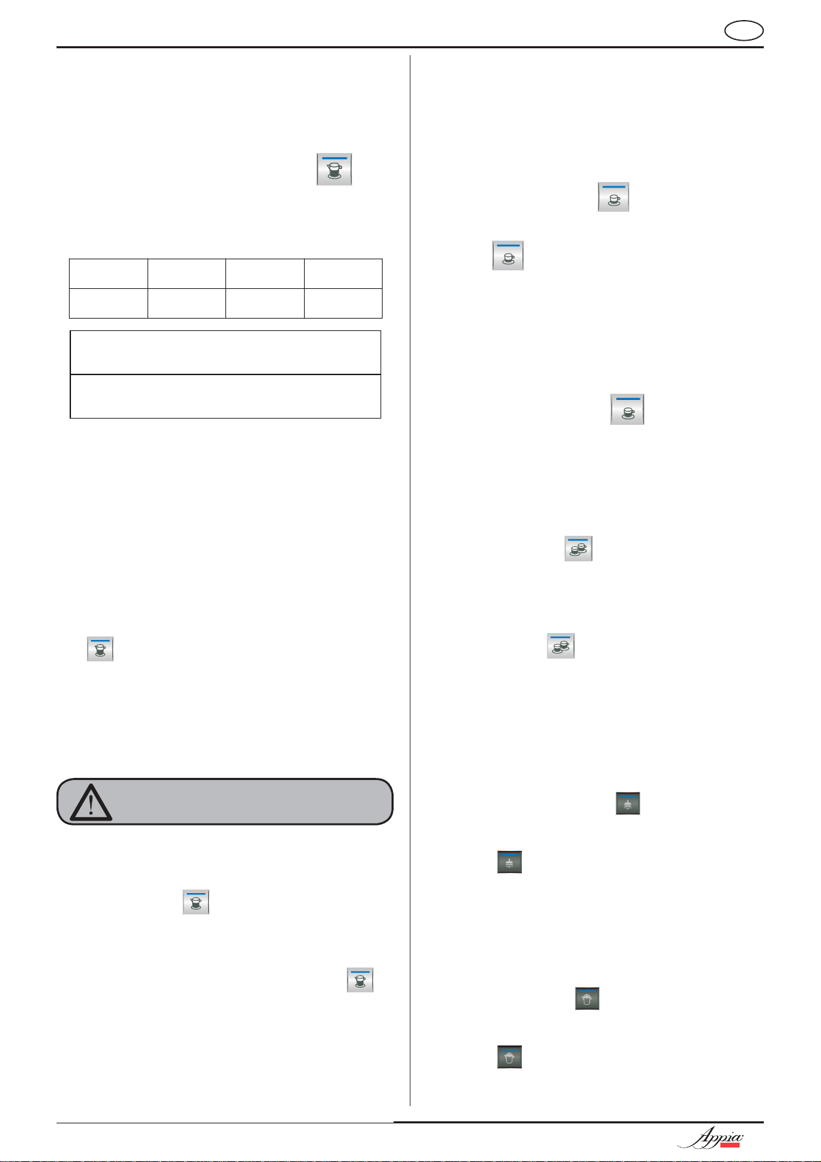
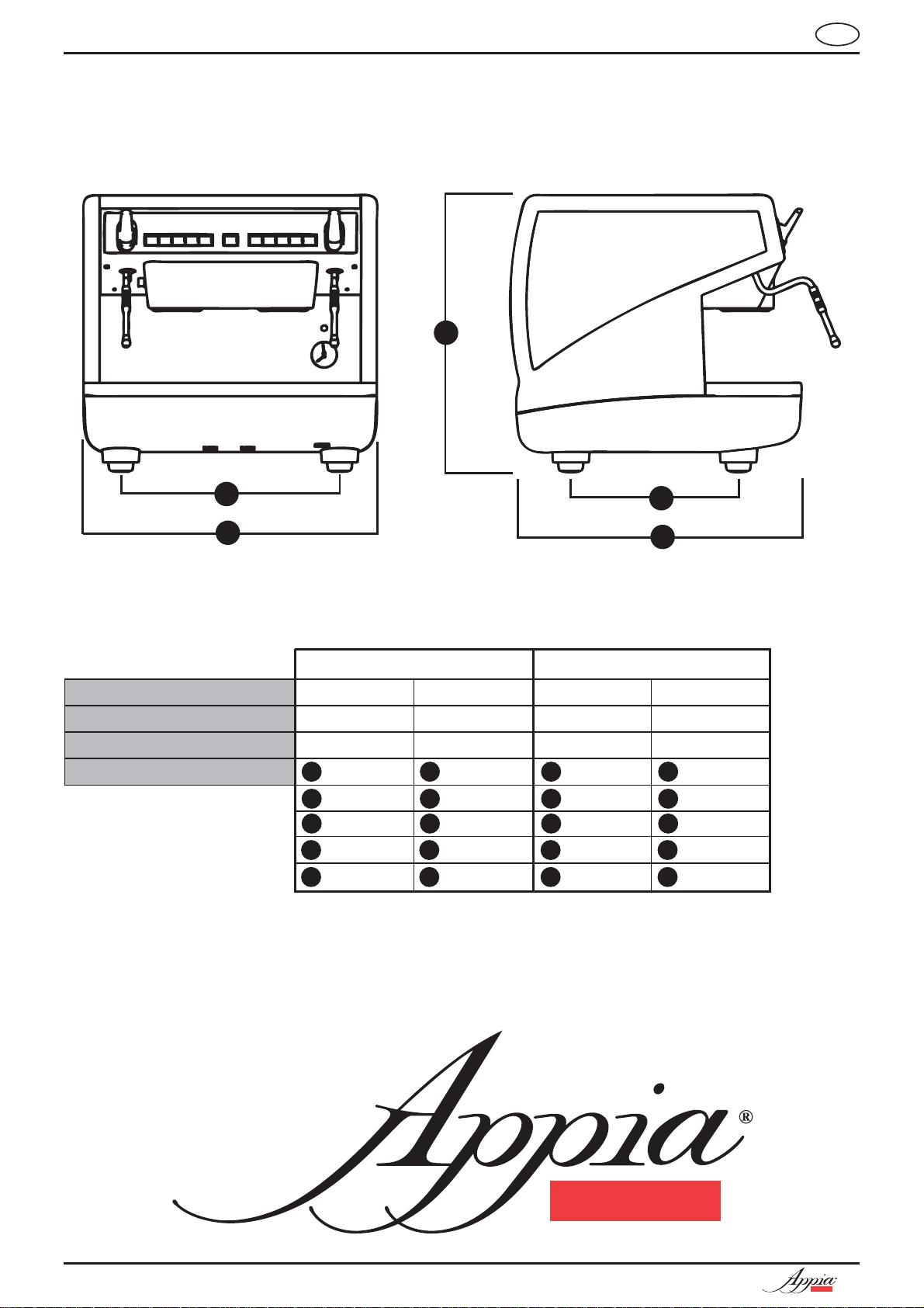
CARATTERISTICHE TECNICHE
E
IT
B
A
D
C
220 V 110 V
PESO NETTO
60 kg 133 lb 60 kg 133 lb
PESO LORDO 65 kg 143 lb 65 kg 143 lb
POT. TERMICA 2600 W 2600 W 1500/2200 W 1500/2200 W
DIMENSIONI 550 mm 21.6 550 mm 21.6
A
B
460 mm 18 460 mm 18
C
545 mm 21.4 545 mm 21.4
D
370 mm 14.5 370 mm 14.5
E
530 mm 20.8 530 mm 20.8
A
B
C
D
E
A
B
C
D
E
A
B
C
D
E
2
COMPACT
COMPACT
Page 5

IT
INDICE
CARATTERISTICHE TECNICHE....
1. DESCRIZIONE...............................4
1.1 DESCRIZIONE TASTIERE ..................................5
1.1 LISTA ACCESSORI ............................................6
2. PRESCRIZIONI DI SICUREZZA.....7
3. TRASPORTO E
MOVIMENTAZIONE.....................10
3.1 IDENTIFICAZIONE MACCHINA .....................10
3.2 TRASPORTO ..................................................10
3.3 MOVIMENTAZIONE........................................10
4. INSTALLAZIONE E OPERAZIONI
PRELIMINARI..............................11
5. REGOLAZIONI DEL
TECNICO QUALIFICATO .............13
5.1 RIEMPIMENTO MANUALE CALDAIA ............13
5.2 REGOLAZIONE PRESSIONE CALDAIA .........13
5.3 REGOLAZIONE PRESSIONE POMPA .............14
5.4 REGOLAZIONE ECONOMIZZATORE
ACQUA CALDA ............................................. 15
2
8. PULIZIA E MANUTENZIONE ......22
8.1 PULIZIA DELLA CARROZZERIA ....................22
8.2 PULIZIA DELLE DOCCETTE INOX.................22
8.3 PULIZIA DEL GRUPPO CON
L'AUSILIO DEL FILTRO CECO ...................... 22
8.4 PULIZIA DEI FILTRI E PORTAFILTRI ...........23
8.5 RIGENERAZIONE RESINE ADDOLCITORE.... 23
11. MESSAGGI ERRORI
MACCHINA..................................24
6. UTILIZZO ...................................16
6.1 ACCENSIONE ................................................16
6.2 SPEGNIMENTO.............................................. 16
6.3 PREPARAZIONE CAFFE’................................ 16
6.4 UTILIZZO DEL VAPORE ...............................17
6.5 PREPARAZIONE DEL CAPPUCCINO .............17
6.6 SELEZIONE ACQUA CALDA ..........................17
6.7 SELEZIONE VAPORE TEMPORIZZATO .........17
6.8 SELEZIONE VAPORE AUTOSTEAM...............17
7. PROGRAMMAZIONE ....................19
7.1 PROGRAMMAZIONE DOSI............................. 19
7.2 PROGRAMMAZIONE DOSI CAFFÈ................. 19
7.3 PROGRAMMAZIONE
VAPORE TEMPORIZZATO .............................19
7.4 PROGRAMMAZIONE AUTOSTEAM ................19
7.5 PROGRAMMAZIONE ACQUA CALDA.............19
7.6 PROGRAMMAZIONE DOSI STANDARD .........20
7.7 COPIATURA DOSI..........................................20
7.8 PROGRAMMAZIONE
PARAMETRI DI FUNZIONAMENTO................20
7.9 CICLO AUTOMATICO DI PULIZIA GRUPPI....21
COMPACT
3
Page 6
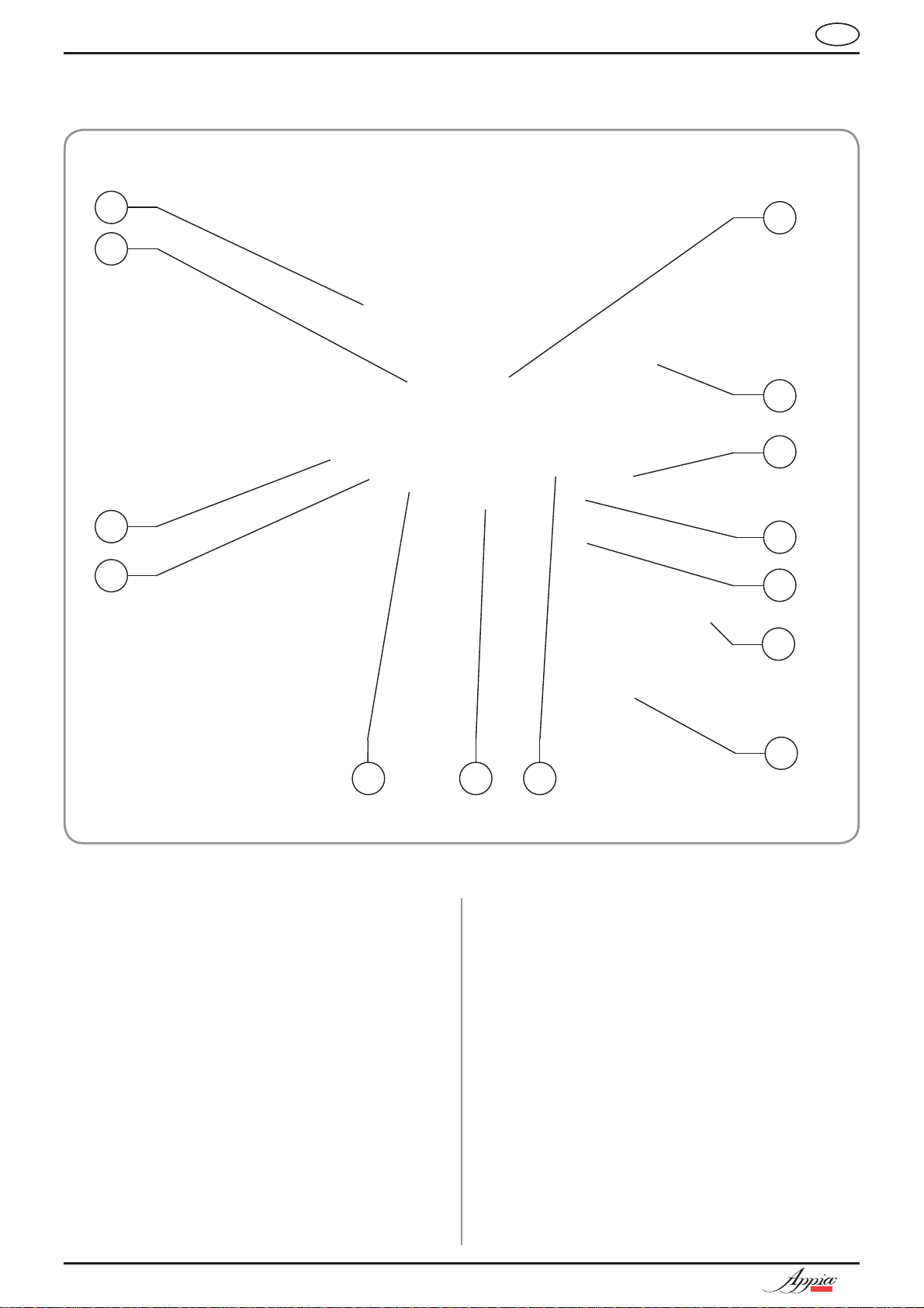
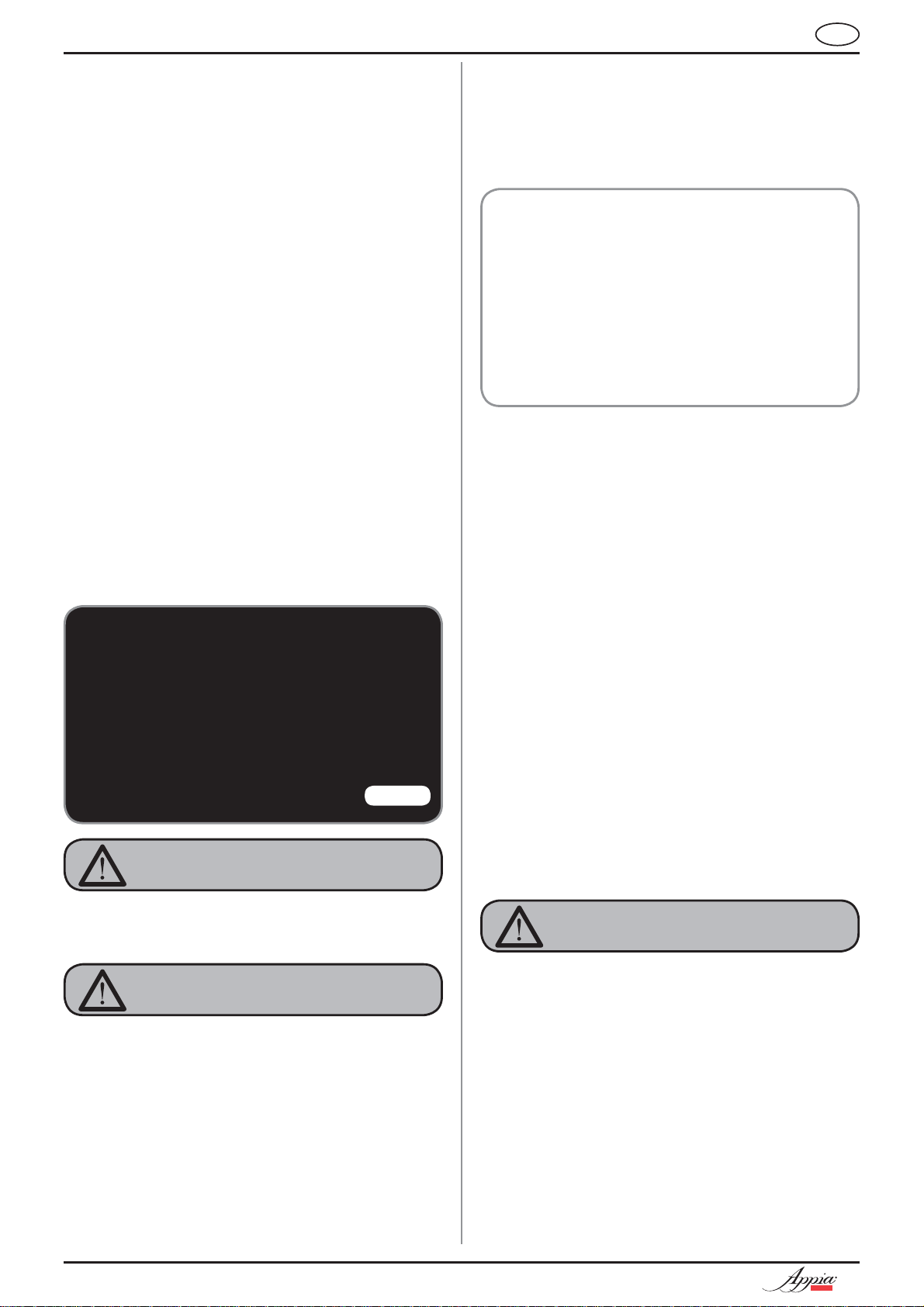
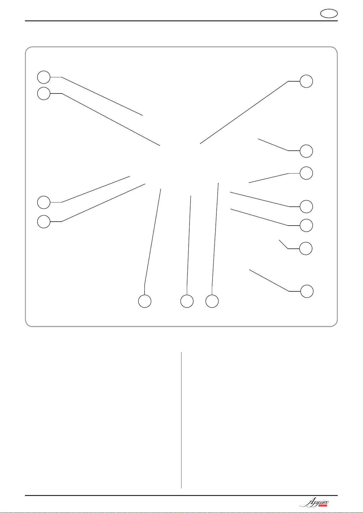
1. DESCRIZIONE
IT
14
2
12
4
1
3
5
8
9
13
LEGENDA
1 Pulsanti selezione
2 Pulsanti erogazione
3 Manopola vapore
4 Lancia vapore
5 Portafiltro
6 Becco 1 caffè
7 Becco 2 caffè
8 Livello ottico
9 Manometro
10 Piede regolabile
7 6
11
11 Lancia Acqua calda
12 Targhetta dati
13 Interruttore generale
14 Scaldatazze (optional)
10
Fig. 1
4
COMPACT
Page 7
IT
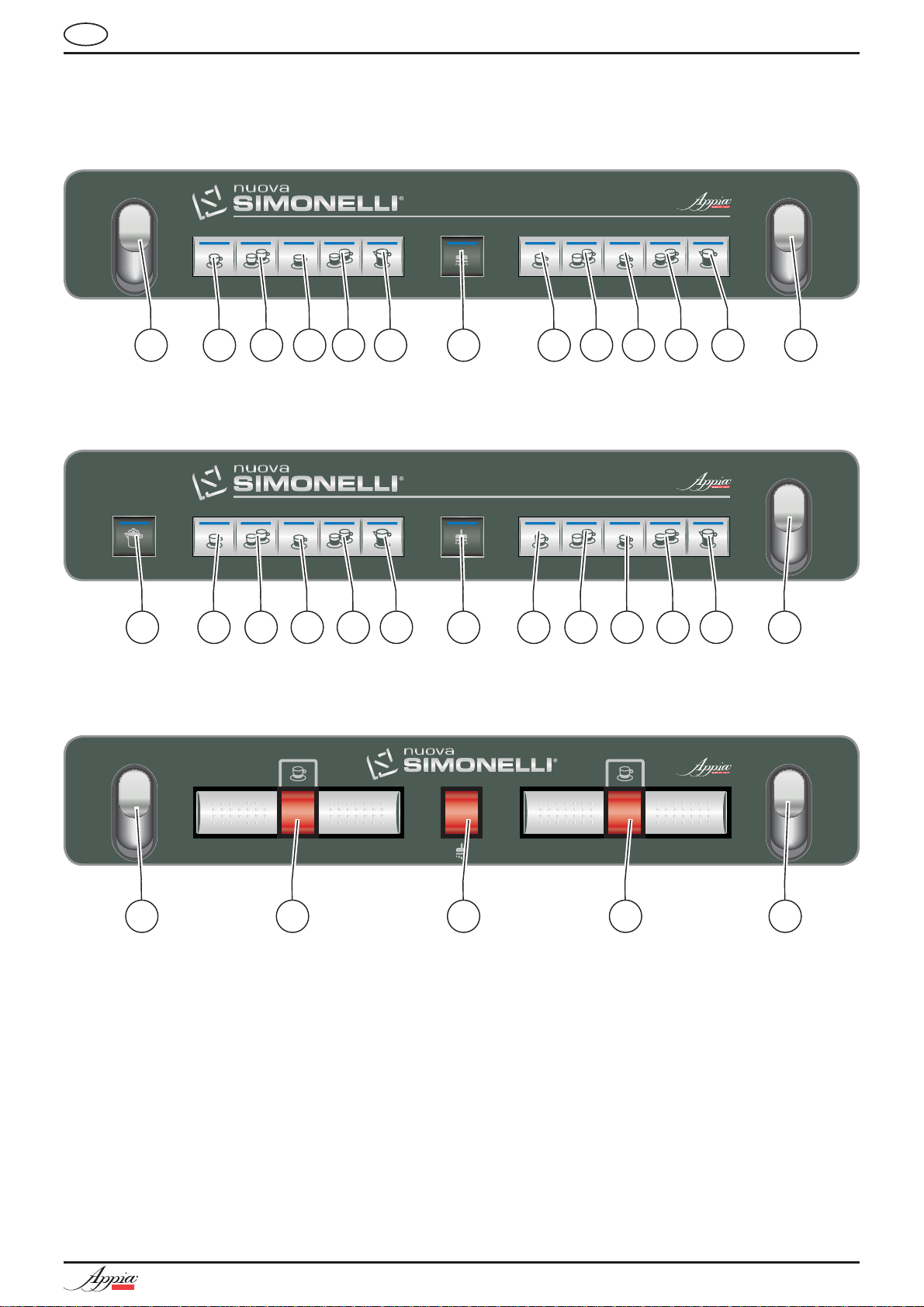
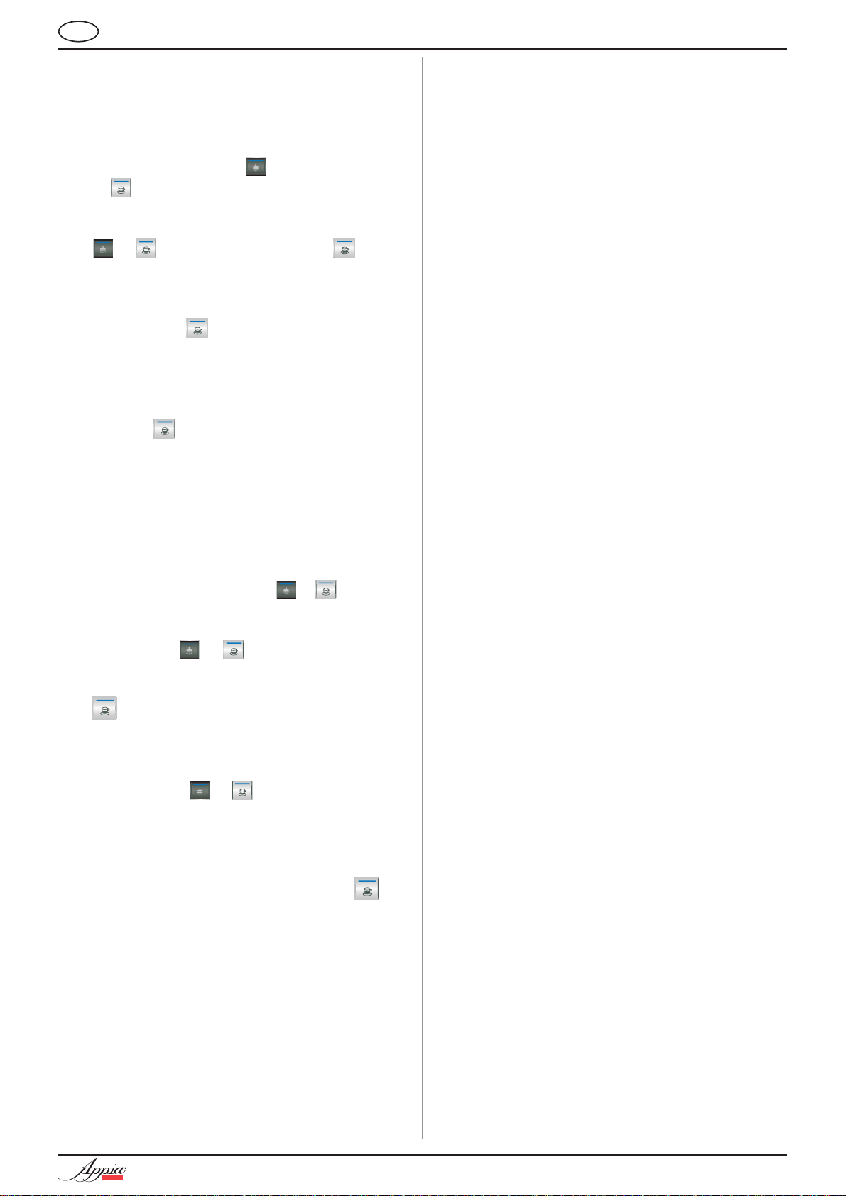
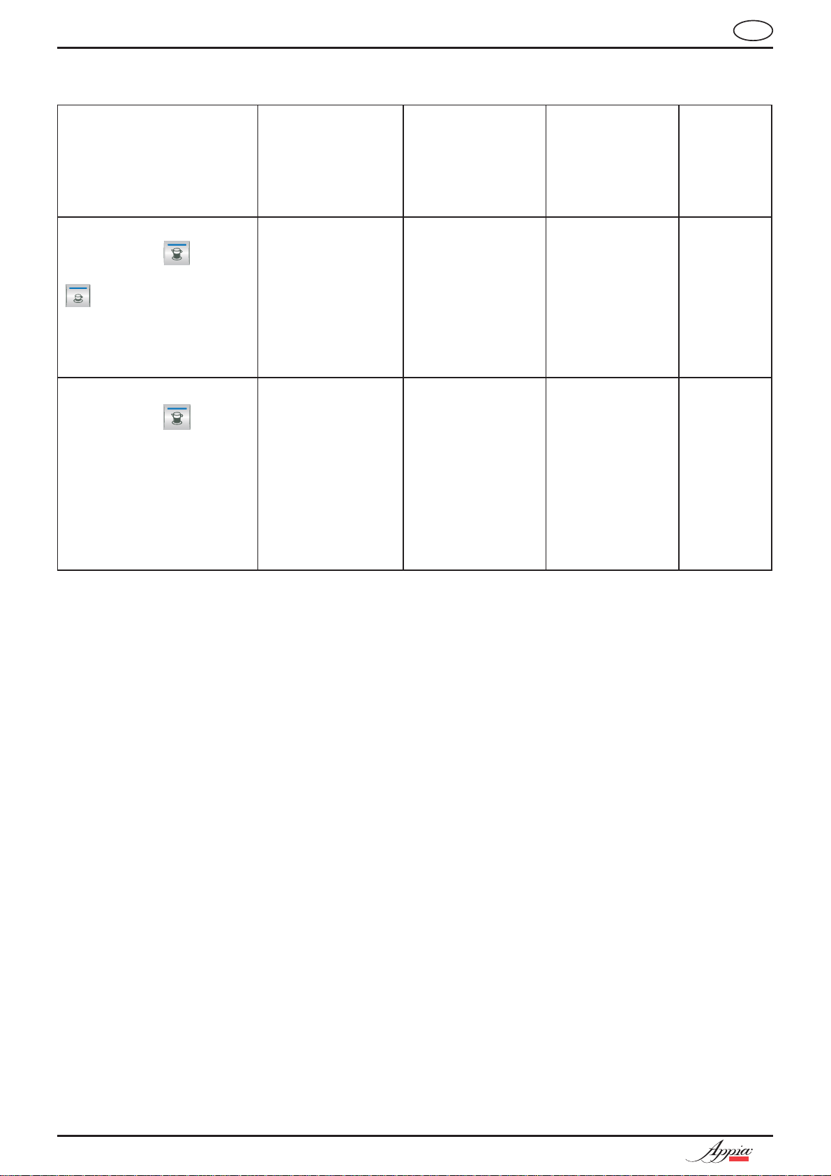
1.1 DESCRIZIONE TASTIERE
APPIA COMPACT VOLUMETRICA
1
2 3 4 5 6 7 1 2 3 4 5 7
APPIA COMPACT VOLUMETRICA AUTOSTEAM
8 7
1
2 3 4 5 6 1
APPIA COMPACT SEMIAUTOMATICA
2 3 4 5
9 7 6 9 7
LEGENDA
Tasto 1 Espresso
1
2
Tasto 2 Espressi
3
Tasto 1 Caffè
4
Tasto 2 Caffè
5 Tasto caffè continuo
6
Tasto Acqua Calda
7 Tasto Vapore
8 Tasto autosteam / vapore temporizzato
9
Tasto Caffè
COMPACT
5
Page 8
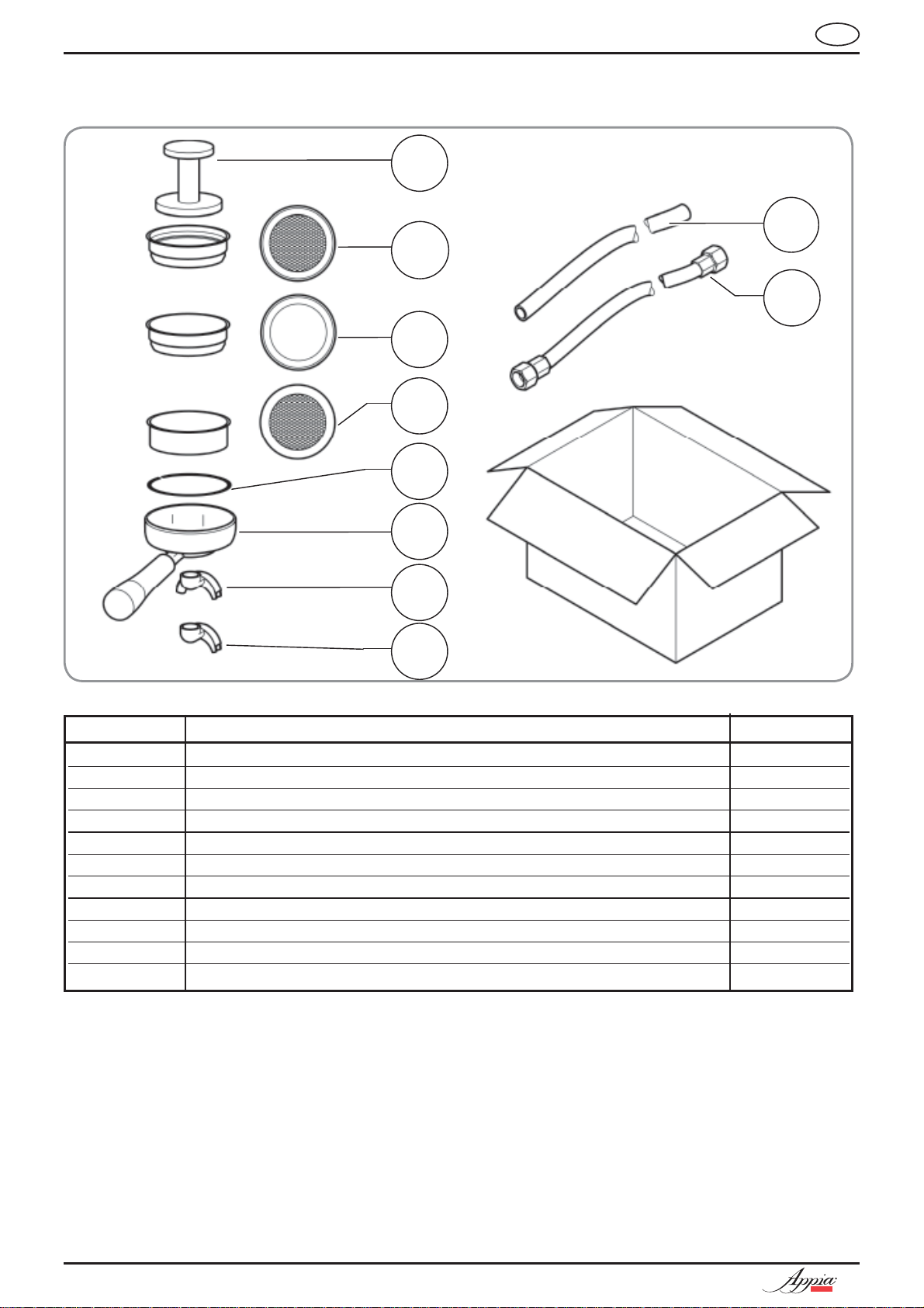
1.2 LISTA ACCESSORI
IT
A10
A02
A05
A01
A06
A04
A07
A03
A08
A09
Fig. 2
CODICE DESCRIZIONE QUANTITÀ
A01 Tubo carico C\,” 1
A02 Tubo scarico Ø 25 mm - L. 150 cm 1
A03 Portafiltro 3
A04 Filtro doppio 2
A05 Filtro singolo 1
A06 Filtro cieco 1
A07 Molla 3
A08 Becco erogazione doppio 2
A09 Becco erogazione singolo 1
A10 Pressa caffè 1
A11 Griglie plastica 3
6
COMPACT
Page 9
IT
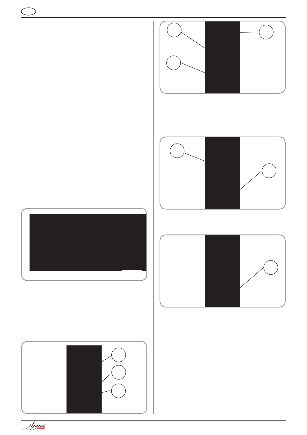
2. PRESCRIZIONI DI SICUREZZA
Il presente libretto costituisce parte
integrante ed essenziale del prodotto e
dovrà essere consegnato all’utilizzatore.
Leggere attentamente le avvertenze contenute nel presente libretto in quanto forniscono importanti indicazioni riguardanti la
sicurezza di installazione, d’uso e manutenzione. Conservare con cura questo
libretto per ogni ulteriore consultazione.
Dopo aver tolto l’imballaggio assicurarsi
dell’integrità dell’apparecchio. In caso di
dubbio non utilizzare l’apparecchio e rivolgersi a personale professionalmente qualificato. Gli elementi dell’imballaggio (sacchetti
in plastica, polistirolo espanso, chiodi, ecc.)
non devono essere lasciati alla portata dei
bambini in quanto potenziali fonti di pericolo, né essere dispersi nell’ambiente.
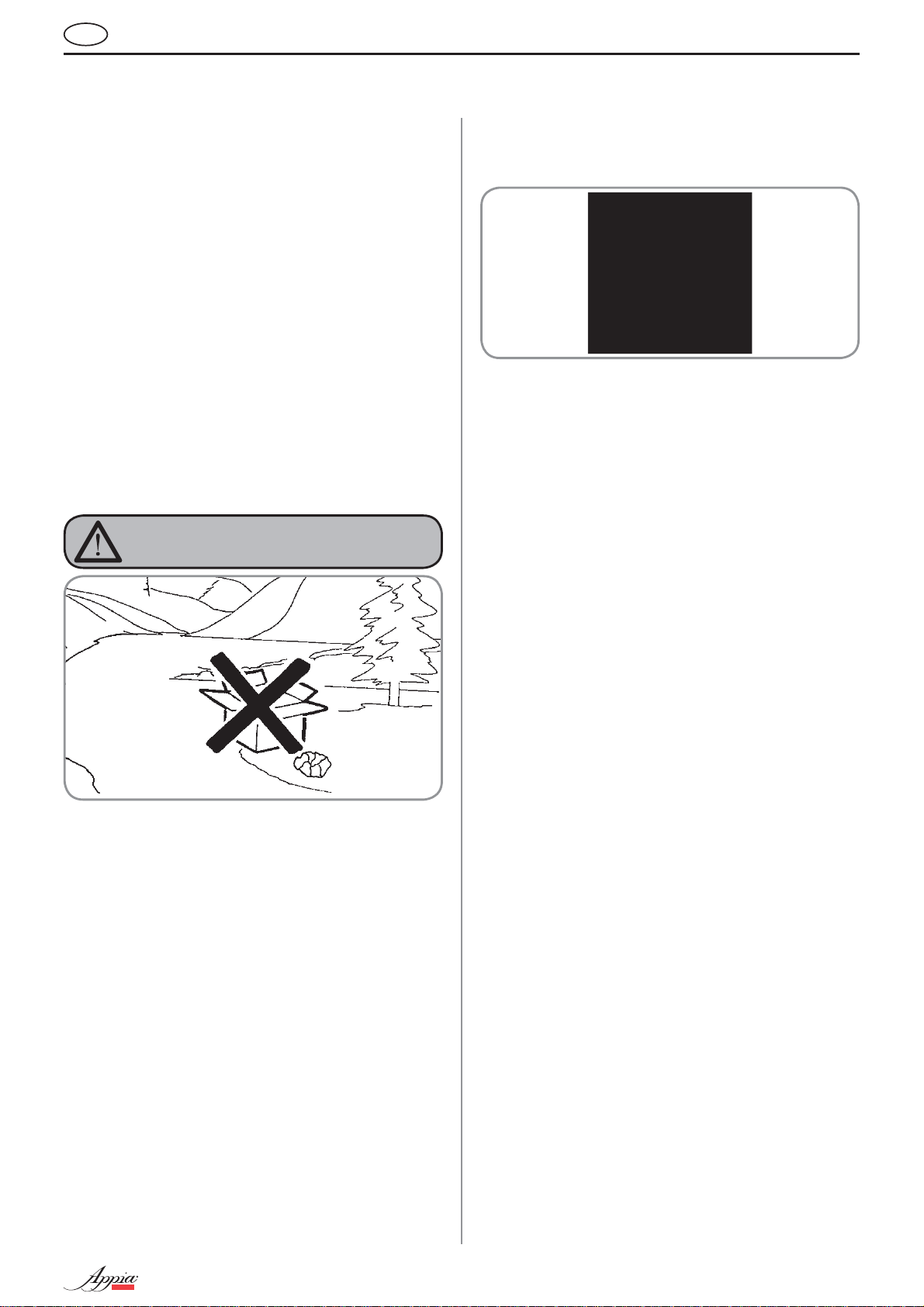
PERICOLO DI INQUINAMENTO
verificare che la portata elettrica dell’impianto sia adeguata alla potenza massima
dell’apparecchio indicata in targa.
Fig. 4
In particolare dovrà anche accertare che la
È vietato l’uso di adattatori, prese multiple
sezione dei cavi dell’impianto sia idonea
alla potenza assorbita dall’apparecchio.
e prolunghe. Qualora il loro uso si rendesse indispensabile è necessario chiamare
un elettricista munito di patentino.
Durante l'installazione del dispositivo
devono essere utilizzati i componenti
e i materiali in dotazione al dispositivo
stesso. Qualora fosse necessario l'utilizzo di altra componentistica, l'installatore
deve verificare l'idoneità dello stesso ad
essere utilizzato a contatto con l'acqua
per consumo umano.
Fig. 3
La macchina è adatta per essere installata
Il costruttore non può essere considerato
in ambienti quali locali di servizio per
il personale presso negozi, uffici e altri
ambienti di lavoro, in agriturismi, presso
gli spazi per clienti in hotels, motels, bed
and breakfast e altri ambiti residenziali.
Prima di collegare l’apparecchio accertarsi
che i dati di targa siano rispondenti a quelli
della rete di distribuzione elettrica. La targa
è situata sul frontale della macchina in alto
a destra. L’installazione deve essere effettuata in ottemperanza alle norme vigenti,
secondo le istruzioni del costruttore e da
personale qualificato.
responsabile per eventuali danni causati
dalla mancanza di messa a terra dell’impianto. Per la sicurezza elettrica di questo
apparecchio è obbligatorio predisporre l’impianto di messa a terra, rivolgendosi ad un
elettricista munito di patentino, che dovrà
La macchina deve essere installata nel
Per questa ragione, i collegamenti idrau-
rispetto delle normative comunitarie, statali e locali in vigore relative agli impianti
idraulici, compresi i dispositivi di prevenzione dei riflussi.
lici devono essere eseguiti da un tecnico
qualificato.
L'alimentazione del dispositivo deve
essere effettuata con acqua idonea al
consumo umano conforme alle disposizioni vigenti nel luogo di installazione.
L'installatore deve acquisire dal proprietario/gestore dell'impianto conferma che
l'acqua rispetti i requisiti sopra indicati.
Questo apparecchio dovrà essere desti-
nato solo all’uso descritto in questo
manuale. Il costruttore non può essere
considerato responsabile per eventuali
danni causati da usi impropri, erronei ed
irragionevoli.
L’apparecchio non è idoneo per l’utilizzo
da parte dei bambini, persone con ridotte
capacità fisiche, sensoriali o mentali, o
carenti di conoscenze a meno che non sia
data supervisione o istruzione.
COMPACT
7
Page 10
Al termine dell'installazione, il dispositivo
Successivamente il dispositivo viene
- 100% del circuito caffè attraverso l'ero-
- 100% del circuito acqua calda attraverso
- apertura di ciascuna uscita vapore per 1
Al termine dell'installazione sarebbe
viene attivato e portato fino alla condizione nominale di lavoro lasciandolo in
condizioni di “pronto al funzionamento”.
spento e tutto il circuito idraulico viene
svuotato della prima acqua immessa in
modo da eliminare eventuali impurità iniziali. In seguito il dispositivo viene nuovamente caricato e portato fino alle condizioni nominali di funzionamento. Dopo il
raggiungimento dello stato di “pronto al
funzionamento” si effettuano le seguenti
erogazioni:
gatore caffè (per più erogatori si divida in
uguale misura);
l'erogatore acqua (per più erogatori si
divida in uguale misura);
minuto
buona regola stilare un rapporto di quan-
to effettuato.
Le temperature massime e minime di
immagazzinamento devono essere comprese nel range [-5,+50]°C.
IT
Fig. 5
• non lasciare esposto l’apparecchio
ad agenti atmosferici (pioggia, sole,
ecc.);
• non permettere che l’apparecchio sia
usato da bambini, o da personale non
autorizzato e che non abbia letto e ben
compreso questo manuale.
Il tecnico autorizzato deve, prima di effet-
tuare qualsiasi operazione di manutenzione, staccare la spina e spegnere l’interruttore della macchina.
La temperatura di funzionamento deve
Il cavo di alimentazione deve essere sostituito
da un Tecnico Specializzato con un Ricambio
Originale, disponibile presso i Centri di
Assistenza Autorizzati, provvisto di un conduttore di terra speciale
In particolare:
• non toccare l’apparecchio con mani o
• non usare l’apparecchio a piedi nudi;
• non usare, prolunghe in locali adibiti a
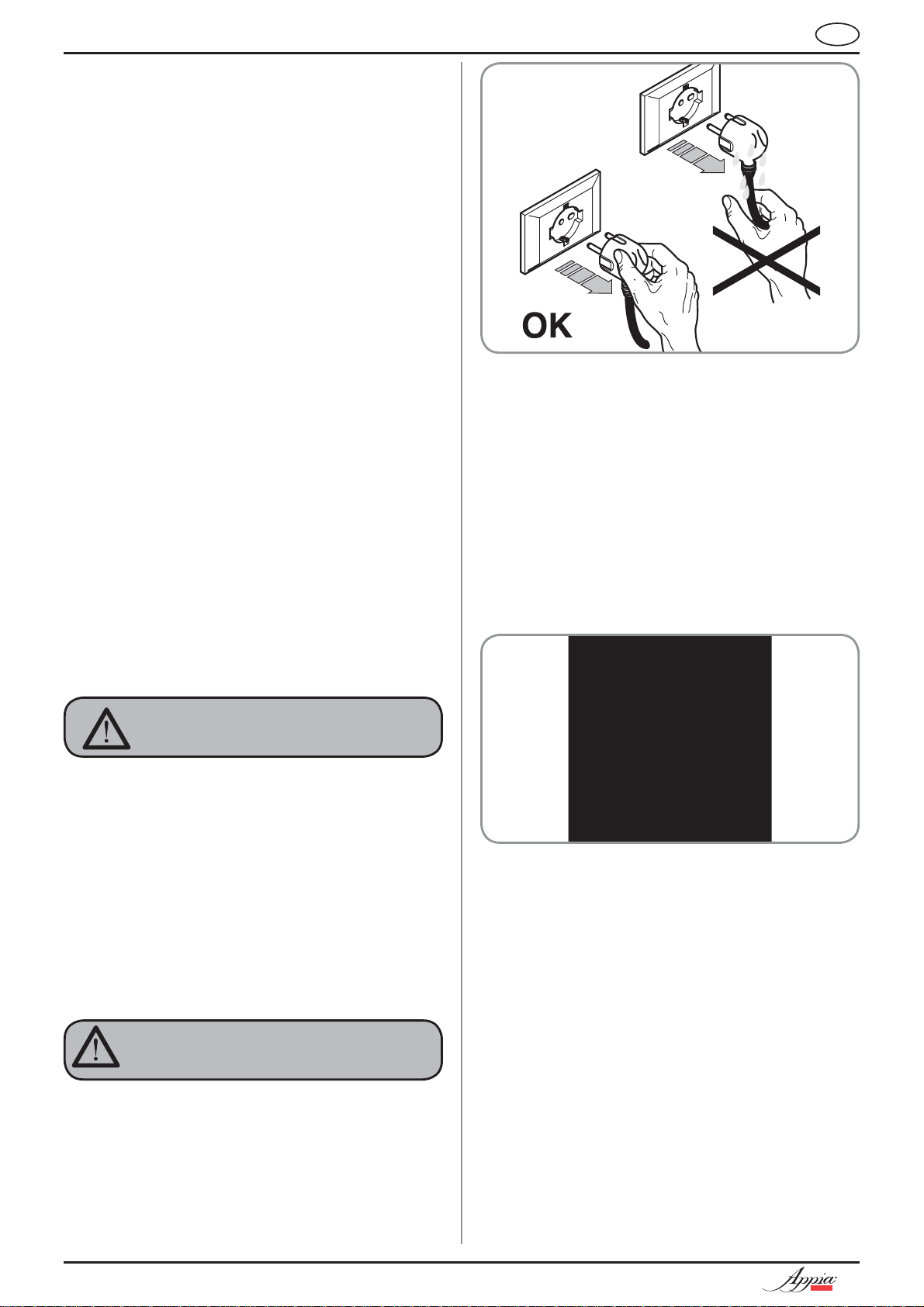
• non tirare il cavo di alimentazione, per
essere compresa nel range [+5, +35]°C.
ATTENZIONE
L’uso di un qualsiasi apparecchio elet-
trico comporta l’osservanza di alcune
regole fondamentali.
piedi bagnati;
ATTENZIONE
PERICOLO DI SCOSSA ELETTRICA
bagno o doccia;
scollegare l'apparecchio dalla rete di
alimentazione;
Fig. 6
Per le operazioni di pulizia portare la macchina
L’eventuale riparazione dei prodotti dovrà
Il mancato rispetto di quanto sopra può com-
a stato energetico “O”, cioè “INTERRUTTORE
MACCHINA SPENTO E SPINA ST ACCAT A” ed
attenersi esclusivamente a quanto previsto
nel presente libretto.
In caso di guasto o di cattivo funzionamento
dell’apparecchio, spegnerlo. È severamente
vietato intervenire. Rivolgersi esclusivamente a personale professionalmente qualificato.
essere effettuata solamente dalla casa
costruttrice o da centro di assistenza autorizzato utilizzando esclusivamente ricambi
originali.
promettere la sicurezza dell’apparecchio.
8
COMPACT
Page 11
IT
All’installazione, l’elettricista munito di
patentino dovrà prevedere un interruttore
onnipolare come previsto dalle normative
di sicurezza vigenti con distanza di apertura dei contratti uguale o superiore a 3 mm.
Per evitare surriscaldamenti pericolosi si
raccomanda di svolgere per tutta la sua
lunghezza il cavo di alimentazione.
Fig. 8
Non ostruire le griglie di aspirazione e/o di
dissipazione in particolare dello scaldatazze.
Il cavo di alimentazione di questo appa-
recchio non deve essere sostituito
dall’utente. In caso di danneggiamento, spegnere l’apparecchio e per la sua
sostituzione rivolgersi esclusivamente a
personale professionalmente qualificato.
Allorché si decida di non utilizzare più
un apparecchio di questo tipo si raccomanda di renderlo inoperante dopo
aver staccato la spina, tagliare il cavo di
alimentazione.
ATTENZIONE
PERICOLO DI INQUINAMENTO
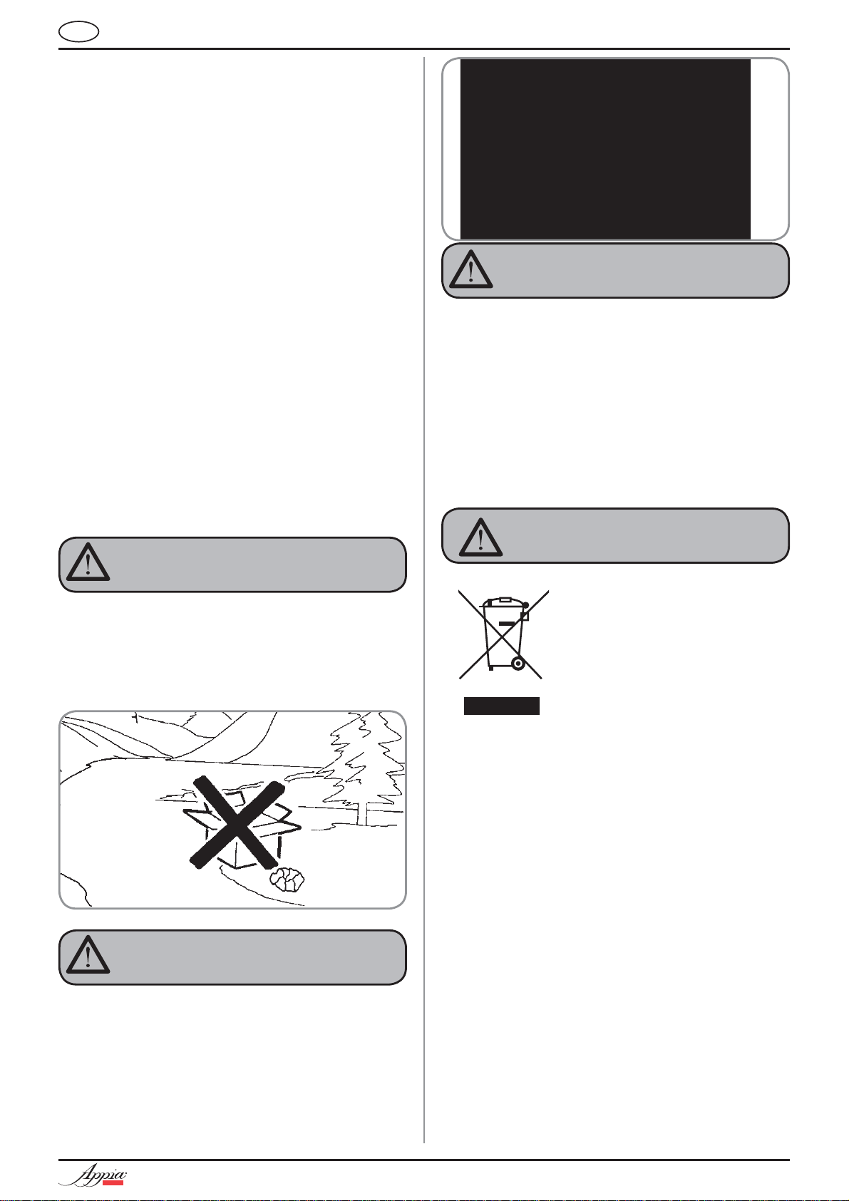
Non disperdere la macchina nell’ambien-
te: per lo smaltimento rivolgersi ad un
centro autorizzato o contattare il costruttore che darà indicazioni in merito.
Fig. 7
ATTENZIONE
PERICOLO DI USTIONE
Durante l’uso della lancia del vapore, pre-
stare molta attenzione e non mettere le
mani sotto di esso e non toccarla subito
dopo l’uso.
ATTENZIONE
PERICOLO DI USTIONE
Ricordare che prima di effettuare qualsia-
Il simbolo del cassonetto barrato riportato sull’apparecchiatura indica che il prodotto alla fine della
propria vita utile deve essere raccolto separatamente dagli altri rifiuti. L’ utente dovrà, pertanto,
conferire l’ apparecchiatura giunta a fine vita agli
idonei centri di raccolta differenziata dei rifiuti elettronici ed elettrotecnici, oppure riconsegnarla al
rivenditore al momento dell’acquisto di una nuova
apparecchiatura di tipo equivalente, in ragione di
uno a uno. L’ adeguata raccolta differenziata per
l’ avvio successivo dell’ apparecchiatura dimessa al riciclaggio,al trattamento e allo smaltimento
ambientalmente compatibile contribuisce ad evitare
possibili effetti negativi sull’ ambiente e sulla salute
e favorisce il riciclo dei materiali di cui è composta l’
apparecchiatura. Lo smaltimento abusivo del prodotto da parte dell’ utente comporta l’ applicazione delle
sanzioni amministrative di cui al D.Lgs.n.22/1997”
(articolo 50 e seguenti del D.Lgs.n.22/1997).
si operazione di installazione, manutenzione, scarico, regolazione, l’operatore
qualificato deve indossare i guanti da
lavoro e le scarpe antinfortunistiche.
Il massimo livello di disturbo sonoro
emesso è inferiore ai 70db.
Il tubo alla connessione idrica se sostitui-
to non deve essere più riutilizzato.
ATTENZIONE
INFORMAZIONE AGLI UTENTI
Ai sensi dell’ art. 13 del Decreto
Legislativo 25 luglio 2005, n.
151 “Attuazione delle Direttive
2002/95/CE, 2002/96/CE e
2003/108/CE, relative alla riduzione dell’ uso di sostanze pericolose nelle apparecchiature elettriche ed elettroniche, nonché allo
smaltimento dei rifiuti”.
COMPACT
9
Page 12
IT
3. TRASPORTO E
MOVIMENTAZIONE
3.1 IDENTIFICAZIONE
MACCHINA
Per qualsiasi comunicazione con il costruttore
Nuova Simonelli, citare sempre il numero di matricola della macchina.
Fig. 9
3.2 TRASPORTO
La macchina viene trasportata in pallett con più
macchine dentro scatoloni assicurati al pallett con
delle centine.
Prima di procedere a qualsiasi operazione di trasporto o movimentazione, l’operatore deve:
• indossare guanti e scarpe antinfortunistici ed una
tuta con elastici alle estremità.
Il trasporto del pallett deve essere ef fettuato con un
mezzo di sollevamento adeguato (tipo muletto).
3.3 MOVIMENTAZIONE
ATTENZIONE
PERICOLO DI URTO
O SCHIACCIAMENTO
L’operatore durante tutta la movimentazione,
deve avere l’attenzione che non ci siano persone, cose od oggetti nell’area di operazione.
Sollevare lentamente il pallett a circa 30 cm (11,8
in) da terra e raggiungere la zona di carico. Dopo
aver verificato che non ci siano ostacoli, cose o
persone, procedere al carico.
Una volta arrivati a destinazione, sempre con un
mezzo di sollevamento adeguato (es. muletto),
dopo essersi assicurati che non ci siano cose
o persone nell’area di scarico, portare il pallett
a terra e movimentarlo a circa 30 cm (11,8 in) da
terra, fino all’area di immagazzinamento.
ATTENZIONE
PERICOLO DI URTO
O SCHIACCIAMENTO
Prima della seguente operazione verificare che il
carico sia a posto e che con il taglio delle centine
non cada.
L’operatore con guanti e scarpe antinfortunistiche, deve procedere al taglio delle centine e allo
stoccaggio del prodotto, in questa operazione
consultare le caratteristiche tecniche del prodotto per vedere il peso della macchina da immagazzinare e potersi regolare di conseguenza.
ATTENZIONE
PERICOLO DI INQUINAMENTO
Fig. 10
10
COMPACT
Page 13
IT
4. INSTALLAZIONE
E OPERAZIONI
PRELIMINARI
Prima di procedere a qualsiasi operazione di
installazione e regolazione, devono essere lette e
ben comprese le PRESCRIZIONI DI SICUREZZA di
questo manuale. L'azienda non risponde di alcun
danno a cose o a persone derivante da una mancata osservanza delle prescrizioni di sicurezza,
installazione e manu tenzione, di questo manuale.
ATTENZIONE
PERICOLO DI INQUINAMENTO
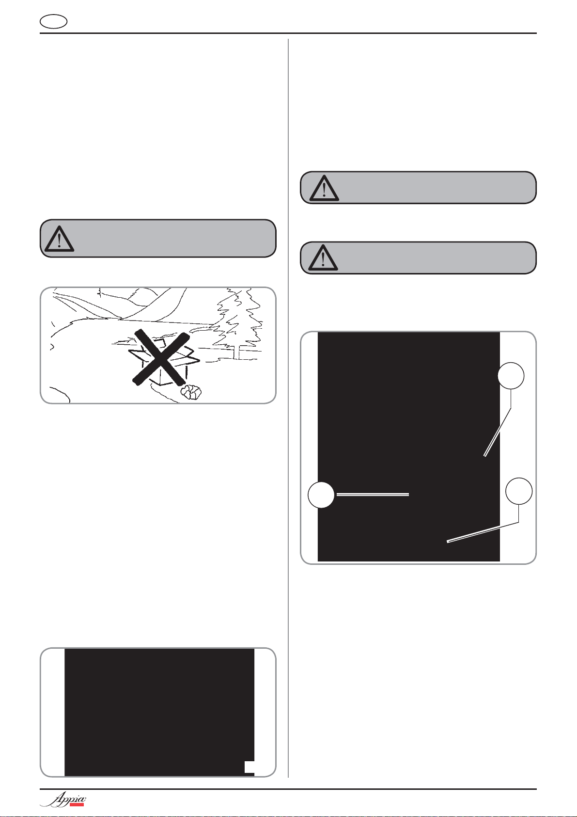
Non disperdere l’imballo nell’ambiente.
In fase preliminare, dopo la messa in piano della
macchina, si consiglia di installare un addolcitore
(1), all’uscita della rete idrica, e di seguito un filtro a
maglia (2). Questo non permette alle impurità, come
sabbia, particelle di calcare in sospensione, ruggine
ecc., di danneggiare le delicate superfici in grafite,
garantendo una buona durata della macchina.
Dopo queste operazioni, provvedere ai collegamenti
idraulici come illustrato nella seguente figura.
ATTENZIONE
La pressione della rete idrica raccomandata è [2,3]
bar.
ATTENZIONE
Evitare strozzature nei tubi di collegamento.
Verificare inoltre che lo scarico (3) sia in grado di
eliminare gli scarti.
Fig. 11
Una volta rimosso l’imballo e aver verificato l’integrità della macchina e degli accessori, procedere come
descritto di seguito:
• posizionare la macchina su un piano orizzontale;
• assemblare i piedini di sostegno della macchina
inserendo l’inserto all’interno del guscio cilindrico;
• avvitare il piedino in gomma nella filettatura dell’inserto contenuto nel guscio;
• avvitare tutto il gruppo assemblato nelle apposite
sedi di alloggiamento dei piedini della macchina;
• mettere in piano la macchina agendo sui piedini di
regolazione;
NOTA: la scanalatura del guscio deve essere
rivolta verso l’alto, come indicato nella
figura successiva.
2
1
3
Fig. 13
LEGENDA
1 Addolcitore
2 Filtro a maglia
3 Scarico Ø 50 mm
NOTA: Per un buon funzionamento della macchi-
na occorre che la pressione di rete non
superi i 4 bar.
In caso contrario, installare un riduttore di
pressione a monte dell’addolcitore; il tubo
in entrata dell’acqua deve avere un diametro interno non inferiore ai 6 mm.
COMPACT
Fig. 12
11
Page 14
ATTENZIONE
PERICOLO DI SCOSSA ELETTRICA
La macchina deve essere sempre protetta con un
interruttore automatico onnipolare di adeguata
potenza con distanza di apertura dei contatti
uguale o superiore a 3 mm.
La Nuova Simonelli non risponde di alcun danno
a cose o persone derivante dalla mancata osservanza delle vigenti norme di sicurezza.
Prima di allacciare la macchina a una rete elettrica
verificare che il voltaggio indicato sulla targhetta dati
della macchina corrisponda a quello della rete.
NOTA: All'inizio della attività giornaliera e comun-
que nel caso in cui vi siano pause maggiori
di 8 ore bisogna procedere ad effettuare il
ricambio del 100% dell'acqua contenuta nei
circuiti utilizzando gli erogatori preposti.
IT
NOTA: In caso di esercizi in cui il servizio è conti-
nuativo effettuare i ricambi di sopra descritti
almeno con frequenza settimanale.
12
COMPACT
Page 15
IT
5. REGOLAZIONI
DEL TECNICO
QUALIFICATO
ATTENZIONE
Le regolazioni di seguito elencate devono essere
eseguite SOLO dal Tecnico Specializzato.
La Nuova Simonelli non risponde di alcun danno
a cose o persone, derivanti da una mancata osservanza delle prescrizioni di sicurezza,
descritte in questo manuale.
ATTENZIONE
PERICOLO DI SCOSSA ELETTRICA
Il tecnico specializzato deve, prima di effetture
qualsiasi operazione di regolazione, spegnere
l'interruttore della macchina e staccare la spina.
• agire sul rubinetto livello manuale, per permettere l’ingrasso dell’acqua nella caldaia, per circa
20/30 sec.;
1
Fig. 15
2
5.1 RIEMPIMENTO
MANUALE CALDAIA
Tutti i modelli sono muniti di sonda di
livello, per mantenere costante il livello di acqua
all’interno della caldaia.
E’ buona norma, al primo avviamento della macchina, riempire manualmente la caldaia per evitare che
la resistenza elettrica si danneggi e che inserisca la
protezione elettronica.
Se questo dovesse accadere, è sufficiente spegnere la macchina e riaccenderla, per completarne il
caricamento (vedi capitolo “MESSAGGI FUNZIONE
MACCHINA - ERRORE LIVELLO”).
Per effettuare il primo riempimento manuale, agire
come descritto di seguito:
• rimuovere la griglia del piano di lavoro;
• togliere la protezione in lamiera svitando le quattro viti laterali (A) come illustrato nella seguente
figura.
Fig. 16
1: Posizione di lavoro
2: Posizione di carico manuale
Al termine delle regolazioni, riposizionare la protezione in lamiera nell’apposito alloggiamento e
fissarla con le quattro viti laterali; riposizionare la
griglia del piano di lavoro.
5.2
REGOLAZIONE
PRESSIONE CALDAIA
(Regolazione pressostato)
Per modificare la pressione di esercizio della caldaia,
quindi la temperatura dell’acqua, in funzione delle varie
esigenze o delle caratteristiche del caffè utilizzato,
agire come descritto di seguito:
• svitare le 4 viti del pannello superiore (Fig. 17);
A
COMPACT
Fig. 14
Fig. 17
13
Page 16
IT
• agire sulla vite di regolazione del pressostato per
AUMENTARE (senso orario) oppure DIMINUIRE
(senso antiorario) la pressione;
Fig. 18
Valore consigliato: 1 - 1,4 bar
(secondo il tipo di caffè).
5.3 REGOLAZIONE
PRESSIONE POMPA
Per regolare la pressione della pompa, agire come
descritto di seguito:
• rimuovere la griglia del piano di lavoro;
• togliere la protezione in lamiera svitando le quattro viti laterali (A) come illustrato nella seguente
figura;
• La pressione impostata della pompa viene visualizzata nel settore inferiore del manometro nel
momento dell'erogazione del caffè
Fig. 21
Al termine delle regolazioni, riposizionare la protezione in lamiera nell’apposito alloggiamento e fissarla
con le quattro viti laterali; riposizionare la griglia del
piano di lavoro.
A
Fig. 19
• Agire sulla vite di regolazione della pompaper
AUMENTARE (senso orario) oppure DIMINUIRE
(senso antiorario) la pressione;
Fig. 20
Valore consigliato: 9 bar
14
COMPACT
Page 17
IT
5.4 REGOLAZIONE
ECONOMIZZA T ORE
ACQUA CALD A
Tutti i modelli sono equipaggiati di un
miscelatore di acqua calda, il quale permette di
regolare la temperatura di uscita dell’acqua e di
ottimizzare il rendimento del sistema.
Per regolare l’economizzatore acqua calda, occorre
rimuovere il pannello superiore della macchina,
operando come descritto di seguito:
• svitare le 4 viti del pannello superiore (Fig. 22);
Fig. 22
• per regolare la temperatura dell'acqua calda in
uscita dalla lancia, ruotare il pomello di registro in
senso ORARIO / ANTIORARIO per AUMENT ARE
/ DIMINUIRE la temperatura;
Fig. 23
• al termine dell'operazione rimontare il pannello
superiore della macchina.
COMPACT
15
Page 18
IT
6. UTILIZZO
L’operatore deve prima di iniziare la lavorazione,
accertarsi di aver letto e ben compreso le prescrizioni di sicurezza di questo manuale.
6.1 ACCENSIONE
• Collegare la macchina alla presa elettrica.
• Posizionare l'interruttore generale (n.13, Fig 1) in
posizione “I”.
Fig. 24
6.2 SPEGNIMENTO
6.3 PREPARAZIONE DEL
CAFFE
Sganciare il portafiltro e riempire di una o due dosi di
caffè macinato a seconda del filtro utilizzato.
Fig. 25
Pressare il caffè con l’apposito pressino in dotazione, pulire dai residui di polvere di caffè il bordo
anulare del filtro (per garantire una migliore tenuta e
un’inferiore usura della guarnizione).
Innestare quindi il portafiltro nel gruppo.
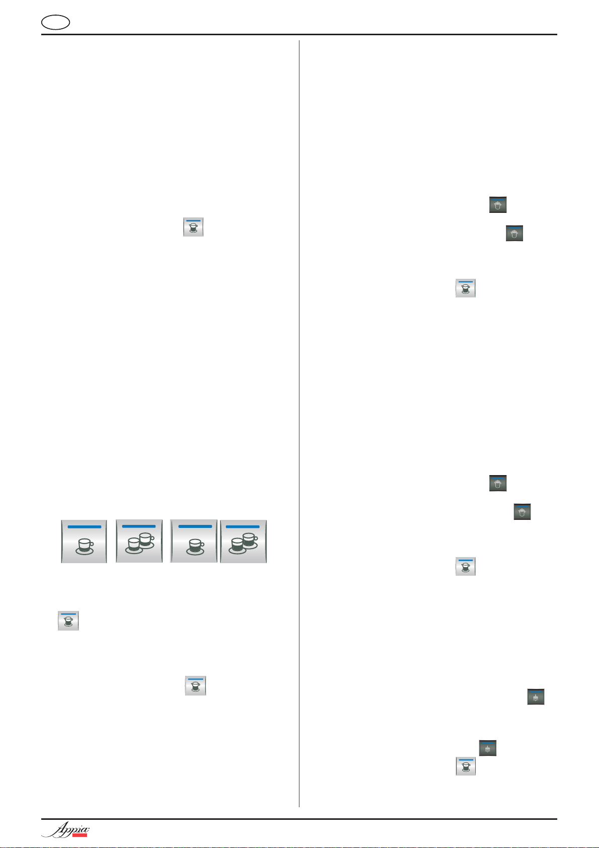
Premere il pulsante caffè desiderato:
• Posizionare l'interruttore generale (n. 13, Fig 1) in
posizione “O”.
• Scollegare la macchina alla presa elettrica.
1 Caffè corto
1 Caffè lungo
2 Caffè corto
2 Caffè lungo
Si attiva la pompa e si apre l’elettrovalvola del gruppo dando avvio all’infusione del caffè.
L’ operazione è evidenziata dall’accensione del tasto
premuto.
NOTA: nelle fasi di pausa, lasciare il portafiltro
innestato al gruppo affinchè rimanga sempre caldo.
I gruppi di erogazione sono termocompen-
sati a circolazione totale di acqua calda,
per garantire la massima stabilità termica
durante l’esercizio.
16
COMPACT
Page 19
IT
6.4 UTILIZZO DEL VAPORE
ATTENZIONE
PERICOLO DI USTIONE
Durante l’uso della lancia del vapore, prestare
molta attenzione a non mettere le mani sotto di
essa e non toccarla subito dopo.
Per utilizzare il vapore è sufficiente tirare o spingere
l’apposita leva (Fig. 26).
Tirando completamente, la leva rimane bloccata
nella posizione di massima erogazione, spingendo,
il ritorno della leva è automatico.
Le due lance vapore sono snodate, consentendo un
più agevole utilizzo delle stesse.
6.6 SELEZIONE ACQUA
CALDA
ATTENZIONE
PERICOLO DI USTIONE
Durante l’uso della lancia dell’acqua calda, prestare molta attenzione a non mettere le mani
sotto di essa e non toccarla subito dopo.
Consente l'erogazione di acqua calda per preparare
thè, camomilla e tisane.
Posizionare sotto la lancia acqua calda un contenitore e azionare interruttore (versione ESSE) o premere il pulsante selezione acqua calda
Assicurarsi che il pulsante stesso si illumini. Dalla
lancia acqua calda verrà erogata acqua per un
tempo equivalente al valore programmato.
NOTA: L’erogazione dell’acqua calda può avveni-
re contemporaneamente a quella del caffè
.
Fig. 26
NOTA: L'utilizzo della lancia vapore deve essere
sempre preceduta dall'operazione di spurgo della condensa per almeno 2 secondi o
seguendo le istruzioni del costruttore.
6.5 PREPARAZIONE DEL
CAPPUCCINO
Per ottenere la tipica schiuma immergere il beccuccio del vapore in fondo al recipiente pieno per
1/3 (preferibilmente a forma tronco-conica). Aprire
il vapore. Prima che il latte abbia raggiunto lo stato
di ebollizione, spostare il beccuccio del vapore
in superficie facendo sfiorare il latte con piccoli
spostamenti in senso verticale. Alla fine dell’operazione pulire accuratamente la lancia con un panno
morbido.
6.7 SELEZIONE VAPORE
TEMPORIZZA T O
(Versione con lancia vapore
temporizzata senza sonda
di temperatura)
ATTENZIONE
PERICOLO DI USTIONE
Durante l’uso della lancia del vapore prestare
molta attenzione a non mettere le mani sotto di
essa e non toccarla subito dopo.
Consente l’erogazione di vapore per la preparazione
di bevande a base latte (es. cappuccino, caffelatte).
Posizionare sotto la lancia del vapore un contenitore
con il liquido da riscaldare e premere il pulsante
vapore
Assicurarsi che il pulsante stesso si illumini.
Dalla lancia verrà erogato vapore per un tempo
equivalente al valore programmato.
.
COMPACT
NOTA: L’erogazione del vapore può avvenire con-
temporaneamente a quella del caffè .
Fig. 27
17
Page 20
6.8 SELEZIONE VAPORE
AUTOSTEAM
con Autosteam)
ATTENZIONE
PERICOLO DI USTIONE
Durante l’uso della lancia del vapore prestare
molta attenzione a non mettere le mani sotto di
essa e non toccarla subito dopo.
Consente l’erogazione di vapore per la preparazione
di bevande a base latte (es. cappuccino, caffelatte).
Posizionare sotto la lancia del vapore un contenitore
con il liquido da riscaldare e premere il pulsante
vapore
Assicurarsi che il pulsante stesso si illumini.
Dalla lancia verrà erogato vapore fino a che il
liquido riscaldato non raggiungerà la temperatura
programmata.
.
(Versione
IT
NOTA: L’erogazione del vapore può avvenire con-
temporaneamente a quella del caffè .
18
COMPACT
Page 21
IT
7. PROGRAMMAZIONE
7.1 PROGRAMMAZIONE
DOSI
Per entrare negli ambienti di programmazione, operare come descritto:
NOTA: Operazione eseguibile a macchina accesa.
• Per entrare nello stato di programmazione dosi
di ogni gruppo è necessario premere per 5 sec. il
tasto erogazione continua
• I tasti erogazione cominceranno a lampeggiare.
• L'accesso alla programmazione del primo gruppo abilita anche l'impostazione dei parametri di
funzionamento della macchina.
.
7.3 PROGRAMMAZIONE
VAPORE
TEMPORIZZA T O
(Versione con lancia vapore temporizzata senza
sonda di temperatura)
• Entrare in programmazione secondo la relativa
procedura;
• Posizionare la lancia vapore all’interno del liquido che intende riscaldare;
• Premere il tasto selezione vapore
• L’erogazione del vapore avrà inizio;
• Premere nuovamente il tasto vapore
do la quantità di vapore fuoriuscito è ritenuta
sufficiente. La macchina memorizzerà il tempo di
erogazione.
• Premere il tasto continuo
programmazione o continuare la programmazione degli altri tasti selezione.
per uscire dalla
,
quan-
7.2 PROGRAMMAZIONE
DOSI CAFFÈ
Per programmare la dose di acqua relativa a uno dei
tasti erogazione, procedere come segue:
• riempire con la giusta dose di caffè il portafiltro (il
portafiltro può essere singolo o doppio, a seconda del tasto che si desidera programmare).
• Immettere il portafiltro nel gruppo.
• Premere uno dei pulsanti erogatori:
• L'erogazione ha inizio; una volta raggiunta la
quantità desiderata premere il tasto continuo
.
• L'erogazione si arresta e il tasto dose scelto si
spegne (gli altri tasti continuano a lampeggiare).
• Premere il tasto continuo
programmazione o continuare la programmazione di altri tasti dose.
NOTA: Questa procedura è utilizzabile per tutti i
gruppi della macchina ad eccezione che
venga effettuata un gruppo alla volta, gli
altri gruppi possono continuare a operare
normalmente.
per uscire dalla
7.4 PROGRAMMAZIONE
AUT OSTEAM
con Autosteam )
• Entrare in programmazione secondo la relativa
procedura;
• Posizionare la lancia vapore dotata di sonda di
temperatura all’interno del liquido che intende
riscaldare;
• Premere il tasto selezione vapore
• L’erogazione del vapore avrà inizio
• Premere nuovamente il tasto vapore
volta che il liquido avrà raggiunto la temperatura
desiderata. La macchina memorizzerà la temperatura raggiunta;
• Premere il tasto continuo
programmazione o continuare la programmazione degli altri tasti selezione.
(Versione
;
una
per uscire dalla
7.5 ROGRAMMAZIONE
ACQUA CALD A
• Entrare in programmazione secondo la relativa procedura.
• Premere il tasto selezione acqua calda
• L'erogazione dell'acqua calda ha inizio.
• Stabilire la dose di acqua calda desiderata e
premere nuovamente il tasto
• Premere il tasto continuo
programmazione o continuare la programmazione di altri tasti selezione.
.
per uscire dalla
.
COMPACT
19
Page 22
IT
7.6 PROGRAMMAZIONE
DOSI STANDARD
• E' possibile impostare dei valori predeterminati
per le 4 dosi del gruppo, per l'acqua (vapore).
Per fare ciò occorre premere il tasto
e mantenerlo premuto per almeno 10 secondi
fino a quando i tasti lampeggianti si spengono.
Le dosi sono:
1CN 2CN 1CL 2CL
40 cc 60 cc 50 cc 85 cc
ACQUA VAPORE TEMP. VAPORE
9 sec. 0 sec. 50°C
NOTA: Un tempo di 0 secondi per l'acqua e per il
vapore ne determina il funzionamento in
continuo.
.
macchine con economizzatore).
5. Disabilitazione scaldatazze.
6. Ripristino parametri di default.
1. Attivazione pompa durante livello.
Tramite il tasto caffè corto
del secondo gruppo
si imposta l'attivazione della pompa durante il livello:
se il tasto
è acceso la pompa si attiva assieme
al livello, se è spento la pompa non si attiva con il
livello.
2. Attivazione blocco software per l'ingresso in
programmazione dosi.
Tramite il tasto caffè lungo
si attiva il blocco
software per la programmazione delle dosi (tasto
acceso) o si disattiva il blocco (tasto spento).
3. Regolazione luminosità tastiera.
7.7 COPIATURA DOSI
E' possibile copiare le dosi memorizzate per il gruppo 1 nelle dosi del gruppo 2.
Questa operazione, avviene premendo il tasto continuo
del gruppo 2 almeno per 10 secondi fino a
quando i tasti lampeggianti si spengono.
7.8 PROGRAMMAZIONE
PARAMETRI DI
FUNZIONAMENTO
ATTENZIONE
Le regolazioni di seguito elencate devono essere
eseguite SOLO dal Tecnico Specializzato.
Premendo il tasto del secondo gruppo, dopo
essere entrati in programmazione del primo gruppo,
si accede all'impostazione dei parametri di funzionamento macchina; situazione segnalata dall'accensione del tasto continuo del secondo gruppo
1. Attivazione pompa se attivato livello.
2. Attivazione blocco software per ingresso in
programmazione dosi.
3. Regolazione luminosità tastiera.
4. Attivazione pompa con acqua calda (nelle
.
Il tasto 2 caffè lunghi
del secondo gruppo viene
utilizzato per scegliere la luminosità dei tasti tra 5
livelli preimpostati.
Premendo il tasto
, che lampeggia, si cambia il
livello, abbassando il valore fino al minimo per poi
ritornare al valore massimo.
4. Attivazione pompa con acqua calda (solo per
macchine con economizzatore).
Tramite il tasto acqua calda
si impostata l'atti-
vazione della pompa durante l'erogazione di acqua.
Se il tasto
è acceso la pompa si attiva durante
l'erogazione di acqua calda, se è spento la pompa
non si attiva.
5. Attivazione pompa con vapore (solo per macchi-
ne fornite di vapore temporizzato o autosteam).
Tramite il tasto vapore si impostata l'attivazione
della pompa durante l'erogazione di vapore.
Se il tasto
è acceso la pompa si attiva durante
l'erogazione di vapore, se è spento la pompa non
si attiva.
20
COMPACT
Page 23
IT
7.9 CICLO AUTOMATICO DI
PULIZIA GRUPPI
Per entrare nello stato di pulizia automatica si deve
spegnere la macchina e riaccenderla mantenendo
premuti i tasti acqua calda
gruppo
durante il Lamp-test iniziale.
Al termine del Lamp-test iniziano a lampeggiare i
tasti
e ed i tasti un caffè lungo di tutti
i gruppi.
e un caffè corto 2°
Premendo il tasto
inizia il ciclo di lavaggio del
relativo gruppo.
Terminato il ciclo di lavaggio si può effettuare il ciclo
di risciacquo sullo stesso gruppo, premendo nuovamente il tasto
.
Se si vuole eseguire il ciclo di risciacquo in un secondo momento è sufficiente spegnere la macchina: la
scheda mantiene memorizzati i cicli di pulizia da
terminare. Alla successiva accensione, infatti, la
scheda entrerà automaticamente nello stato di pulizia gruppi, senza premere i tasti
Premendo i tasti
e per 2 secondi si esce
e .
dallo stato di pulizia nel caso in cui non ci siano cicli
da terminare, altrimenti rimarranno lampeggianti i
tasti
dei gruppi in cui si deve ancora eseguire il
ciclo di risciacquo.
Mantenendo i tasti
e per altri 2 secondi, si
forza l'uscita dallo stato di pulizia azzerando l'informazione sui risciacqui da terminare.
Se il ciclo di pulizia viene completato, il tasto
del
gruppo si spegne.
Se non ci sono altri risciacqui da seguire la scheda
esce dallo stato di pulizia.
COMPACT
21
Page 24
IT
8. PULIZIA E
MANUTENZIONE
Durante la manutenzione/riparazione i componenti
utilizzati devono garantire di mantenere i requisiti di
igiene e sicurezza previsti per il dispositivo. I ricambi
originali forniscono questa garanzia.
Dopo una riparazione o una sostituzione di componenti che riguardano parti a contatto con acqua
e alimenti, deve essere effettuata la procedura
di lavaggio o seguendo le procedure indicate dal
costruttore.
8.1 PULIZIA DELLA
CARROZZERIA
Prima di effettuare qualsiasi operazione di pulizia,
bisogna portare la macchina a stato energetico “O”
(cioè interruttore macchina spento e spina staccata).
8.2 PULIZIA DELLE
DOCCETTE INOX
Le doccette inox sono situate sotto i gruppi erogazione, come si vede in figura.
Fig. 29
NOTA: Per la pulizia operare come descritto:
• Svitare la vite posta al centro della doccetta.
• Sfilare la doccetta e verificare che i fori non
siano ostruiti.
• In caso di ostruzioni pulire secondo descrizione (Paragrafo “PULIZIA DEI FILTRI E
PORTAFILTRI).
Si raccomanda di effettuare la pulizia delle
doccette settimanalmente.
Fig. 28
ATTENZIONE
Non utilizzare solventi, prodotti a base di cloro,
abrasivi.
ATTENZIONE
Non è possibile pulire l'apparecchio con getto
d'acqua o immergendolo in acqua.
Pulizia zona lavoro: togliere la griglia del piano
lavoro sollevandolo anteriormente verso l’alto e
sfilarlo, togliere il sottostante piatto raccogli acqua e
pulire il tutto con acqua calda e detersivo.
Pulizia carena: per pulire tutte le parti cromate
utilizzare un panno morbido inumidito.
8.3 PULIZIA DEL GRUPPO
CON L’AUSILIO DEL
FILTRO CIECO
La macchina è predisposta per il lavaggio del gruppo
erogazione tramite detergente specifico in polvere.
E’ consigliabile effettuare il lavaggio almeno una
volta al giorno con gli appositi detergenti.
ATTENZIONE
PERICOLO DI INTOSSICAZIONE
Una volta tolto il portafiltro effettuare alcune erogazioni per eliminare eventuali residui di detergente.
Per eseguire la procedura di lavaggio procedere
come segue:
1) Sostituire il filtro con quello cieco del gruppo
erogatore.
2) Mettervi all’interno due cucchiai di detergente
specifico in polvere e immettere il portafiltro al gruppo.
3) Premere uno dei tasti caffè e arrestare dopo 10 sec. .
4) Ripetere l’operazione più volte.
5) Togliere i portafiltro ed effettuare alcune eroga
zioni.
22
COMPACT
Page 25
IT
8.4 PULIZIA DEI FILTRI E
PORT AFILTRI
Mettere due cucchiaini di detergente specifico in
mezzo litro d’acqua calda e immetervi filtro e portafiltro (escluso il manico) per almeno mezz’ora.
Dopodichè risciacquare in abbondante acqua corrente.
8.5 RIGENERAZIONE DELLE
RESINE
DELL’ADDOLCITORE
Al fine di evitare la formazione di depositi calcare
all’interno della caldaia e degli scambiatori di calore
è necessario che l’addolcitore sia sempre in perfetta
efficienza. Occorre perciò effettuare regolarmente la
rigenerazione delle resine ioniche.
I tempi di rigenerazione vanno stabiliti in funzione
della quantità di caffè erogati giornalmente e della
durezza dell’acqua utilizzata.
Indicativamente si possono rilevare dal diagramma
riportato in Fig. 30.
C
D
G
Fig. 32
2) Rimettere il tappo e riposizionare la leva C verso
sinistra (Fig. 33), lasciando scaricare l’acqua salata
dal tubo F finchè non ritorni dolce (circa 1/2 ora).
C
F
Fig. 33
Fig. 30
Le procedure di rigenerazione sono le seguenti:
1) Spegnere la macchina e mettere un recipiente
della capacità di almeno 5 litri sotto il tubo E (Fig. 31).
Ruotar
e le leve C e D da sinistra verso destra; togliere il tappo svitando la manopola G e introdurre 1 Kg
di sale grosso da cucina (Fig. 32).
C
3) Riportare quindi la leva D verso sinistra (Fig. 34).
D
Fig. 34
ENTRATA
USCITA
COMPACT
E
D
Fig. 31
23
Page 26
9. MESSAGGI ERRORI MACCHINA
INDICAZIONI
TASTI
CAUSA
EFFETTO
SOLUZIONE
IT
NOTA
ERRORE DOSATURA
Tasto continuo
lampeg-
giante e tasto erogazione
fisso.
ERRORE LIVELLO
Tasto continuo
lampeg-
giante in entrambi i gruppi.
Se entro i primi
tre sec. dall'inizio
dell'erogazione il
dosatore non invia
impulsi.
Se dopo 90 sec.
dall'inizio, con
pompa inserita
durante alto livello,
a 180 sec. se è
disabilitata, il livello
non è stata ripristinato.
Se l’erogazione
non è interrotta
manualmente si
arriva al blocco di
tempo limite (120
sec.).
Viene disattivata la
pompa, la resistenza e tutte le funzioni
sono inibite.
Interrompere
l'erogazione.
Spegnere la macchina per almeno
5 sec. e riaccenderla.
24
COMPACT
Page 27

EN
Congratulations,
By purchasing the
you have made an excellent choice.
COMPACT
The purchase of a professional espresso coffee-maker involves various elements of selection: the name of the
manufacturing firm, the machine’s specific functions, its technical reliability, the option of immediate and suitable
servicing, its price. You certainly evaluated all these factors and then made your choice: the
model.
COMPACT
We think you have made the best choice and after every coffee and cappuccino you will be able to assess this.
You will see how practical, convenient and efficient working with
COMPACT
is.
If this is the first time you have bought a Nuova Simonelli coffee machine, welcome to high quality coffeemaking; if you are already a customer of ours, we feel flattered by the trust you have shown us.
Thanks of the preference.
With best wishes,
Nuova Simonelli S.p.a.
COMPACT
COMPACT
25
25
Page 28
TECHNICAL CHARACTERISTICS
E
EN
B
A
D
C
220 V 110 V
NET WEIGHT
60 kg 133 lb 60 kg 133 lb
GROS WEIGHT 65 kg 143 lb 65 kg 143 lb
POWER 2600 W 2600 W 1500/2200 W 1500/2200 W
DIMENSIONS 550 mm 21.6 550 mm 21.6
A
B
460 mm 18 460 mm 18
C
545 mm 21.4 545 mm 21.4
D
370 mm 14.5 370 mm 14.5
E
530 mm 20.8 530 mm 20.8
A
B
C
D
E
A
B
C
D
E
A
B
C
D
E
26
COMPACT
COMPACT
Page 29

EN
INDEX
TECHNICAL CHARACTERISTICS26
1. DESCRIPTION.............................
1.1 KEYPAD DESCRIPTION................................... 29
1.2 ACCESSORIES LIST ........................................30
28
2. SAFETY PRESCRIPTION ............31
3. TRANSPORT AND HANDLING ....34
3.1 MACHINE IDENTIFICATION ..........................34
3.2 TRANSPORT ..................................................34
3.3 HANDLING..................................................... 34
4. INSTALLATION AND
PRELIMINARY OPERATIONS...... 35
5. ADJUSTMENTS TO BE
MADE BY A QUALIFIED
TECHNICIAN ONLY ....................37
5.1 PRESSURE SWITCH ADJUSTMENT ............. 37
5.2 SETTING THE BOILER TANK PRESSURE ..37
5.3 SETTING THE PUMP PRESSURE .................. 38
5.4 SETTING THE HOT WATER ECONOMISER .39
8. CLEANING AND MAINTENANCE 46
8.1 CLEANING THE OUTSIDE OF THE MACHINE46
8.2 CLEANING THE STAINLESS
COFFEE-HOLDERS ........................................46
8.3 CLEANING THE UNIT WITH
THE AID OF THE BLIND FILTER ...................46
8.4 CLEANING FILTERS AND FILTER-HOLDERS 47
8.5 REGENERATING THE WATER
SOFTENER RESINS ....................................... 47
11. MACHINE ERROR MESSAGES....48
6. USE ...........................................40
6.1 SWITCHING THE MACHINE ON ....................40
6.2 SWITCHING THE MACHINE OFF...................40
6.3 COFFEE PREPARATION.................................40
6.4 USING STEAM ..............................................41
6.5 MAKING CAPPUCCINO ................................. 41
6.6 HOT WATER SELECTION ..............................41
6.7 TIMED STEAM SELECTION ........................... 41
6.8 AUTOSTEAM SELECTION .............................42
7. PROGRAMMING ..........................43
7.1 PROGRAMMING DOSES ................................43
7.2 PROGRAMMING COFFEE DOSES ..................43
7.3 SETTING THE TIMED STEAM FUNCTION .... 43
7.4 SETTING THE AUTOSTEAM FUNCTION .......43
7.5 PROGRAMMING HOT WATER ....................... 43
7.6 PROGRAMMING STANDARD DOSES .............44
7.7 COPYING DOSE SETTINGS........................... 44
7.8 PROGRAMMING OPERATING PARAMETERS 44
7.9 AUTOMATIC GROUP CLEANING CYCLE .......45
COMPACT
27
Page 30
1. DESCRIPTION
EN
14
2
12
4
1
3
5
8
9
13
KEY
1 Select buttons
2 Delivery buttons
3 Steam knob
4 Steam nozzle
5 Filter holder
6 Single delivery spout
7 Double delivery spout
8 Optical level
9 Pressure gauge
10 Adjustable foot
7 6
11
11 Hot water nozzle
12 Rating plate
13 Main switch
14 Cup warmer (optional)
10
Fig. 1
28
COMPACT
Page 31

EN
1.1 KEYPAD DESCRIPTION
VOLUMETRIC APPIA COMPACT
1
2 3 4 5 6 7 1 2 3 4 5 7
VOLUMETRIC APPIA COMPACT AUTOSTEAM
8 7
1
2 3 4 5 6 1
SEMIAUTOMATIC APPIA COMPACT
2 3 4 5
9 7 6 9 7
KEY
1 1 Espresso key
2 2 Espressos key
3 1 Coffee key
4 2 Coffees key
5 Continuous coffee key
6 Hot water key
7 Steam key
8 Autosteam / timed steam key
9 Coffee key
COMPACT
29
Page 32

1.2 ACCESSORIES LIST
EN
A10
A02
A05
A01
A06
A04
A07
A03
A08
A09
Fig. 2
CODE DESCRIPTION QUANTITY
A01 Filling tube C 3\8, 1
A02 Waste pipe Ø 25 mm - L. 150 cm 1
A03 Filter-holder 3
A04 Double filter 2
A05 Single filter 1
A06 Blind filter 1
A07 Spring 3
A08 Double delivery spout 2
A09 Single delivery spout 1
A10 Coffee presser 1
A11 Plastics grill 3
30
30
COMPACT
COMPACT
Page 33

EN
2. SAFETY PRESCRIPTION
This book is an integral and essential part
of the product and must be given to the
user. Read this book carefully. It provides
important information concerning safety
of installation, use and maintenance. Save
it carefully for future reference.
After unpacking, make sure the appliance
is complete. In case of doubts, do not
use the appliance, but consult a qualified technician. Packaging items which
are potentially dangerous (plastic bags,
polystyrene foam, nails, etc.) must be
kept out of children’s reach and must not
be disposed of in the environment.
RISK OF POLLUTION
The use of adapters, multiple sockets or
Fig. 4
In particular you must ensure that the size
of the wiring cables is sufficient to absorb
power input.
extensions is strictly forbidden. If they prove
necessary, call a fully qualified electrician.
When installing the device, it is necessary
to use the parts and materials supplied with
the device itself. Should it be necessary to
use other parts, the installation engineer
needs to check their suitability for use in
contact with water for human consumption.
Fig. 3
The machine is can be installed in staff
The manufacturer is not liable for any dam-
kitchen areas in shops, offices and other
working environments, farm houses by clients in hotels, motels and other residential
type environments bed and breakfast type
environments.
Before connecting the appliance make sure
the rating plate data correspond with the
mains. This plate is on the front panel at
the top right hand side of the appliance.
The appliance must be installed by qualified technicians in accordance with current
standards and manufacturer’s instructions.
age caused due to failure to ground the
system. For the electrical safety of the appliance, it is necessary to equip the system
with the proper grounding. This must be
carried out by a qualified electrician who
must ensure that the electric power of the
system is sufficient to absorb the maximum
power input stated on the plate.
This machine must be installed according
For this reason, the plumbing connections
to the applicable federal, state, and local
standards (codes) in force with regard to
plumbing systems including backflow prevention devices.
must be carried out by a qualified technician.
The device needs to be supplied with water
that is suitable for human consumption
and compliant with the regulations in force
in the place of installation. The installation engineer needs confirmation from the
owner/manager of the system that the water
complies with the requirements and standards stated above.
This appliance must only be used as
described in this handbook. The manufacturer shall not be liable for any damage
caused due to improper, incorrect and
unreasonable use.
This appliance is not suitable for use by
children or persons with reduced physical,
sensory or mental capabilities, or by persons
with a lack of experience or knowledge,
unless supervised or given instructions.
COMPACT
31
Page 34

At the end of installation, the device is
The device is then refilled and taken to
- 100% of the coffee circuit through the cof-
- 100% of the hot water circuit through the
- opening of each steam outlet for 1 minute.
At the end of installation, it is good practice
switched on and taken to rated operating
conditions, leaving it in a state in which it
is “ready for operation”. The device is then
switched off and the whole hydraulic circuit
is bled of the first lot of water in order to
remove any initial impurities.
rated operating conditions. After reaching
the “ready for operation” condition, the
following dispensing operations are carried
out:
fee dispenser (for more than one dispenser,
this is divided equally);
water dispenser (for more than one dispenser, this is divided equally);
to draw up a report of the operations.
The maximum and minimum storage
temperatures must fall within a range
of [-5, +50]°C.
EN
Fig. 5
• do not leave the appliance exposed to
atmospheric agents (rain, sun, etc.);
• do not let the appliance be used by
children, unauthorised staff or staff
who have not read and fully understood the contents of this handbook.
Before servicing the appliance, the
authorised technician must first switch
off the appliance and remove the plug.
The operating temperature must be within
The power cord may only be replaced
by a Qualified Electrician, using an Original
Replacement fitted with special earth wire, which
is available from Authorised Assistance Centres.
In particular:
• do not touch the appliance when
• do not use the appliance when bare-
• do not use extensions in bath or show-
• do not pull the supply cord out of the
the range of [+5, +35]°C.
WARNING
Basic rules must be observed when using
any electric appliance.
hands or feet are wet;
CAUTION
RISK OF ELECTRIC SHOCK
foot;
er rooms;
socket to disconnect it from the mains;
Fig. 6
To clean the appliance, set the machine to
Repairs should only be made by the manu-
the “0” energy level, that is, “WITH THE
MACHINE SWITCHED OFF AND THE PLUG
REMOVED FROM THE MAINS” and follow
the instructions in this handbook.
If the appliance breaks down or fails to
work properly, switch it off. Any intervention is strictly forbidden. Contact qualified
experts only.
facturer or authorized service centres. Only
original spare parts must be used. Failure
to observe the above, could make the
appliance unsafe.
For installation, the qualified electrician
must fit an omnipolar switch in accordance
with the safety regulations in force and with
3 (0,12) or more mm (in) between contacts.
32
COMPACT
Page 35

EN
To avoid dangerous overheating, make
sure the supply cord is fully uncoiled.
Do not obstruct the extraction and/or dissipa-
tor grids, especially of the cup warmer.
The user must not replace the appliance
supply cord. If the cord is damaged,
switch off the appliance and have a qualified technician change the cord.
If no longer using the appliance, we
recommend making it inoperative; after
removing the plug from the mains electricity, cut the power supply cable.
CAUTION
RISK OF POLLUTION
Do not dispose of the machine in the
environment: to dispose of the machine,
use an authorised centre, or contact the
manufacturer for relative information.
CAUTION
RISK OF BURNS OR SCALDING
We remind you that before carrying out
any installation, maintenance, unloading
or adjustment operations, the qualified
operator must put on work gloves and
protective footwear.
The maximum noise disturbance level is
lower than 70db.
If the pipe connecting to the mains water is
replaced the old pipe must never be re-used.
CAUTION
INFORMATION TO THE USERS
Under the senses of art. 13 of
Law Decree 25th July 2005, n. 151
“Implementation of the Directives/
Guidelines 2002/95/CE, 2002/96/
CE and 2003/108/CE, concerning
the reduction of the use of dangerous substances in electric and
electronic equipment, as well as
the disposal of wastes“.
Fig. 7
CAUTION
RISK OF BURNS OR SCALDING
Do not dispose of the machine in the
environment: to dispose of the machine,
use an authorised centre, or contact the
manufacturer for relative information.
Fig. 8
The symbol of the crossed large rubbish container
that is present on the machine points out that the
product at the end of its life cycle must
be collected separately from the other wastes. The
user for this reason will have to give the equipment
that got to its life cycle to the suitable separate waste
collection centres of electronic and electrotechnical
wastes, or to give it back to the seller or dealer
when buying a new equipment of equivalent type,
in terms of one to one. The suitable separate waste
collection for the following sending of the disused
equipment to recycling, the dealing or handling
and compatible environment disposal contributes to
avoid possible negative effects on the environment
and on the people's health and helps the recycling
of the materials the machine is composed of. The
user's illegal disposal of the product implies the
application of administrative fines as stated in Law
Decree n.22/1997” (article 50 and followings of the
Law Decree n.22/1997).
COMPACT
33
Page 36

EN
3. TRANSPORT AND
HANDLING
3.1 MACHINE
IDENTIFICA TION
Always quote the machine serial number in all communications to the manufacturer, Nuova Simonelli.
Fig. 9
3.2 TRANSPORT
The machine is transported on pallets which also
contain other machines - all boxed and secured to
the pallet with supports.
Prior to carrying out any transport or handling operation, the operator must:
• put on work gloves and protective footwear, as well
as a set of overalls which must be elasticated at the
wrists and ankles.
The pallet must be transported using a suitable
means for lifting (e.g., forklift).
3.3 HANDLING
CAUTION
RISK OF IMPACT
OR CRASHING
During all handling operations, the operator
must ensure that there are no persons, objects
or property in the handling area.
The pallet must be slowly raised to a height of
30 cm (11,8 in) and moved to the loading area.
After first ensuring that there are no persons,
objects or property, loading operations can be
carried out.
Upon arrival at the destination and after ensuring
that there are no persons, objects or property in
the unloading area, the proper lifting equipment
(e.g. forklift) should be used to lower the pallet to
the ground and then to move it (at approx. 30 cm
(11,8 in) from ground level), to the storage area.
CAUTION
RISK OF IMPACT
OR CRASHING
Before carrying out the following operation, the
load must be checked to ensure that it is in the
correct position and that, when the supports are
cut, it will not fall.
The operator, who must first put on work gloves
and protective footwear, will proceed to cut the
supports and to storing the product. To carry
out this operation, the technical characteristics
of the product must be consulted in order to
know the weight of the machine and to store it
accordingly.
34
CAUTION
RISK OF POLLUTION
Fig. 10
COMPACT
Page 37

EN
4. INSTALLATION
AND PRELIMINARY
OPERATIONS
Before carrying out any installation and adjustment operations you must read and fully understand the SAFETY INSTRUCTIONS of this handbook. The company cannot be held responsible
for damage to things or injury to persons caused
by failure to comply with the safety instructions
and installation and maintenance instructions
contained in this handbook.
CAUTION
RISK OF POLLUTION
Do not dispose of packaging in the environment
It is advisable to install a softener (1) and then a
mesh filter (2) on the external part of the plumbing
system, during preliminaries and after levelling the
machine.
In this way impurities like sand, particles of calcium,
rust etc will not damage the delicate graphite surfaces and durability will be guaranteed.
Following these operations, connect the plumbing
systems as illustrated in the following figure.
WARNING
Recommended mains pressure for the water is
[2.3] bar.
WARNING
Avoid throttling in the connecting tubes.
Assess that the drain pipe (3) is able to eliminate
waste.
Fig. 11
After unpacking, assess that the machine and its
accessories unit are complete, then proceed as
follows:
• place the machine so that it is level on a flat surface;
• assemble its supporting feet by inserting the insert
into the cylindrical unit;
• twist the rubber foot into the screw thread inside
the unit;
• screw the whole assembled unit into the allotted
setting for the machine’s adjustable feet;
• level the machine by regulating the adjustable feet;
NOTE: the unit grooves have to face upwards, as
shown in the following illustration.
1
KEY
1 Softener
2 Mesh filter
3 Drain Ø 50 mm
2
3
Fig. 13
COMPACT
Fig. 12
NOTE: For a correct functioning of the machine
the water works pressure must not exceed
4 bars.
Otherwise install a pressure reducer
upstream of the softener; the internal diameter of water entrance tube must not be
less than 6mm (3\8").
35
Page 38

CAUTION
RISK OF SHORT CIRCUITS
The machine must always be protected by an
automatic omnipolar switch of suitable power
with contact openings of equal distance or more
than 3mm.
Nuova Simonelli is not liable for any damage to
people or objects due to not observing current
security measures.
Prior to connecting the machine to the electrical mains,
assess that the voltage shown on the machine’s data
plate corresponds with that of the mains.
NOTE: At the start of the day’s activities and in
any case, if there are any pauses of more
than 8 hours, then it is necessary to change
100% of the water in the circuits, using the
relevant dispensers.
EN
NOTE: In case of use where service is continuous,
make the above changes at least once a
week.
36
COMPACT
Page 39

EN
5. ADJUSTMENTS
TO BE MADE BY
A QUALIFIED
TECHNICIAN ONLY
CAUTION
The adjustments listed here below must ONLY
be performed by a Specialist Technical Engineer.
Nuova Simonelli cannot be held liable for any
damage to persons or property arising from failure to observe the safety instructions supplied in
this manual.
CAUTION
ELECTRIC SHOCK HAZARD
Before performing any operation, the specialist
technical engineer must first switch off the main
switch off and unplug the machine.
• use the manual level valve to allow water to enter
the boiler tank for about 20-30 secs.;
1
Fig. 15
2
5.1 FILLING BOILER
MANUALLY
All models are equipped with a level
gauge to keep the water level inside the boiler
constant.
When using the machine for the first time, it is advisable to fill the boiler by hand to avoid damaging
the electrical resistor and turning on the electronic
protection.
If this should happen, just turn the machine off
and then start it up again to complete its loading
procedure (see chapter “MACHINE FUNCTIONS
MESSAGE – LEVEL ERROR”).
To fill the boiler manually for the first time, proceed
as follows:
• remove the worktop grid;
• remove the sheet metal guard by unscrewing the
four screws at the sides (A), as illustrated in the
following figure;
Fig. 16
1: Operating position
2: Manual filling position
When the adjustments have been made, refit the
sheet metal guard into its housing and fix it into
place with the four side screws; refit the grid into the
work surface.
5.2
SETTING THE BOILER
T ANK PRESSURE (Pressure
switch adjustment)
To adjust the service pressure of the boiler, thus regulating the water temperature, according to the various
functions and needs of the coffee desired, proceed
as follows:
• unscrew the 4 screws on the top panel (Fig. 17);
A
COMPACT
Fig. 14
Fig. 17
37
Page 40

EN
• turn the pump registration screw, turning it clockwise to INCREASE and counter clock wise to
DECREASE the pressure.
Fig. 18
Advisable pressure: 1 - 1,4 bar
(according to the kind of coffee).
5.3 SETTING THE PUMP
PRESSURE
To set the pressure of the pump, proceed as follows:
• remove the grid from the work surface;
• remove the sheet metal guard by unscrewing the
four screws at the sides (A), as illustrated in the
following figure;
• The pressure set for the pump will be shown in
the bottom section of the pressure gauge when
coffee is being dispensed.
Fig. 21
Once the adjustment operation has been completed,
screw the protective metal sheet back into its setting
and replace the worktop grid cover.
A
Fig. 19
• turn the pump registration screw, turning it clockwise to INCREASE and counter clock wise to
DECREASE the pressure.
Fig. 20
Advisable pressure: 9 bar.
38
COMPACT
Page 41

EN
5.4 HOT WATER
ECONOMISER
ADJUSTMENT
All models are fitted with a hot water
mixer that can be used to adjust the delivery temperature of the water and therefore, to optimise
system performance.
To adjust the hot water economiser, it is necessary
to remove the top panel of the machine, proceeding
as follows:
• unscrew the 4 screws on the top panel (Fig. 22);
Fig. 22
• to adjust the temperature of the hot water delivered from the nozzle, turn the register knob
CLOCKWISE / ANTICLOCKWISE to INCREASE
/ REDUCE the temperature;
Fig. 23
• at the end of this operation, refit the top panel on
the machine.
COMPACT
39
Page 42

EN
6. USE
Before starting to use the appliance, the operator
must be sure to have read and understood the safety
prescriptions contained in this booklet.
6.1 SWITCHING THE
MACHINE ON
• Plug the machine into the mains power socket.
• Set the main switch (n.xx, Fig 1) to “I”.
Fig. 24
6.3 MAKING COFFEE
Unhitch the filter-holder and fill it with one or two
doses of ground coffee depending on the filter used.
Fig. 25
Press the coffee with the provided coffee presser,
dust off any coffee residue from the rim of the filter
(this way the rubber gasket will last longer).
Insert the filter in its unit.
Press the desired coffee button:
6.2 SWITCHING THE
MACHINE OFF
• Set the main switch (n. 13, Fig 1) to “O”.
• Unplug the machine into the mains power socket.
1 small coffee
1 long coffee
2 small coffees
2 long coffees
By starting up the coffee brewing procedure the
unit’s pump is activated and the unit’s solenoid valve
is opened.
By pressing it, the button will turn on and signal the
operation
NOTE: when in pause, leave the filter-holder
inserted in the unit so that it will keep
warm. To guarantee the utmost thermic
stability during use, the delivery units are
thermo-compensated with complete hot
water circulation.
40
COMPACT
Page 43

EN
6.4 USING STEAM
CAUTION
RISK OF BURNS OR SCALDING
While using the steam nozzle, you must pay
attention to not place your hands beneath it or
touch just after it has been used.
To use steam just pull or push the provided lever
(Fig. 26).
By pulling it completely the lever will hold a position
of maximum delivery; by pushing it, the lever will
automatically give way.
The two steam nozzles are articulated to guarantee
their easy use.
6.6 HOT WATER
SELECTION
CAUTION
RISK OF BURNS OR SCALDING
While using the hot water nozzle, pay careful
attention not to place your hands beneath it or
touch it just after it has been used.
This nozzle delivers hot water to make tea or herb
teas.
Place a container underneath the hot water nozzle
and press the hot water select button
Make sure the button lights up.
Water will be delivered from the hot water nozzle for
as long as the set time indicates.
NOTE: Hot water can be delivered at the same
time as coffee.
.
Fig. 26
NOTE: Before using the steam wand, always bleed
out any condensation for at least 2 seconds
or according to the manufacturer’s instructions.
6.5 MAKING CAPPUCCINO
To obtain the typical cappuccino foam, immerse
the nozzle all the way into a container 1/3 full of
milk (preferably cone-shaped). Turn on the steam.
Before the milk starts to boil, pull the nozzle slightly
up and lightly move it vertically across the surface of
the milk. When you have completed the procedure,
clean the nozzle carefully with a soft cloth.
6.7 TIMED STEAM
SELECTION
(Version with timed
steam nozzle without
temperature probe)
WARNING
DANGER OF BURNS OR SCALDS
When using the steam nozzle always take great
care never to place your hands underneath it or
to touch it immediately after use.
This is used to dispense steam for milk-based beverages (e.g. cappuccino or latte).
Place a container with the liquid to be heated
beneath the steam nozzle and press the steam
button
Make sure that the button itself lights up.
The nozzle will dispense steam for the amount of
time set in the programming function.
.
COMPACT
NOTE: Steam can be dispensed at the same time
as coffee.
Fig. 27
41
Page 44

6.8 AUTOSTEAM
SELECTION (Version
with Autosteam)
WARNING
DANGER OF BURNS OR SCALDS
When using the steam nozzle always take great
care never to place your hands underneath it or
to touch it immediately after use.
This is used to dispense steam for milk-based beverages (e.g. cappuccino or latte).
Place a container with the liquid to be heated
beneath the steam nozzle and press the steam
button
Make sure that the button itself lights up.
The nozzle will continue to dispense steam until the
heated liquid reaches the set temperature.
.
EN
NOTE: Steam can be dispensed at the same time
as coffee.
42
COMPACT
Page 45

EN
7. PROGRAMMING
7.1 PROGRAMMING DOSES
To access the programming units, proceed as follows:
NOTE: the procedure can be carried out with the
machine on.
• To enter the programming function for each
group, it is necessary to hold down the continued
delivery key
• The delivery keys will begin to flash.
• Accessing the programming mode for the first
group also enables the setting mode for the
machine's operating parameters.
for 5 seconds.
7.3 SETTING THE TIMED
STEAM FUNCTION
(Version with timed
steam nozzle without
temperature probe)
• Follow the standard procedure to enter the programming function;
• Place the steam nozzle inside the liquid to be
heated;
• Press the steam select key
• The nozzle will begin to dispense steam;
• Press the steam key
ficient amount of steam has been dispensed.
The machine will store this dispensing time to
memory.
• Press the continuous key
gramming function or to go on to program other
selection keys.
,
again when a suf-
to quit the pro-
7.2 PROGRAMMING
COFFEE DOSES
To programme the amount of water for each of the
delivery keys, proceed as follows:
• fill the filter holder with the right amount of coffee
(the double or single filter holder can be used,
according to the key to be programmed).
• Place the filter holder in the group.
• Press one of the delivery keys:
• The machine will begin to dispense and once the
required quantity has been delivered, press the
continued key
• Delivery will cease and the selected dose key will
switch off (the other keys will continue to flash).
• Press the continued key
ming function or to continue programming other
dose keys
NOTE: This procedure can be used for all groups
on the machine, although it must be performed on one group at a time; the other
groups will continue to operate as normal.
.
to exit the program-
7.4 SETTING THE
AUT OSTEAM FUNCTION
(V ersion with Autosteam)
• Follow the standard procedure to enter the programming function;
• Place the steam nozzle complete with temperature probe inside the liquid to be heated;
• Press the steam select key
• The nozzle will begin to dispense steam;
• Press the steam key
has reached the required temperature. The
machine will store this temperature setting to
memory;
• Press the continuous key
gramming function or to go on to program other
selection keys.
again when the liquid
;
to quit the pro-
7.5 PROGRAMMING HOT
WA TER
• Use the relevant procedure to enter the programming function.
• Press the hot water selection key
• Hot water delivery will begin.
• Decide the required amount of hot water and
then press the key
• Press the continued key
gramming function or to continue programming
other selection keys.
again.
to exit the pro-
.
COMPACT
43
Page 46

EN
7.6 PROGRAMMING
STANDARD DOSES
• It is possible to enter pre-set values for the 4
group doses and water (steam).
PTo do this, it is necessary to press the key
and hold it down for at least 10 seconds
until the flashing keys switch off.
The doses are:
1CN 2CN 1CL 2CL
40 cc 60 cc 50 cc 85 cc
WATER STEAM STEAM TEMP.
9 sec. 0 sec. 50°C
NOTE: A time setting of 0 seconds for steam and
water means this function will work continually.
7.7 COPIATURA DOSI
It is possible to copy the doses stored to memory for
group 1 to the doses for group 2.
This operation is performed by pressing the continuous key
least 10 seconds until the flashing keys switch off.
for group 2 and holding it down for at
fitted with economiser).
5. Disenabling the cup warmer
6. Restoring default settings.
1. Enabling the pump during levelling.
Use the espresso key
to set pump enabling
during levelling:
if the key
is lit, the pump is enabled together with
the level; if it is switched off, the pump is not enabled
with the level function.
2. Enabling the software block to enter the dose
programming function.
Use the long coffee key
to enable a software
block to programme doses (key lit) or to de-activate
the block (key off).
3. Adjusting keypad brightness.
The 2 long coffees key
of the second group is
used to choose the key brightness setting from 5
pre-set levels.
Use the
, key, which will flash, to change the
level, lowering it to minimum or returning it to maximum.
7.8 PROGRAMMING
OPERA TING
PARAMETERS
CAUTION
The adjustments listed here below must ONLY
be performed by a Specialist Technical Engineer.
If you hold down the key of the second group,
after first entering the programming mode for the
first group, this will access the machine parameters
setting mode; this is signalled by the continuous key
or the second group, which will switch on
1. Enabling the pump if the level is enabled.
2. Enabling the software block to enter the dose
programming function.
3. Adjusting keypad brightness.
4. Enabling the hot water pump (on machines
4. Enabling the hot water pump (machines fitted
with economiser only).
Use the hot water key
to set the pump to switch
on while hot water is being delivered.
If the
key is lit, the pump will switch on while hot
water is being delivered; if it is switched off, the pump
will not switch on.
5. Starting the pump with steam (only for machine
models with timed steam or autosteam functions).
The steam key is used to set the pump to start
while steam is being dispensed.
If the key
is lit, the pump will start while steam is
being dispensed; if the key is not switched on, then
the pump will not start.
44
COMPACT
Page 47

EN
7.9 AUTOMATIC GROUP
CLEANING CYCLE
To start the automatic cleaning mode, the machine
must first be switched off and then back on again
while holding down the hot water
coffee from group 2
during the initial Lamp-test.
and one low
At the end of the Flash-test, the
and the single long coffee key
and keys
of all groups will
begin to flash.
Press the
key to start the washing cycle for the
relevant group.
Once the washing cycle has been completed, it is
possible to perform a rinse cycle for the same group
by pressing the
key again.
To perform the rinse cycle at a later time, switch off
the machine and the card will store any cleaning
cycles that need to be completed in its memory. In
fact, the next time that the machine is switched on,
the machine card will automatically open the group
cleaning status without it being necessary to press
the
and keys.
Hold down the
and keys for 2 seconds to
exit the cleaning mode in the event that there are
no cycles to be completed. For incomplete cycles,
the
keys of the groups that require rinsing will
continue to flash.
Hold down the
and keys for 2 seconds more
to force exit from the cleaning mode, resetting all
information about rinse cycles still to be completed.
When a cleaning cycle is complete, the
key for
the group will switch off.
If there are no more rinse cycles to be performed, the
card will exit the cleaning mode.
COMPACT
45
Page 48

EN
8. CLEANING AND
MAINTENANCE
During maintenance/repairs, the parts used must be
able to guarantee compliance with the safety and
hygiene requirements envisaged for the device.
Original replacement parts can offer this guarantee.
After repairs to/replacement of a part that comes
into contact with foods or water, it is necessary to
carry out a washing procedure or to follow the steps
indicated by the manufacturer.
8.1 CLEANING THE
OUTSIDE OF THE
MACHINE
The machine must be set to “O” power (switch off
and disconnector open) before any cleaning operations are performed.
8.2 CLEANING THE
STAINLESS COFFEEHOLDERS
The stainless coffee-holders are situated under the
delivery units, as shown in figure.
Fig. 29
NOTE: To clean proceed as follows:
• Turn the screw placed in the centre of the
coffee-holder.
• Slide the coffee-holder out and check that
its holes are not obstructed but clean.
• If obstructed, clean as described
(Paragraph “CLEANING FILTERS AND
FILTER-HOLDERS”)
We recommend cleaning the coffee-holder
once a week.
WARNING
Do not use solvents, chlorine-based products or
abrasives.
WARNING
It is not possible to clean the machine using
water jets or standing it in water.
Cleaning the work area: remove the worktop, lifting
it up from the front and sliding it out. Remove the
water collection dish underneath and clean everything with hot water and cleansers.
Cleaning the bottom: To clean all the chromiumplated areas, use a soft, damp cloth.
8.3 CLEANING THE UNIT
WITH THE AID OF THE
BLIND FILTER
The machine is pre-set for cleaning the delivery unit
with a specific washing powder.
We recommend carrying out a washing cycle at least
once a day with special cleansers.
CAUTION
RISK OF INTOXICATION
Once the filter-holder has been removed, repeat
delivery operations a few times to eliminate any
cleanser residues.
To carry out the washing procedure, proceed as follows:
1) Substitute the filter with the delivery unit blind filter.
2) Fill it with two spoonfuls of special cleanser pow-
der and insert it into the unit filter-holder.
3) Press one of the coffee keys and halt it after 10
seconds.
4) Repeat the procedure several times.
5) Remove the filter-holder and carry our a few
deliveries.
46
COMPACT
Page 49

EN
8.4 CLEANING FILTERS
AND FILTER-HOLDERS
Place two spoonfuls of special cleanser in half a
litre of hot water and immerse filter and filter-holder
(without its handle) in it leaving them to soak for at
least half an hour. Then rinse abundantly with running water.
D
C
G
Fig. 32
8.5 RESIN AND SOFTENER
REGENERA TION
To avoid scaling deposits in the boiler and in the
heating exchangers, the softener must always be
kept efficient. Therefore, the ionic resins must be
regularly regenerated.
Regeneration times are established according to the
quantity of coffee delivered daily and the hardness
of the water utilised.
As an indication, regeneration times can be calculated on the basis diagram illustrated in Fig. 30.
2) Put the cap back on and reposition lever C moving it towards the left (Fig. 33), and allowing tube F to
discharge the salty water until it has been eliminated
and the water becomes fresh again (about half and
hour).
C
F
Fig. 33
3) Reposition lever D towards the left (Fig. 34).
Fig. 30
Regeneration procedures are as follows:
1) 1) Turn the machine off and place a container
large enough to contain at least 5 litres under tube E
(Fig. 31).
Turn levers C and D from left to right; take the cap off
by unscrewing knob and fill with 1 Kg normal kitchen
salt
(Fig. 32).
C
IN
E
D
OUT
Fig. 31
D
Fig. 34
COMPACT
47
Page 50

9. MACHINE ERROR MESSAGES
DISPLAY AND KEY
INDICATIONS
CAUSE
EFFECT
SOLUTION
EN
NOTES
DOSAGE ERROR
Continuous key
flashing and dispensing key
lit without flashing.
LEVEL ERROR
Continuous key
flashing
on both groups.
If the doser doesn’t
send out its set
commands within
the first three seconds from delivery
onset.
If within 90 sec.
from onset, with
pump inserted during the levelling,
at 180 sec., if the
level has not been
re-established.
If the delivery isn’t
manually halted,
the maximum time
limit (120 sec) will
be blocked.
The pump, the
resistor and all the
functions will be
halted.
Interrupt delivery.
Turn the machine
off for at least 5
sec. and then
switch it on again.
48
COMPACT
Page 51

COMPACT
49
Page 52

IMPIANTO ELETTRICO / ELECTRICAL SYSTEM
50
COMPACT
Page 53

KEY
MS Switch
R Relay.
P Pressostat
PM Pump motor
HE Boiler heating elem.
LP Level probe
EV1 Electrovalve group 1
EV2 Electrovalve group 2
TP Temperature probe
TE Thermostat
EV3 Electrovalve group 3
EV4 Electrovalve group 4
EVHW Mixer electrovalve
EVC Cupwarmwr elecrtrovalve
EVL Water level elec.
IMPIANTO ELETTRICO / ELECTRIC SYSTEM
COMPACT
LEGENDA
MS Interruttore
R Relè.
P Pressostato
PM Motore pompa
HE Resistenza boiler
LP Sonda livello
EV1 Elettrovalvola gruppo
EV2 Elettrovalvola gruppo 2
TP Sonda temperatura
TE Termostato
EV3 Elettrovalvola gruppo 3
EV4 Elettrovalvola gruppo 4
EVHW Elettrovalvola miscelatore
EVC Elettrovalvola scaldatazze
EVL Elettrovalvola livello
51
Page 54

IMPIANTO IDRAULICO / PLUMBING SYSTEM
52
COMPACT
Page 55

IMPIANTO IDRAULICO / PLUMBING SYSTEM
KEY
LEGENDA
1 General tap
2 Pump
3 Retaining valve
4 Expansion valve
1 Rubinetto generale
2 Pompa.
3 Valvola di ritegno
4 Valvola di espansione
5 Refill electrovalve
6 Flowmeter
7 Heater exchange
8 Delivery electrovalve
9 Safety valve
10 Hot water electrovalve
11 Steam tap
5 Elettrovalvola di livello
6 Dosatore volumetrico
7 Scambiatore di calore
8 Elettroval. erogazione
9 Valvola di sicurezza
10 Elettroval. acqua calda
11 Rubinetto vapore
12 Pressostat
13 Boiler
14 Heating element
12 Pressostato
13 Caldaia
14 Resistenza
COMPACT
53
Page 56

31000312.2
Ed. 04 del 12/2010
Nuova Distribution Centre
LLC 6940Salashan PKWY BLDG A 98248 Ferdale, WA
Tel. +1.360.3662226
Fax +1.3603664015
videoconf.+1.360.3188595
www.nuovasimonelli.it
info@nuovasimonelli.com
Graphics and printing by: X TYPE ENGINEERING S.r.l
Via M. d’Antegiano, 6
62020 Belforte del Chienti
Macerata Italy
Tel. +39.0733.9501
Fax +39.0733-950242
www.nuovasimonelli.it
E-mail: n.simonelli@nuovasimonelli.it
La Nuova Simonelli si riserva di apportare tutte le modifiche ritenute necessarie.
Page 57

COMPACT
MANUEL D’INSTRUCTIONS
GEBRAUCHANWEISUNGEN
INSTRUCCIONES DE MANEJO
Page 58

EN 60335-2-75:2004 + A1:2005 + A11:2006
in combination with
EN 60335-1:2002 + A1:2004 + A11:2004 + A12:2006 + A2:2006
EN 50366:2003 + A1:2006
Page 59

F
Félicitations,
Avec l’achat du modèle
vous avez fait un excellent achat. Vous avez fait un excellent choix.
COMPACT
L’achat d’une machine à café express professionnelle regroupe plusieurs facteurs de sélection: le nom du
Constructeur, les caractéristiques des fonctions de la machine, la fiabilité technique, la qualité et la rapidité du
service après-vente, le coût. Vous avez donc certainement évalué tous ces critères avant de décider de choisir
le modèle
COMPACT
.
Vous avez choisi le meilleur produit et nous sommes certains que vous le découvrirez à chaque café et à chaque
cappuccino que vous boirez. Et vous apprécierez la facilité et la rapidité d’emploi du modèle
COMPACT
.
Si cet achat est le premier achat d’une machine Nuova Simonelli, vous êtes le bienvenu dans le monde de la
haute cafétéria; si, par contre, vous faites déjà partie de notre Clientèle, nous sommes flattés par votre fidélité,
et nous vous remercions de préférer nos produits.
Salutations distinguées,
Nuova Simonelli S.p.a.
COMPACT
COMPACT
1
Page 60

CARACTERISTIQUES TECHNIQUES
E
F
B
A
D
C
220 V 110 V
POIDS NET
60 kg 133 lb 60 kg 133 lb
POIDS BRUT 65 kg 143 lb 65 kg 143 lb
PUISS. THERMIQUE 2600 W 2600 W 1500/2200 W 1500/2200 W
DIMENSIONS 550 mm 21.6 550 mm 21.6
A
B
460 mm 18 460 mm 18
C
545 mm 21.4 545 mm 21.4
D
370 mm 14.5 370 mm 14.5
E
530 mm 20.8 530 mm 20.8
A
B
C
D
E
A
B
C
D
E
A
B
C
D
E
2
COMPACT
COMPACT
Page 61

F
INDEX
CARACTERISTIQUES TECHNIQUES
.2
1. DESCRIPTION...............................4
1.1 DESCRIPTION CLAVIERS .................................. 5
1.1 LISTE ACCESSOIRES........................................ 6
2. PRESCRIPTIONS DE SECURITE ...7
3. TRANSPORT ET
DEPLACEMENT...........................10
3.1 IDENTIFICATION DE LA MACHINE ...............10
3.2 TRANSPORT ..................................................10
3.3 DEPLACEMENT .............................................11
4. INSTALLATION ET OPERATIONS
PRELIMINAIRES .........................11
5. REGLAGES DU
TECHNICIEN QUALIFIE ..............13
5.1 REMPLISSAGE MANUEL
DE LA CHAUDIERE........................................ 13
5.2 REGLAGE PRESSION CHAUDIERE ..............13
5.3 REGLAGE PRESSION POMPE .......................14
5.4 REGLAGE ECONOMISEUR EAU CHAUDE ....15
8. PULIZIA E MANUTENZIONE ......22
8.1 PULIZIA DELLA CARROZZERIA ....................22
8.2 PULIZIA DELLE DOCCETTE INOX.................22
8.3 PULIZIA DEL GRUPPO CON
L'AUSILIO DEL FILTRO CECO ...................... 22
8.4 PULIZIA DEI FILTRI E PORTAFILTRI ...........23
8.5 REGENERATION RESINES DECALCIFIANT .. 23
11. MESSAGES ERREURS MACHINE24
6. UTILISATION ..............................16
6.1 MISE EN MARCHE .........................................16
6.2 ARRETT .........................................................16
6.3 PREPARATION CAFE .....................................16
6.4 UTILISATION DE LA VAPEUR ...................... 17
6.5 PREPARATION DU CAPPUCCINO ................17
6.6 SELECTION EAU CHAUDE ............................17
6.7 SELECTION VAPEUR TEMPORISEE..............17
6.8 SELECTION VAPEUR AUTOSTEAM............... 17
7. PROGRAMMATION ......................19
7.1 PROGRAMMATION DOSES ............................ 19
7.2 PROGRAMMATION DOSES CAFFE ................ 19
7.3 PROGRAMMATION VAPEUR TEMPORISEE...19
7.4 PROGRAMMATION AUTOSTEAM ..................19
7.5 PROGRAMMATION EAU CHAUDE .................19
7.6 PROGRAMMATION DOSES STANDARD......... 20
7.7 COPIAGE DOSES ...........................................20
7.8 PROGRAMMATION PARAMETRES
DE FUNCTIONEMENT ................................... 20
7.9 CYCLE AUTOMATIQUE DE NETTOYAGE
DES GRUPES ................................................. 21
COMPACT
3
Page 62

1. DESCRIPTION
F
14
2
12
4
1
3
5
8
9
13
LEGENDE
1 Poussoirs sélection
2 Poussoirs distribution
3 Poignée vapeur
4 Lance vapeur
5 Porte filtre
6 Bec 1 café
7 Bec 2 cafés
8 Niveau optique
9 Manomètre
10 Pied réglable
7 6
11
11 Lance eau chaude
12 Plaquette données
13 Interrupteur général
14 Chauffe-tasses (option)
10
Fig. 1
4
COMPACT
Page 63

F
1.1 DESCRIPTION CLAVIERS
APPIA COMPACT VOLUMETRIQUE
1
2 3 4 5 6 7 1 2 3 4 5 7
APPIA COMPACT VOLUMETRIQUE AUTOSTEAM
8 7
1
2 3 4 5 6 1
APPIA COMPACT SEMI-AUTOMATIQUE
2 3 4 5
9 7 6 9 7
LEGENDE
Touche 1 Express
1
2
Touche 2 Express
3
Touche 1 Café
4
Touche 2 Cafés
5 Touche café continue
6
Touche Eau Chaude
7 Touche Vapeur
8 Touche autosteam / vapeur temporisée
9
Touche Café
COMPACT
5
Page 64

1.2 LISTE ACCESSOIRES
F
A10
A02
A05
A01
A06
A04
A07
A03
A08
A09
Fig. 2
CODE DESCRIPTION QUANTITÉ
A01 Tube arrivée 3\8” 1
A02 Tube d'évacuation Ø 25 mm - L. 150 cm 1
A03 Support à filtres 3
A04 Double filtre 2
A05 Filtre unique 1
A06 Filtre borgne 1
A07 Ressort 3
A08 Double bec de distribution 2
A09 Bec unique de distribution 1
A10 Presse café 1
A11 Grille en plastique 3
6
COMPACT
Page 65

F
2. PRESCRIPTIONS DE SECURITE
Ce manuel est partie intégrante et essen-
Conserver ce manuel avec soin de façon à
tielle du produit et doit par conséquent
être remis à l’utilisateur. Lire attentivement les conseils qu’il contient car ils
fournissent des indications particulièrement importantes sur la sécurité de l’installation, son utilisation et son entretien.
pouvoir le consulter si nécessaire.
Après avoir retiré la machine de son
emballage, contrôler que l’appareil soit
en parfait état. En cas du moindre doute,
ne pas l’utiliser et s’adresser à un technicien qualifié. Les éléments de l’emballage
(sacs plastique, polystyrène expansé,
clous, etc.) ne doivent pas être laissés
à la portée des enfants car ils peuvent
être dangereux. Ne pas répandre ces
éléments dans l’environnement.
ATTENTION
RISQUE DE POLLUTION
à la terre de l’installation. Pour la sécurité
électrique de cet appareil, il est obligatoire
de prévoir une installation de mise à la terre,
en s’adressant à un électricien qualifié et
dûment autorisé à cet effet, afin qu’il vérifie
que la portée électrique de l’installation soit
bien appropriée à la puissance maximum de
l’appareil indiquée sur la plaquette.
Fig. 4
En particulier, l’électricien devra s’assurer
L’emploi d’adaptateurs de même que de
que la section des câbles de l’installation
soit bien adaptée à la puissance absorbée
par l’appareil.
prises multiples et de rallonges est interdit. Si leur usage s’avère indispensable, il
faut absolument s’adresser à un électricien dûment autorisé à cet effet.
Fig. 3
La machine peut être installée dans des
Le fabricant ne pourra en aucun cas être
ambiances telles que les aires de service,
pour le personnel, près de magasins, de
bureaux et autres ambiances de travail,
dans les espaces pour clients auprès des
hôtels, des motels, des chambres d'hôtes
et autres milieux résidentiels.
Avant de brancher l’appareil, veillez à ce
que les données indiquées sur la plaquette
correspondent à celles du réseau électrique.
La plaquette est située sur le devant de
l’appareil, en haut à droite. L’installation doit
être réalisée dans le respect des normes en
vigueur, suivant les instructions fournies par
le fabricant et par un technicien qualifié.
retenu responsable des éventuels dommages causés par une absence de mise
Durant l’installation du dispositif, utiliser
les composants et les matériaux fournis
en dotation avec le dispositif. Si l’utilisation de composants supplémentaires
s’avère nécessaire, l’installateur doit vérifier l’adéquation de ces derniers pour
un emploi au contact de l’eau pour la
consommation humaine.
La machine doit être installée conformé-
ment aux normes en vigueur, en matière
de santé, pour les installations hydrauliques. Il faut donc que l'installation
hydraulique soit réalisée par un technicien autorisé.
L'alimentation du dispositif doit être
effectuée avec de l’eau adéquate pour
la consommation humaine conformément aux dispositions en vigueur dans
le pays d’installation. L’installateur doit
recevoir de la part du propriétaire/gérant
de l’installation, une confirmation écrite
indiquant que l’eau respecte les caractéristiques susmentionnées.
COMPACT
7
Page 66

F
Cet appareil devra être destiné unique-
Eteindre ensuite le dispositif et vider
Lorsqu’on atteint la condition “prêt au
- 100% du circuit café à travers le distribu-
- 100% du circuit eau chaude à travers le
- ouverture de chaque sortie vapeur pen-
Au terme de l’installation, il serait pré-
ment à l’usage décrit expressément dans
cette notice. Le fabricant ne pourra en
aucun cas être retenu responsable des
dommages éventuels causés par une
mauvaise ou déraisonnable utilisation.
L’appareil n’est pas indiqué pour l’utilisa-
tion de la part des enfants, des personnes
avec des capacités physiques, sensorielles ou mentales réduites ou n’ayant
pas l’expérience et les connaissances
suffisantes, à moins qu’elles ne soient
surveillées ou instruites par des personnes responsables de leur sécurité.
Au terme de l’installation, le dispositif doit
être actionné jusqu’à ce qu’il atteigne
la condition nominale de travail en le
laissant en condition de “prêt au fonctionnement”.
entièrement le circuit hydraulique de sa
première eau afin d’éliminer toute impureté éventuelle. Le dispositif doit être
ensuite à nouveau chargé et actionné
jusqu’aux conditions nominales de fonctionnement.
fonctionnement”, effectuer les distributions suivantes:
teur de café (pour plusieurs distributeurs,
diviser en mesures égales);
distributeur d’eau (pour plusieurs distributeurs, diviser en mesures égales);
dant 1 minute.
férable de rédiger un rapport des opéra-
tions effectuées.
Les températures maximum et minimum
de stockage doivent être comprises entre
[- 5 + 50]°C.
La température de fonctionnement doit
être comprise entre [+5, +35]°C.
L’utilisation de tout appareil électrique
Et notamment:
• ne pas toucher l’appareil avec les
• ne pas utiliser l’appareil pieds nus;
• ne pas employer de rallonges dans des
• ne pas tirer le câble d’alimentation
• ne pas permettre l’utilisation de l’ap-
entraîne le respect de certaines règles
fondamentales.
mains ou les pieds mouillés ou
humides;
ATTENTION
RISQUE DE DECHARGE ELECTRIQUE
locaux utilisés comme salle de bain ou
douche;
pour débrancher l’appareil du réseau
électrique;
Fig. 5
• ne pas laisser l’appareil exposé aux
agents atmosphériques (pluie, soleil, etc.);
pareil de la part d’enfants ou de personnes non autorisées et n’ayant pas
lu ni bien compris le contenu de cette
notice.
ATTENTION
Le câble d’alimentation doit être remplacé par un
T echnicien Spécialisé par une Pièce de Rechange
Originale, disponible auprès des Centres d’Assistance Après-Vente Autorisés, muni d’un
conducteur de terre spécial.
8
Avant de procéder à toute opération
d’entretien, le technicien autorisé devra
déconnecté l’appareil du réseau électrique en débranchant la fiche ou en
éteignant l’interrupteur de l’appareil.
COMPACT
Page 67

F
Fig. 6
Pour les opérations de nettoyage, veuillez
mettre l’appareil à l’état énergétique “O”,
à savoir “INTERRUPTEUR APPAREIL
ETEINT ET FICHE DEBRANCHEE” et ne
suivre que les instructions contenues
dans cette notice.
ATTENTION
RISQUE DE POLLUTION
Ne jamais abandonner l’appareil dans
l’environnement: pour son élimination
totale, s’adresser à un centre autorisé ou
contacter le fabricant afin de recevoir les
instructions à ce sujet.
En cas de panne ou de mauvais fonctionne-
La réparation éventuelle des produits ne
L’inobservance de ces indications pourrait
ment de l’appareil, éteignez-le. Il est strictement d’intervenir. Adressez-vous uniquement
au personnel qualifié.
devra être effectuée que par la Maison
Constructrice ou par un centre de service
après vente dûment autorisé, en utilisant
uniquement des pièces détachées originales.
compromettre la sécurité de l’appareil.
Lors de l’installation, l’électricien autorisé
devra prévoir un disjoncteur omnipolaire
conforme aux normes en vigueur qui prévoient que les contacts aient un espace
d’ouverture égal ou supérieur à 3 mm.
Afin d’éviter des surchauffes dange-
reuses, il est conseillé de bien dérouler
sur toute la longueur le câble d’alimentation.
Fig. 7
ATTENTION
RISQUE DE BRULURES
Lors de l’utilisation du bec à vapeur, ne
jamais exposer les mains à la vapeur. Ne
jamais toucher le bec tout de suite après
son utilisation.
Fig. 8
Ne pas obstruer les grilles d’aspiration et/ou
de dissipation et plus particulièrement celles
du chauffe-tasses.
La câble d’alimentation de cet appareil
ne doit pas être remplacé par l’utilisateur. En cas d’endommagement du câble,
éteindre l’appareil et le faire remplacer
uniquement par un technicien qualifié.
Si vous décidez de ne plus utiliser cet
appareil, il est vivement conseillé de le
rendre inefficace en coupant le câble d’alimentation, après avoir débranché le câble
du réseau d’alimentation électrique.
COMPACT
ATTENTION
RISQUE DE BRULURES
Pour effectuer toute opération relative à
l’installation, l’entretien, le déchargement
et la mise au point, l’opérateur qualifié
devra toujours porter ses gants de travail
et ses chaussures de protection.
Le niveau maximum de pollution sonore
émise est inférieur à 70db.
En cas de substitution du tube pour le
branchement hydrique, le vieux tube ne
doit plus être réutilisé.
9
Page 68

F
ATTENTION
RENSEIGNEMENT AUX
UTILISA TEURS
Aux sens de l’art. 13 du
Décret Législatif du 25 juillet
2005, n. 151 “Réalisation des
Directives 2002/95/CE, 2002/96/
CE et 2003/108/CE, relatives à
la réduction de l’utilisation de
substances dangereuses dans les appareillages
électriques et électroniques, ainsi qu'à l'enlèvement des ordures“.
Le symbole de la poubelle barrée reporté sur l’appareillage indique que le produit, à la fin de
sa propre vie utile, doit être recueilli séparément
d’autres ordures. L 'utilisateur devra, donc, transmettre l 'appareillage arrivé à la fin de sa vie aux
centres aptes à la récolte différenciée des déchets
électroniques et électrotechniques, ou le rendre
au détaillant au moment de l’achat d'un nouvel
appareillage de même type, à raison d'échange un
à un. La récolte différenciée propre pour le départ
successif de l’appareillage laissé au recyclage, au
traitement et à l'enlèvement compatible d’un point
de vue de l’environnement, contribue à éviter de
possibles effets négatifs sur le milieu et sur la santé
et il favorise le recyclage des matériels dont l’appareillage se compose. L'enlèvement illégal du produit
de la part de l’utilisateur comporte l 'application des
sanctions administratives dont au D.Lgs.n. 22/1997”
(article 50 et suivants du D.Lgs.n.22/1997).
3. TRANSPORT ET
DEPLACEMENT
3.1 DENTIFICATION DE LA
MACHINE
Pour toute communication avec le fabricant Nuova
Simonelli, indiquer toujours le numéro de série qui
est celui figurant dans ce manuel.
Fig. 9
3.2 TRANSPORT
La machine est transportée sur des palettes avec
d’autres machines et à l’intérieur de cartons; le
tout étant fixé aux palettes au moyen des courroies
appropriées.
Avant de procéder à toute opération de transport ou
de déplacement, l’opérateur doit:
• mettre des gants et des chaussures de protection
ainsi qu’une salopette munie d’élastiques aux
extrémités.
Le transport des palettes doit être effectué au
moyen d’un appareil de soulèvement approprié (du
type chariot élévateur à fourches).
10
COMPACT
Page 69

F
3.3 DEPLACEMENT
ATTENTION
RISQUE D’IMPACT
OU D’ECRASEMENT
Lors des opérations de déplacement, l’opérateur
doit s’assurer qu’aucune personne, chose ou
objet ne se trouve dans la zone d’opération.
Soulever doucement la palette à 30 cm environ
de terre et rejoindre la zone de chargement.
Une FIS atteinte la zone de chargement et après
avoir vérifié l’absence d’obstacles, de choses ou
de personnes, poser la palette à terre toujours
au moyen d’un appareil de levage approprié (par
exemple, un chariot élévateur à fourches), puis
la déplacer en la soulevant à 30 cm environ de
terre jusqu’à la zone de stockage.
ATTENTION
RISQUE D’IMPACT OU
D’ECRASEMENT
4. INSTALLATION
ET OPERATIONS
PRELIMINAIRES
Avant d’effectuer toute installation ou réglage, lire
attentivement les PRESCRIPTIONS DE SECURITE
contenues dans cette notice.
L’entreprise ne répond d’aucun dommage aux
personnes ou aux choses dérivant de l’inobservance des prescriptions de sécurité, d’installation
et d’entretien contenues dans cette notice.
ATTENTION
RISQUE DE POLLUTION
Ne pas abandonner l’emballage dans l’environnement.
Avant de procéder à l’opération décrite ci-après,
s’assurer que le matériel chargé soit bien positionné et qu’il ne tombe pas après la coupure
des courroies.
Pour couper les courroies et stocker le produit,
l’opérateur doit toujours être muni de gants et de
chaussures de protection; pour effectuer cette
opération, consulter les caractéristiques techniques du produit afin de contrôler le poids de la
machine devant être emmagasinée et de pouvoir
agir en conséquence.
ATTENTION
RISQUE DE POLLUTION
Fig. 11
Après avoir retiré l’emballage et avoir vérifié l’intégrité de la machine et de ses accessoires, procéder
de la façon suivante:
• Position la machine sur un plan horizontal;
• Assembler les pieds de support de la machine en
introduisant la broche dans la coquille cylindrique;
• Visser le pied en caoutchouc dans le filetage de la
broche contenue dans la coquille;
• Visser l’ensemble du groupe assemblé dans les
emplacements des pieds de la machine;
• Niveler la machine en agissant sur les pieds de
réglage;
NOTE: la rainure de la coquille doit être dirigée
vers le haut, comme indiqué dans la figure
suivante.
COMPACT
Fig. 10
Fig. 12
11
Page 70

F
Dans la phase préliminaire, après la mise en plan de
la machine, il est conseillé d’installer un adoucisseur
(1), à la sortie du circuit hydrique, puis un filtre à
maille (2).
Cela empêche les impuretés, telles que le sable, les
particules de calcaire en suspension, la rouille, etc.,
d’endommager les surfaces délicates en graphite,
garantissant une longue durée de vie de la machine.
Après ces opérations, procéder aux branchements
hydrauliques comme illustré dans la figure suivante.
ATTENTION
La pression du réseau hydrique conseillée est de
2,3 bars.
ATTENTION
Eviter les étranglements des tubes de connexion.
Vérifier en outre que l’évacuation (3) soit en
mesure d’éliminer les rebuts.
2
ATTENTION
RISQUE DE DECHARGE ELECTRIQUE
La machine doit toujours être protégée par un
interrupteur automatique omnipolaire de puissance appropriée, avec une distance d’ouverture
des contacts égale ou supérieure à 3 mm. Nuova
Simonelli ne répond d’aucun dommage aux personnes ou aux choses dérivant du non respect
des normes de sécurité en vigueur.
Avant de brancher a machine à un réseau électrique,
vérifiez que le voltage indiqué sur la plaquette des
données de la machine corresponde à celle de votre
réseau.
NOTE: En début de journée et en cas de pauses
dépassant les 8 heures, il est nécessaire
de procéder à la vidange complète de
l’eau (100%) contenue dans les circuits, à
travers les distributeurs respectifs.
NOTE: Pour les exercices où le service est conti-
nu, effectuer les vidanges susmentionnées
au moins une fois par semaine.
3
1
Fig. 13
LEGENDE
1 Adoucisseur
2 Filtre à maille
3 Evacuation Ø 50 mm
NOTE: Pour le bon fonctionnement de la machine,
il est nécessaire que la pression du réseau
ne dépasse pas les 4 bar.Dans le cas
contraire, installer un réducteur de pression en amont de l’adoucisseur; le tube
en entrée de l’eau doit avoir un diamètre
interne non inférieur à 6 mm.
12
COMPACT
Page 71

F
5. REGLAGES DU
TECHNICIEN
QUALIFIE
ATTENTION
Les réglages énumérés ci-dessous doivent
être effectués UNIQUEMENT par un Technicien
Spécialisé.
Nuova Simonelli ne répond d'aucun dommage
aux personnes ou aux choses, dérivant du non
respect des prescriptions de sécurité décrites
dans ce manuel.
ATTENTION
DANGER DE SECOUSSE ELECTRIQUE
Le technicien spécialisé doit, avant d'effectuer
toute opération de réglage, éteindre l'interrupteur
de la machine et débrancher la fiche.
• agir sur le robinet niveau manuel pour permettre
l’arrivée de l’eau dans la chaudière, pendant
environ 20/30 sec.;
1
Fig. 15
2
5.1 REMPLISSAGE MANUEL
DE LA CHAUDIERE
Tous les modèles sont munis d’une sonde
de niveau, afin de maintenir le niveau de l’eau stable
à l’intérieur de la chaudière.
Il est de règle, lors de la première mise en marche
de la machine, de remplir manuellement la chaudière
afin d’éviter que la résistance électrique ne s’abîme
et n’enclenche la protection électronique.
Si cela devait arriver, il suffit d’éteindre la machine
et de la rallumer pour achever le chargement (voir
chapitre “MESSAGES FONCTIONS MACHINE –
ERREUR NIVEAU”).
Pour effectuer le premier remplissage manuel, agir
de la façon suivante:
• enlever la grille du plan de travail;
• retirer la protection en tôle, en dévissant les
quatre vis latérales (A) comme illustré dans la
figure suivante.
Fig. 16
1: Position de travail
2: Position de chargement manuel
Au terme des réglages, repositionner la protection
en tôle dans son emplacement et en la fixant avec
les quatre vis latérales; repositionner la grille su plan
de travail.
5.2
REGLAGE PRESSION
CHAUDIERE (Réglage
pressostat)
Pour modifier la pression de service de la chaudière,
c’est-à-dire la température de l’eau, en fonction des
différentes exigences ou des caractéristiques du café
utilisé, agir de la façon suivante:
•
dévisser les 4 vis du panneau supérieur (Fig.
17);
A
COMPACT
Fig. 14
Fig. 17
13
Page 72

F
• agir sur la vis de réglage de la pompe pour
AUGMENTER (vers la droite) ou DIMINUER
(vers la gauche) LA PRESSION;
Fig. 18
Valeur conseillée: 1 - 1,4 bar
(selon le type de café).
5.3 REGLAGE PRESSION
POMPE
Pour régler la pression de la pompe, agir comme
décrit ci-dessous:
• retirer la grille du plan de travail;
• retirer la protection en tôle en dévissant les quatre
vis latérales (A) comme illustré dans la figure
suivante;
• La pression programmée de la pompe s’affiche dans le secteur inférieur du manomètre au
moment de la distribution du café
Fig. 21
A la fin des opérations de réglage, repositionner la
tôle de protection à sa place en la fixant avec les
quatre vis latérales; repositionner la grille du plan
de travail.
A
Fig. 19
• Agir sur la vis de réglage de la pompe pour
AUGMENTE (vers la droite) ou pour DIMINUER
(vers la gauche) la pression;
Fig. 20
Valeur conseillée: 9 bar.
14
COMPACT
Page 73

F
5.4 REGLAGE
ECONOMISEUR EAU
CHAUDE
Tous les modèles sont équipés d'un
mélangeur d'eau chaude, qui permet de régler la
température de sortie et d'optimiser le rendement
du système.
Pour régler l'économiseur d'eau chaude, il faut retirer le panneau de gauche de la machine, et procéder
comme décrit ci-dessous :
• dévisser les 4 vis du panneau supérieur (Fig.
22);
Fig. 22
• pour régler la température de l'eau chaude en
sortie de la lance, tourner la poignée de réglage
vers la DROITE / GAUCHE pour AUGMENTER /
DIMINUER la température;
Fig. 23
• au terme d l’opération, remonter le panneau
supérieur de la machine.
COMPACT
15
Page 74

F
6. UTILISATION
Avant de commencer à travailler, l’opérateur doit
avoir lu et compris toutes les prescriptions de sécurité indiquées dans ce manuel.
6.1 MISE EN MARCHE
• Brancher la machine à la prise électrique.
• Positionner l'interrupteur général (n°13, Fig. 1)
sur “I”.
Fig. 24
6.2 ARRET
6.3 PREPARATION DU CAFE
Dégager le support à filtre et remplir l’une ou les
deux doses de café moulu selon le filtre utilisé.
Fig. 25
Presser le café avec le presseur fourni en dotation,
nettoyer le bord annulaire du filtre des résidus de
poudre de café (pour garantir une meilleure tenue et
une moindre usure de la garniture du filtre).
Emboîter alors le support à filtre sur le groupe.
Frapper le poussoir café désiré:
• Positionner alors l'interrupteur général (n. 13, Fig
1) sur “O”.
• Déconnecter la machine à la prise électrique.
1 Café serré
1 Café léger
2 Café serré
2 Café léger
La pompe s’actionne et l’électrovanne du groupe
s’ouvre, en faisant démarrer l’infusion du café.
L’ opération est indiquée par l’allumage de la touche
frappée.
NOTE: lors des pauses, laisser le support à filtre
emboîté afin qu’il reste chaud.
Les groupes de distribution sont compen-
sés thermiquement par circulation totale
d’eau chaude, afin de garantir le maximum
de stabilité thermique pendant le service
16
COMPACT
Page 75

F
6.4 UTILISATION DE LA
V APEUR
ATTENTION
RISQUE DE BRULURES
Pendant l’utilisation de la vapeur, veiller à ne
pas mettre les mains sous la vapeur et à ne pas
toucher tout de suite la lance.
Pour utiliser la vapeur, il suffit de tirer ou de pousser
le levier correspondant (Fig. 26).
En tirant entièrement le levier, ce dernier reste
bloqué en position de distribution maximum, en le
poussant, son retour est automatique.
Les deux lances à vapeur sont articulées, permettant une utilisation plus aisée.
6.6 SELECTION EAU
CHAUDE
ATTENTION
RISQUE DE BRULURES
Pendant l’utilisation de la lance à eau chaude,
veiller à ne pas mettre les mains sous la vapeur
et à ne pas toucher tout de suite la lance.
Permet la distribution de l’eau chaude pour la préparation du thé, de la camomille et des tisane.
Positionner un récipient sous la lance de l'eau
chaude et actionner l'interrupteur ou frapper le poussoir de sélection eau chaude
Vérifier que le poussoir s’allume.
La lance à eau chaude distribue de l’eau pendant le
temps programmé.
NOTE: La distribution de l’eau chaude peut se
faire en même temps que celle du café.
Fig. 26
NOTE: L’utilisation de la lance vapeur doit être pré-
cédée d’une purge d’au moins 2 secondes
de l’eau de condensation ou selon les
instructions du constructeur.
6.5 PREPARATION DU
CAPPUCCINO
Pour obtenir la mousse typique du cappuccino,
plonger le bec de la vapeur au fond du récipient qui
doit être rempli d’un tiers (il est préférable que le
récipient soit conique et allongé).
Ouvrir la vapeur. Avant que le lait n’ait atteint l’ébullition, positionner le bec de la vapeur à la surface
en effleurant le lait par des petits mouvements dans
le sens vertical. A la fin de l’opération, nettoyer soigneusement la lance avec un chiffon souple.
6.7 SELECTION VAPEUR
TEMPORISEE
(Version avec lance
vapeur temporisée sans
sonde de température)
ATTENTION
DANGER DE BRULURE
Pendant l’emploi de la lance de la vapeur, faire très
attention de ne pas mettre les mains sous la lance et
de ne pas la toucher tout de suite après son utilisation.
Permet la distribution de vapeur pour la préparation
de boissons à base de lait (ex. cappuccino, café
au lait).
Positionner sous la lance vapeur un récipient avec
le liquide à réchauffer et frapper le poussoir vapeur
.
COMPACT
Vérifier que le poussoir s’allume.
La lance distribue de la vapeur pendant un temps
équivalant à la valeur programmée.
NOTE: La distribution de la vapeur peut se faire
simultanément à celle du café.
Fig. 27
17
Page 76

6.8 SELECTION VAPEUR
AUTOSTEAM (Version
avec Autosteam)
ATTENTION
DANGER DE BRULURE
Pendant l’emploi de la lance de la vapeur, faire très
attention de ne pas mettre les mains sous la lance et
de ne pas la toucher tout de suite après son utilisation.
Permet la distribution de vapeur pour la préparation
de boissons à base de lait (ex. cappuccino, café
au lait).
Positionner sous la lance vapeur un récipient avec
le liquide à réchauffer et frapper le poussoir vapeur
.
Vérifier que le poussoir s’allume.
La lance distribue la vapeur jusqu’à ce que le liquide
réchauffé atteigne la température programmée.
F
NOTE: La distribution de la vapeur peut se faire
simultanément à celle du café.
18
COMPACT
Page 77

F
7. PROGRAMMATION
7.1 PROGRAMMATION
DOSES
Pour accéder aux pages de programmation, procéder de la façon suivante:
NOTE: Cette opération peut être effectuée avec la
machine allumée.
•
Pour entrer dans la page de programmation des doses
de chaque groupe, il faut appuyer pendant 5 secondes
sur la touche de distribution continue
•
Les touches de distribution se mettent à clignoter.
• L'accès à la programmation du premier groupe
valide aussi la programmation des paramètres
de fonctionnement de la machine.
.
7.3 PROGRAMMATION
VAPEUR TEMPORISEE
(Version avec lance
vapeur temporisée sans
sonde de température)
• Accéder à programmation en suivant la procédure correspondante;
• Positionner la lance vapeur à l’intérieur du liquide
à réchauffer;
• Frapper la touche sélection vapeur
• La distribution de la vapeur démarre;
• Frapper à nouveau la touche vapeur
la quantité de vapeur distribuée est jugée suffisante. La machine mémorise le temps de distribution.
• Frapper la touche continue
page de programmation ou pour continuer la
programmation des autres touches sélection.
,
lorsque
pour quitter la
7.2 PROGRAMMATION
DOSES CAFE
Pour programmer la dose d'eau relative à l'une des
touches de distribution, procéder comme suit:
• Remplir avec la juste dose de café le porte filtre
(le porte filtre peut être simple ou double, selon
la touche que l'on désire programmer).
• Enclencher le porte filtre sur le groupe.
• Frapper l'un des poussoirs distributeurs:
• La distribution commence ; lorsque la quantité
désirée est atteinte, frapper la touche continue
.
• La distribution s'arrête et la touche doses sélectionnée s'éteint (les autres touches continuent à
clignoter).
• Frapper la touche continue
programmation ou pour continuer la programmation des autres touches doses.
NOTE: Cette procédure est valable pour tous les
groupes de la machine; si elle est effectuée
indépendamment pour chaque groupe (un
groupe à la fois), les autres groupes peuvent continuer à fonctionner normalement.
pour quitter la
7.4 PROGRAMMATION
AUTOSTEAM (Version
avec Autosteam)
• Accéder à programmation en suivant la procédure correspondante;
• Positionner la lance vapeur, munie d’une sonde
de température, à l’intérieur du liquide à réchauffer;
• Frapper la touche sélection vapeur
• La distribution de la vapeur démarre;
• Frapper à nouveau la touche vapeur
le liquide a atteint la température désirée. La
machine mémorise la température atteinte;
• Frapper la touche continue
page de programmation ou pour continuer la
programmation des autres touches sélection.
pour quitter la
;
lorsque
7.5 PROGRAMMATION EAU
CHAUDE
• Entrer dans la page de programmation selon la
procédure relative.
• Frapper la touche sélection eau chaude
• La distribution de l'eau chaude commence.
• Etablir la dos d'eau chaude désirée et frapper à
nouveau la touche
• Frapper la touche continue
programmation ou pour continuer la programmation des autres touches sélection.
.
pour quitter la
.
COMPACT
19
Page 78

F
7.6 PROGRAMMATION
DOSES STANDARD
• Il est possible de programmer des valeurs prédéterminées pour les 4 doses du groupe, pour l'eau
(vapeur).
Pour cela, il suffit d'appuyer sur la touche
pendant au moins 10 secondes jusqu'à ce que les
touches clignotantes s'éteignent.
Les doses sont:
1CN 2CN 1CL 2CL
40 cc 60 cc 50 cc 85 cc
EAU VAPEUR TEMP. VAPEUR
9 sec. 0 sec. 50°C
NOTE: Un temps de 0 secondes pour l'eau et pour
la vapeur ne détermine pas le fonctionnement en modalité continue.
4. Activation pompe avec eau chaude (sur les
machines avec économiseur).
5. Exclusion du chauffe-tasses.
6. Rétablissement paramètres de défaut.
1. Activation pompe pendant le niveau.
A l'aide de la touche café serré
u deuxième
groupe, on programme l'activation de la pompe
pendant le niveau:
Si la touche
est allumée, la pompe s'actionne
avec le niveau, alors que si la touche est éteinte, la
pompe ne s'actionne pas avec le niveau.
2. Activation bloc logiciel pour accès à program-
mation doses.
A l'aide de la touche café léger
on actionne
le bloc logiciel pour la programmation des doses
(touche allumée) ou on exclut le bloc (touche éteinte).
3. Réglage luminosité clavier.
7.7 COPIAGE DOSES
Il est possible de copier les doses mémorisées pour
le groupe 1 dans les doses du groupe 2.
Cette opération se fait en frappant la touche continue
du groupe 2 pendant au moins 10 secondes
jusqu’à ce que les touches clignotantes s’éteignent.
7.8 PROGRAMMATION
PARAMETRES DE
FONCTIONNEMENT
ATTENTION
Les réglages énumérés ci-dessous doivent
être effectués UNIQUEMENT par un Technicien
Spécialisé.
En appuyant sur la touche du deuxième groupe,
après avoir accéder à la page de programmation du
premier groupe, on accède à la programmation des
paramètres de fonctionnement de la machine; situation indiquée par l'allumage de la touche continue du
deuxième groupe
1. Activation pompe si niveau activé.
2. Activation bloc logiciel pour accès à program-
mation doses.
3. Réglage luminosité clavier.
.
La touche 2 cafés légers
, du deuxième groupe
est utilisée pour choisir la luminosité des touches
parmi 5 degrés pré-établis.
En frappant la touche
, qui clignote, on change
le degré de luminosité, en baissant la valeur jusqu'au
minimum pour retourner ensuite à la valeur maximum.
4. Activation pompe avec eau chaude (unique-
ment sur les machines avec économiseur).
A l'aide de la touche eau chaude , on programme
l'activation de la pompe pendant la distribution de l'eau.
Si la touche est allumée, la pompe s'actionne
pendant la distribution d'eau chaude, alors que si la
touche est éteinte, la pompe ne s'actionne pas.
5. Actionnement pompe avec vapeur (uniquement
pour machines avec vapeur temporisée ou
autosteam).
A l’aide de la touche vapeur on programme
l’actionnement de la pompe pendant la distribution
de vapeur.
Si la touche
est allumée, la pompe s’actionne
pendant la distribution de vapeur, alors que si la
touche est éteinte, la pompe ne s’actionne pas.
20
COMPACT
Page 79

F
7.9 CYCLE AUTOMATIQUE
DE NETTOYAGE DES
GROUPES
Pour accéder à la modalité de nettoyage automatique, il faut éteindre la machine et la rallumer en
tenant les touches eau chaude
2° groupe
appuyées pendant le Lamp-test initial.
et 1 café serré
Au terme du Lamp-test, les touches
et
commencent à clignoter ainsi que les touches 1 café
léger
En frappant la touche
de tous les groupes.
, le cycle de lavage du
groupe correspondant démarre.
Une fois le cycle de lavage terminé, il est possible
d'effectuer un cycle de rinçage sur le même groupe,
en frappant à nouveau la touche
.
Si on désire effectuer le cycle de lavage dans un
deuxième temps, il suffit d'éteindre la machine: la
fiche maintient en mémoire les cycles de nettoyage
à terminer. Lors de la mise en marche successive de
la machine, la fiche se positionne automatiquement
sur la modalité de nettoyage des groupes, sans
devoir frapper les touches
et .
En appuyant sur les touches
et pendant 2
secondes, on quitte la moda lité de nettoyage s'il n'y
a pas de cycles de rinçage à terminer, autrement les
touches
continuent à clignoter pour les groupes
qui n'ont pas achever leur cycle de rinçage.
En appuyant sur les touches
et pendant 2
autres secondes, on force la sortie de la modalité de
nettoyage en zéro tant l'information sur les rinçages
à terminer.
Si le cycle de nettoyage est complété, la touche
du groupe s'éteint.
S'il n'y a pas d'autres cycles de rinçage à effectuer,
la fiche quitte la modalité de nettoyage.
COMPACT
21
Page 80

8. NETTOYAGE ET
ENTRETIEN
Durant l’entretien/réparation, les composants utilisés
doivent garantir le maintien des conditions d’hygiène
et de sécurité prévues pour le dispositif. Les pièces
de rechange originales fournissent cette garantie.
Après une réparation ou une substitution de composants qui concernent des parties qui sont en contact
avec l’eau et les aliments, il faut effectuer la procédure de lavage ou suivre les procédures indiquées
par le constructeur.
8.1 NETTOYAGE DE LA
CARROSSERIE
Avant toute opération de nettoyage, il faut placer la
machine à l’état énergétique “O” (c’est-à-dire interrupteur machine éteint et sectionneur ouvert).
F
Fig. 29
NOTE: Pour le nettoyage, procéder de la façon
suivante:
•
• Extraire la douche en la désenfilant et véri-
• En cas d’obstruction, nettoyer selon les
Il est recommandé d’effectuer le nettoyage
Dévisser la vis située au centre de la douche.
fier que les trous ne soient pas bouchés.
indications du paragraphe “NETTOYAGE
DES FILTRES ET DES SUPPORTS A
FILTRES”.
des douches toutes les semaines.
Fig. 28
ATTENTION
Ne pas utiliser de solvants, de produits à base de
chlore, ni d’abrasifs.
ATTENTION
Il n’est pas possible de nettoyer l’appareil avec
un jet d’eau ou en le plongeant dans l’eau.
Nettoyage de la zone de travail: extraire la grille
du plan de travail en la soulevant vers le haut et en
la faisant glisser; retirer le plateau de récupération
de l’eau et nettoyer le tout avec de l’eau chaude et
du détergent.
Nettoyage carrosserie: pour nettoyer toutes les
parties chromées, utiliser un chiffon humide.
8.2 NETTOYAGE DES
DOUCHES INOX
Les douches inox sont situées sous les groupes de
distribution, comme illustré en fig. 29.
8.3 NETTOYAGE DU
GROUPE AVEC L’AIDE
DU FILTRE BORGNE
La machine est prédisposée pour le nettoyage du
groupe de distribution à l’aide d’un produit détergent
spécifique en poudre.
Il est conseillé d‘effectuer le lavage au moins une
fois par jour en utilisant les produits détergents
adéquats.
ATTENTION
RISQUE D’INTOXICATION
Une fois que le support à filtre a été retiré, effectuer quelques distributions pour éliminer les
éventuels résidus de détergent.
Pour exécuter la procédure de lavage, procéder de
la façon suivante:
1) Remplacer le filtre avec le filtre borgne du
groupe de distribution.
2) Le remplir avec deux cuillères de détergent
spécial en poudre et emboîter le support à filtre sur
le groupe.
3) Frapper l’une des touches café et interrompre
après 10 secondes.
4) Répéter l’opération plusieurs fois.
5) Retirer le support à filtre et effectuer quelques
distributions.
22
COMPACT
Page 81

F
8.4 NETTOYAGE DES
FILTRES ET DES
SUPPORTS A FILTRES
Mettre deux cuillères de détergent spécial en poudre
dans un demi litre d’eau chaude et y plonger le filtre
et le support à filtre (sauf le manche) pendant une
demie heure au moins.
Rincer ensuite abondamment sous le robinet d’eau.
8.5 REVIVIFICATION
DES RESINES DE
L ’ADOUCISSEUR
Afin d’éviter la formation de dépôts calcaires à l’intérieur de la chaudière et des échangeurs de chaleur,
il est nécessaire que l’adoucisseur soit toujours
parfaitement efficace. Il faut pour cela effectuer
régulièrement la revivification des résines ioniques.
Les temps de revivification doivent être établis en
fonction du nombre de café distribués quotidiennement et de la dureté de l’eau utilisée.
Ils peuvent être déduits, à titre indicatif, du diagramme reporté en Fig. 30.
C
D
G
Fig. 32
2) Remettre le bouchon et repositionner le levier
C vers la gauche (Fig. 33), en faisant évacuer l’eau
salée du tube F jusqu’à ce qu’elle soit à nouveau
douce (1/2 heure environ).
C
F
Fig. 33
Fig. 30
Les procédures de revivification sont les suivantes:
1) Eteindre la machine et placer un récipient d’une
capacité d’au moins 5 litres sous le tube E (Fig. 31).
Tourner les leviers C et D de gauche à droite; retirer le
bouchon en dévissant la poignée G et introduire 1 Kg
de gros sel de cuisine (Fig. 32).
C
3)
Repositionner alors le levier D vers la gauche (Fig. 34).
D
Fig. 34
ENTREE
SORTIE
COMPACT
E
D
Fig. 31
23
Page 82

9. MESSAGES ERREURS MACHINE
INDICATIONS
AFFICHAGE ET
TOUCHES
CAUSES
EFFET
SOLUTION
F
NOTE
ERREUR DOSAGE
Touche continue
clignotante et touche distribution
fixe.
ERREUR NIVEAU
Touche continue
cligno-
tante sur les deux groupes
Si, dans les 3 premières secondes
suivant le début
de la distribution,
le doseur n’a pas
envoyé les impulsions programmées.
Lorsque, 90 secondes
après le commencement, si la pompe est
insérée lors de la mise
à niveau haut, et après
Si, dans les 3 premières secondes
suivant le début
de la distribution,
le doseur n’a pas
envoyé les impulsions programmées.
La pompe est
désactivée et la
résistance ainsi que
toutes les fonctions
sont exclues.
180 secondes si elle
est exclue, le niveau
n’a pas été rétabli.
Interrompre la
distribution.
Eteindre la
machine pendant au moins 5
secondes, puis la
rallumer.
24
COMPACT
Page 83

D
Sehr geehrte Kundin, sehr geehrter Kunde,
Sie haben sich für das Modell
entschieden und damit eine ausgezeichnete Wahl getroffen.
COMPACT
Beim Kauf einer Profi-Espressomaschine spielen viele Faktoren eine wichtige Rolle: der Name des Herstellers,
die Maschinenfunktionen, die technische Zuverlässigkeit, ein schneller und angemessener Kundenservice, die
Kosten. Sie haben dies alles sicherlich in Erwägung gezogen und sich anschließend für das Modell
COMPACT
.
Sie haben sich für das - unserer Meinung nach - beste Produkt entschieden, dessen Güte Sie mit jedem
Espresso und Cappuccino testen können.
ist bedienungsleicht, praktisch und effizient.
COMPACT
Falls Sie zum ersten Mal eine Maschine Nuova Simonelli kaufen, möchten wir Sie im Segment der Alta
Caffetteria willkommen heißen. Wenn Sie schon zu unseren Kunden gehören, danken wir Ihnen für das
Vertrauen, das Sie uns schenken!
Ein herzliches Dankeschön dafür, uns den Vorzug gegeben zu haben.
Mit freundlichen Grüßen.
Nuova Simonelli S.p.a.
COMPACT
COMPACT
25
Page 84

TECHNISCHE EIGENSCHAFTEN
E
D
B
A
D
C
220 V 110 V
NETTOGEWICHT
60 kg 133 lb 60 kg 133 lb
BRUTTOGEWICHT 65 kg 143 lb 65 kg 143 lb
HEIZLEISTUNG 2600 W 2600 W 1500/2200 W 1500/2200 W
ABMESSUNGEN 550 mm 21.6 550 mm 21.6
A
B
460 mm 18 460 mm 18
C
545 mm 21.4 545 mm 21.4
D
370 mm 14.5 370 mm 14.5
E
530 mm 20.8 530 mm 20.8
A
B
C
D
E
A
B
C
D
E
A
B
C
D
E
26
COMPACT
COMPACT
Page 85

D
INHALTSVERZEICHNIS
TECHNISCHE EIGENSCHAFTEN 26
1. BESCHREIBUNG .........................28
1.1 BESCHREIBUNG TASTENFELDER................... 29
1.2 ZUBEHÖRLISTE.............................................. 30
2. SICHERHEITSVORSCHRIFTEN...31
3. GERÄTETYP UND
TRANSPORTBESTIMMUNGEN ...34
3.1 MASCHINENKENNZEICHNUNG ....................34
3.2 TRANSPORT ..................................................34
3.3 HANDHABUNG ..............................................35
4. INSTALLATION UND
INBETRIEBNAHME .....................35
5. EINSTELLUNGEN DURCH
DEN FACHMANN.........................37
5.1 MANUELLES AUFFÜLLEN DES BOILERS ....37
5.2 EINSTELLUNG HEIZKESSELDRUCK ...........37
5.3 EINSTELLUNG PUMPENDRUCK ...................38
5.4 EINSTELLUNG
HEISSWASSERSPAREINRICHTUNG ............ 39
8. REINGUNG UND PFLEGE ...........46
8.1 GEHÄUSEREINIGUNG ...................................46
8.2 REINIGUNG DER EDELSTAHLBRAUSEN ......46
8.3 GRUPPENREINIGUNG MIT BLINDFILTER ...46
8.4 REINIGUNG DER FILTER
UND SIEBTRÄGER .......................................47
8.5 REGENERIERUNG HARZE ENTHÄRTER ....... 47
11. FEHLERMELDUNGEN DER
MASCHINE..................................48
6. GEBRAUCH DER MASCHINE .....40
6.1 EINSCHALTUNG ............................................40
6.2 AUSSCHALTUNG........................................... 40
6.3 ZUBEREITUNG KAFFEE................................ 40
6.4 DAMPFGEBRAUCH ........................................41
6.5 CAPPUCCINO-ZUBEREITUNG ...................... 41
6.6 HEISSWASSERWÄHLER ................................41
6.7 AUSWAHL DAMPF ZEITGESTEUERT ............ 41
6.8 AUSWAHL DAMPF AUTOSTEAM ................... 41
7. PROGRAMMIERUNG....................43
7.1 ZEICHENERKLÄRUNG ..................................43
7.2 PROGRAMMIERUNG DER KAFFEEDOSEN.... 43
7.3 PROGRAMMIERUNG
DAMPF ZEITGESTEUERT ..............................43
7.4 PROGRAMMIERUNG DAMPF AUTOSTEAM ... 43
7.5 HEISSWASSERPROGRAMMIERUNG .............43
7.6 PROGRAMMIERUNG
DER STANDARDDOSEN.................................44
7.7 DOSEN KOPIEREN ........................................44
7.8 PROGRAMMIERUNG DER
BETRIEBSPARAMETER .................................44
7.9 AUTOMATISCHER
GRUPPENREINIGUNGSZYKLUS ...................45
COMPACT
27
Page 86

1. BESCHREIBUNG
D
14
2
12
4
1
3
5
8
9
13
LEGENDE
1 Auswahltasten
2 Ausgabetasten
3 Dampfknopf
4 Dampfdüse
5 Filterhalter
6 Tülle für 1 Kaffee
7 Tülle für 2 Kaffees
8 Sichtanzeige
9 Druckmesser
10 Verstellbarer Fuß
7 6
11
11 Heißwasserdüse
12 Datenschild
13 Hauptschalter
14 Tassenwärmer (optional)
10
Abb. 1
28
COMPACT
Page 87

D
1.1 BESCHREIBUNG DER TASTENFELDER
APPIA COMPACT VOLUMETRISCH
1
2 3 4 5 6 7 1 2 3 4 5 7
APPIA COMPACT VOLUMETRISCH AUTOSTEAM
8 7
1
2 3 4 5 6 1
APPIA COMPACT HALBAUTOMATISCH
2 3 4 5
9 7 6 9 7
LEGENDE
Taste 1 Espresso
1
2 Taste 2 Espressos
3 Taste 1 Kaffee
4 Taste 2 Kaffees
5 Taste Kaffee kontinuierlich
6 Taste Heißwasser
7 Taste Dampf
8 Taste Autosteam / Dampf zeitgesteuert
9 Taste Kaffee
COMPACT
29
Page 88

1.2 ZUBEHÖRLISTE
D
A10
A02
A05
A01
A06
A04
A07
A03
A08
A09
Abb. 2
CODE BESCHREIBUNG MENGE
A01 Rohr 3\8” 1
A02 Abflussrohr Ø 25 mm - l. 150 cm 1
A03 Siebträger 3
A04 Doppelsieb 2
A05 Einzelsieb 1
A06 Blindsieb 1
A07 Feder 3
A08 Doppelbrühdüse 2
A09 Einfachbrühdüse 1
A10 Espressostopfer 1
A11 Gitter aus Plastik 3
30
COMPACT
Page 89

D
2. SICHERHEITSVORSCHRIFTEN
Diese Bedienungsanleitung stellt
einen wesentlichen Bestandteil
des Erzeugnisses dar und ist dem
Verbraucher auszuhändigen. Die in dieser Bedienungsanleitung enthaltenen
Hinweise sind aufmerksam durchzulesen,
weil sie wichtige Angaben hinsichtlich
der Sicherheit für die Installation, der
Bedienung und Wartung liefern. Diese
Bedienungsanleitung ist sorgfältig für ein
weiteres Zurateziehen aufzubewahren.
Nachdem die Verpackung entfernt wurde,
sich von der Unversehrtheit des Gerätes
überzeugen. Im Zweifelsfall das Gerät
nicht benutzen und sich an Fachpersonal
wenden. Das Verpackungsmaterial
(Nylonsäcke, Polystyrolschaum, Nägel,
usw.) nicht in der Reichweite von
Kindern lassen, da diese eine große
Gefahrenquelle darstellen, und ordnungsgemäß entsorgen.
elle Schäden, die durch eine nicht vorhandene Erdung der Stromversorgungsanlage
hervorgerufen werden, kann der Hersteller
nicht zur Verantwortung gezogen werden.
Die elektrische Sicherheit dieses Gerätes
wird nur dann erreicht, wenn ein ordnungsgemäß geerdeter Anschluß entsprechend
den geltenden Sicherheitsvorschriften vorgenommen wird. Die Überprüfung dieser
grundlegenden Anforderung auf Sicherheit
ist unerläßlich und im Zweifelsfall wenden
Sie sich zwecks sorgfältiger Kontrolle an
Fachpersonal. Überprüfen Sie, ob die elektrische Leistung der Anlage für den auf dem
Typenschild angegebenen Spitzenstrom
geeignet ist und wenden Sie sich im
Zweifelsfall an den Fachmann.
ACHTUNG
VERSCHMUTZUNGSGEFAHR
Abb. 3
Die Maschine ist für die Installation in
Dienstbereichen für das Personal in
Geschäften, Büros und an anderen
Arbeitsplätzen, in Agritourbetrieben,
in Gemeinschaftsräumen in Hotels,
Motels, Bed & Breakfast und sonstigen
Aufenthaltsräumen geeignet.
Bevor das Gerät angeschlossen wird,
vergewissern Sie sich, ob die auf dem
Typenschild angegebenen Daten mit denen
des elektrischen Versorgungsnetzes übereinstimmen. Das Typenschild befindet
sich auf der Rückseite des Gerätes. Die
Installation ist in Übereinstimmung mit
den geltenden Vorschriften, gemäß den
Anweisungen des Herstellers und durch
Fachpersonal vorzunehmen. Für eventu-
Abb. 4
Insbesondere ist von einem Fachmann
festzustellen, ob der Kabelquerschnitt der
Anlage für die Leistungsaufnahme des
Gerätes geeignet ist. Zwischenstecker,
Vielfachdosen und Verlängerungen dürfen
nicht verwendet werden. Sollte sich dies
jedoch nicht vermeiden lassen, muß ein
autorisierter Elektriker zugezogen werden.
Zur Installation des Geräts sind die
Bauteile und Materialien zu verwenden, die dem Gerät mitgeliefert werden. Sollte die Verwendung anderer
Bauteile notwendig sein, so muss der
Installationstechniker deren Eignung für
die Verwendung im Kontakt mit Wasser
prüfen, das für den menschlichen Verzehr
bestimmt ist.
Die Espressomaschine muß unter
Beachtung der jeweils geltenden
Vorschriften für die Wasserversorgung
installiert werden. Wenden Sie sich
bezüglich des Anschlusses an die
Wasserleitung bitte an einen entsprechend ausgebildeten Flaschner.
COMPACT
COMPACT
31
Page 90

D
Das Gerät muss mit Wasser versorgt
Danach wird das Gerät ausgeschal-
Das Gerät wird dann neu gefüllt und in den
Nach Erreichen der Betriebsbereitschaft
- 100%iges Leeren der Kaffee- Kreisläufe
- 100%iges Leeren des Heißwasserkreislaufs
- Öffnen aller Dampfrohre für die Dauer
Nach erfolgter Installation sollte ein
werden, das entsprechend den am
Installationsort geltenden einschlägigen Bestimmungen für den menschlichen Verzehr geeignet ist. Der
Installationstechniker muss beim Inhaber/
Betreiber der Anlage die Bestätigung einholen, dass das Wasser die genannten
Voraussetzungen erfüllt.
Dieses Gerät ist nur für den ausdrücklich
in diesem Handbuch beschriebenen Zweck
zu verwenden. Der Hersteller kann nicht
für Schäden, die durch unsachgemäßen
und fehlerhaften Gebrauch hervorgerufen
werden, verantwortlich gemacht werden.
Das Gerät ist nicht geeignet für die
Verwendung durch Kinder und Personen
mit verringerten körperlichen, sensoriellen
oder geistigen Fähigkeiten bzw. Mangel an
entsprechenden Kenntnissen, sofern sie
nicht überwacht oder angeleitet werden.
Nach erfolgter Installation wird das
Gerät eingeschaltet, in den normalen
Betriebszustand gebracht und im Zustand
der “Betriebsbereitschaft” belassen.
tet und das erste Füllwasser aus dem
Wasserkreislauf abgelassen, um eventuelle anfängliche Unreinheiten zu beseitigen.
normalen Betriebszustand gebracht.
ist wie folgt vorzugehen:
über den Ausgussschnabel (wenn mehre-
re Schnäbel vorhanden sind, die Menge
gleichmäßig aufteilen);
über das Wasserrohr (wenn mehrere Rohre
vorhanden sind, die Menge gleichmäßig
aufteilen);
einer Minute
Bericht über die vorgenommenen Arbeiten
erstellt werden.
Die Höchst- und Mindesttemperaturen
für die Lagerung müssen im Bereich
[-5,+50]°C liegen.
Die Betriebstemperatur muss zwischen
+5 und +35°C liegen.
ACHTUNG
Das Versorgungskabel muss von einem
Fachtechniker gegen ein Originalersatzteil
ausgetauscht werden, das bei den VertragsKundendienststellen zur Verfügung steht und mit
einem Spezial-Erdleiter ausgestattet ist.
Die Benutzung elektrischer Geräte bringt
• das Gerät nicht mit feuchten Händen
• das Gerät nicht barfuß bedienen;
• in Badezimmern oder Duschen keine
• auf keinen Fall das Versorgungskabel
• das Gerät nicht Witterungseinflüssen
• darauf achten, dass das Gerät nicht
die Einhaltung einiger grundsätzlicher
Regeln mit sich und zwar:
oder Füßen berühren;
ACHTUNG
STROMSCHLAGGEFAHR
Verlängerungen verwenden;
ziehen, um den Netzanschluss zum
Gerät zu unterbrechen;
Abb. 5
aussetzen (Regen, Sonne, usw.);
von Kindern oder Unbefugten benutzt
wird und nicht von Personen, welche
dieses Handbuch nicht gelesen und
zur Kenntnis genommen haben.
Vor jeder Art der Wartung, welche von
einem autorisierten Techniker durchgeführt werden muß, ist der Stecker herauszuziehen und das Gerät auszuschalten.
32
COMPACT
Page 91

D
Falls die Entscheidung getroffen wird,
ein solches Gerät nicht mehr zu benutzen, ist es wichtig dieses unbrauchbar zu machen indem man zuerst den
Netzstecker herauszieht und dann das
Versorgungskabel entfernt.
Abb. 6
Was die Reinigung des Gerätes anbelangt,
Bei Defekt oder nicht einwandfreier
Eine eventuelle Reparatur der Geräte ist nur
muß die Maschine vorher spannungslos
gesetzt werden. Das heißt, der SCHALTER
DER MASCHINE AUSGESCHALTET UND
DER STECKER HERAUSGEZOGEN werden, wobei man sich ausschließlich an die
in dieser Bedienungsanleitung vorgesehenen Anweisungen zu halten hat.
Funktionsweise das Gerät ausschalten. Es ist
strengstens verboten, einen Reparaturversuch
oder direkten Eingriff vorzunehmen. Wenden
Sie sich ausschließlich an Fachpersonal.
von der Herstellerfirma oder von zugelassenen Kundendienstzentren unter Verwendung
von Originalersatzteilen durchzuführen.
Eine Nichtbeachtung der oben genannten Ausführungen kann die Sicherheit des
Gerätes beeinträchtigen.
Bei der Installation ist, gemäß den gelten-
den Sicherheitsvorschriften, vom autorisierten Elektriker ein allpoliger Schalter mit
einem Öffnungsabstand der Kontakte von
mindestens 3 mm vorzusehen.
Zur Vermeidung von gefährlichen
Erhitzungen wird geraten, das
Versorgungskabel über seine gesamte
Länge abzurollen.
ACHTUNG
VERSCHMUTZUNGSGEFAHR
Nicht die Maschine in der Umwelt
entsorgen: Für die Entsorgung der
Maschine nach Außerbetriebsetzung
wenden Sie sich an autorisierte
Entsorgungsagenturen oder direkt an
den Hersteller, der Ihnen entsprechende
Hinweise geben wird.
Abb. 7
ACHTUNG
VERBRÜHUNGSGEFAHR
Bei Benutzung der Dampfdüse ist V orsicht
geboten und darauf zu achten, dass die
Hände keinesfalls unter den Dampfstrahl
geraten. Ebenso die Düse nicht unmittelbar nach dem Gebrauch berühren.
Die Einlass- und/oder die Dissipationsgitter,
vor allem beim Tassenwärmer, nicht verstopfen.
Das Versorgungskabel dieser Geräte
darf nicht vom Benutzer ausgewechselt
werden. Bei Beschädigung des Kabel,
das Gerät ausschalten und sich für
den Kabelwechsel ausschließlich an
Fachpersonal wenden.
COMPACT
Abb. 8
33
Page 92

D
ACHTUNG
VERBRÜHUNGSGEFAHR
Wir weisen darauf hin, dass die
der Verwendung von gefährlichen Stoffen in elektrischen und elektronischen Geräten sowie über
Abfallentsorgung“.
Das Symbol „durchgestrichene Mülltonne“ auf dem
Gerät bedeutet, dass das Produkt am Ende seiner
Lebensdauer getrennt gesammelt werden muss. Der
Benutzer muss daher das Gerät am Ende seiner
Lebensdauer in den zugelassenen Sammelstellen
für getrennte Abfallsammlung von elektronischen und
elektrotechnischen Abfällen beseitigen oder es dem
Verkäufer zurückgeben, falls er ein ähnliches Gerat
kauft, so dass ein Verhältnis 1 zu 1 entsteht. Die
angemessene getrennte Abfallsammlung vor der
Lieferung des alten Gerätes zu umweltfreundlichen
Recycling-, Behandlungs- und Entsorgungsanlagen
trägt dazu bei, eventuelle schädliche Auswirkungen
auf die Umwelt und Gesundheit zu vermeiden und
unterstützt das Recycling von Stoffen, die das
Gerät beinhaltet. Die unzulässige Entsorgung des
Produktes hat die Verhängung einer Strafe im Sinne
der gesetzesvertretenden
Rechtverordnung Nr. 22/1997 (Artikel 50 ff. der
gesetzesvertretenden Rechtverordnung Nr. 22/1997)
zur Folge.
Fachkraft bei der Durchführung von
Installations-, Wartungs-, Ablade- oder
Regulierungsarbeiten Arbeitshandschuhe
und Sicherheitsschuhe tragen muss.
Der maximale Geräuschpegel liegt unter
70db.
Wenn das Wasseranschlussrohr ausge-
tauscht wird, darf des nicht weiter verwendet werden.
ACHTUNG
INFORMA TION AN BENUTZER
Im Sinne von Art. 13 der gesetzesvertretenden Rechtverordnung
Nr. 151 vom 25. Juli 2005,
„Durchführung der Richtlinien
2002/95/EG, 2002/96/EG und
2003/108/EG über die Verringerung
3. GERÄTETYP UND
TRANSPORTBESTIMMUNGEN
3.1 IDENTIFIZIERUNG DER
MASCHINE
Bei jeder Mitteilung an den Hersteller Nuova
Simonelli muss die Seriennummer angegeben wer-
den.
Abb. 9
3.2 Transport
Die Maschine wird auf Paletten transportiert, die
mehrere Maschinen in großen Kartons enthalten,
die wiederum mit Stützhalterungen auf der Palette
gesichert sind.
Vor Durchführung der Transport- und V erstellarbeiten
muss der Bediener:
• Arbeitshandschuhe, Sicherheitsschuhe und einen
Arbeitsanzug mit Gummizügen an den Enden
tragen.
Der Transport der Palette muss mit einem geeigne-
ten Hebemittel (Hubwagen) erfolgen.
34
COMPACT
Page 93

D
3.3 HANDLING
ACHTUNG
STOß- ODER
QUETSCHUNGSGEFAHR
Der Bediener muss während des Verstellens
darauf achten, dass sich keine Personen, Dinge
oder Gegenstände im Gefahrenbereich befinden.
Die Palette circa 30 cm vom Boden anheben
und in die Ladezone transportieren. Nachdem
überprüft wurde, dass keinerlei Hindernisse vorhanden sind oder sich Personen bzw. Dinge in
der Ladezone befinden, kann mit dem Laden
begonnen werden.
Nach Erreichen des Bestimmungsortes, wird
mit Hilfe eines geeigneten Hebemittels (z.B.:
Hubwagen) abgeladen, nachdem überprüft
wurde, dass sich keine Dinge oder Personen
in der Abladezone befinden; die Palette auf den
Boden stellen, circa 30 cm vom Boden anheben
und in den Lagerbereich bringen.
4. INSTALLATION UND
INBETRIEBNAHME
Vor der Durchführung der Installationsund Einstellungsarbeiten müssen die
Sicherheitsvorschriften in dieser Bedienungsanleitung
gründlich gelesen und befolgt werden. Der Hersteller
übernimmt keinerlei Verantwortung für Schäden
an Sachen oder Personen, die durch Mißachtung
der in der Bedienungsanleitung aufgeführten
Sicherheitsvorschriften und der Installations- und
Wartungsangaben verursacht wurden.
ACHTUNG
VERSCHMUTZUNGSGEFAHR
Das Verpackungsmaterial ordnungsgemäß entsorgen.
ACHTUNG
STOSS- ODER
QUETSCHUNGSGEFAHR
Vor dem nächsten Arbeitsschritt ist zu überprüfen, dass die Ladung unbeschädigt ist und
bei Durchschneiden der Stützhalterungen nicht
herunterfällt.
Der Bediener muss beim Durchschneiden der
Stützhalterungen und Einlagern der Produktes
Arbeitshandschuhe und Sicherheitsschuhe tragen. Vor Durchführung dieses Arbeitsschrittes
müssen die technischen Eigenschaften des
Produktes gelesen werden, um das Gewicht
der zu lagernden Maschine zu kennen und sich
dementsprechend verhalten zu können.
ACHTUNG
VERSCHMUTZUNGSGEFAHR
Abb. 11
Nach der Verpackungsabnahme und der
Überprüfung der Unversehrtheit der Maschine und
des Zubehörs ist wie folgt beschrieben vorzugehen:
• Maschine auf eine waagerechte Fläche stellen;
• die Stützfüße der Maschine durch Einführen des
Einsatzes in die zylinderförmige Hülse zusammenbauen;
• den Gummifuß in das Gewinde des Einsatzes
anschrauben, der sich in der Hülse befindet;
• die soeben montierte Gruppe in die betreffenden
Sitze der Maschinenfüße einsetzen;
• Maschine anhand der Regelfüße gerade stellen;
HINWEIS: Die Hüllenrillen sind nach oben zu richten;
siehe Abbildung unten.
COMPACT
Abb. 10
Abb. 12
35
Page 94

D
Nachdem die Maschine waagerecht positioniert
wurde, empfiehlt es sich, einen Enthärter (1) am
Ausgang des Wassernetzes sowie anschließend
einen Feinfilter (2) vorzusehen.
Auf diese Weise wird eine Beschädigung der empfindlichen Graphitflächen durch Unreinheiten wie
Sand, schwebende Kalkteilchen, Rost, usw. verhindert und eine lange Lebensdauer der Maschine
gewährleistet.
Nun die Wasseranschlüsse vornehmen – siehe
hierzu die nachstehende Abbildung.
ACHTUNG
Der empfohlene Wasserleitungsdruck beträgt [2,3]
bar.
ACHTUNG
Verbindungsrohre nicht drosseln. Sicherstellen,
dass der Abfluss (3) die Aussonderungen beseitigt.
ACHTUNG
STROMSCHLAGGEFAHR
Die Maschine muss stets mit einem geeigneten, allpoligen Leistungsschutzschalter versehen
sein, dessen Kontaktöffnungsabstand gleich 3
mm beträgt oder höher liegt.
Nuova Simonelli trägt keine Haftung für Sach- oder
Personenschäden, die auf die Nichtbeachtung
der geltenden Sicherheitsvorschriften rückführbar sind.
Vor dem Stromnetzanschluss der Maschine sicherstellen, dass die Datenschildspannung der des
Stromnetzes entspricht.
HINWEIS: Bei Beginn des täglichen Geschäftsbetriebs
bzw. bei Unterbrechungen von mehr als 8
Stunden Dauer muss das im Kreislauf der
Maschine enthaltene Wasser mithilfe der
entsprechenden Vorrichtungen abgelassen und vollständig gewechselt werden.
1
LEGENDE
1 Enthärter
2 Feinfilter
3 Abfluss Ø 50 mm
2
3
Abb. 13
HINWEIS: Bei Lokalen mit durchgängigem Betrieb
muss der vorstehend genannte Wechsel
des Wassers mindestens einmal wöchentlich vorgenommen werden.
HINWEIS: Der Netzdruck darf zur Gewährleistung
eines einwandfreien Maschinenbetriebs
nicht über 4 bar liegen.
Andernfalls ist dem Enthärter ein
Druckminderer vorzuschalten; das
Rohr am Wassereinlauf hat einen
Innendurchmesser von nicht unter 6 mm
(3/4“) aufzuweisen.
36
COMPACT
Page 95

D
5. EINSTELLUNGEN
DURCH DEN
FACHMANN
ACHTUNG
NUR der spezialisierte Fachmann darf die nachstehend beschriebenen Regelungen durchführen. Die Nuova Simonelli kann für keinerlei
Sach- oder Personenschäden haftbar gemacht
werden, die auf die Nichtbeachtung der in dieser Anleitung genannten Sicherheitsvorschriften
zurückzuführen sind.
ACHTUNG
STROMSCHLAGGEFAHR
Der spezialisierte Fachmann hat den
Maschinenschalter abzuschalten und den
Stecker vom Stromnetz abzutrennen, bevor er
Regelungen vornimmt.
• Den manuellen Füllhahn etwa 20/30 Sek. betätigen, um das Einlaufen von Wasser in den Kessel
zu gestatten.
1
Abb. 15
2
5.1 MANUELLES AUFFÜLLEN
DES BOILERS
Alle Modelle sind mit einem
Füllstandsensor ausgestattet, der im Boiler einen
konstanten Wasserstand beibehält.
Bei der Ersteinschaltung der Maschine sollte
der Boiler von Hand gefüllt werden, damit eine
Beschädigung des Heizwiderstands und folglich die
Einschaltung der elektronischen Sicherung vermieden wird.
Falls sich dies ereignen sollte, genügt es, die Maschine
aus- und wieder einzuschalten, um den Füllvorgang
zu vervollständigen (siehe Abschnitt „MELDUNGEN
MASCHINENFUNKTION – STÖRUNG PEGEL“).
Beim ersten, manuellen Einfüllen wie folgt vorgehen:
• das Tropfgitter der Arbeitsfläche abnehmen;
• Das Schutzblech entfernen. Dazu die vier seitlichen Schrauben (A) lösen, wie in nachstehender
Abbildung dargestellt.
Abb. 16
1: Betriebsstellung
2: Stellung für manuelles Befüllen
Nach Abschluss der Einstellungen, das Schutzblech
wieder in seine Aufnahme einsetzen und mit den
vier seitlichen Schrauben befestigen. Das Gitter der
Abstellfläche wieder einsetzen.
5.2
EINSTELLUNG
HEIZKESSELDRUCK
(Einstellung
Druckschalter)
Zur Abänderung des Betriebsdrucks des Boilers und
folglich der Wassertemperatur, die sich nach den
Anforderungen oder Eigenschaften des benutzten
Kaffees richten, ist wie folgt vorzugehen:
• Die vier Schrauben der oberen Platte abschrauben (Abb. 17);
A
COMPACT
Abb. 14
Abb. 17
37
Page 96

D
• die Stellschraube der Pumpe für den
DRUCKANSTIEG (nach rechts) oder die
DRUCKSENKUNG (nach links) betätigen;
Abb. 18
Empfohlener Wert: 1 – 1,4 bar
(je nach Kaffeeart).
5.3 EINSTELLUNG
PUMPENDRUCK
Zur Einstellung des Pumpendrucks ist vorzugehen,
wie nachstehend beschrieben:
• Das Gitter der Abstellfläche entfernen;
• Das Schutzblech entfernen. Dazu die vier seitlichen Schrauben (A) lösen, wie in nachstehender
Abbildung dargestellt;
• Der eingestellte Pumpendruck wird während
der Kaffee- Abgabe im unteren Sektor des
Manometers angezeigt
Abb. 21
Nach den Einstellungen ist der Blechschutz wieder in seinen Sitz einzusetzen und mit den vier
Seitenschrauben zu befestigen. Nun das Tropfgitter
wieder auf die Arbeitsfläche legen.
A
Abb. 19
• die Stellschraube der Pumpe für den
DRUCKANSTIEG (nach rechts) oder die
DRUCKSENKUNG (nach links) betätigen;
Abb. 20
Empfohlener Wert: 9 bar.
38
COMPACT
Page 97

D
5.4 REGELUNG DES
HEISSWASSERECONOMISERS
Alle Modelle sind mit einem
Heißwassermischer ausgestattet, der die
Auslauftemperatur des Wassers regelt und die
Systemleistung optimiert.
Zur Regelung des Heißwasser-Economisers ist die
linke Maschinenplatte abzunehmen. Dabei wie folgt
vorgehen:
• Die 4 Schrauben der oberen Platte ausschrauben (Abb. 22);
Abb. 22
• um die Temperatur des aus der Düse austretenden Heißwassers zu regeln, ist der Reglerknopf
IM/GEGEN DEN UHRZEIGERSINN zu drehen,
um die Temperatur zu ERHÖHEN/SENKEN;
Abb. 23
• Nach Beendigung des Vorgangs die obere
Abdeckplatte der Maschine wieder montieren.
COMPACT
39
Page 98

D
6. GEBRAUCH DER
MASCHINE
Der Bediener hat vor dem Gebrauch der Maschine
die Sicherheitsvorschriften dieser Anleitung zu lesen
und zu verstehen.
6.1 EINSCHALTUNG
• Maschine an das Stromnetz anschließen.
• Hauptschalter (Nr. 13, Abb. 1) auf "I” stellen.
Abb. 24
6.2 AUSSCHALTUNG
6.3
ESPRESSOZUBEREITUNG
Siebträger abnehmen und mit einer oder zwei
Dosen gemahlenem Kaffe (vom verwendetem Filter
abhängig) füllen.
Abb. 25
Den Kaffee mit dem mitgelieferten Stopfer pressen, die Kaffeepulverreste auf dem ringförmigen
Siebrand entfernen (dies gewährleistet eine bessere Abdichtung und eine geringere Abnutzung der
Dichtung). Nun den Siebträger in die Brühgruppe
einsetzen und die gewünschte Espressotaste drücken:
• Hauptschalter (Nr. 13, Abb. 1) auf "O” stellen.
• Die Maschine an das Stromnetz anschließen.
1 Kurzer Espresso
1 Langer Espresso
2 Kurze Espressi
2 Lange Espressi
Die Pumpe schaltet sich ein und das Elektroventil
der Brühgruppe öffnet sich, was die Espressoabgabe
ermöglicht.
Dieser Vorgang wird durch die Einschaltung der
gedrückten Taste angezeigt.
HINWEIS Den Siebträger in den Pausen in der
Brühgruppe eingesteckt lassen, damit dieser warm bleibt.
Die Brühgruppen sind zur Gewährleistung
der thermischen Höchststabilität während
des Betriebs mit einem Heißwasserumlauf
thermokompensiert.
40
COMPACT
Page 99

D
6.4 DAMPFGEBRAUCH
ACHTUNG
VERBRÜHUNGSGEFAHR
Beim Gebrauch der Dampfdüse dürfen die Hände
nicht unter die Düse gestellt oder diese gleich
nach der Benutzung angefasst werden.
Für den Dampfgebrauch ist der betreffende Hebel zu
ziehen oder anzudrücken (Abb. 26).
Falls er ganz gezogen wird, bleibt er in der maximalen Abgabeleistung. Das Andrücken löst dagegen
den automatischen Hebelrücklauf aus.
Der gelenkartige Aufbau der beiden Dampfdüsen
ermöglicht einen müheloseren Einsatz.
6.6 HEISSWASSERWÄHLER
ACHTUNG
VERBRÜHUNGSGEFAHR
Beim Gebrauch der Heißwasserdüse dürfen die
Hände nicht unter die Düse gestellt oder diese
gleich nach der Benutzung angefasst werden.
Ermöglicht die Heißwasserabgabe für die
Zubereitung von Tee und Aufgüssen.
Einen Behälter unter die Heißwasserdüse stellen
und den Schalter oder die Auswahltaste Heißwasser
betätigen.
Sicherstellen, dass sich die Taste einschaltet.
Nun strömt aus der Heißluftdüse Wasser heraus;
die Dauer dieses Vorgangs entspricht dem programmierten Wert.
HINWEIS: Die Heißwasserabgabe kann zusammen
mit der Espressoabgabe erfolgen.
Abb. 26
HINWEIS: Der Verwendung des Dampfrohrs muss
immer ein mindestens 2 Sekunden langes bzw. den Anweisungen des Herstellers
entsprechendes Ablassen des Kondensats
vorausgehen.
6.5 CAPPUCCINO-
ZUBEREITUNG
Zur Erzielung der typischen Crema ist die Dampftülle
bis zum Boden des zu 1/3 gefüllten Behälters
(vorzugsweise kegelstumpfartig) zu führen und der
Dampf zu öffnen. Dampftülle zur Oberfläche führen,
bevor die Milch den Siedepunkt erreicht hat. Dabei
senkrecht verlaufende Bewegungen ausführen und
nur wenig in die Milch eintauchen. Düse anschließend mit einem weichen Tuch reinigen.
6.7 AUSWAHL DAMPF
ZEITVERZÖGERT
(Ausführung mit zeitge-
steuertem Dampfrohr
ohne Temperaturfühler)
ACHTUNG
VERBRENNUNGSGEFAHR
Beim Gebrauch des Dampfrohrs die Hände aus
dem darunter liegenden Bereich fern halten und
das Rohr nicht gleich nach dem Gebrauch berühren.
Gestattet die Abgabe von Dampf für die Zubereitung
von Getränken auf Milchbasis (z.B. Cappuccino,
Milchkaffee).
Den Behälter mit der zu erhitzenden Flüssigkeit
unter das Dampfrohr stellen und die Dampftaste
betätigen.
COMPACT
Vergewissern Sie sich, dass die Taste aufleuchtet.
Aus dem Rohr wird Dampf entsprechend dem programmierten Zeitwert abgegeben.
HINWEIS: Die Abgabe von Dampf kann gleichzeitig
mit der Abgabe von Kaffee erfolgen.
Abb. 27
41
Page 100

6.8 AUSWAHL DAMPF
AUT OSTEAM
(Ausführung mit
Autosteam)
ACHTUNG
VERBRENNUNGSGEFAHR
Beim Gebrauch des Dampfrohrs die Hände aus
dem darunter liegenden Bereich fern halten und
das Rohr nicht gleich nach dem Gebrauch berühren.
Gestattet die Abgabe von Dampf für die Zubereitung
von Getränken auf Milchbasis (z.B. Cappuccino,
Milchkaffee).
Den Behälter mit der zu erhitzenden Flüssigkeit
unter das Dampfrohr stellen und die Dampftaste
betätigen.
D
Vergewissern Sie sich, dass die Taste aufleuchtet.
Aus dem Rohr wird Dampf abgegeben, bis die zu
erhitzende Flüssigkeit die programmierte Temperatur
erreicht hat.
HINWEIS: Die Abgabe von Dampf kann gleichzeitig
mit der Abgabe von Kaffee erfolgen.
42
COMPACT
 Loading...