

Page 1
In Case
of Emergency
Press Here
PERS Console Operating Modes
Your PERS Console operates in three operating
“modes”. Each mode sets the Console to act differently
to match your lifestyle at different times of the day.
In any of the three modes, the Console is always ready
to report an emergency if you press the HELP button
or activate one of your portable emergency sensors.
Home Mode
Home Mode is for when you are at home during the day. In Home
Mode, the Console knows if your emergency sensors are present
and ready to use. If a sensor does not regularly report to the
Console, a trouble report can be sent to your monitoring service.
Away Mode
Away Mode is for when you are going to be away from home. In
Away Mode, the Console knows that your portable emergency
sensors might be away from the Console and will abstain from
reporting any sensors that are missing. Console announcements
are also suppressed in Away Mode.
Night Mode
Night Mode is for nighttime when you are sleeping or do not wish
to be disturbed. In Night Mode, Console operates the same as in
Home Mode except that announcements are suppressed.
In Case of Emergency
If you need assistance, place a call to the monitoring
service by pressing the HELP button on the Console or
by activating one of your portable emergency sensors.
Remember, the portable emergency sensors send
radio signals to the Console, and there is a limit to the
maximum distance from the Console that the portable
emergency sensors can be used.
Do not press Cancel before talking to the monitoring
service dispatcher or your emergency call may be
canceled.
The Console will announce “Emergency call being
placed”. When your monitoring service receives the
call, they will verify the nature of your emergency
and dispatch help for you. If the Console’s 2-way
communications are active, the Console will announce
“Emergency reported, please stand by”. The monitoring
service can talk and listen to you to through the Console.
PERS Console Special Features
In addition to the three operating modes, your PERS
Console contains several special features that can be
turned on or off by your monitoring service.
Activity Timer
When the activity timer is on, you will need to press the Home
button or activate a special sensor every day to prevent an
automatic alarm from triggering. Your monitoring service can set
one or two time periods that will be available to you to reset the
activity timer. The activity timer is always off in Away Mode or
Night Mode.
Activity time period #1: ___:___ AM or PM to ___:___ AM or PM
Activity time period #2: ___:___ AM or PM to ___:___ AM or PM
Smoke & Carbon Monoxide Detection
For increased protection, wireless smoke and carbon monoxide
detectors can be setup as sensors with your PERS Console. In
case of a dangerous fi re or gas event, the sensor will sound its
alarm and the Console’s alarm, which can be reported to the
monitoring service.
Speakerphone Mode
The Console can be set up to work as a hands-free speakerphone
for incoming calls. Pressing the HELP button or activating an
emergency sensor while the telephone is ringing will answer the
call. Pressing HELP or activating an emergency sensor during
the call will disconnect the caller.
Remote Call-in Speakerphone Mode
The Console can be set up to answer the phone and start the
speakerphone automatically after the caller enters a 4-digit
password. The caller can talk and listen to you through the
Console’s speaker and microphone.
PERS Console Alarm Priorities
Each type of alarm is assigned a priority. Higher priority alarms
override lower priority alarms. Smoke alarms (on/off horn sound)
have the highest priority, followed by carbon monoxide alarms
(on/off buzz sound), emergency alarms (3 beeps sound), then
other types of maintenance indications (various sounds).
PERS4200 Family of Products
The PERS4200X is not equipped with a temperature monitor.
Contact your monitoring center if you have any questions about
how to operate your Emergency Reporting System.
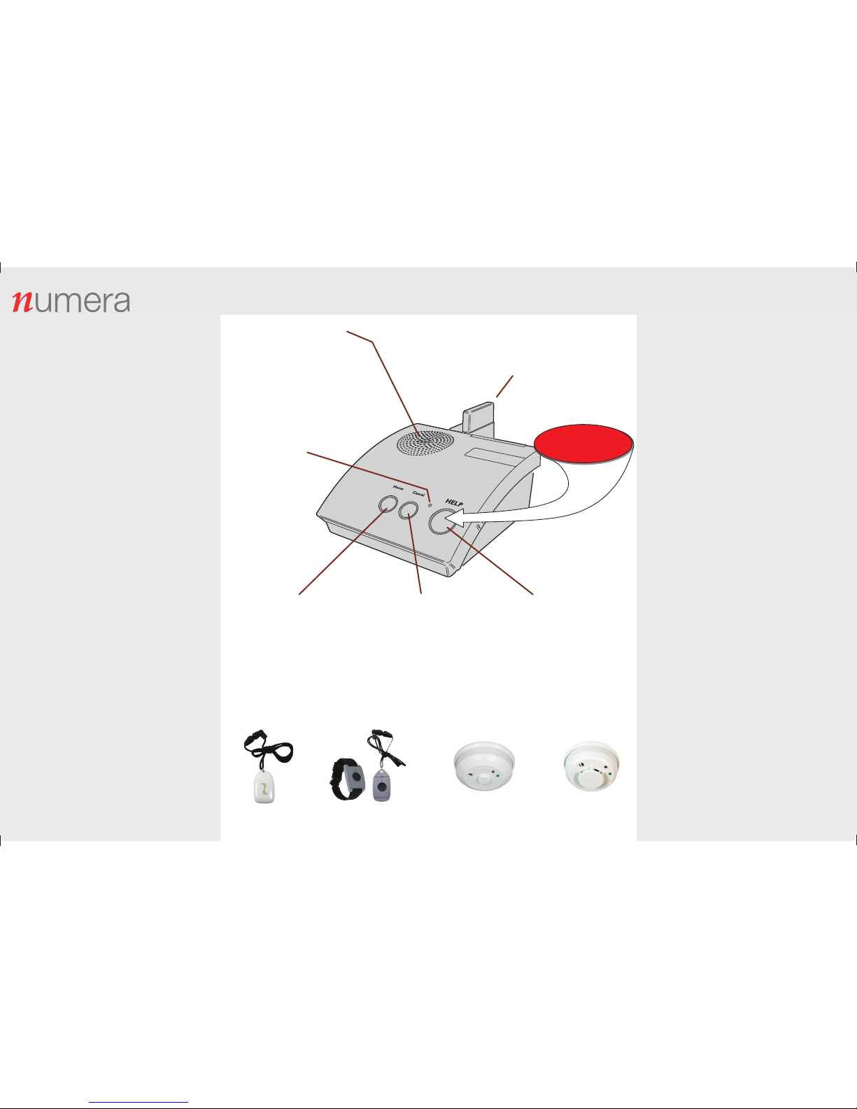
PERS Console
Wristband Sensor
2GIG-PHB1-345
Smoke Sensor
2GIG-SMKT3-345
Pendant Sensor
2GIG-PHB2-345
Carbon Monoxide Sensor
2GIG-CO3-345
HOME BUTTON / INDICATOR
• Resets the activity timer
• Press to announce the current time
• Press for 5 seconds to switch between
Home Mode and Away Mode
• Lights green in Home Mode
• Blinks green when the activity timer is running
• Flashes green when less than 15 minutes
remain on the activity timer
MICROPHONE
• Listens for your voice
• Used for 2-way communications
with monitoring service
• Used during Speakerphone Mode
SPEAKER
• Speaks voice announcements
• Sounds alarms
• Used for 2-way voice communications
with the monitoring service
• Used during Speakerphone Mode
• Sounds steady warning tone if Console fails
• Speaker volume adjustment on bottom of
the Console (must be set so announcements
can be heard from across the room)
OPTION MODULE(S)
• One or two option modules
can be installed
• Modules plug into the rear of the Console
• Option for cellular telephone reporting
• Option for a wireless remote
speaker / microphone
HELP BUTTON / INDICATOR
• Press to trigger the emergency alarm
• Press to answer an incoming call if
Speakerphone Mode is enabled
• Lights green during normal operation
• Flashes red while sending alarm
reports to the monitoring service
• Lights orange during Speakerphone Mode
• Flashes green every 3 seconds when
the Console is without AC power and
running on the backup battery
• Blinks green when the Console
battery is charging
CANCEL BUTTON / INDICATOR
• Silences a pending alarm
• Press to clear alarm and
silence announcements
• Press for 3 seconds for sensor Learn Mode
• Press to exit Test Mode or Learn Mode
• Lights yellow for sensor fault
• Blinks yellow for Console or sensor low
battery (if blinking, call for service)
• The Console’s battery is automatically
tested once a day, if the battery tests low,
a report is sent to the monitoring service
PERS-4200X Personal Emergency Reporting System Quick Guide
PRINTER’S INSTRUCTIONS:
INSTR, PERS-4200X, QUICK GUIDE, ENGLISH; P/N: 10007313 A; INK: 4/C PROCESS; MATERIAL: 20# WHITE COATED; SIZE: 11.000” x 17.000”; FOLDING: 1-FOLD VERTICAL, FINISH 8.500” X 11.000”; TOLERANCE: ± .125”; SCALE: 1-1; SIDE 1 OF 2
Personal Help Buttons
Page 2
PERS-4200X System Functions
Copyright © 2016 Nortek Security & Control LLC 10007313 A
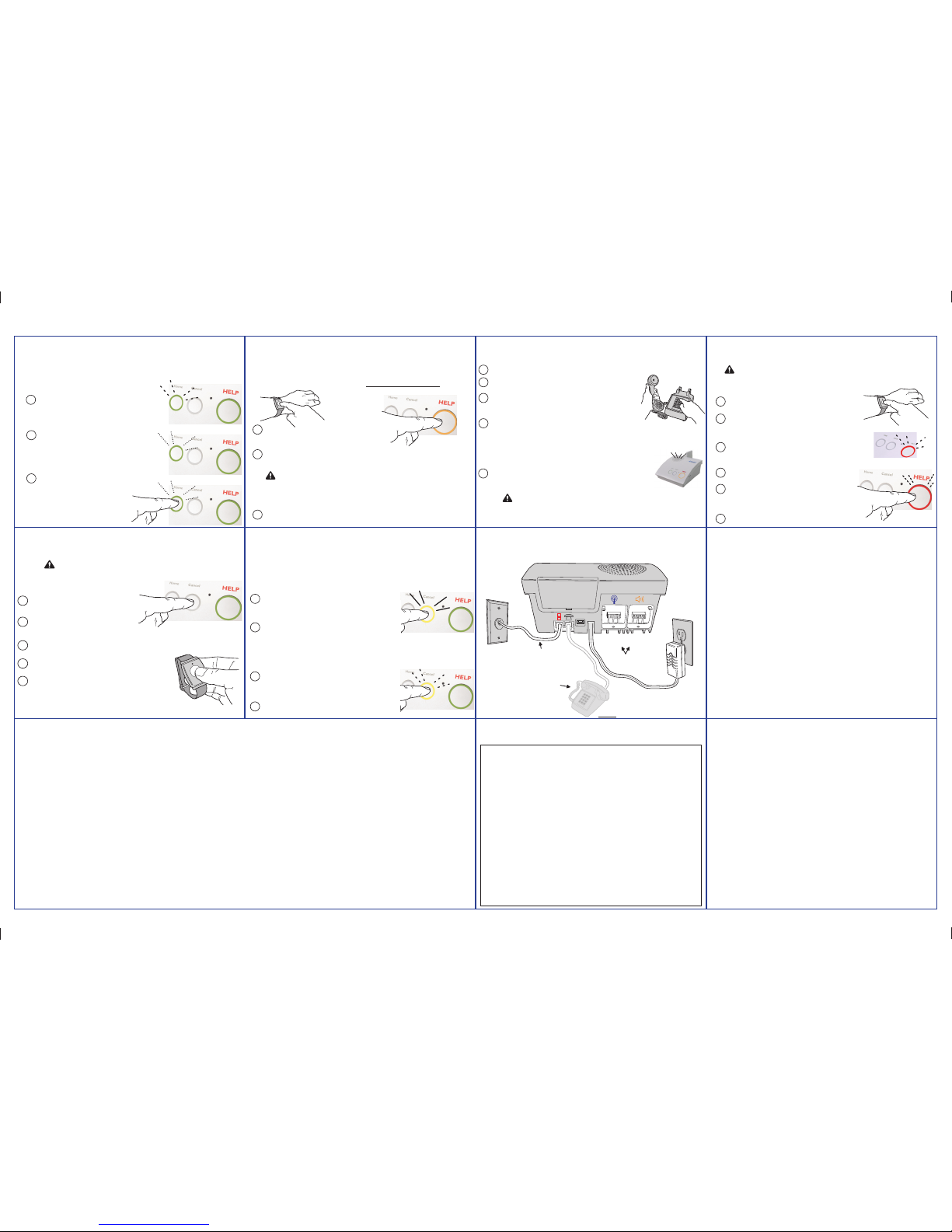
Activity Timer
Adding One Sensor
Testing Log
Remote Call-in Speakerphone Mode
System Connections
Service Information
Testing Sensors
Important Installation Warnings
Limited Warranty
Speakerphone Mode
Sensor Fault Conditions
The Console can check for lack of daily activity and
automatically call the monitoring service.
(This is an option and may not be active on your system.)
WHEN THE ACTIVITY TIMER IS RUNNING
1
2
3
The green
Home
indicator will blink, showing that
the activity timer is running. This signals you that it is
time to press the
Home
button.
When less than 15 minutes remain on the activity
timer, the green
Home
indicator will flash and the
Console announces "Activity Window Expiring" every
3 minutes.
You need to press the
Home
button or
trigger an activity sensor
before
the
timer expires to prevent an inactivity call
to the monitoring service.
WHEN THE ACTIVITY TIMER IS RUNNING OUT OF TIME
RESETTING THE ACTIVITY TIMER TO PREVENT A CALL
Your monitoring service will set the
time(s) of day that you will need to
press the
Home
button.
Pressing the
Home
button again will cause the
Console to announce the time, current Console
mode, and and trouble conditions. (Optional)
It's important to test your system weekly.
TESTING FROM A PORTABLE SENSOR
1
Press a portable sensor's button until the Console
announces "Emergency call being placed".
CAUTION: BEFORE TESTING YOURSELF, CALL THE MONITORING
SERVICE TO NOTIFY THEM THAT YOU WILL BE TESTING
Testing should be done from all portable sensors and the Console.
2
The
HELP
button will blink red and the Console will repeat
the announcement every 30 seconds until the message is
reported to the monitoring service then the Console will
announce "Emergency reported, please stand by".
3
Follow the instructions from the monitoring service dispatcher.
TESTING FROM THE CONSOLE
1
Press the Console's
HELP
button until the Console
announces "Emergency call being placed".
2
The
HELP
button will blink red and the Console will repeat
the announcement every 30 seconds until the message is
reported to the monitoring service then the Console will
announce "Emergency reported, please stand by".
3
Follow the instructions from the monitoring service dispatcher.
Emergency sensors can be added
to the Console
one at a time using these steps:
TO ADD A SENSOR
1
Press the
Cancel
button for 5 seconds.
2
The Console will announce "Ready to
learn sensor, Zone [zone number 1-16]".
3
Activate the sensor by pressing its button.
WARNING: THE CONSOLE WILL NOT BE ABLE TO REPORT
AN EMERGENCY WHILE ADDING A SENSOR
New Sensor
4
The Console will announce "[Sensor type] sensor learned".
5
After the sensor has been added, the Console will resume
normal operation and announce "Console ready".
NOTE:
In case you need to exit at Step 3 without
adding a sensor, press the
Cancel
button.
Sensors update the Console with their status.
(Status announcements will not sound while the Console is in Night Mode.)
SENSOR STATUS REPORTS
1
NOTE:
Status reports are
not monitored while the
Console is in Away Mode
Sensors can be set by the monitoring service to regulary send their
status to the Console. The regular status signals v
erify that the sensor
is working properly. The length of time that missing status signals from
a sensor cause a fault report is set by the monitoring service.
SENSOR LOW BATTERIES
2
If the Console has not received status signals from a sensor,
the yellow
Cancel
indicator will light and a report will be
sent to the monitoring service. The Console may also be
setup to announce the sensor trouble.
Press the
Cancel
button to silence the announcement and
clear the indication.
Sensors are powered by batteries. Each sensor automatically
checks its battery and if the battery is low the sensor will send a
low battery signal to the Console.
1
2
If the Console receives a low battery signal from a sensor,
the yellow
Cancel
indicator will blink and a report will be
sent to the monitoring service. The Console may also be
setup to announce the sensor trouble.
Press the
Cancel
button to silence the announcement and
clear the indication.
For service, refer to the information below.
Your Monitoring Company:
Your telephone
(
optional connection)
24-hour power outlet
(an outlet that's not
controlled by a wall switch)
(Your monitoring service will typically make these connections.)
Your telephone
wall jack
The Console connects to power and the telephone.
Console
Must be connected
unless cellular
module is used
NOTE: The local telephone or any
device connected to the console's
phone jack will be disconnected from
the telephone line while the console
is reporting to the central station
Optional plug-in
module locations
Cellular
Module
Remote
Speaker/Microphone
Module
The Console can be used as a speakerphone.
(This is an option and may not be active on your system.)
1
While the telephone is ringing, activating an
emergency pendant or pressing the Console's
HELP
button will answer the telephone.
NOTE: Speakerphone Mode can only be used on incoming calls and will not function
when the Console is operating from battery backup power. Attempting to answer
while the Console is on backup power
will cause an emergency alarm.
WARNING: THE CONSOLE WILL NOT BE ABLE TO REPORT
AN EMERGENCY WHILE THE SPEAKERPHONE IS ACTIVE
2
You can talk to the caller using the Console as a speakerphone. The
HELP
button will light
orange while the speakerphone is on.
3
When your call is finished, press the
HELP
button or press a pendant button to hang up the
telephone. (The Console has a timer that will end the call automatically after a preset time.)
NOTE: TO REPORT AN EMERGENCY WHEN THE SPEAKERPHONE IS IN USE, PRESS EITHER THE
HELP BUTTON OR A PENDANT BUTTON TO END THE PHONE CALL AND THEN PRESS ONE OF
THESE BUTTONS AGAIN TO REPORT THE EMERGENCY.
Automatic Speakerphone Mode can be started by a caller.
(This is an option and may not be active on your system.)
1
WARNING: THE CONSOLE WILL NOT BE ABLE TO REPORT
AN EMERGENCY WHILE THE SPEAKERPHONE IS ACTIVE
Call the Console's telephone number, let it ring three times, then hang up.
NOTE: TO REPORT AN EMERGENCY WHEN THE SPEAKERPHONE IS IN USE, PRESS EITHER THE
HELP BUTTON OR A PENDANT BUTTON TO END THE PHONE CALL AND THEN PRESS ONE OF
THESE BUTTONS AGAIN TO REPORT THE EMERGENCY.
2
Wait about 10 seconds, then call the Console a second time.
3
4
5
Have a conversation through the Console's speaker and microphone.
When the call is finished, press "9" to disconnect. (In case you forget to
disconnect, the Console has a timer that will end the call automati
cally after
a preset time, warning beeps will sound 5 seconds prior to disconnect.)
When the Console answers, a tone will sound for 8 seconds. When
the tone ends enter the 4-digit password (1-2-3-4) or _____ followed
by the "#" key. (You have 30 seconds to enter the password.)
NOTE:
During the call, the caller can use the "1" and "3" keys on the telephone to
switch from the automatic 2-way voice mode to manual control of the call direction
(in case a loud room noise near the Console is preven
ting hearing the caller). Press
"1" to talk, press "3" to listen. Press "8" to return to automatic 2-way voice mode.
During manual control, the Console will disconnect after 90 seconds if no keys are
pressed (warning beeps will sound 5 seconds prior to th
e disconnect).
• Be sure and test your system weekly.
• Do not bring any electrical appliances or electrical
noise generating devices (fl uorescent lamps,
motors, etc.) near the Console.
• Do not use ammonia, benzene, thinner, or similar
solvents, or abrasive powder to clean the housing
of the Console or Pendant. Clean by wiping with a
damp, soft cloth.
• The Console should be kept free of dust and
moisture.
• The Console should not be located where direct
sunlight will shine on it.
• Avoid locating the Console in extremely hot or cold
locations.
___________ ___________ ___________
___________ ___________ ___________
___________ ___________ ___________
___________ ___________ ___________
___________ ___________ ___________
___________ ___________ ___________
___________ ___________ ___________
___________ ___________ ___________
___________ ___________ ___________
___________ ___________ ___________
___________ ___________ ___________
___________ ___________ ___________
___________ ___________ ___________
___________ ___________ ___________
___________ ___________ ___________
___________ ___________ ___________
___________ ___________ ___________
___________ ___________ ___________
Each time the system is tested, write down the date.
This Nortek Security & Control product is warranted against defects in material and workmanship for twelve (12) months. This
warranty extends only to wholesale customers who buy direct from Nortek Security & Control or through Nortek Security & Control’s
normal distribution channels. Nortek Security & Control does not warrant this product to consumers. Consumers should inquire
from their selling dealer as to the nature of the dealer’s warranty, if any. There are no obligations or liabilities on the part of
Nortek Security & Control LLC for consequential damages arising out of or in connection with use or performance of this
product or other indirect damages with respect to loss of property, revenue, or profi t, or cost of removal, installation, or
reinstallation. All implied warranties, including implied warranties for merchantability and implied warranties for fi tness, are valid only
until the warranty expires. This Nortek Security & Control LLC Warranty is in lieu of all other warranties express or implied.
All products returned for warranty service require a Return Product Authorization Number (RPA#). Contact Nortek Security & Control
Returns at 1-855-546-3351 for an RPA# and other important details.
Important Wireless Information
Radio controls provide a reliable communications link and fi ll an important need in portable wireless signaling. However, there are some
limitations which must be observed.
This device complies with Industry Canada and Part 15 of the FCC Rules. Operation is subject to the following two conditions: (1) This
device may not cause harmful interference, and (2) This device must accept any interference received, including interference that may
cause undesired operation.
• Le présent appareil est conforme aux CNR d’Industrie Canada applicables aux appareils radio exempts de licence. L’exploitation
est autorisée aux deux conditions suivantes : (1) l’appareil ne doit pas produire de brouillage, et (2) l’utilisateur de l’appareil doit
accepter tout brouillage radioélectrique subi, même si le brouillage est susceptible d’en compromettre le fonctionnement.
The antenna used for the transmitter must be installed to provide a separation distance of at least 7.87 inches (20 cm) from all persons, and must
not be co-located or operating in conjunction with any other antenna or transmitter other than those supplied with the PERS-4200X console.
• L’antenne de l’émetteur doit être installé à une distance d’au moins 7,87 pouces (20 cm) de toutes les personnes, et ne doit pas être
placé ou utilisé en conjonction avec toute autre antenne ou tout autre émetteur autres que ceux fournis avec la console PERS-4200X.
• For U.S. installations only: The radios are required to comply
with FCC Rules and Regulations as Part 15 devices. As such,
they have limited transmitter power and therefore limited range.
• A receiver cannot respond to more than one transmitted signal
at a time and may be blocked by radio signals that occur on or
near their operating frequencies, regardless of code settings.
• Changes or modifi cations to the device may void FCC compliance.
• Infrequently used radio links should be tested regularly to
protect against undetected interference or fault.
• A general knowledge of radio and its vagaries should be
gained prior to acting as a wholesale distributor or dealer, and
these facts should be communicated to the ultimate users.
PRINTER’S INSTRUCTIONS:
INSTR, PERS-4200X, QUICK GUIDE, ENGLISH; P/N: 10007313 A; INK: 4/C PROCESS; MATERIAL: 20# WHITE COATED; SIZE: 11.000” x 17.000”; FOLDING: 1-FOLD VERTICAL, FINISH 8.500” X 11.000”; TOLERANCE: ± .125”; SCALE: 1-1; SIDE 2 OF 2
 Loading...