

Page 1
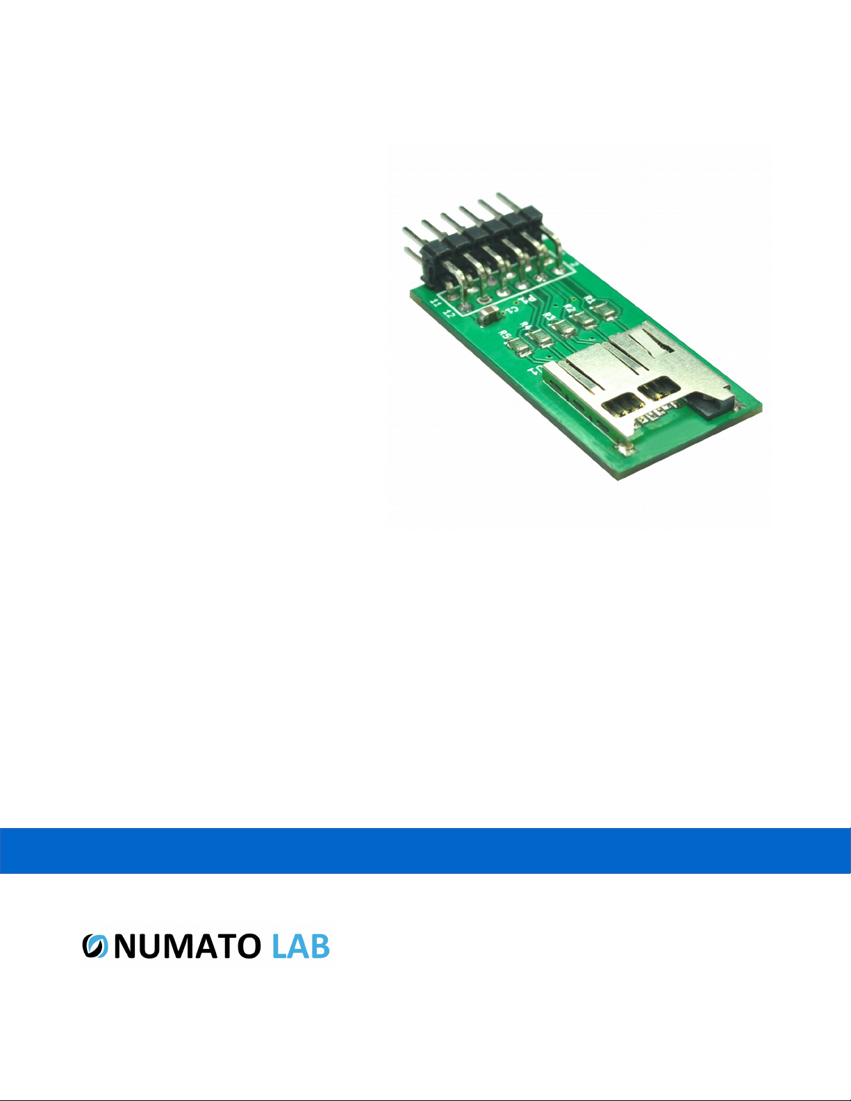
MICRO SD Expansion Module
User Guide
www.numato.com
Rev 9
Page 2

Get in touch with us!
Please feel free to send a mail to one of the mail IDs below or use the Contact Us page at
http://www.numato.com to drop us a quick message.
Technical Help
Got technical questions? Please write to [email protected]
Sales Team
Questions about making payments, volume discounts, academic/open source discounts, purchase
orders and quotes? Please write to [email protected]
Webmaster
Questions/Suggestions about our website? Please write to [email protected]
Like us on Facebook! https://www.facebook.com/numato
Visit our blog http://www.numato.cc for news, updates and specials.
Mailing Address
Numato Systems Pvt Ltd
1st Floor, #56C Wipro Avenue
Phase 1 - Electronic City
Bangalore, KA-560100, India
* Mail orders, phone orders and direct pick up are not available at this time. Please visit our online store to place your order. Estimated shipping time to
your address will be displayed in the shopping cart before checkout.
You may use, modify or share this publication or part of thereof adhering to Creative
Commons Attribution-ShareAlike 3.0 Unported (CC BY-SA 3.0) License.
See complete license text at http://creativecommons.org/licenses/by-sa/3.0/
All trademarks are property of their respective owners.
Page 3

1 Micro SD Expansion Module – User Guide
Introduction
Micro SD Expansion Module provides an easy and convenient way to interface Micro SD card to
Numato Lab’s FPGA/Micro-controller boards. It can be connected to any FPGA/Micro-controller board
featuring 2x6 pin Expansion connector. This module can be manually wired to FPGA/Micro-controller
boards that does not have 2x6 expansion header.
Applications
• Product Prototype Development
• Development and testing of custom Projects
• Audio playback device development
• Data logging
Board features
• Micro SD card slot
• 2x6 pin expansion connectors
• Dimension: 19mm X 38mm
©2015 NUMATO SYSTEMS PVT LTD
www.numato.com
Page 4
2 Micro SD Expansion Module – User Guide
How to use the module
The following section describes how to use this module.
Components/Tools required
Along with the module, you may need the items in the list below for easy and fast installation.
1. Any FPGA board featuring a 2x6 pin Expansion connector
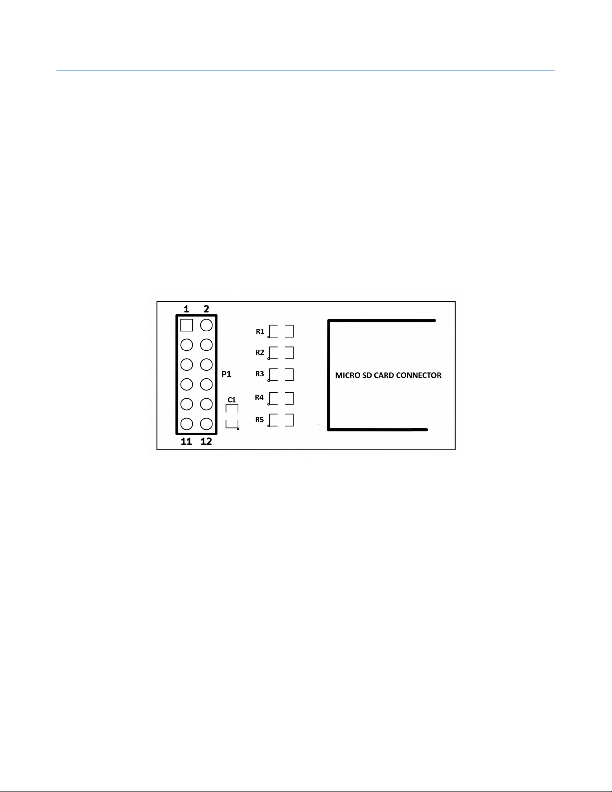
Connection Diagram
This diagram should be used as a reference only. For detailed information, see the schematics at the
end of this document. Details of individual connectors are as below.
To use this module, directly attach the 2x6 expansion connector to the FPGA/Micro-controller
development board where corresponding female header is available. If 2x6 female header is not
available, manually make the connections as per the connection details below.
©2015 NUMATO SYSTEMS PVT LTD
www.numato.com
Page 5
3 Micro SD Expansion Module – User Guide
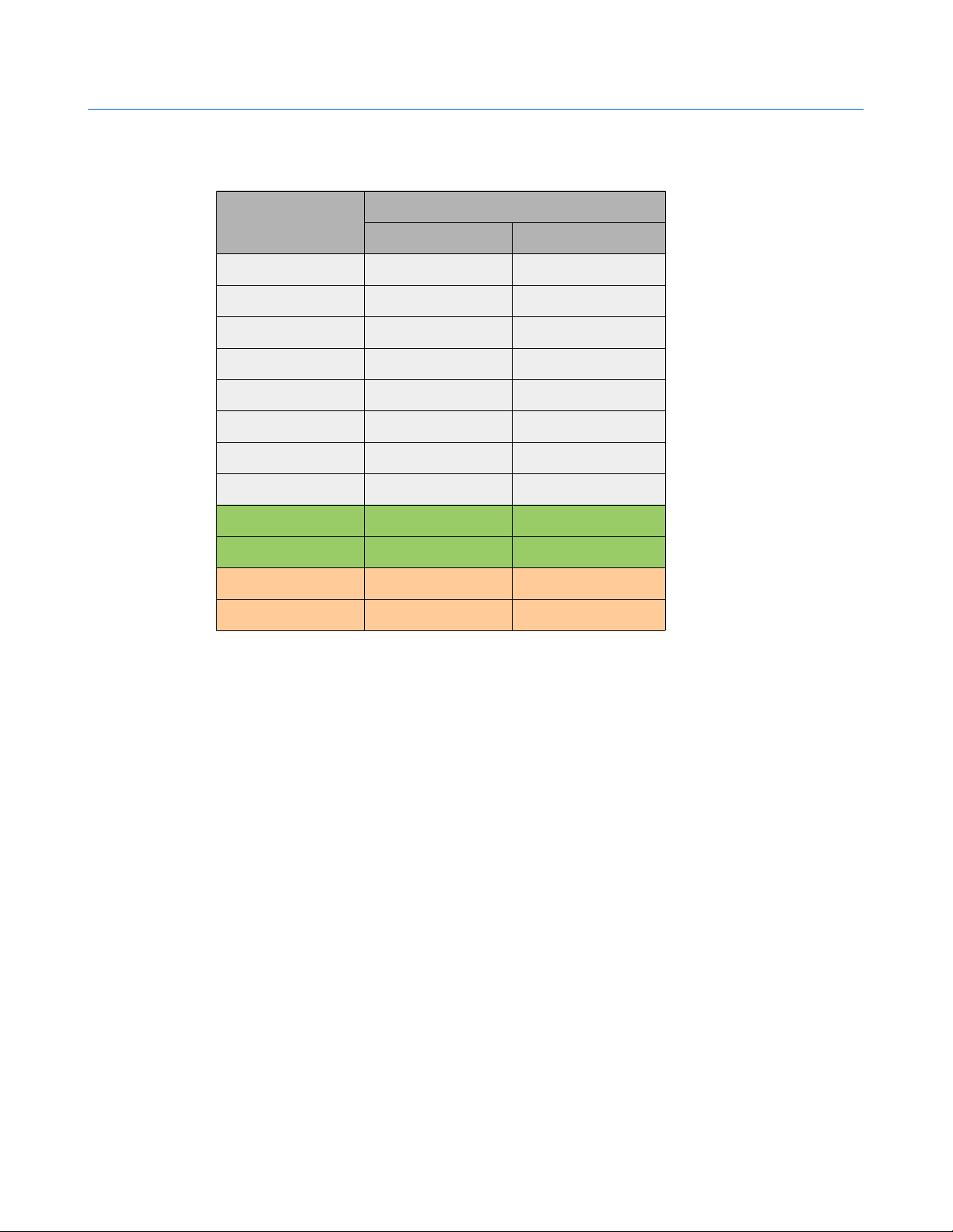
Connection Details
Header P1
Header Pin No. Pin Details
SD MODE SPI MODE
1 DAT3 CS
2 DAT2 -
3 CLK SCLK
4 CMD DI
5 DAT1 -
6 DAT0 DO
7 - -
8 - -
9 GND GND
10 GND GND
11 VCC3V3 VCC3V3
12 VCC3V3 VCC3V3
For more information, refer the schematics below.
©2015 NUMATO SYSTEMS PVT LTD
www.numato.com
Page 6
4 Micro SD Expansion Module – User Guide
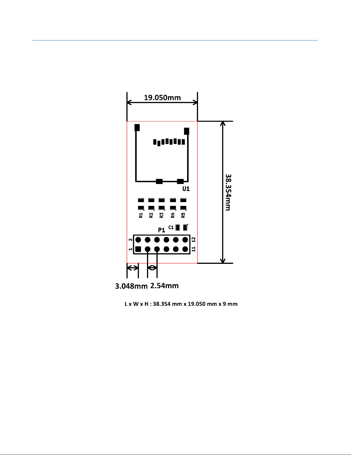
Physical Dimensions
Schematics
See next page
©2015 NUMATO SYSTEMS PVT LTD
www.numato.com
Page 7
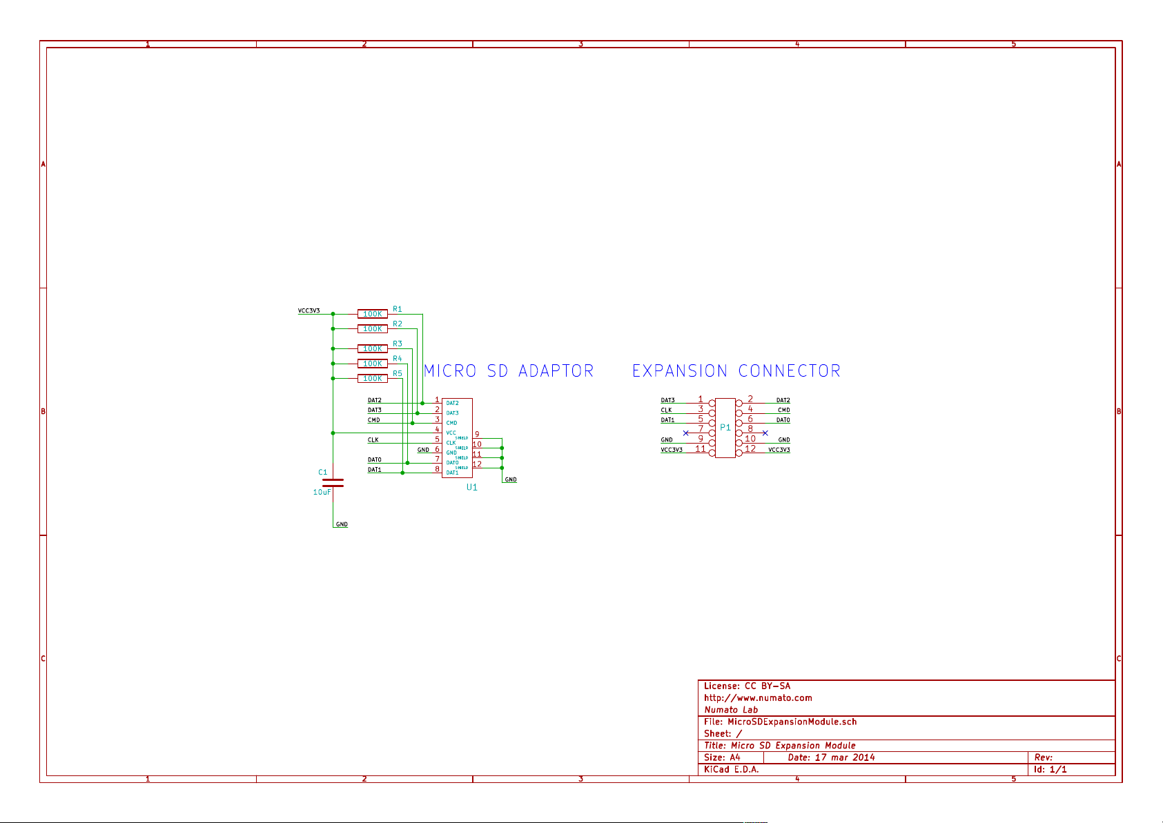
1
2
3
4
5
A A
VCC3V3
B B
C1
10uF
GND
100K
100K
100K
100K
100K
DAT2
DAT3
CMD
CLK
DAT0
DAT1
R1
R2
R3
R4
R5
1
DAT2
2
DAT3
3
CMD
4
VCC
9
SHIELD
5
CLK
10
SHIELD
GND
6
GND
11
SHIELD
7
DAT0
12
SHIELD
8
DAT1
GND
U1
EXPANSION CONNECTORMICRO SD ADAPTOR
1 2
DAT3 DAT2
3 4
CLK CMD
5 6
DAT1 DAT0
7 8
9 10
11 12
P1
GNDGND
VCC3V3VCC3V3
C C
License: CC BY-SA
http://www.numato.com
Numato Lab
File: MicroSDExpansionModule.sch
Sheet: /
Title: Micro SD Expansion Module
1
2
3
KiCad E.D.A.
4
Date: 17 mar 2014
Rev: Size: A4
Id: 1/1
5
 Loading...