

Page 1
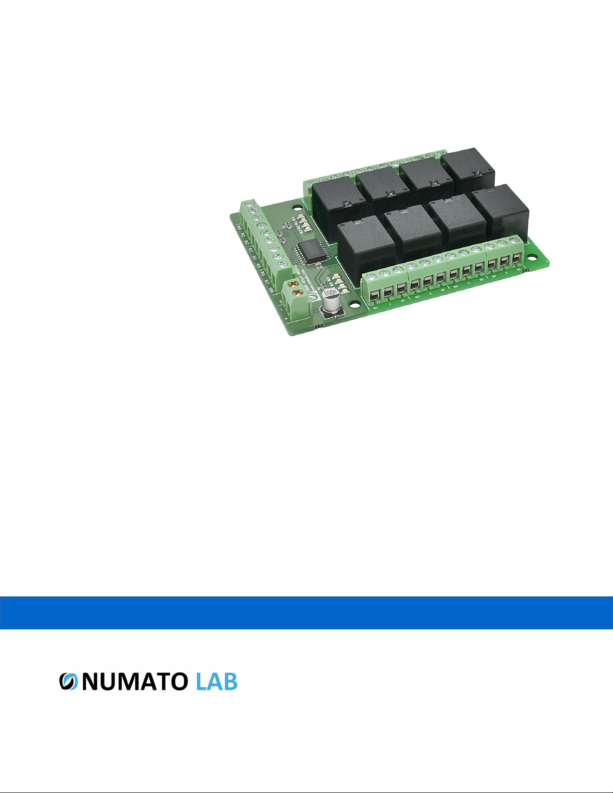
8 Channel Relay Controller Board
User Guide
www.numato.com
Rev 9
Page 2

Get in touch with us!
Please feel free to send a mail to one of the mail IDs below or use the Contact Us page at
http://www.numato.com to drop us a quick message.
Technical Help
Got technical questions? Please write to [email protected]
Sales Team
Questions about making payments, volume discounts, academic/open source discounts, purchase
orders and quotes? Please write to [email protected]
Webmaster
Questions/Suggestions about our website? Please write to [email protected]
Like us on Facebook! https://www.facebook.com/numato
Visit our blog http://www.numato.cc for news, updates and specials.
Mailing Address
Numato Systems Pvt Ltd
1st Floor, #56C Wipro Avenue
Phase 1 - Electronic City
Bangalore, KA-560100, India
* Mail orders, phone orders and direct pick up are not available at this time. Please visit our online store to place your order. Estimated shipping time to
your address will be displayed in the shopping cart before checkout.
You may use, modify or share this publication or part of thereof adhering to Creative
Commons Attribution-ShareAlike 3.0 Unported (CC BY-SA 3.0) License.
See complete license text at http://creativecommons.org/licenses/by-sa/3.0/
All trademarks are property of their respective owners.
Page 3

1 8 Channel Relay Controller Board – User Guide
Introduction
Numato Lab's 8 Channel Controller Board is a smart choice for controlling higher current loads from
your micro controller development board or a PC parallel port. This board has eight on-board relays
which can switch up to 10A. All relay terminals (C, NC, NO) are accessible through screw terminals
which makes wiring up the board very easy. The relays are driven by popular darlington array
ULN2803. Relay coil is rated for 12VDC.
Some of the possible uses of this module include
• Home Automation
• Lighting Control
• Garden Equipment Control
• Industrial Automation
• Test Fixtures
• DIY and Hobby
This module has eight on board relays and associated drivers capable of controlling a large number of
devices including lamps, motors, locks etc...
Features
• Very compact and easy to wire up.
• Connects directly to TTL devices (Microcontrollers, Arduino etc..).
• Eight Relays with three pin screw terminals for easy connectivity.
©2015 NUMATO SYSTEMS PVT LTD
www.numato.com
Page 4
2 8 Channel Relay Controller Board – User Guide
How to use the module
The following section describes how to use this module.
Components/Tools required
Along with the module, you may need the items in the list below for easy and fast installation.
1. 12V DC supply.
2. Medium size screw driver.
Connection Details
IMPORTANT Please exercise utmost caution while working with electrical mains or other
high voltages. Failure to comply with safety regulations may result in injury and or death.
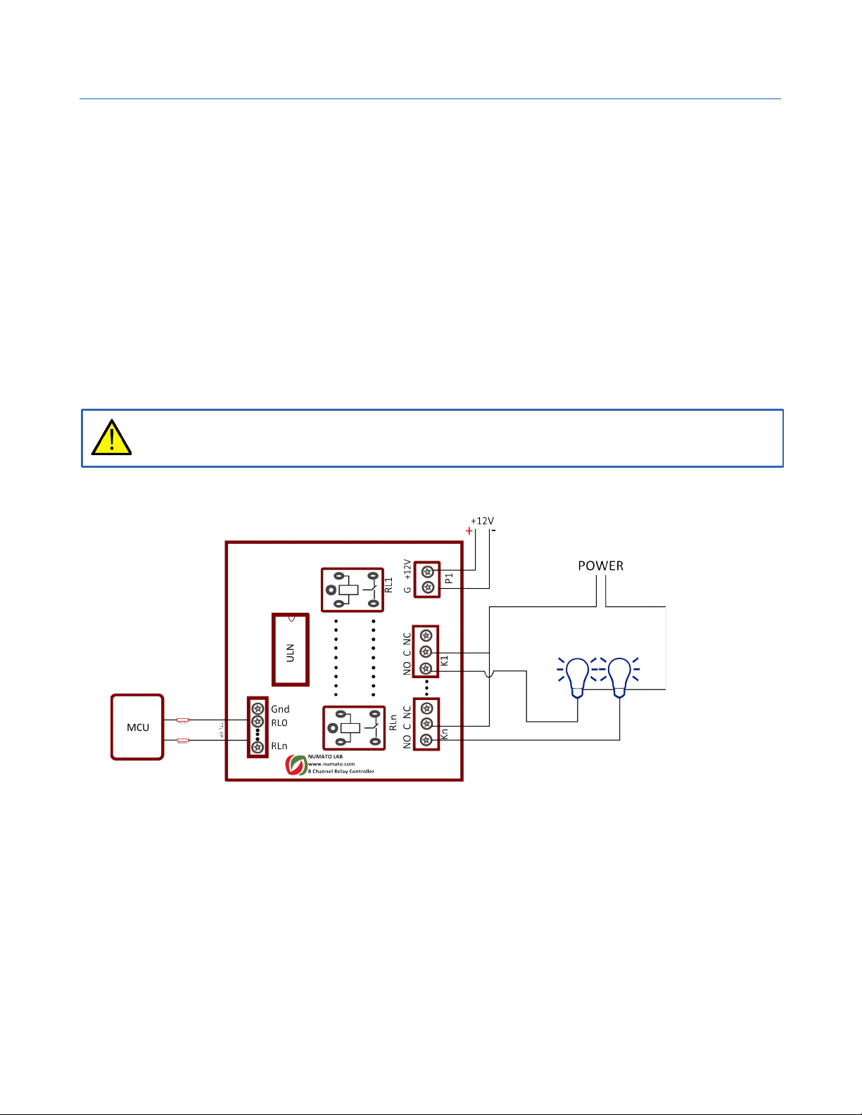
Connection Diagram
Above image shows basic connection diagram that can be used in most of the situations. The
connection diagram is same for both AC and DC loads. Please make sure to use a freewheeling diode
or snubber circuit if the load is inductive. More details about using inductive loads is available
elsewhere in this document. It is important to make sure that the wires used to connect loads are
sufficiently rated to handle expected load current. Exercise caution while working with high voltages.
The following sections identify individual connections in detail.
©2015 NUMATO SYSTEMS PVT LTD
www.numato.com
Page 5
3 8 Channel Relay Controller Board – User Guide
Relay Contacts
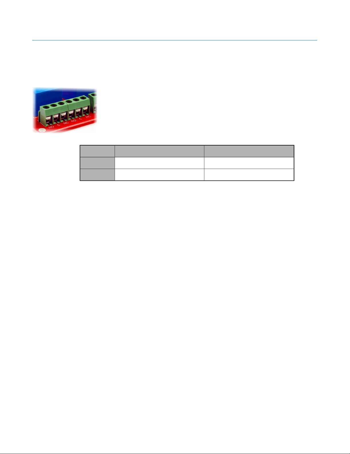
All contacts on each relay is available externally on screw terminals for easy user access. The relays are
rated for AC and DC supply voltages. Please see the electrical parameter table for more details. Each
relay has three contacts(C, NO and NC). C is the common terminal and is
used in both normally open and normally closed positions. The contacts NC
and C will be connected when the relay is turned off and will be
disconnected when relay is turned on. And vice versa, the contacts C and
NO will be disconnected when relay is turned off and will be connected
when the relay is turned on. Table below summarizes possible relay contact
positions.
Relay State Connection between NC and C Connection between NO and C
OFF Close Open
ON Open Close
DC Power Supply
This module uses +12V supply for the relay coils. The +12V supply for the relay coils is not optional
and the relay will not switch without this supply. Any off the shelf 12V DC power supply can be used
for this purpose. Make sure to connect the power supply in correct polarity. Connect the positive
terminal of the power supply to the +12 terminal on the module. Connect negative terminal of the
power supply to GND terminal of the module. Connecting power supply incorrectly can cause damage
to the module and/or other devices.
©2015 NUMATO SYSTEMS PVT LTD
www.numato.com
Page 6
4 8 Channel Relay Controller Board – User Guide
Triggering Relay
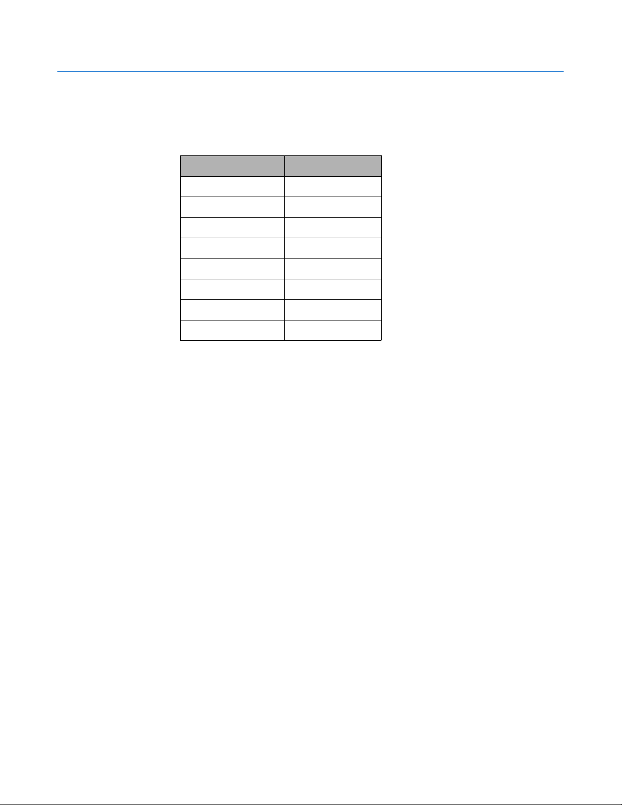
The relays on the board can be either turned on by using micro controller or DC power supply with a
Series resistor 2.2K ohm. The triggering pins are marked as RL0 to RL7 respectively.
Trigger In Relay
RL0 Relay 0
RL1 Relay 1
RL2 Relay 2
RL3 Relay 3
RL4 Relay 4
RL5 Relay 5
RL6 Relay 6
RL7 Relay 7
©2015 NUMATO SYSTEMS PVT LTD
www.numato.com
Page 7
5 8 Channel Relay Controller Board – User Guide
Additional Information
Using relay modules with inductive loads
It is important to take additional care when using relays with inductive loads. An inductive load is
pretty much anything that has a coil and works based on magnetic principles like Motors, Solenoids
and transformers. Inductive loads produce back emf when the magnitude of the load current changes.
The back emf can be in the order of tens or even hundreds of voltage (See this Wikipedia article
http://en.wikipedia.org/wiki/Counter-electromotive_force). This effect is most severe when power is
disconnected from inductive load because the rate of change of current is maximum at that point.
Even though the back emf lives only for a very short time (a few milliseconds) it can cause sparks
between the relay contacts and can deteriorate the contact quality over time and reduce the life span
for the relays considerably.
So it is important to take countermeasures to suppress the back emf to acceptable levels to protect
relay contacts. Usually this requires connecting electronic devices in parallel with the load such that
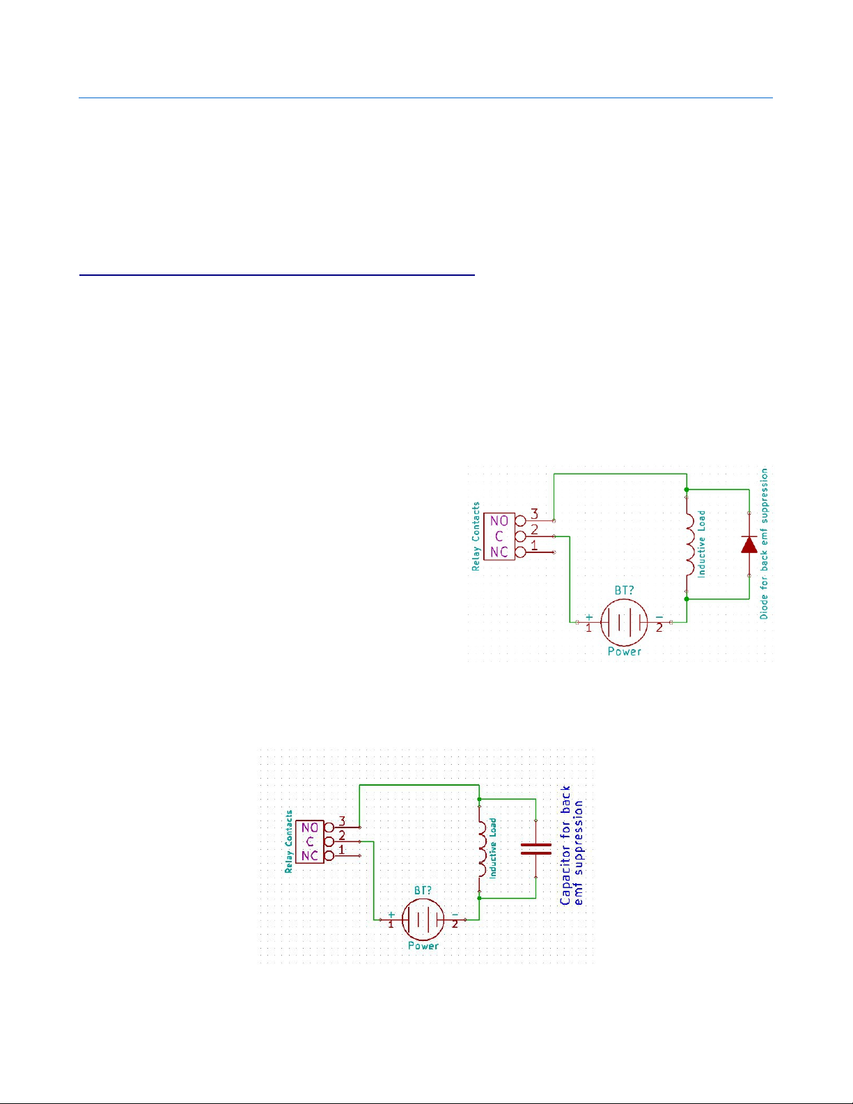
they absorb the high voltage components generated by the load. For solenoids, connecting a diode
(fast switching diode is recommended) in parallel to the
load (in reverse direction to the load current) is very
effective. A diode used for this purpose is usually called
a freewheeling diode. Please see the diagram on the
right for connection details.
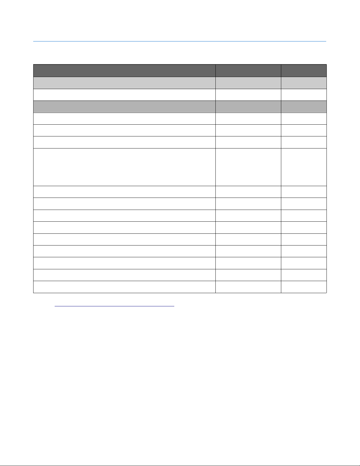
A capacitor with proper rating is recommended for protecting the relay contacts when a motor is used
as load. The capacitor should be rated enough to withstand the back emf that is generated by the
motor. Please see the diagram below for connection details.
©2015 NUMATO SYSTEMS PVT LTD
www.numato.com
Page 8

6 8 Channel Relay Controller Board – User Guide
Please note that the relay modules are NOT shipped with back emf suppression devices pre-installed.
The exact kind of suppression device and the parameters of the selected device can vary depending
on the load itself. Some of the parameters that affects the suppression device selection are the
inductance of the load, power supply voltage, load current, physical size/structure of the load etc.. It
is obvious that it is impossible for us to predict these parameters and design required back emf
suppression device and incorporate that on the board. So we believe this is a task best left to the
module user. There is an excellent article on designing back emf suppression on Wikipedia at
http://en.wikipedia.org/wiki/Flyback_diode
©2015 NUMATO SYSTEMS PVT LTD
www.numato.com
Page 9
7 8 Channel Relay Controller Board – User Guide
Technical Specifications
Parameter * Value Unit
Basic Specifications
Number of relays 8
Relay Specifications
Nominal relay coil voltage 12 V
Nominal coil power consumption (per relay) 360 mW
Relay contact material Silver Alloy
Contact rating 1A: 10A 240VAC/ 12A
120VAC
1C: 7A 240VAC/ 10A
120VAC
Maximum switching voltage 250VAC/ 30VDC
Maximum switching current 15 A
Maximum switching power 2770VA/ 240W
Contact resistance (initial) 100 Min at 6VDC 1A mΩ
Life expectancy (Electrical) 100,000 Operations
Life expectancy (Mechanical) 10,000,000 Operations
Nominal insulation resistance 100 Min at 500VDC MΩ
Maximum switching on response time 10 mS
Maximum switching off response time 5 mS
* All parameters considered nominal. Numato Systems Pvt Ltd reserve the right to modify products without notice.
* http://kyotarelays.com/datasheets/KT%20603.pdf
©2015 NUMATO SYSTEMS PVT LTD
www.numato.com
Page 10

8 8 Channel Relay Controller Board – User Guide
FAQ
Q. I need a customized version of this product, can Numato do the customization for me?
A. Yes, we can definitely do customization but there may be minimum order requirements depending on the level of
customization required. Please write to [email protected] for a quote.
Q. Where can I buy this product?
A. All Numato products can be ordered directly from our web store http://www.numato.com. We accept major credit
cards and Paypal and ship to almost all countries with a few exceptions. We do have distributors in many countries where
you can place your order. Please find the current list of distributors at http://numato.com/distrib.
©2015 NUMATO SYSTEMS PVT LTD
www.numato.com
Page 11
9 8 Channel Relay Controller Board – User Guide
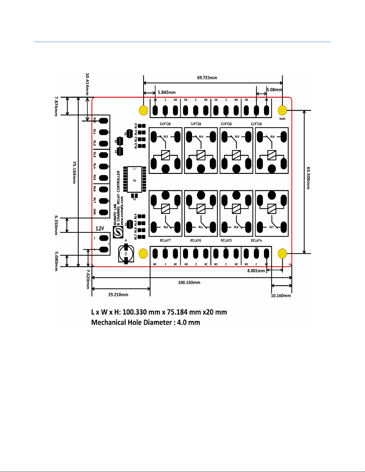
Physical Dimensions
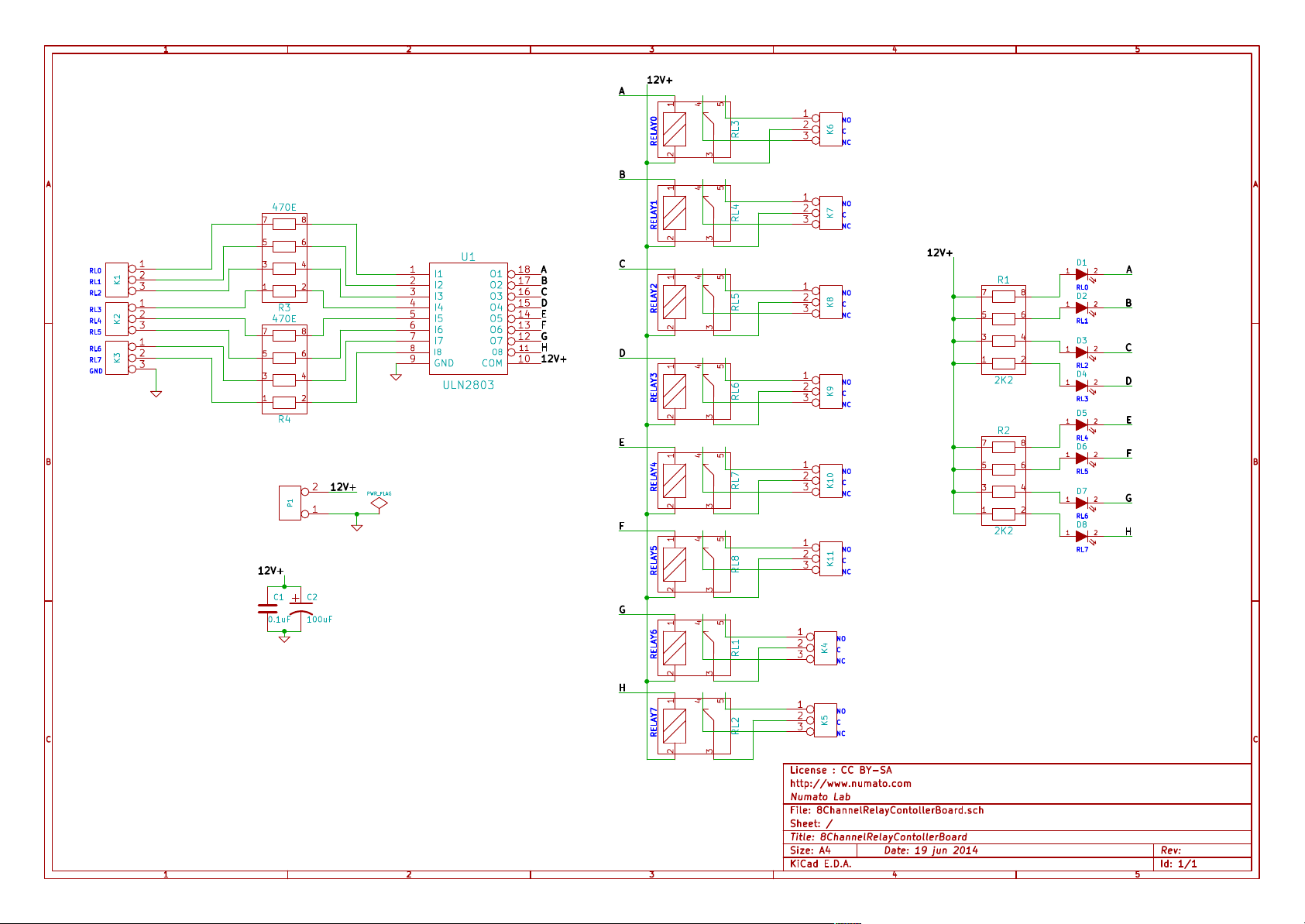
Schematics
See next page.
©2015 NUMATO SYSTEMS PVT LTD
www.numato.com
Page 12
1
2
3
12V+
A
1234
RELAY0RELAY1RELAY3RELAY4RELAY5RELAY6RELAY7 RELAY2
5
RL3
1
NO
2
C
K6
3
NC
4
5
A A
470E
7 8
5 6
RL0
RL1
RL2
RL3
RL4
RL5
RL6
RL7
GND
1
2
K1
3
1
2
K2
3
1
2
K3
3
3 4
1 2
R3
470E
7 8
5 6
3 4
1 2
1
2
3
4
5
6
7
8
U1
I1
I2
I3
I4
I5
I6
I7
I8
GND9COM
ULN2803
O1
O2
O3
O4
O5
O6
O7
A
18
B
17
C
16
D
15
E
14
F
13
G
12
H
11
O8
12V+
10
R4
B B
12V+
2
P1
1
PWR_FLAG
12V+
C1
C2
+
0.1uF
100uF
B
C
D
E
F
G
1234
1234
1234
1234
1234
1234
5
RL4
5
RL5
5
RL6
5
RL7
5
RL8
5
RL1
1
NO
2
C
K7
3
NC
12V+
1
NO
2
C
K8
3
NC
1
NO
2
C
K9
3
NC
1
NO
2
C
K10
3
NC
1
NO
2
C
K11
3
NC
1
NO
2
C
K4
3
NC
R1
7 8
5 6
3 4
1 2
2K2
R2
7 8
5 6
3 4
1 2
2K2
D1
1 2
RL0
D2
1 2
RL1
D3
1 2
RL2
D4
1 2
RL3
D5
1 2
RL4
D6
1 2
RL5
D7
1 2
RL6
D8
1 2
RL7
A
B
C
D
E
F
G
H
H
C C
1234
5
RL2
1
NO
2
C
K5
3
NC
License : CC BY-SA
http://www.numato.com
Numato Lab
File: 8ChannelRelayContollerBoard.sch
Sheet: /
Title: 8ChannelRelayContollerBoard
1
2
3
KiCad E.D.A.
4
Date: 19 jun 2014
Rev: Size: A4
Id: 1/1
5
 Loading...