

Page 1
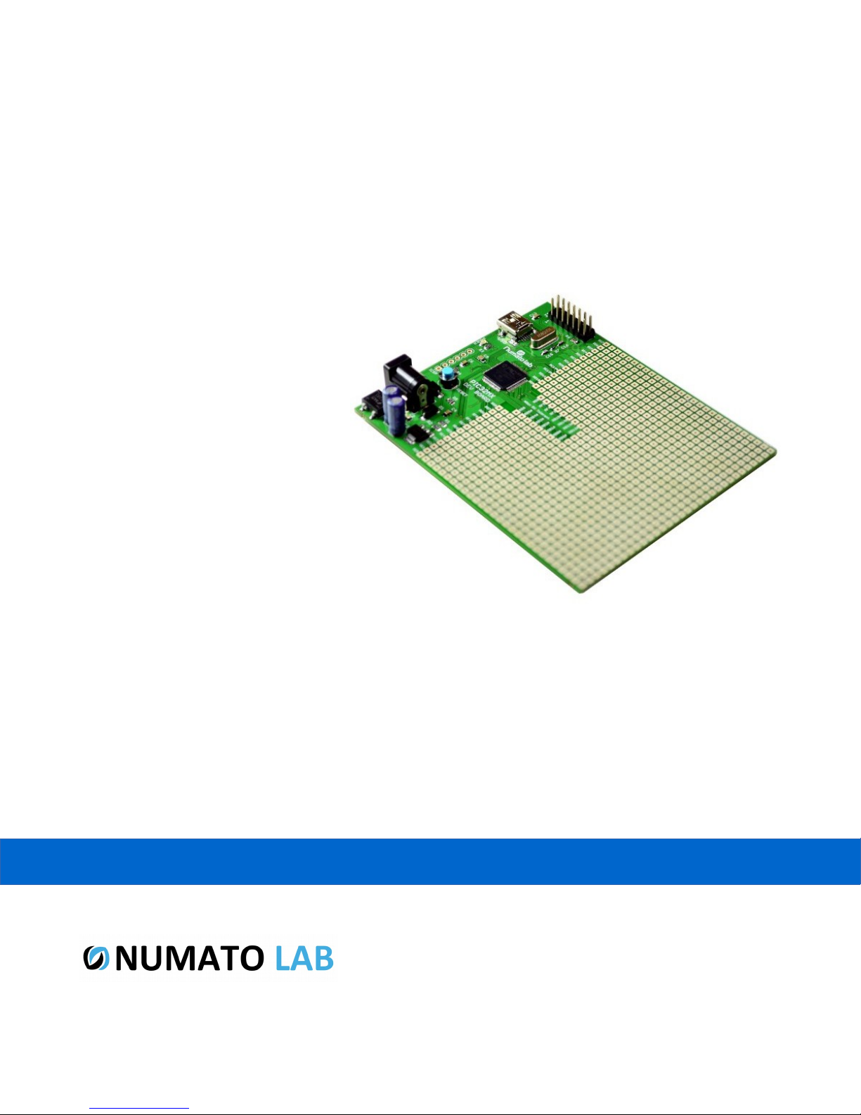
PIC32 MX Microcontroller Development Board
User Guide
www.numato.com
Rev 9
Page 2

Get in touch with us!
Please feel free to send a mail to one of the mail IDs below or use the Contact Us page at
http://www.numato.com to drop us a quick message.
Technical Help
Got technical questions? Please write to [email protected]
Sales Team
Questions about making payments, volume discounts, academic/open source discounts, purchase
orders and quotes? Please write to [email protected]
Webmaster
Questions/Suggestions about our website? Please write to [email protected]
Like us on Facebook! https://www.facebook.com/numato
Visit our blog http://www.numato.cc for news, updates and specials.
Mailing Address
Numato Systems Pvt Ltd
1st Floor, #56C Wipro Avenue
Phase 1 - Electronic City
Bangalore, KA-560100, India
* Mail orders, phone orders and direct pick up are not available at this time. Please visit our online store to place your order. Estimated shipping time to
your address will be displayed in the shopping cart before checkout.
You may use, modify or share this publication or part of thereof adhering to Creative
Commons Attribution-ShareAlike 3.0 Unported (CC BY-SA 3.0) License.
See complete license text at http://creativecommons.org/licenses/by-sa/3.0/
All trademarks are property of their respective owners.
Page 3

1 PIC32 MX Microcontroller Development Board – User Guide
Introduction
Numato Lab's PIC32 MX Development board with Microchip HID boot loader preprogrammed is a
versatile product for controlling electrical and electronic devices remotely from a PC over USB link.
This board can be conveniently powered by USB or by an external power supply for standalone
applications. Preprogrammed boot loader helps you to start testing your programs without even
buying a programmer. Ease of use and wider operating system compatibility are the primary goals
behind this product's design. Built in USB to serial conversion allows the module to be used without
any USB specific knowledge.
Features
• PIC32MX795F512H 64 pin 32 bit MIPS based microcontroller.
• 512K Program memory and 128K data RAM.
• Up to 80MHZ system clock.
• High speed GPIOs (Can toggle at 80MHZ speed).
• 1.6mm FR4 board with top and bottom White silk screen.
• USB Mini connector.
• Powered from USB or external 5V supply.
• Large board Ample prototyping area.
• Board size 3.9×3.15”(100×80mm).
• ICSP/ICD header compatible with pic kit and other popular programmers.
• On board 3.3V precision voltage regulator.
• 8MHZ crystal.
©2015 NUMATO SYSTEMS PVT LTD
www.numato.com
Page 4
2 PIC32 MX Microcontroller Development Board – User Guide
How to use the module
The following section describes how to use this module.
Components/Tools required
Along with the module, you may need the items in the list below for easy and fast installation.
1. USB A to Mini B cable.
2. Medium size Philips screw driver.
Connection Details
IMPORTANT Please exercise utmost caution while working with electrical mains or other
high voltages. Failure to comply with safety regulations may result in injury and or death.
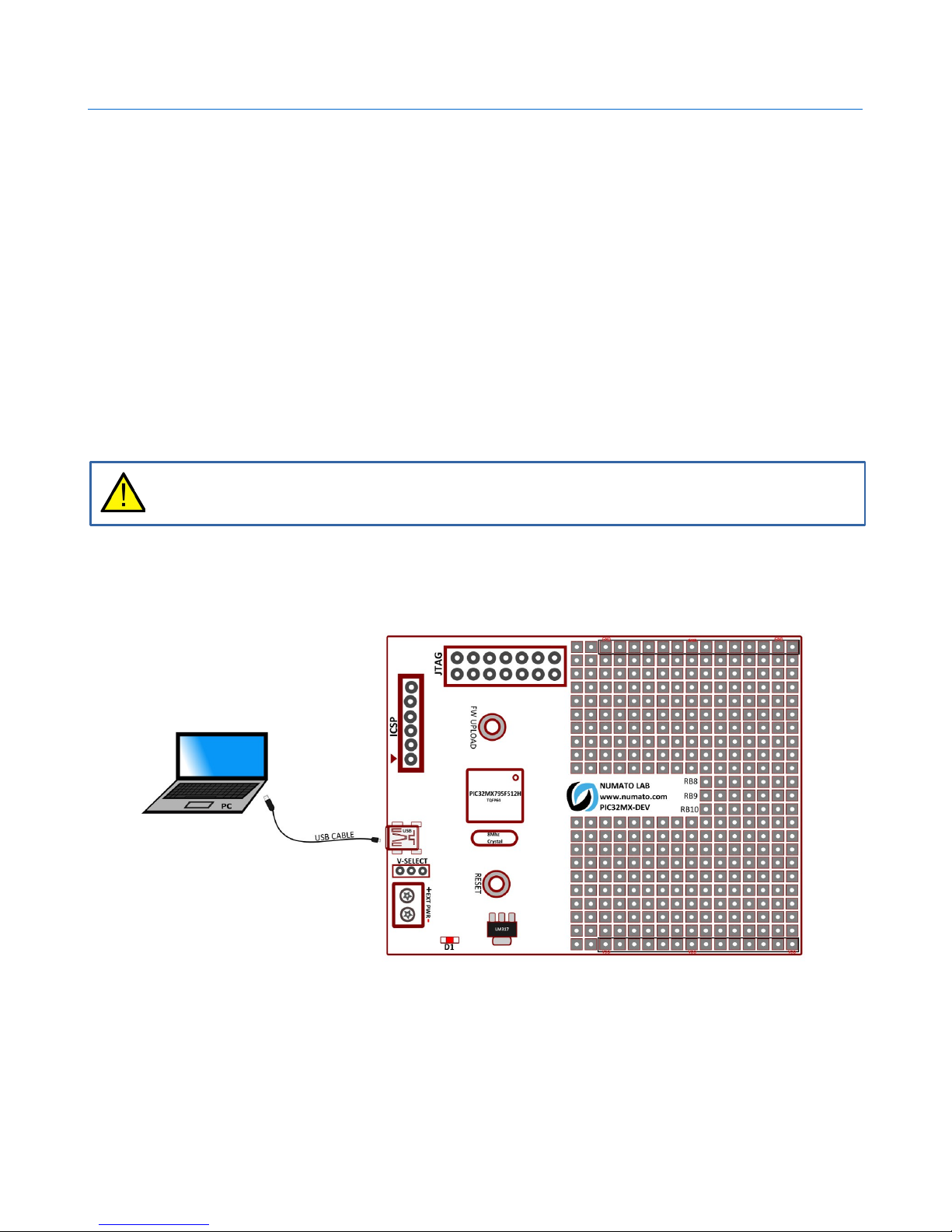
Connection Diagram
Above image shows basic connection diagram that can be used in most of the situations. Use a USB A
to Mini B cable for connection to PC. The following sections identify individual connections in detail.
©2015 NUMATO SYSTEMS PVT LTD
www.numato.com
Page 5
3 PIC32 MX Microcontroller Development Board – User Guide
USB Interface
The on board full speed USB controller helps a PC/Linux computer to communicate and
control this module seamlessly. Use a USB A to Mini B cable to connect with a PC. By
default, the logic section of the module is powered from USB so make sure not to
overcrowd unpowered USB hubs(the picture on the right shows USB Mini B connector).
Visit http://numato.com/cables-accessories to buy cables and accessories for this product.
DC Power Supply
This module uses 3.3V precision voltage regulator. By default the board is configured to
use +5V supply from USB. So an external +5V power is not required unless USB port is
unable to supply enough current. In most cases USB ports are capable of providing
enough current for the module. If for any reason, an external power supply needs to be
used for the logic section of the module, the power select jumper K1 should be configured
properly before connecting the power supply. Make sure to connect the power supply in correct
polarity. Connect the positive terminal of the power supply to the +5V terminal on the module.
Using a product similar to Numato's DC Barrel Jack Adapter is recommended if
the power supply has a Barrel Jack connector (See the image on right).
Connecting power supply incorrectly can cause damage to the module and/or other devices.
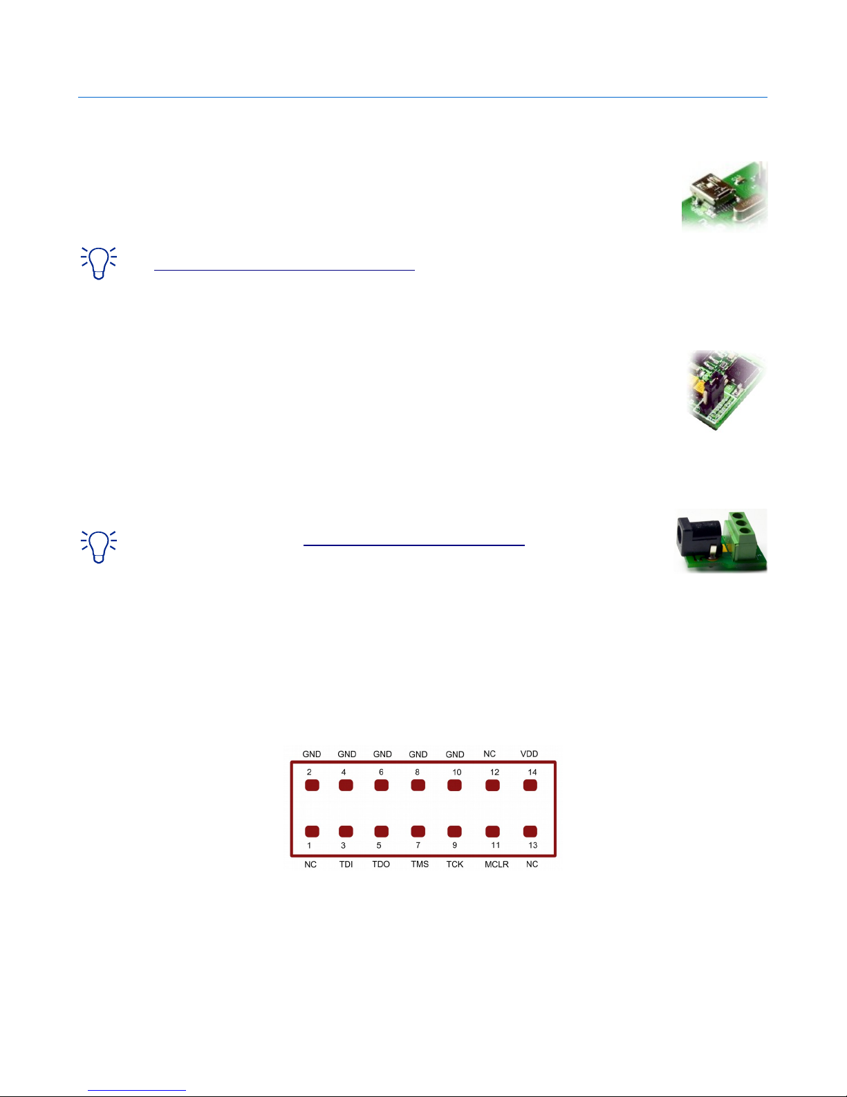
JTAG Connector
JTAG connector provides access to Microcontroller's JTAG pins. A XILINX platform cable can be used to
for JTAG programming.
©2015 NUMATO SYSTEMS PVT LTD
www.numato.com
Page 6
4 PIC32 MX Microcontroller Development Board – User Guide
GPIOs
This board is equipped with 47 GPIO pins that can be used for various custom applications. The
module has GPIO pins available on separate square pads for easy prototyping. Some of these pins can
be used as Analog to Digital Converter inputs as well. In output mode, each digital IOs can source up
to 25mA. So no additional circuitry is needed to drive regular LED's. A 470 Ohms series resistor is
recommended for current limiting when connecting LED to an IO.
In contrast to GPIOs Analog inputs can read voltages at any level between 0 to 3.3V volts. It is
recommended to use a series resistor to protect the input from stray voltages and spikes. The internal
Analog to Digital converter supports 10 bits resolution which is adequate for most applications. The
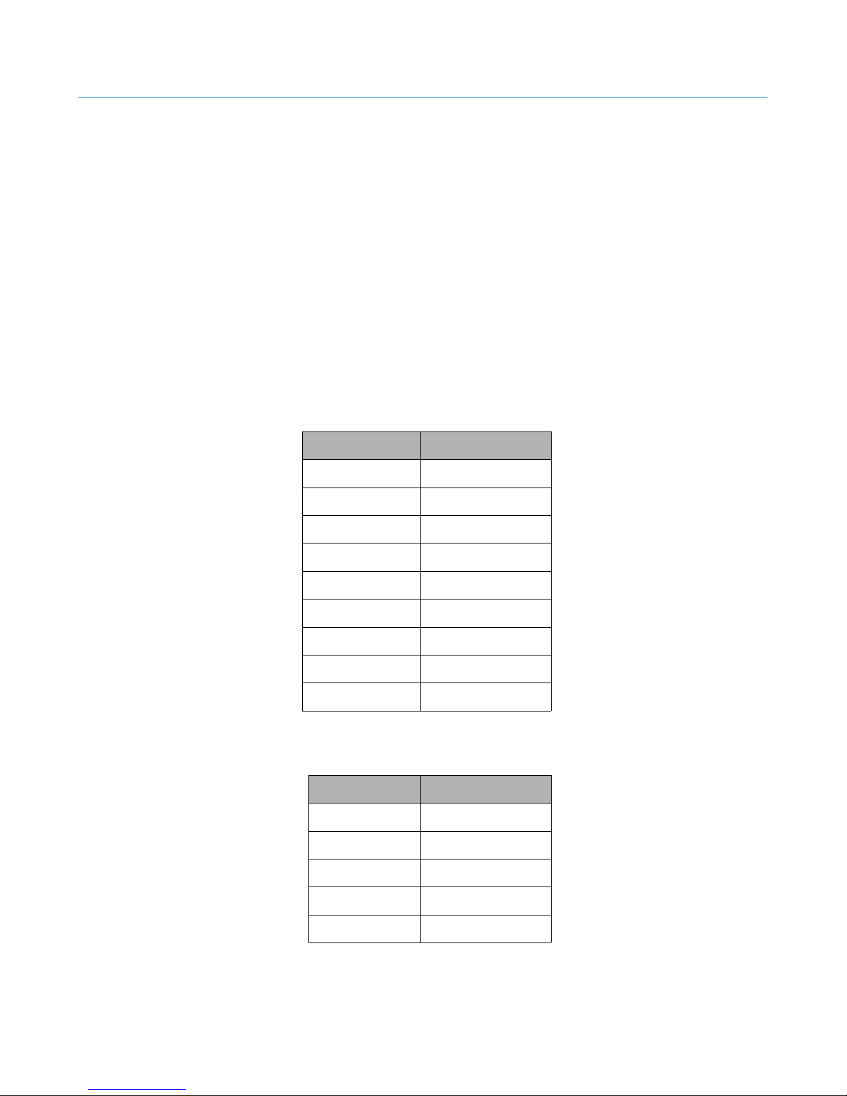
table below summarizes the GPIOs input positions on the terminals. Pin assignments on the
connectors are available in the tables below.
HEADER P1
Header pin no Pin Details
1 RG9
HEADER P2
2 RB5
3 RB4
4 RB3
5 RB2
6 RB1
7 RB0
8 PGC/RB6
9 PGD/RB7
Header pin no Pin Details
1 TDO/RB11
2 TCK/RB12
3 TDI/RB13
4 RB14
5 RB15
©2015 NUMATO SYSTEMS PVT LTD
www.numato.com
Page 7
5 PIC32 MX Microcontroller Development Board – User Guide
6 RF4
7 RF5
8 RD7
9 RF3
HEADER P5
Header pin no Pin Details
1 RG8
2 RG7
3 RG6
4 RE7
5 RE6
6 RE5
HEADER P5
7 RE4
8 RE3
9 RE2
10 RE1
11 RE0
12 RF1
13 RF0
Header pin no Pin Details
1 RD8
2 RD9
3 RD10
4 RD11
5 RD0
©2015 NUMATO SYSTEMS PVT LTD
www.numato.com
Page 8
6 PIC32 MX Microcontroller Development Board – User Guide
6 RC13
7 RC14
8 RD5
9 RD4
10 RD3
11 RD1
12 RD2
13 RD6
HEADER K2
Header pin no Pin Details
1 TMS/RB10
2 RB9
3 RB8
©2015 NUMATO SYSTEMS PVT LTD
www.numato.com
Page 9
7 PIC32 MX Microcontroller Development Board – User Guide
How to upload firmware
Most of Numato Lab's USB based products are shipped with pre-programmed bootloader to help with
field firmware updates. Please follow the steps below to update the firmware on your product.
1. Identify if your device supports field firmware upgrade
Only USB based devices support field firmware update at this time. If the device does not have
a USB connector, chances are that the device does not support field firmware update. Not all
USB based devices guaranteed to have field firmware update support either. If the device
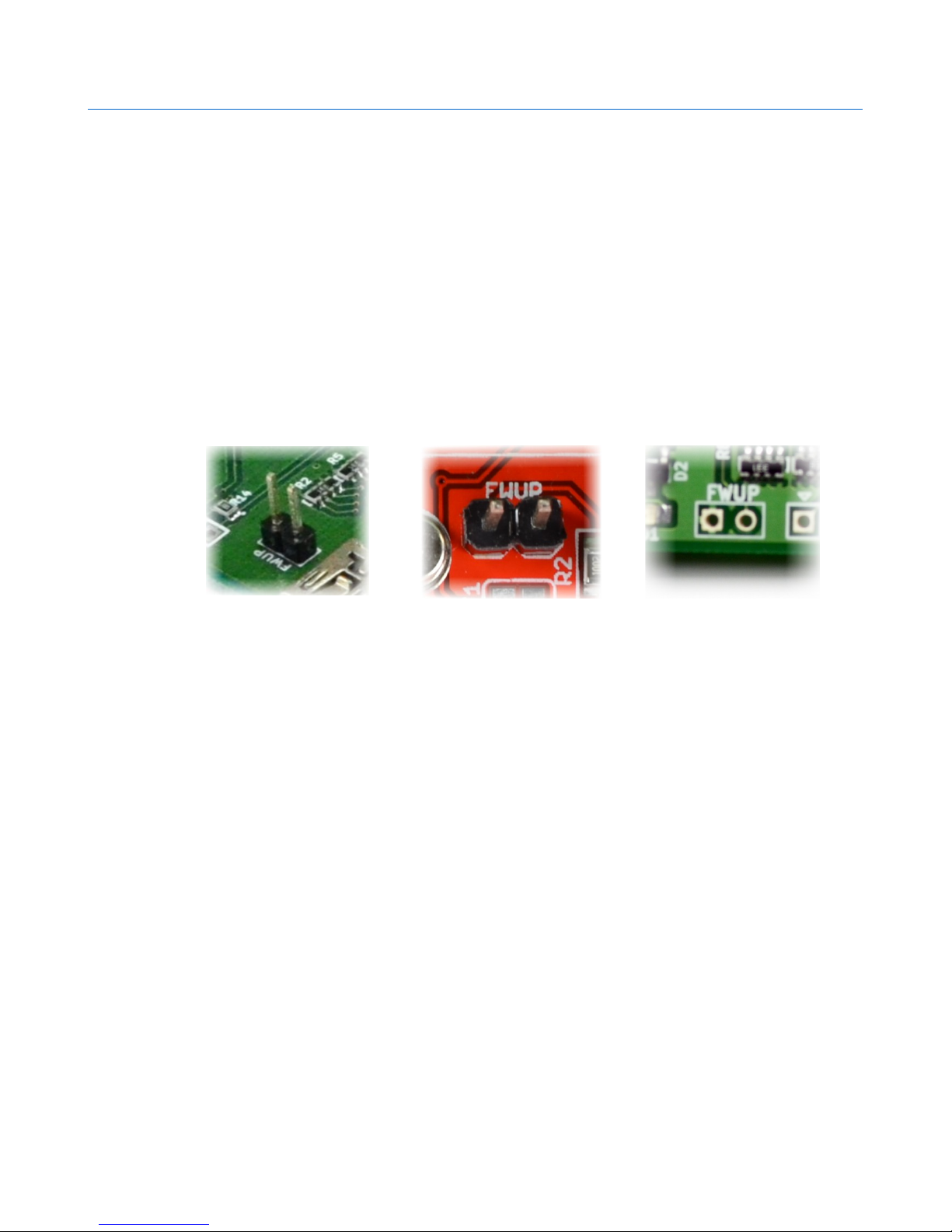
support field firmware update, there should be a two pin header or push button switch on
board with name similar to “FWUP” or “FWUPDATE”. Thoroughly inspect the board and check
if such a header is present. If there is no such jumper is present, chances are that the device
does not support field firmware update. See examples of firmware update header below.
2.
2.
2.
2.
2.
Install prerequisites
The firmware upgrade application currently supported on Windows only. It is important to
make sure that all prerequisites are installed before running the application. Following needs
to be installed before continuing with firmware upgrade.
• MS VC++ 2008 redistributable package
• MS .Net Framework 2.0
Skip this step if these packages are already installed on your machine. Installers for these two
packages are available under “prerequisites” folder in the zip package that is provided with this
document. Run the appropriate installers and follow on screen instructions to complete
installation.
3. Connecting your hardware to the PC
To activate the bootloader present on the device, press the firmware update push button
switch. Once it is short circuited, connect the device to the PC using an appropriate USB cable.
Please note that when bootloader is activated, normal features and functions will not be
accessible.
©2015 NUMATO SYSTEMS PVT LTD
www.numato.com
Page 10
8 PIC32 MX Microcontroller Development Board – User Guide
4. Downloading the firmware
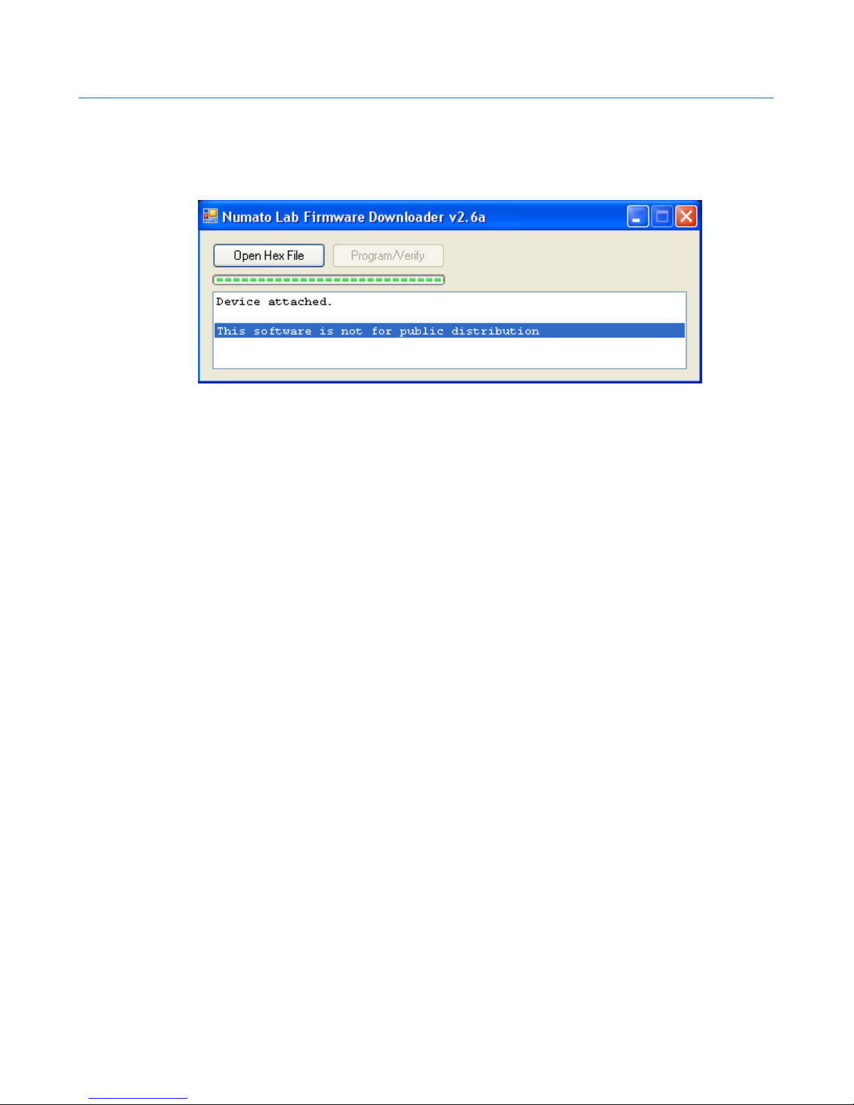
Run downloader.exe found under bin folder. If everything is setup correct, you should be
presented with the following screen.
If you are unable to run the application, please make sure that all prerequisites are installed. If
the “Open Hex File” button is grayed out, it means that the bootloader on the device is not
activated. Please make sure that the device support field firmware update and revisit step 4 to
properly connect the device to PC.
To download the firmware, click on the “Open Hex File” button, browse and select the hex file
for the product. When the hex file is selected, the “Program/Verify” button should activate.
Click the “Program/Verify” button to complete firmware download.
©2015 NUMATO SYSTEMS PVT LTD
www.numato.com
Page 11
9 PIC32 MX Microcontroller Development Board – User Guide
Technical Specifications
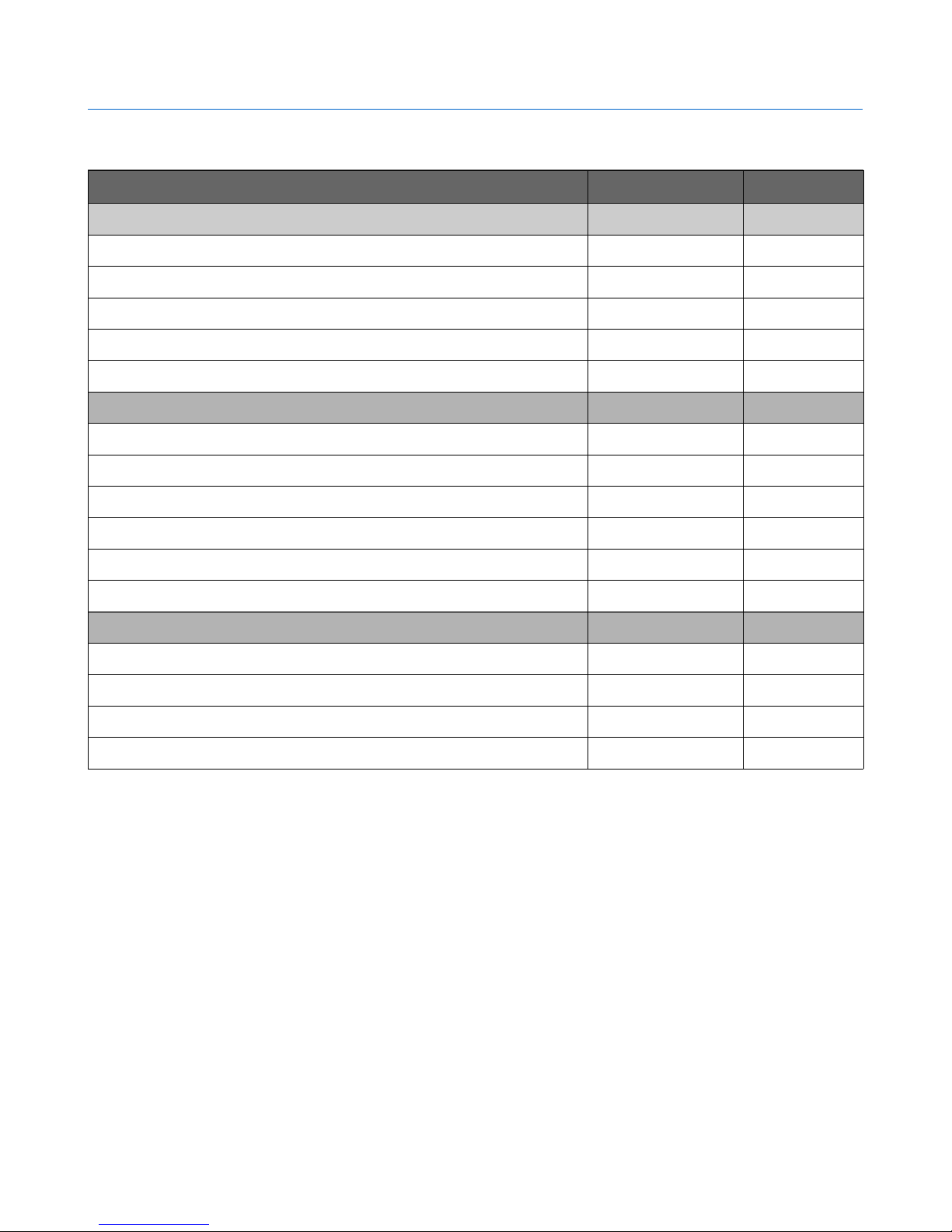
Parameter * Value Unit
Basic Specifications
Number of Digital IOs 47
Number of analog inputs 16
Digital circuit power supply voltage (External) 5 V
Digital circuit power supply voltage (USB) 5 V
Maximum current drawn by digital circuitry 250 mA
IO Specifications
Maximum IO source current 25 mA
Maximum IO sink current 25 mA
Digital IO input low voltage 0.8 V
Digital IO input high voltage 3.3 V
Digital IO output low voltage 0 V
Digital IO output high voltage 3.3 V
ADC Specifications
Resolution 10 bits
Full scale range 0 – VDD V
Reference voltage VDD V
Recommended Impedance of Analog Voltage Source 2.5 KΩ
* All parameters considered nominal. Numato Systems Pvt Ltd reserve the right to modify products without notice.
©2015 NUMATO SYSTEMS PVT LTD
www.numato.com
Page 12

10 PIC32 MX Microcontroller Development Board – User Guide
FAQ
Q. What is the connector marked as ICSP on this module?
A. This connector is used to program the on-board microcontroller. This connector is primarily intended for factory use.
Q. I need a customized version of this product, can Numato do the customization for me?
A. Yes, we can definitely do customization but there may be minimum order requirements depending on the level of
customization required. Please write to [email protected] for a quote.
Q. Where can I buy this product?
A. All Numato products can be ordered directly from our web store http://www.numato.com. We accept major credit
cards and Paypal and ship to almost all countries with a few exceptions. We do have distributors in many countries where
you can place your order. Please find the current list of distributors at http://numato.com/distrib.
©2015 NUMATO SYSTEMS PVT LTD
www.numato.com
Page 13
11 PIC32 MX Microcontroller Development Board – User Guide
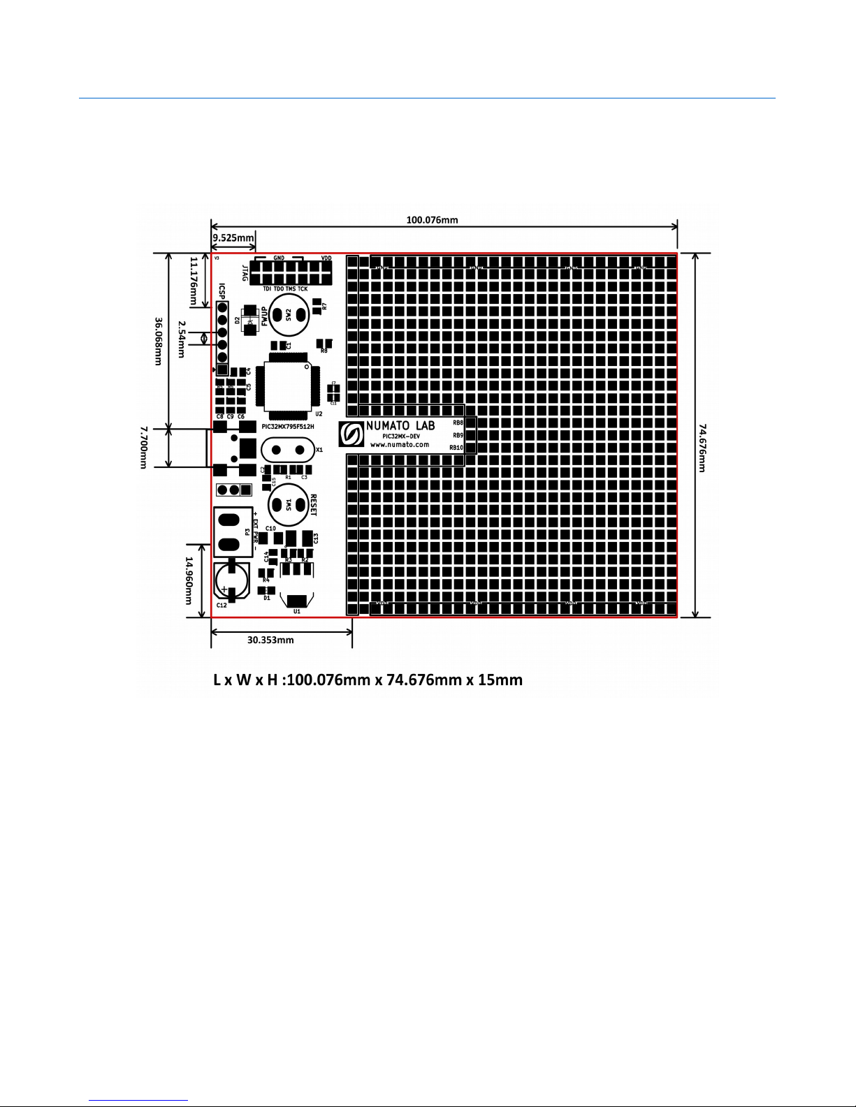
Physical Dimensions
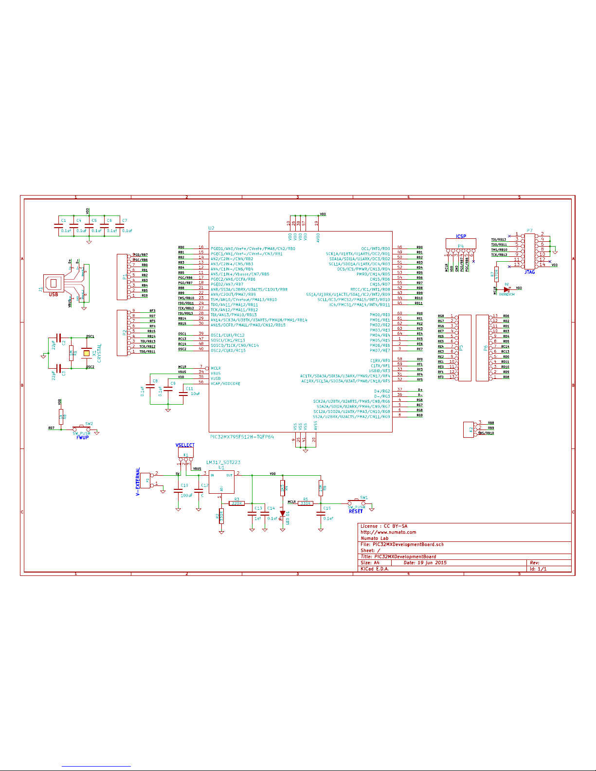
Schematics
See next page.
©2015 NUMATO SYSTEMS PVT LTD
www.numato.com
Page 14
1
1
2
2
3
3
4
4
5
5
A A
B B
C C
Date: 19 jun 2015
KiCad E.D.A.
Rev: Size: A4
Id: 1/1
Title: PIC32MXDevelopmentBoard
File: PIC32MXDevelopmentBoard.sch
Sheet: /
Numato Lab
http://www.numato.com
License : CC BY-SA
RD7
C10
100uF
VDD
SW1
SW_PUSH
SW2
SW_PUSH
R8
1k
VDD
D2
DIODESCH
VDD
1
2
P3
V-EXTERNAL
C12
C
RESET
VBUS
5V
123
K1
TMS/RB10
RB9
RB8
1
2
3
K2
RD8
RF5
RF4
RF3
RB15
RB14
TDI/RB13
TCK/RB12
TD0/RB11
PGD/RB7
PGC/RB6
RG9
RB5
RB4
RB3
RB2
RB1
RB0
1
2
3
4
5
6
7
8
9
P2
1
2
3
4
5
6
7
8
9
P1
RG8
RG7
RG6
RF1
RF0
RE7
RE6
RE5
RE4
RE3
RE2
RE1
RE0
1
2
3
4
5
6
7
8
9
10
11
12
13
P5
RD7 RD6
RD5
RD4
RD3
RD2
RD1
RD0
RC14
RC13
RD11
RD10
RD9
1
2
3
4
5
6
7
8
9
10
11
12
13
P6
RG6
RG7
RG8
RG9
RF5
RF4
RF3
RF1
RF0
RE7
RE6
RE5
RE4
RE3
RE2
RE1
RE0
RD11
RD10
RD9
RD8
RD7
RD6
RD5
RD4
RD3
RD2
RD1
RD0
RC14
RC13
TDI/RB13
TCK/RB12
RB15
RB14
TD0/RB11
TMS/RB10
RB9
RB8
PGD/RB7
PGC/RB6
RB5
RB4
RB3
RB2
RB1
RB0
X1
CRYSTAL
R1
1M
VDD
JTAG
C11
10uf
C9
0.1uf
C8
0.1uf
MCLR
R5
330R
C15
0.1uf
R6
10K
12
D1LED
R4
1K5
C14
0.1uf
C13
1uf
R2
330R
R3
220R
ADJ
1
OUT
2
IN
3
U1
LM317_SOT223
MCLR
R7
470R
VDD
1 2
3 4
5 6
7 8
9 10
11 12
13 14
P7
GND
VDD
MCLR
ICSP
12345
6
P4
D-
D+VBUS
USB
Vbus
1
D-
2D+3
GND
4
Shield_1
5
Shield_2
6
J1
D-
D+
C1
0.1uf
VDD
C7
0.1uf
C6
0.1uf
C4
0.1ufC50.1uf
OSC2
OSC1
C3
22pF
C2
22pF
TDI/RB13
TCK/RB12
TD0/RB11
TMS/RB10
PGD/RB7
PGC/RB6
VBUS
MCLR
OSC2
OSC1
VDD
PMD5/RE5
1
PMD6/RE6
2
PMD7/RE7
3
SCK2A/U2BTX/U2ARTS/PMA5/CN8/RG6
4
SDA2A/SDI2A/U2ARX/PMA4/CN9/RG7
5
SCL2A/SDO2A/U2ATX/PMA3/CN10/RG8
6
MCLR
7
SS2A/U2BRX/U2ACTS/PMA2/CN11/RG9
8
VSS
9
VDD
10
AVSS
20
AN15/OCFB/PMALL/PMA0/CN12/RB15
30
OSC2/CLK0/RC15
40
SDA1A/SDI1A/U1ARX/OC3/RD2
50
PMD0/RE0
60
AN5/C1IN+/Vbuson/CN7/RB5
11
AN8/SS3A/U3BRX/U3ACTS/C1OUT/RB8
21
AC1TX/SDA3A/SDI3A/U3ARX/PMA9/CN17/RF4
31
VSS
41
SCL1A/SDO1A/U1ATX/OC4/RD3
51
PMD1/RE1
61
AN4/C1IN-/CN6/RB4
12
AN9/C2OUT/PMA7/RB9
22
AC1RX/SCL3A/SDO3A/U3AT/PMA8/CN18/RF5
32
RTCC/IC1/INT1/RD8
42
OC5/IC5/PMWR/CN13/RD4
52
PMD2/RE2
62
AN3/C2IN+/CN5/RB3
13
TSM/AN10/CVrefout/PMA13/RB10
23
USBID/RF3
33
SS1A/U1BRX/U1ACTS/SDA1/IC2/INT2/RD9
43
PMRD/CN14/RD5
53
PMD3/RE3
63
AN2/C2IN-/CN4/RB2
14
TDO/AN11/PMA12/RB11
24
VBUS
34
SCL1/IC3/PMCS2/PMA15/INT3/RD10
44
CN15/RD6
54
PMD4/RE4
64
PGEC1/AN1/Vref-/CVref-/CN3/RB1
15
VSS
25
VUSB
35
IC4/PMCS1/PMA14/INT4/RD11
45
CN16/RD7
55
PGED1/AN0/Vref+/CVref+/PMA6/CN2/RB0
16
VDD
26
D-/RG3
36
OC1/INT0/RD0
46
VCAP/VDDCORE
56
PGEC2/AN6/OCFA/RB6
17
TCK/AN12/PMA11/RB12
27
D+/RG2
37
SOSCI/CN1/RC13
47
VDD
57
PGED2/AN7/RB7
18
TDI/AN13/PMA10/RB13
28
VDD
38
SOSCO/T1CK/CN0/RC14
48
C1RX/RF0
58
AVDD
19
AN14/SCK3A/U3BTX/U3ARTS/PMALH/PMA1/RB14
29
OSC1/CLKI/RC12
39
SCK1A/U1BTX/U1ARTS/OC2/RD1
49
C1TX/RF1
59
U2
PIC32MX795F512H-TQFP64
VSELECT
FWUP
 Loading...