

Page 1
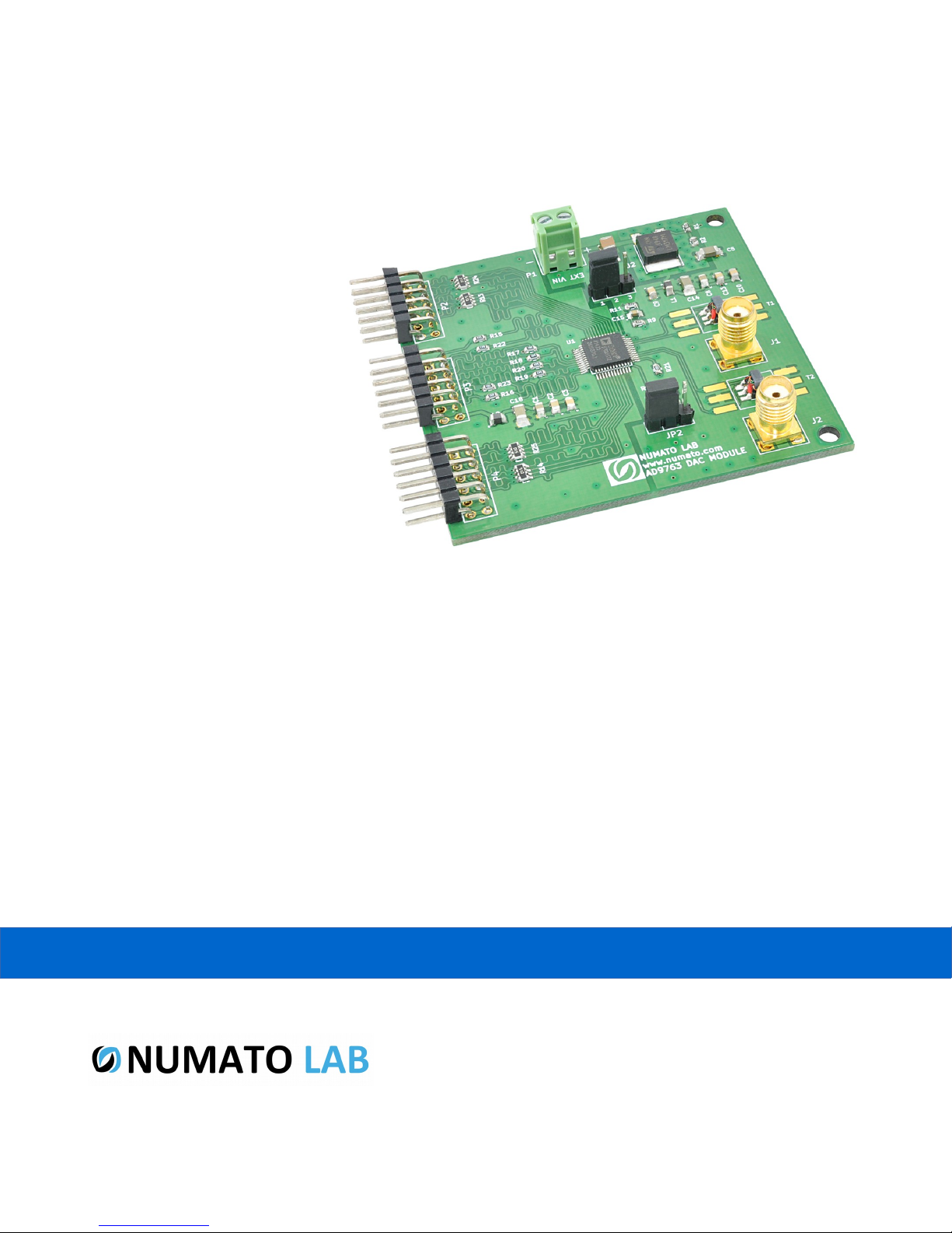
AD9763 DAC Expansion Module
User Guide
www.numato.com
Rev 9
Page 2

Get in touch with us!
Please feel free to send a mail to one of the mail IDs below or use the Contact Us page at
http://www.numato.com to drop us a quick message.
Technical Help
Got technical questions? Please write to [email protected]
Sales Team
Questions about making payments, volume discounts, academic/open source discounts, purchase
orders and quotes? Please write to [email protected]
Webmaster
Questions/Suggestions about our website? Please write to [email protected]
Like us on Facebook! https://www.facebook.com/numato
Visit our blog http://www.numato.cc for news, updates and specials.
Mailing Address
Numato Systems Pvt Ltd
1st Floor, #56C Wipro Avenue
Phase 1 - Electronic City
Bangalore, KA-560100, India
* Mail orders, phone orders and direct pick up are not available at this time. Please visit our online store to place your order. Estimated shipping time to
your address will be displayed in the shopping cart before checkout.
You may use, modify or share this publication or part of thereof adhering to Creative
Commons Attribution-ShareAlike 3.0 Unported (CC BY-SA 3.0) License.
See complete license text at http://creativecommons.org/licenses/by-sa/3.0/
All trademarks are property of their respective owners.
Page 3

1 AD9763 DAC Expansion Module – User Guide
Introduction
The AD9763 DAC module features AD9763, a dual-port, high speed, 2-channel, 10-bit CMOS Digital to
Analog converter. The AD9763 offer exceptional ac and dc performance while supporting update rates
of up to 125 MSPS. This module is designed to be used with Numato Lab’s FPGA/Micro-controller
boards featuring a 2×6 pin Expansion connector. It can also be used with other boards and connector
types by using manual wiring.
Applications
• Quadrature Modulation
• Data acquisition
• Digital Synthesis
Board features
• Three 2×6 expansion connectors
• 10-Bit dual transmit DAC
• 125 MSPS update rate
• Dual-port or interleaved data
• Power dissipation: 380 mW @ 5 V
• Dimension: 64mm x 62mm
©2015 NUMATO SYSTEMS PVT LTD
www.numato.com
Page 4
2 AD9763 DAC Expansion Module – User Guide
How to use the module
The following section describes how to use this module.
Components/Tools required
Along with the module, you may need the items in the list below for easy and fast installation.
1. Any FPGA/Micro-controller board featuring a 2×6 pin Expansion connector (Manual wiring may
be needed if using with boards that does not have 2×6 expansion connector)
2. DC Power supply (5-7)V.
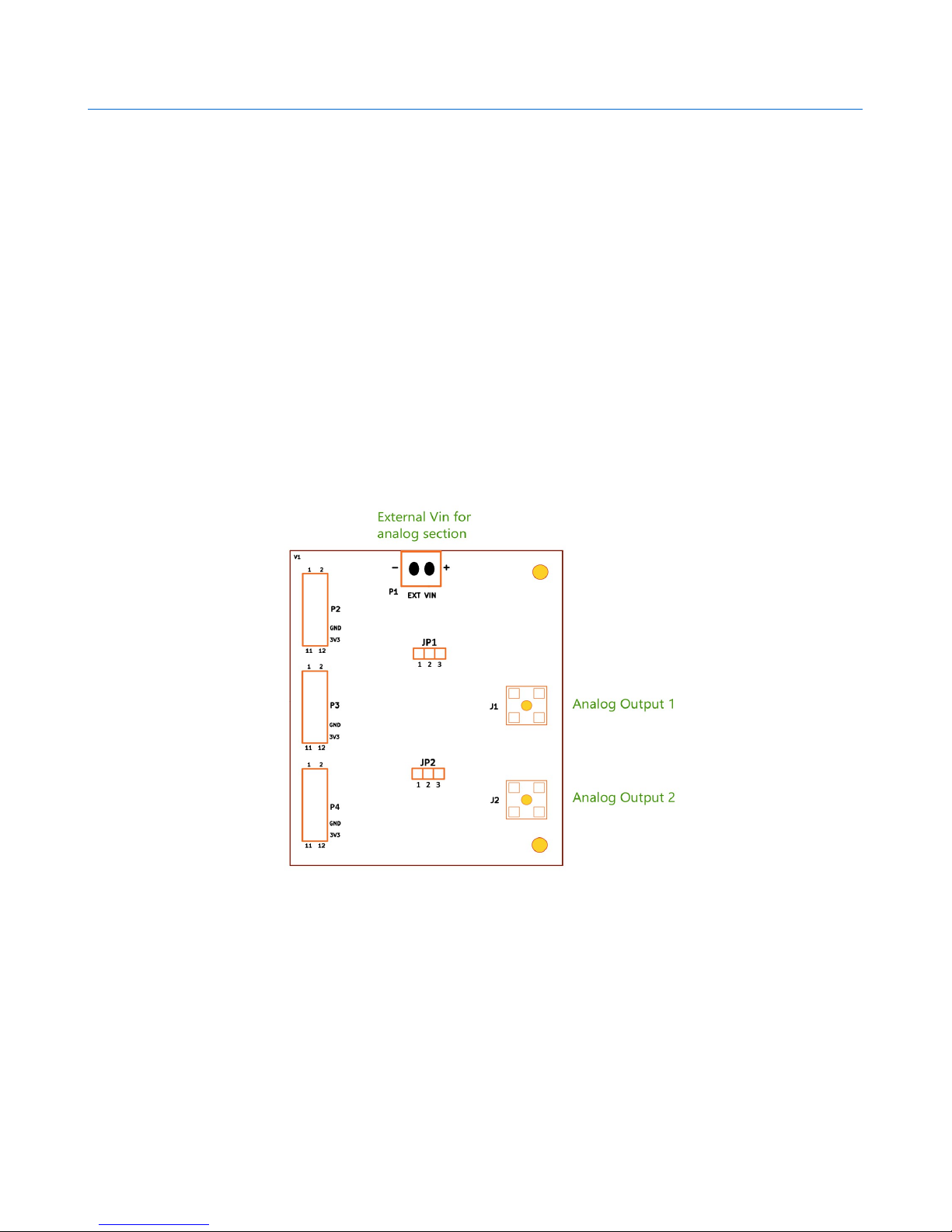
Connection Diagram
This diagram should be used as a reference only. For detailed information, see the schematics at the
end of this document. Details of individual connectors are as below.
To use this module, directly attach the 2×6 male header on the expansion module to the 2×6
expansion connector on FPGA/Micro-controller development board. If 2×6 female headers are not
available, manually make the connections as per the connection details below.
©2015 NUMATO SYSTEMS PVT LTD
www.numato.com
Page 5
3 AD9763 DAC Expansion Module – User Guide
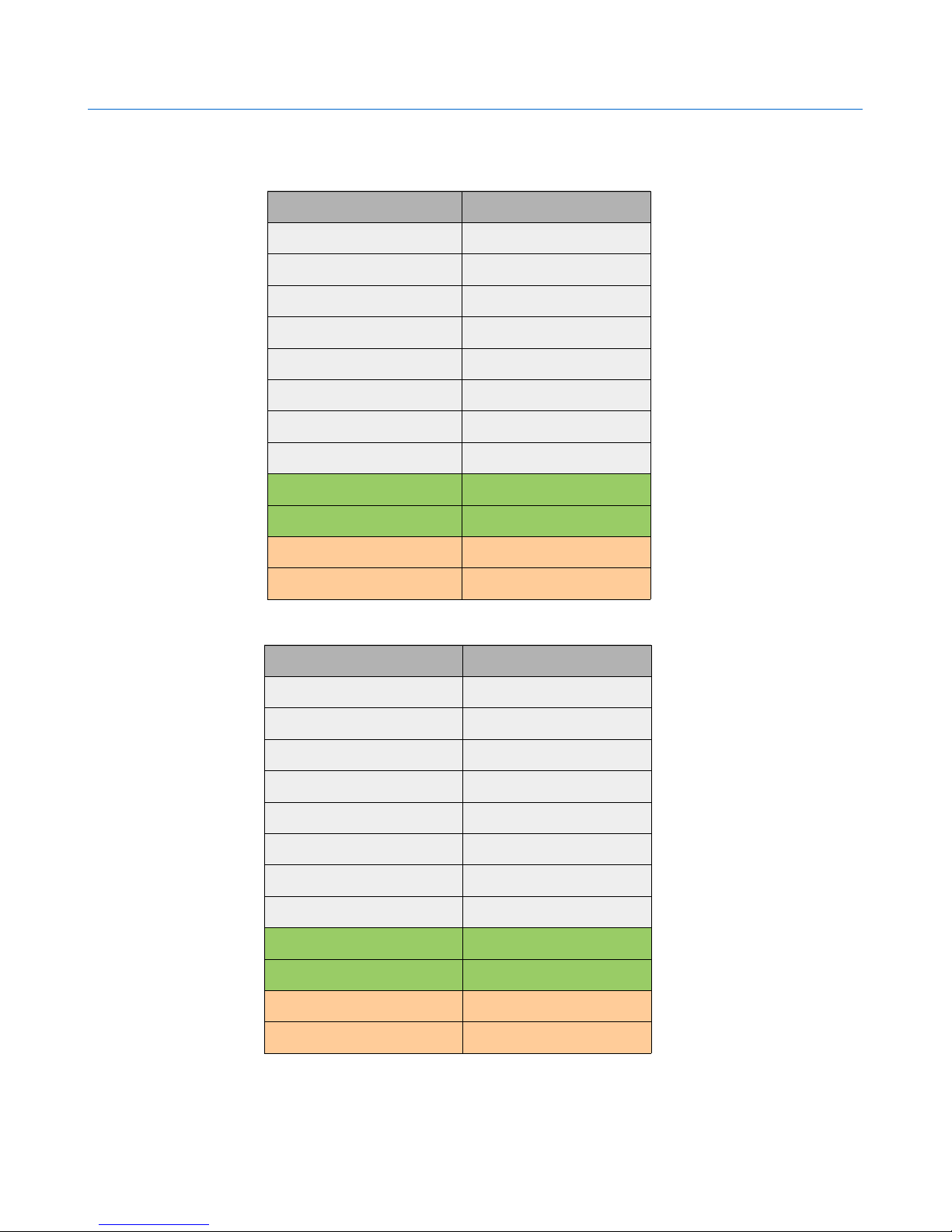
Connection Details
Header P2
Header Pin No. Pin Details
1 INP8
2 INP9
3 INP6
4 INP7
5 INP4
6 INP5
7 INP2
8 INP3
9 DGND
10 DGND
Header P3
11 VDD
12 VDD
Header Pin No. Pin Details
1 INP1
2 INP0
3 CLK2
4 CLK1
5 WRT1
6 WRT2
7 INP18
8 INP19
9 DGND
10 DGND
11 VDD
12 VDD
©2015 NUMATO SYSTEMS PVT LTD
www.numato.com
Page 6
4 AD9763 DAC Expansion Module – User Guide
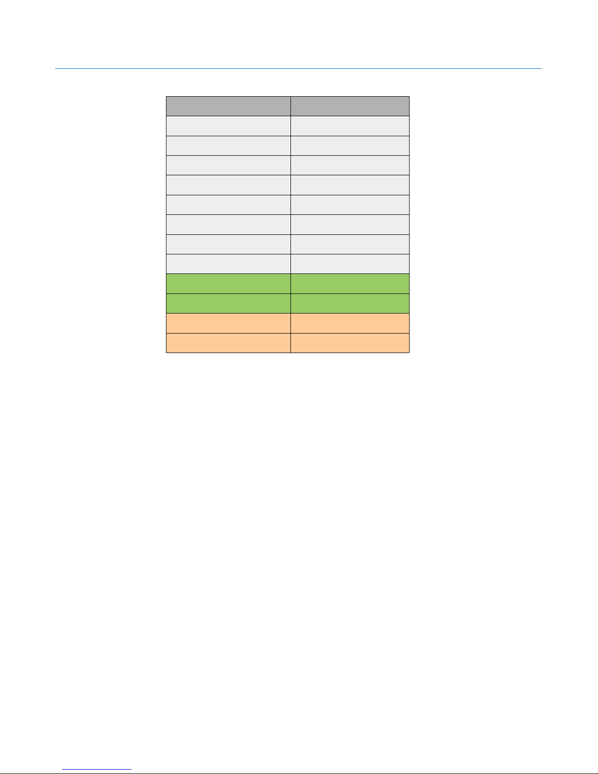
Header P4
Header Pin No. Pin Details
1 INP16
2 INP17
3 INP14
4 INP15
5 INP12
6 INP13
7 INP10
8 INP11
9 DGND
10 DGND
11 VDD
12 VDD
For more information, refer the schematics at the end of this document.
Jumper Selection
Jumper P1
Enables you to choose the modes of DAC, i.e. dual port and interleaved mode. Place the jumper in
position 1-2 to select dual port mode and position 2-3 to select interleaved mode.
Jumper P2
Enables you to choose the Gain control modes of DAC, i.e. independent and master/slave mode. Place
the jumper in position 1-2 to select master/slave mode and position 2-3 to select independent mode.
©2015 NUMATO SYSTEMS PVT LTD
www.numato.com
Page 7
5 AD9763 DAC Expansion Module – User Guide
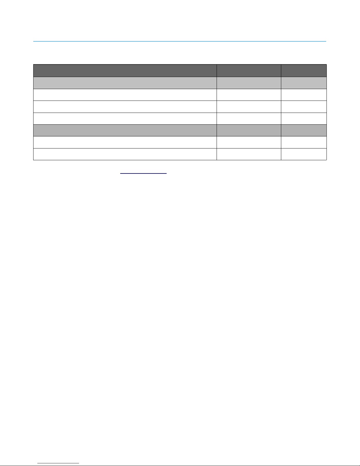
Technical Specifications
Parameter * Value Unit
Basic Specifications
Conversion resolution 10 Bits
Max Sample rate 125 MSPS
SFDR to Nyquist 75 dB @ 5MHz
External Power Supply 5-7 V
DC Power Supply (VD) 3.3 V
Digital Input Voltage
* All parameters considered nominal. Numato Systems Pvt Ltd reserve the right to modify products without notice.
For more information refer AD9763 Data Sheet
-0.3 to DVDD + 0.3
V
©2015 NUMATO SYSTEMS PVT LTD
www.numato.com
Page 8
6 AD9763 DAC Expansion Module – User Guide
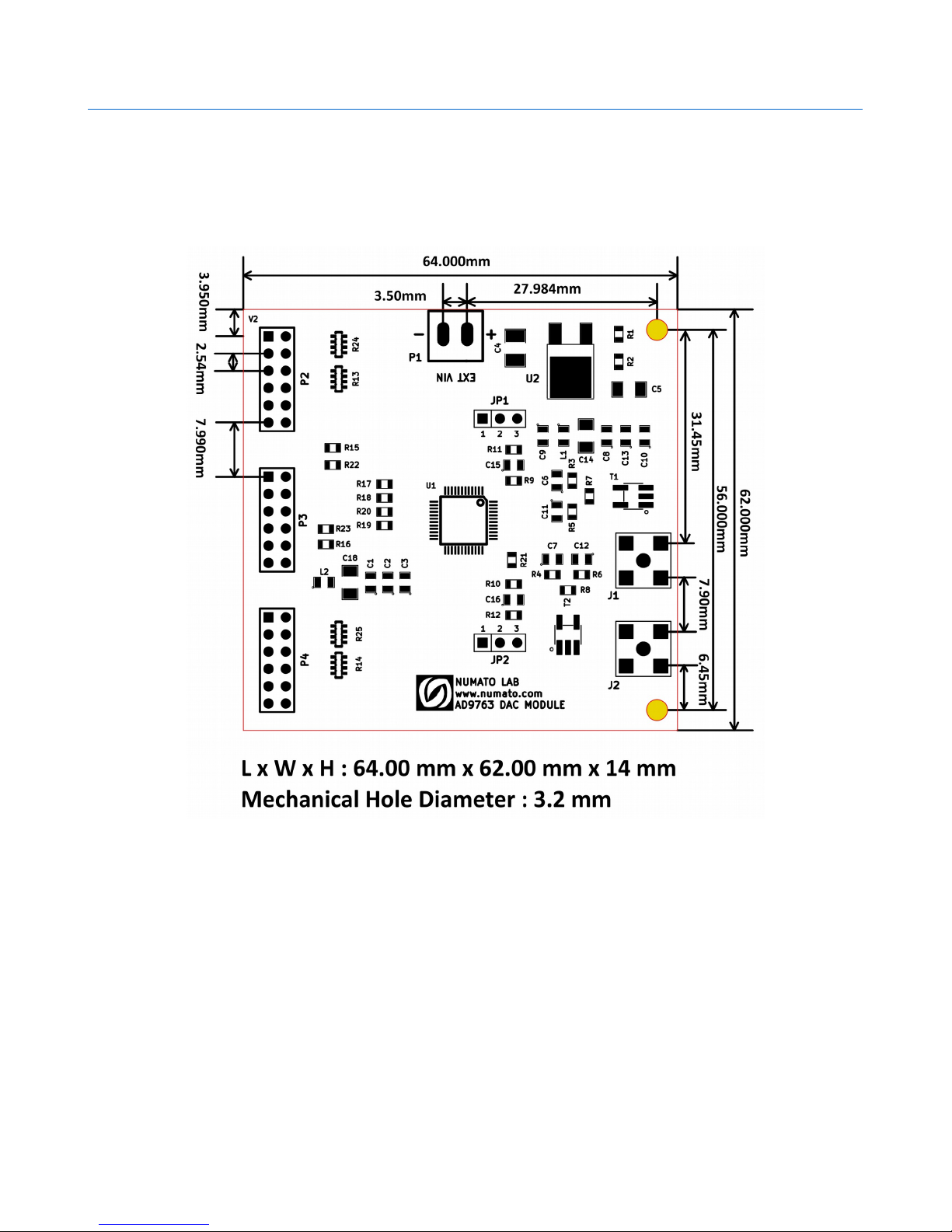
Physical Dimensions
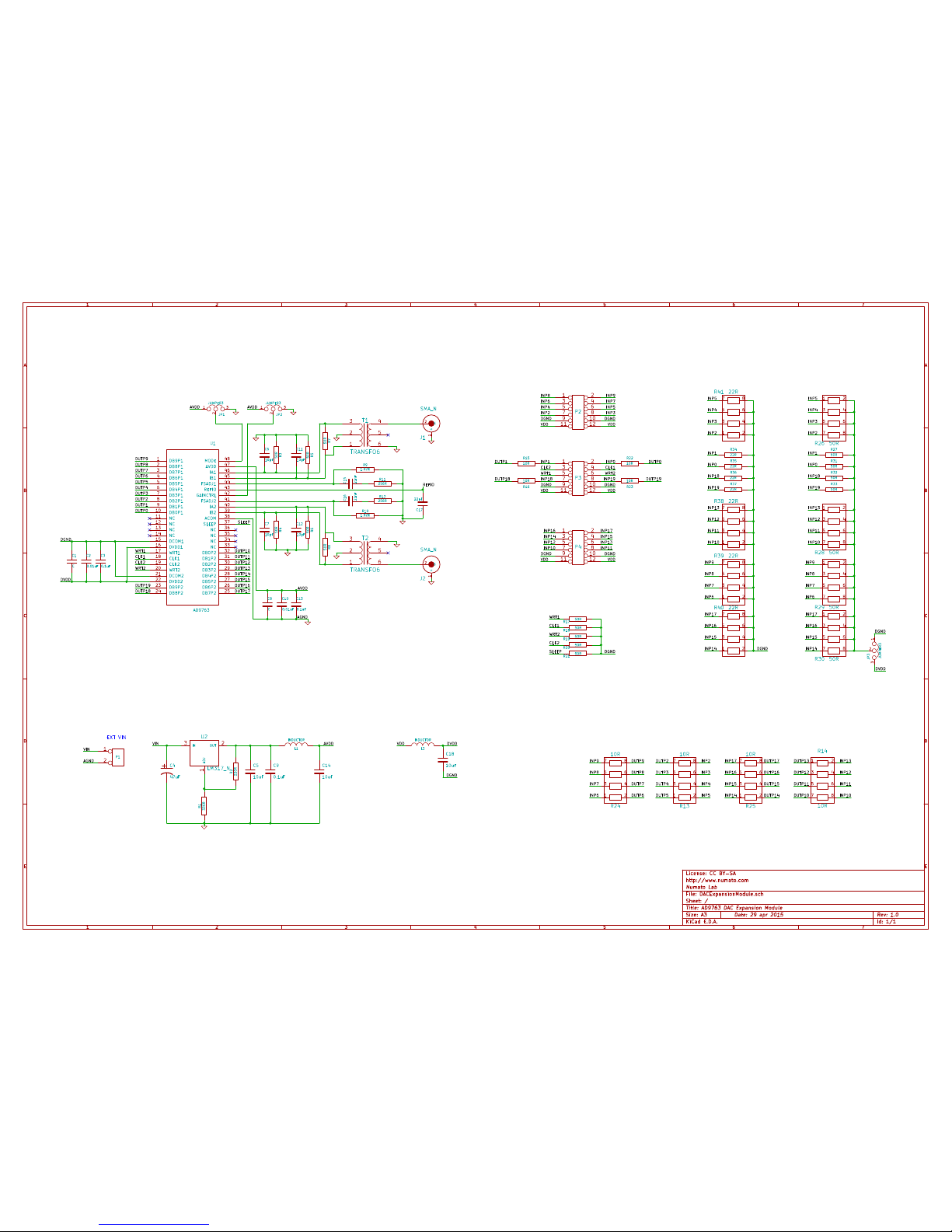
Schematics
See next page.
©2015 NUMATO SYSTEMS PVT LTD
www.numato.com
Page 9
1
1
2
2
3
3
4
4
5
5
6
6
7
7
A A
B B
C C
D D
E E
Date: 29 apr 2015
KiCad E.D.A.
Rev: 1.0Size: A3
Id: 1/1
Title: AD9763 DAC Expansion Module
File: DACExpansionModule.sch
Sheet: /
Numato Lab
http://www.numato.com
License: CC BY-SA
1 2
3 4
5 6
7 8
9 10
11 12
P2
DGNDDGND
1
2
P1
VIN
EXT VIN
1 2
3 4
5 6
7 8
9 10
11 12
P3
DGND
VDD
VDDVDD
VDD
C9
0.1uFC510uF
R1
330R
R2
220R
+
C4
47uF
G
1
S
2
J1
SMA_N
VIN
ADJ
1
OUT2IN
3
U2
LM317_N
DUTP1
DUTP2
DUTP3
DUTP4
DUTP5
DUTP6
DUTP7
DUTP8
DUTP9
DUTP0
SLEEP
C1CC2
0.01uFC30.1uF
C6
10pF
C11
10pF
R3
50RR550R
123
JP1
JUMPER3
AVDD
C15
22nF
R11
256R
R9
1.92K
123
JP2
JUMPER3
AVDD
DUTP10
DUTP11
DUTP12
DUTP13
DUTP14
DUTP15
DUTP16
DUTP17DUTP18
DUTP19
C7
10pF
C12
10pF
R4
50RR650R
C16
22nF
R12
256R
R10
1.92K
C17
22nF
AVDD
1
2
3 4
5
6
T1
TRANSFO6
G
1
S
2
J2
SMA_N
1
2
3 4
5
6
T2
TRANSFO6
WRT1
CLK1
CLK2
WRT2
DVDD
C8CC10
0.01uF
C13
0.1uF
DB9P1
1
DB8P1
2
DB7P1
3
DB6P1
4
DB5P1
5
DB4P1
6
DB3P1
7
DB2P1
8
DB1P1
9
DB0P1
10
WRT2
20
DB2P2
30
IA2
40
NC
11
DCOM2
21
DB1P2
31
FSADJ2
41
NC
12
DVDD2
22
DB0P2
32
GAINCTRL
42
NC
13
DB9P2
23
NC
33
REFIO
43
NC
14
DB8P2
24
NC
34
FSADJ1
44
DCOM1
15
DB7P2
25
NC
35
IB1
45
DVDD1
16
DB6P2
26
NC
36
IA1
46
WRT1
17
DB5P2
27
SLEEP
37
AVDD
47
CLK1
18
DB4P2
28
ACOM
38
MODE
48
CLK2
19
DB3P2
29
IB2
39
U1
AD9763
DUTP1
DUTP2
DUTP3
DUTP4
DUTP5DUTP6
DUTP7
DUTP8
DUTP9
DUTP0
DUTP10
DUTP11
DUTP12
DUTP13
DUTP14
DUTP15
DUTP16
DUTP17
DGND
VDD
VDD
REFIO
1 2
3 4
5 6
7 8
9 10
11 12
P4
WRT1
CLK1CLK2
WRT2
R8
50R
R7
50R
DGND
DGND
DGND
AGND
AGND
L2
INDUCTOR
L1
INDUCTOR
C14
10uF
AVDD VDD
C18
10uF
DGND
1 2
3 4
5 6
7 8
R13
10R
1 2
3 4
5 6
7 8
R24
10R
1 2
3 4
5 6
7 8
R14
10R
1 2
3 4
5 6
7 8
R25
10R
R15
10R
R16
10R
DVDD
INP0INP1
INP2 INP3
INP4 INP5
INP6 INP7
INP8 INP9
INP10 INP11
INP12 INP13
INP14 INP15
INP16 INP17
1 2
3 4
5 6
7 8
R26 50R
1 2
3 4
5 6
7 8
R28 50R
1 2
3 4
5 6
7 8
R29 50R
INP0
INP2
INP4
INP6
INP1
INP3
INP5
INP7
INP8
INP10
INP12
INP14
INP9
INP11
INP13
INP15
INP16
INP17
DGND
1
2
3
JP3
JUMPER3
DVDD
WRT1
CLK1
CLK2
WRT2
SLEEP
R17
50R
R18
50R
R19
50R
R20
50R
R21
50R
DGND
DUTP19DUTP18
R22
10R
R23
10R
INP19INP18
1 2
3 4
5 6
7 8
R30 50R
INP18
INP19
INP13
INP12
INP11
INP10
INP17
INP16
INP15
INP14
INP2
INP3
INP4
INP5
INP9
INP8
INP7
INP6
R27
50R
R31
50R
R32
50R
R33
50R
1 2
3 4
5 6
7 8
R41 22R
1 2
3 4
5 6
7 8
R38 22R
1 2
3 4
5 6
7 8
R39 22R
INP0
INP2
INP4
INP6
INP1
INP3
INP5
INP7
INP8
INP10
INP12
INP14
INP9
INP11
INP13
INP15
INP16
INP17
DGND1 2
3 4
5 6
7 8
R40 22R
INP18
INP19
R34
22R
R35
22R
R36
22R
R37
22R
 Loading...