

Page 1

G3Series
TM
EtherNet/IP
TechnicalManual
TDG3DNTM1-1EN 05/09
Subject to change without notice
www.numatics.com/g3
Page 2

G3SeriesEtherNet/IPTechnicalManual
Table of Contents
PAGE
About EtherNet/IP ................................................................................................................................................................ 3
Overview ............................................................................................................................................................................ 3
G3 EtherNet/IP
G3 Introduction ...................................................................................................................................................................... 4
G3 Electronics Modularity ................................................................................................................................................. 5
Discrete I/O .................................................................................................................................................................. 5
Pneumatic Valve Manifold ............................................................................................................................................ 6
Manifold Connectors ......................................................................................................................................................... 7
Solenoid Coil Connections using Z-Board
Z-Board™ Connectors .................................................................................................................................................. 8
Z-Board™ and Ribbon Cable Example ....................................................................................................................... 9
Z-Board™ with Valve Side Sub-D Example .............................................................................................................. 10
Communication Module ....................................................................................................................................................... 11
EtherNet/IP Communication Module (Node) ............................................................................................................... 11
Communication Module Description ............................................................................................................................. 12
Connector Pin-Outs ......................................................................................................................................................... 13
Electrical Connections ..................................................................................................................................................... 14
Power Connector Wiring Diagram ............................................................................................................................. 14
EtherNet/IP
EtherNet/IP
Power Consumption ........................................................................................................................................................ 17
External Fuse Sizing Chart ......................................................................................................................................... 18
Diagnostics ...................................................................................................................................................................... 19
Communication Module LED Functions .................................................................................................................. 19
Output Short Circuit Protection ................................................................................................................................. 20
G3 Graphic Display .............................................................................................................................................................. 21
IP Address Sub-Menu ...................................................................................................................................................... 22
Subnet Mask Sub-Menu .................................................................................................................................................. 23
DHCP-BOOTP Sub-Menu ............................................................................................................................................. 24
MAC ADDR Menu .......................................................................................................................................................... 25
Advanced Settings - I/O Diag. Menu ............................................................................................................................. 26
Advanced Settings - Diagnostic Word ............................................................................................................................ 27
Advanced Settings - Fault Action .................................................................................................................................... 28
Advanced Settings - Idle Action ...................................................................................................................................... 29
Advanced Settings - Brightness ....................................................................................................................................... 30
Factory Defaults ............................................................................................................................................................... 31
Diagnostics - Self Test Mode .......................................................................................................................................... 32
Diagnostics Cont. ............................................................................................................................................................ 33
Error Messages ................................................................................................................................................................ 34
MCM – Manual Configuration Module (Optional) ............................................................................................................. 35
DIP Switch Settings ......................................................................................................................................................... 36
ARM – Auto Recovery Module (Optional) .......................................................................................................................... 37
Distribution .......................................................................................................................................................................... 38
Sub-Bus Distribution Modules ........................................................................................................................................ 39
Sub-Bus OUT Module ................................................................................................................................................ 39
Sub-Bus Valve Module ................................................................................................................................................ 42
Digital I/O Modules ............................................................................................................................................................ 42
Digital I/O Module Rules ............................................................................................................................................... 43
I/O Module Descriptions and Menus ............................................................................................................................ 44
Menu ................................................................................................................................................................................ 44
Digital Input Modules ..................................................................................................................................................... 45
One Digital Input per Connector – M12 Female Modules ........................................................................................ 45
Two Digital Inputs per Connector – M12 Female Modules ...................................................................................... 46
TM
Features.............................................................................................................................................. 3
™
technology ............................................................................................. 7
TM
Straight-Through Cabling Diagrams ............................................................................................... 15
TM
Crossover Cabling Diagrams ........................................................................................................... 16
TDG3EPTM1-1EN 05/09
Subject to change without notice
Page 1
www.numatics.com/g3
Page 3

G3SeriesEtherNet/IPTechnicalManual
Sixteen Digital Inputs – Terminal Strip Modules ...................................................................................................... 47
Digital Output Modules .................................................................................................................................................. 48
One Digital Output per Connector - M12 Female Modules ...................................................................................... 48
Two Digital Outputs per Connector - M12 Female Modules .................................................................................... 49
Sub-Bus Valve Module ................................................................................................................................................ 50
Digital Input/Output Modules ....................................................................................................................................... 51
Two Digital I/O per Connector - 12mm Female Modules ........................................................................................ 51
Valve Side Digital Output Modules ................................................................................................................................ 52
Sixteen Outputs per Connector - Sub-D 25 Pin Female Module ............................................................................... 52
Analog I/O Modules ............................................................................................................................................................ 53
Analog I/O Module Rules ............................................................................................................................................... 53
Four I/O - 12mm Female Modules ............................................................................................................................ 53
One Analog Input per Connector – M12 Female Modules ........................................................................................ 54
One Analog I/O per Connector – M12 Female Modules .......................................................................................... 55
I/O Module(s) Wiring Diagrams ........................................................................................................................................ 56
EtherNet/IP
TM
Configuration and Mapping ...................................................................................................................... 58
EDS File ........................................................................................................................................................................... 58
Connecting to a G3 Series EtherNet/IP
Using the Functionality of the G3 Series EtherNet/IP
TM
Node ........................................................................................................... 59
TM
Web Server .......................................................................... 63
Home ........................................................................................................................................................................... 63
Node Configuration .................................................................................................................................................... 64
I/O Force and Test ..................................................................................................................................................... 65
Diagnostics .................................................................................................................................................................. 66
Numatics.com ............................................................................................................................................................. 66
IP Address Configuration ................................................................................................................................................ 67
DHCP / BOOTP ........................................................................................................................................................ 67
Integrated Web Page Configuration ........................................................................................................................... 68
Configuration with RSLogix 5000 ................................................................................................................................... 70
Module Properties ....................................................................................................................................................... 70
User Configurable Device Parameters ............................................................................................................................ 71
Communication Fault/Idle Mode Parameter ................................................................................................................. 72
Communication Fault / Idle Mode Sequence ........................................................................................................... 72
EtherNet/IP
TM
Mapping ..................................................................................................................................................... 73
I/O Sizes .......................................................................................................................................................................... 73
Manifold and I/O Data Sizing Worksheet...................................................................................................................... 74
Discrete I/O Side ........................................................................................................................................................ 75
Appendix ............................................................................................................................................................................... 86
System Specifications ...................................................................................................................................................... 86
Factory Default Settings .................................................................................................................................................. 87
Troubleshooting .............................................................................................................................................................. 88
Glossary of Terms ............................................................................................................................................................ 89
Technical Support ............................................................................................................................................................ 91
TDG3EPTM1-1EN 05/09
Subject to change without notice
Page 2
www.numatics.com/g3
Page 4

G3SeriesEtherNet/IPTechnicalManual
About EtherNet/IP
Overview
EtherNet/IPTM is a communication protocol that uses the same network technology that can be found in
commercial and domestic operations worldwide, but has added benefits/features toward manufacturing
applications. It is a CIP (common industrial protocol) Network that follows the Open Systems
Interconnection (OSI) model.
The ODVA (Open DeviceNet Vendor Association) is an independent organization that governs the
EtherNet/IP
EtherNet/IP
speeds of 10 Mbps and 100 Mbps. Maximum network cabling distance is limited to 100m segments at 20º C.
More information about EtherNet/IP
G3 EtherNet/IPTM Features
TM
specification and oversees conformance testing for products.
TM
uses industrial M12 IP67-rated connectors. The protocol can transfer data at two interface
TM
and ODVA can be obtained from the ODVA web site www.odva.org
Features Description
EtherNet/IPTM Spec.
Supported
Bus Topology Star and Multi-Star
Baud Rates Supported 10/100 Mbps and Autobaud
CE CE Compliant
Duplicate Address
Detection
Address Setting
Duplex Half and Full supported
Conformance Tested Tested by ODVA for conformance.
Connection Type Multicast
Designed to EtherNet/IP
If a duplicate address is detected on power up, duplicates will not
progress to run mode
Via DHCP/BOOTP, Web Page Configuration, Graphical Display or
optional Manual Configuration Module (MCM)
TM
Specification
TDG3EPTM1-1EN 05/09
Subject to change without notice
Page 3
www.numatics.com/g3
Page 5
G3SeriesEtherNet/IPTechnicalManual
G3 Introduction
The G3 Series is an electronic product platform that features an integrated graphic display for simple
commissioning and displaying of diagnostic information. In addition it has an innovative distribution
capability which allows the same I/O components that make up a centralized manifold configuration to be
used as the distribution components as well, decreasing the need for duplicate components on centralized and
distributed applications. The G3 platform interfaces to a variety of valve series and fieldbus interface protocols
and is capable of addressing a total of 1200 I/O points (150 bytes). With proper assembly and termination the
G3 modules will have an IP65 / IP67 rating.
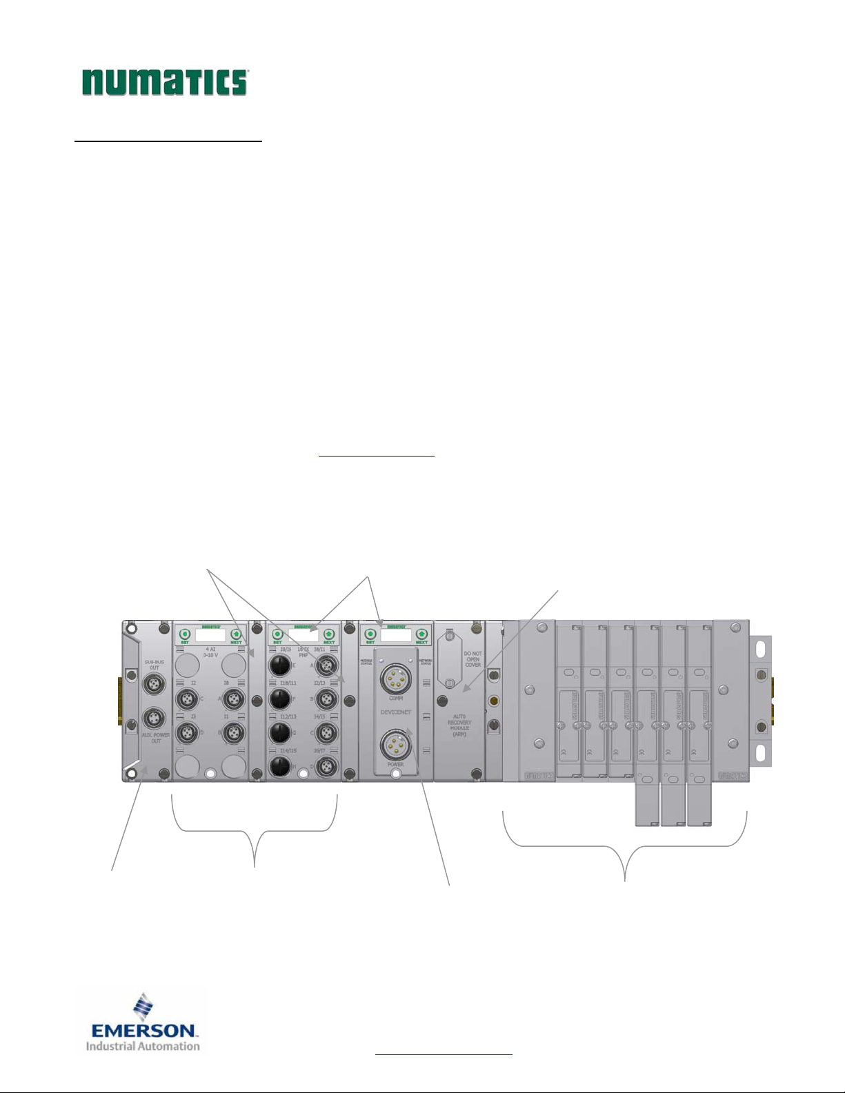
The manifold can be viewed as having two sections to it, the
Side
capable of addressing up to 1200 outputs, 1200 inputs or various combinations.
Various discrete modules with integrated graphic display are available. They include digital I/O, analog I/O,
and specialty modules which cover various application needs. Pin-outs for all connectors are labeled on the
side of the respective modules and are also detailed in the module section of this document.
This manual details specific information for configuring and commissioning the Numatics G3 Series product
line. For more information relating to pneumatic valving and valve manifold assemblies, please refer to the
Numatics
Allows easy field changes of electronic
Sub-Bus OUT
Used to distribute
additional I/O and
manifolds
supports a maximum of 32 solenoid coils and the
In Control
Clips
modules.
Discrete I/O Side
Accepts up to 16 modules in
centralized or distributed configuration
Catalog at www.numatics.com .
Graphic Display
Allows Easy Configuration
& Diagnostic reporting
Communication Module (Node)
Available with various
Industrial protocols
Valve Side
Discrete I/O Side
Automatically stores & reprograms
and the
Discrete I/O Side
supports a maximum of 16 modules
ARM
(
Auto Recovery Module)
configuration information
Valve Side
Drives up to 32 coils
. The
Valve
TDG3EPTM1-1EN 05/09
Subject to change without notice
Page 4
www.numatics.com/g3
Page 6
G3SeriesEtherNet/IPTechnicalManual
G3 Electronics Modularity
Discrete I/O
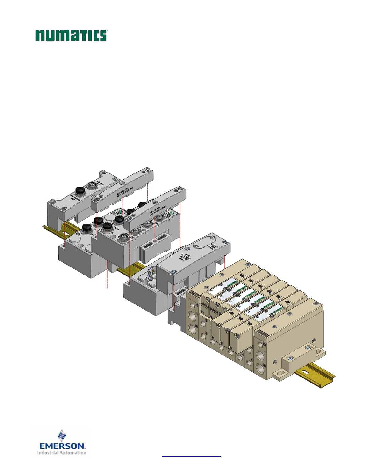
The G3 Series product line is a completely modular and scalable system. As shown below, all of the G3
electronic modules plug together, via mechanical clips, allowing easy assembly and field changes.
TDG3EPTM1-1EN 05/09
Subject to change without notice
Page 5
www.numatics.com/g3
Page 7

G3SeriesEtherNet/IPTechnicalManual
Pneumatic Valve Manifold
The pneumatic valve manifold with Internal Circuit Board Technology is also modular. The valve solenoid
coil connections are automatically made using Z-Board
internal connection from solenoid coils to output drivers without the use of wires). This allows easy assembly
and field changes.
™
technology (plug together PC boards, which allow
TDG3EPTM1-1EN 05/09
Subject to change without notice
Page 6
www.numatics.com/g3
Page 8
G3SeriesEtherNet/IPTechnicalManual
Manifold Connectors
Solenoid Coil Connections using Z-Board™ technology
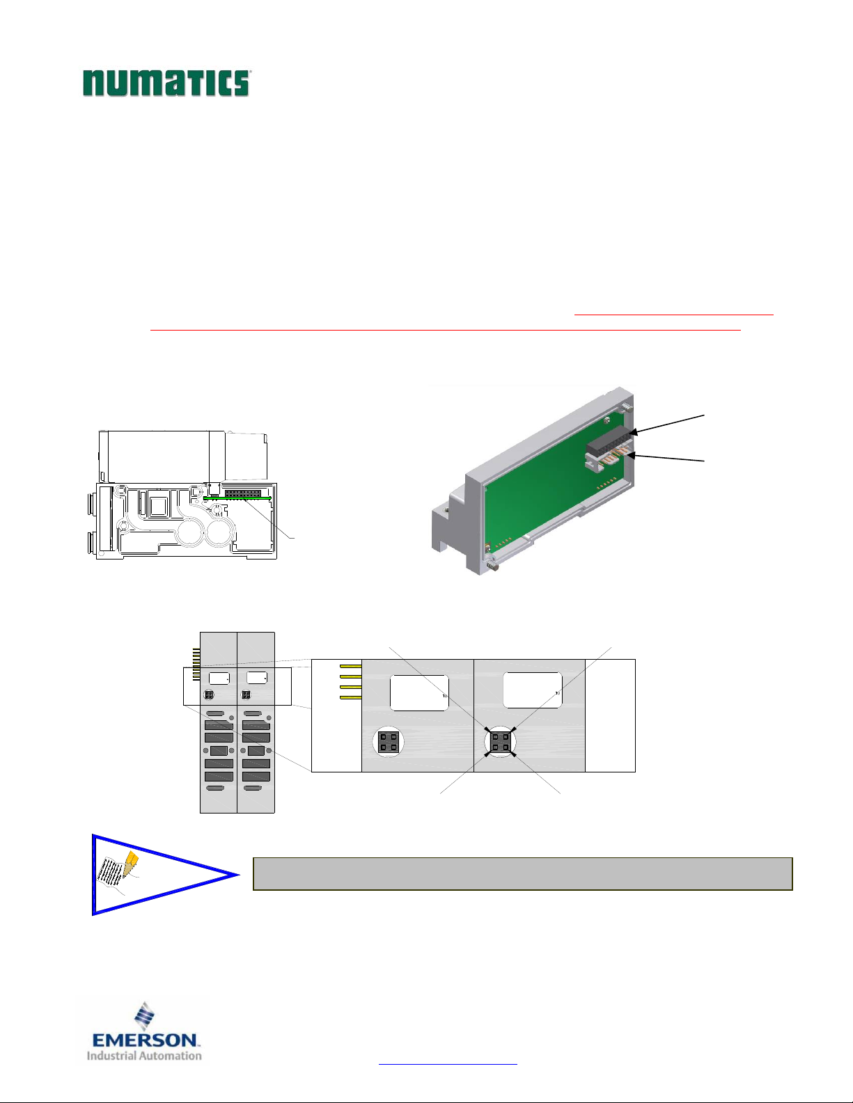
Z-Board
located in the valve adapter. The 32 available coil outputs are divided into 2 separate connector groups.
Output group No. 1 is comprised of the first output word, bits 0-15, and output group No. 2 is comprised
of the second output word, bits 16-31. Output group No. 1 connects directly to the Z-Boards
group No. 2 is connected to the Z-Boards
output (bit 0) connects to the “14” (A) solenoid on the valve closest to the communication node. The 17
– 32
solenoids on the same manifold, the 16th and 17th solenoid coils must NOT be on the same sub-base.
NOTE!
™
plug together technology connects all valve solenoids to the valve coil output driver board,
™
™
via an internal ribbon cable or valve side Sub-D. The first
nd
solenoids interconnect via the Z-Boards™ to output group No. 2. For the maximum capability of 32
. Output
Output Group
No. 1
Output Group
No. 2
Plug-in Manifold with
Intergral "Z-Board"
Eliminates Wiring
14(A) Solenoid Pin No. 1
12(B) Solenoid Pin No. 2
SINGLE
"Z-BOARD"
DOUBLE
"Z-BOARD"
Earth Ground Pin No. 3
SINGLE
"Z-BOARD"
Common Pin No. 4
DOUBLE
"Z-BOARD"
A single solenoid valve’s coil is always on the “14” end.
th
TDG3EPTM1-1EN 05/09
Subject to change without notice
Page 7
www.numatics.com/g3
Page 9
G3SeriesEtherNet/IPTechnicalManual
Z-Board™ Connectors
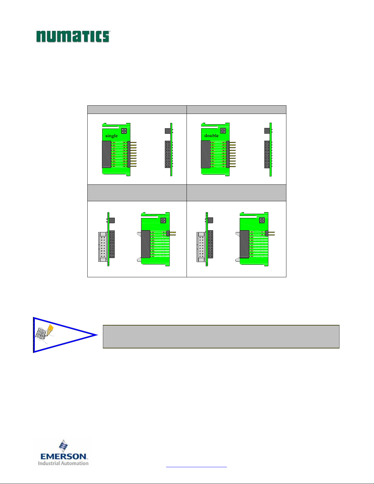
The 2005/2012/2035 valve series utilize 2 different Z-Board™ designs to achieve the single and double
solenoid output functions. This yields the possible 32 single, 16 double, or various combinations of valve
coil output capabilities.
NOTE!
Single Z-Board™ Double Z-Board
Ribbon Connection
Single Z-Board™
single
Ribbon Connection
Double Z-Board™
The 17th solenoid (output group No. 2’s first bit) must be accessed via either the
valve side Sub-D output module or a ribbon connector type Z-board.
double
™
TDG3EPTM1-1EN 05/09
Subject to change without notice
Page 8
www.numatics.com/g3
Page 10
a
G3SeriesEtherNet/IPTechnicalManual
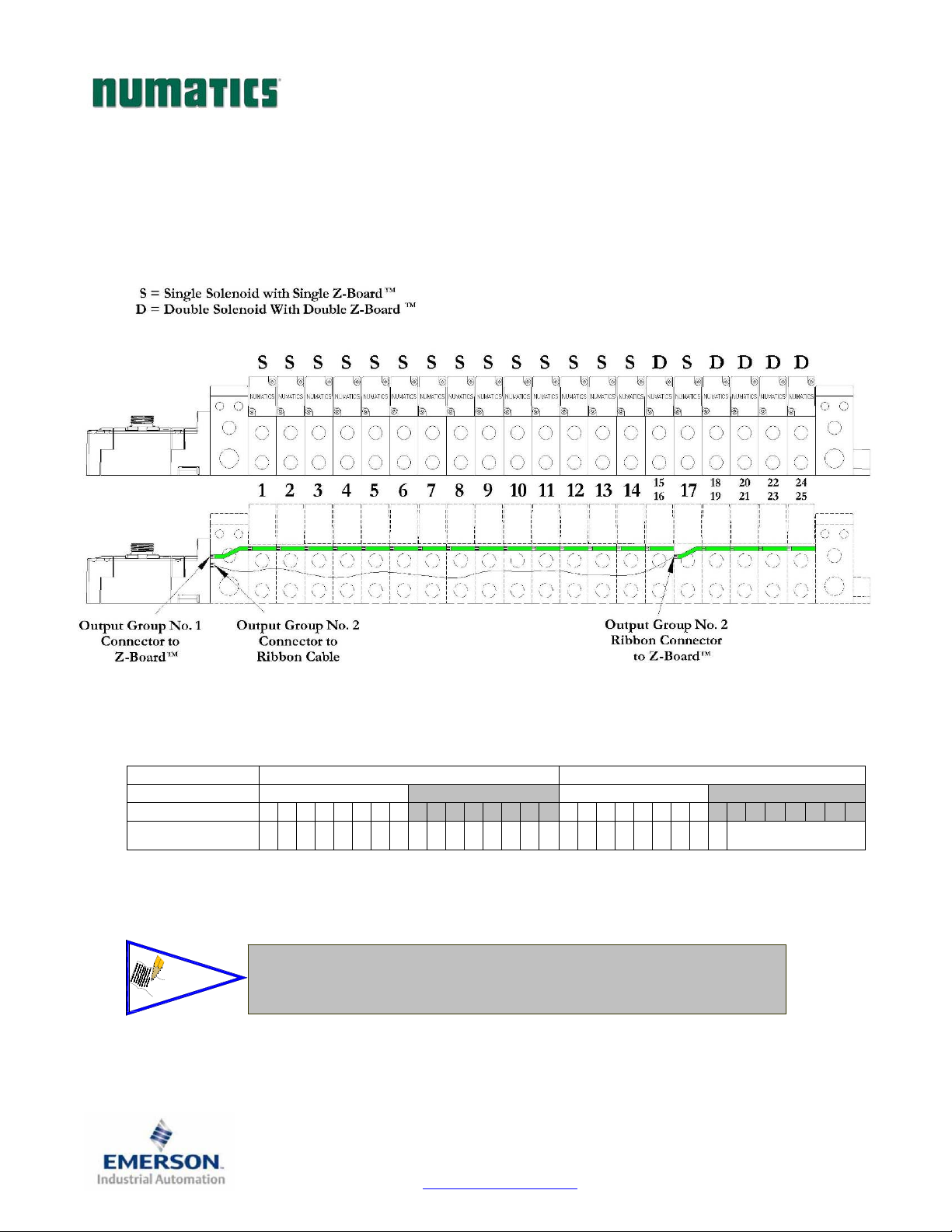
Z-Board™ and Ribbon Cable Example
If fourteen (14) single solenoid and one (1) double solenoid valves are connected directly to the
communication node via their Z-Boards
are connected to the communication node via the ribbon cable, the following would be the valve side bit
map:
Output Word 0 1
Output Byte 0 1 2 3
Output Bit No. 00 01 02 03 04 05 06 07 08 09 10 11 12 13 14 15 16 17 18 19 20 21 22 23 24 25 26 27 28 29 30 31
Solenoid Coil
Output No.
NOTE!
1 2 3 4 5 6 7 8 9 10 11 12 13 14 15 16 17 18 19 20 21 22 23 24 25 n/a
In the above example, Output Bits No. 25 thru No. 31 are allocated but
not used. Allocation may be changed by configuration changes in the
communic
tion module (node). Refer to page 23in this manual.
™
, and one (1) single solenoid and four (4) double solenoid valves
TDG3EPTM1-1EN 05/09
Subject to change without notice
Page 9
www.numatics.com/g3
Page 11
G3SeriesEtherNet/IPTechnicalManual
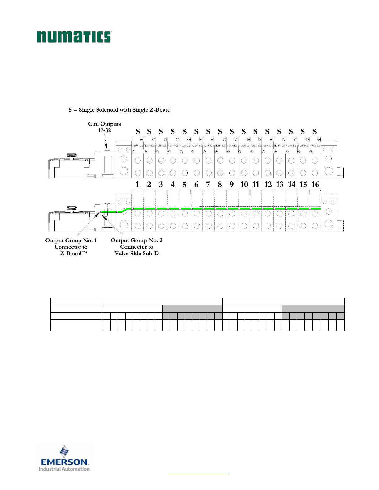
Z-Board™ with Valve Side Sub-D Example
If sixteen (16) single solenoid valves are connected directly to the communication node via their ZBoards
No. 2 connector then the following would be the valve side bit map:
Output Word 0 1
Output Byte 0 1 2 3
Output Bit No. 00 01 02 03 04 05 06 07 08 09 10 11 12 13 14 15 16 17 18 19 20 21 22 23 24 25 26 27 28 29 30 31
Solenoid Coil
™
Output No.
, and a valve side Sub-D connector is connected to the communication node via the output Group
1 2 3 4 5 6 7 8 9 10 11 12 13 14 15 16 17 18 19 20 21 22 23 24 25 26 27 28 29 30 31 32
TDG3EPTM1-1EN 05/09
Subject to change without notice
Page 10
www.numatics.com/g3
Page 12
G3SeriesEtherNet/IPTechnicalManual
Communication Module
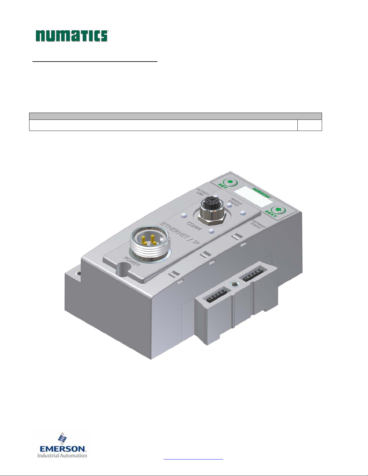
EtherNet/IP Communication Module (Node)
This module is the communication interface to the manifold. It contains communication electronics and
internal short circuit protection for power. It can be configured via software, via the graphic display or
manually via DIP switches through the optional Manual Configuration Module (MCM).
Communication Module Kit Part Number
EtherNet/IP Communication module 240-181
TDG3EPTM1-1EN 05/09
Subject to change without notice
Page 11
www.numatics.com/g3
Page 13
G3SeriesEtherNet/IPTechnicalManual
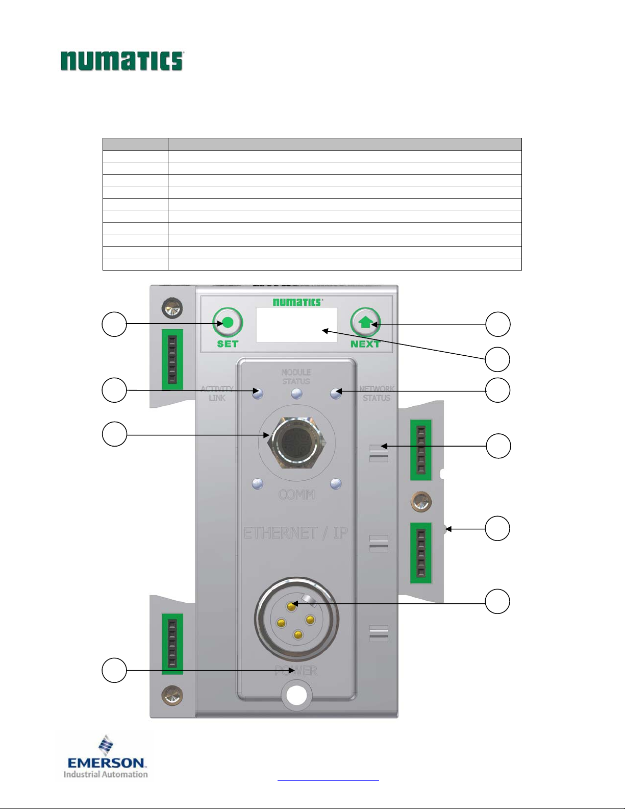
Communication Module Description
Detail No. Description
1 “Set” Button – used to navigate through user menus and to set parameters
2 Activity/Link Status LED
3 4 Pin M12 D-Coded Female Communication Connector
4 Mounting Hole
5 “Next” Button – used to navigate through user menus and to set parameters
6 Graphic Display – used to display parameter information
7 Network Status LED
8 Slot for text ID tags
9 Keying for preventing I/O module insertion
10 4 Pin MINI Male Power Connector
1
2
3
5
6
7
8
9
10
4
TDG3EPTM1-1EN 05/09
Subject to change without notice
Page 12
www.numatics.com/g3
Page 14
G3SeriesEtherNet/IPTechnicalManual
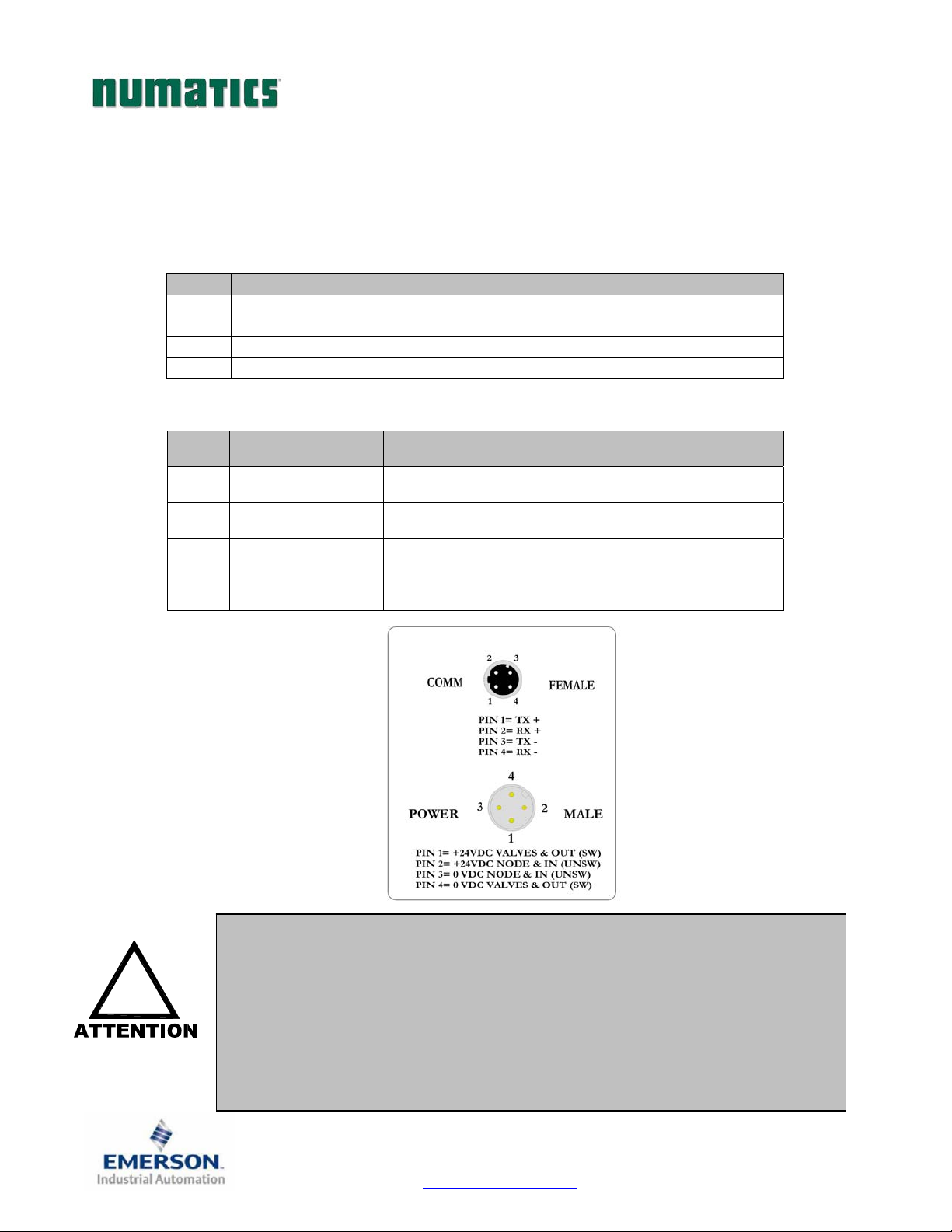
Connector Pin-Outs
Industry standard connectors are used for communication and auxiliary power. The EtherNet communication
connector is a D-coded keyway 4 pin female M12 connector. The Power connector is a single keyway
4 pin male 7/8” MINI connector.
EtherNet/IP Communication Connector Pin-Out
Pin No. Function Description
1 TX+ Positive Transmit Line
2 RX+ Positive Receive Line
3 TX- Negative Transmit Line
4 RX- Negative Receive Line
Power Connector with Cenelec Pin-Out
Cenelec
Pin No.
1
2
3
4
!
Function Description
+24 VDC
(Valves and Outputs)
+24 VDC
(Node and Inputs)
0 VDC
(Node and Inputs)
0 VDC
(Valves and Outputs)
Power common (0 VDC) pins 3 and 4 are isolated from each other to allow
separate (isolated) power supply connection if required. However, they can
be tied together if a single common, non-isolated, application is preferred.
Voltage used to power outputs
(valve coils and discrete outputs) SW
Voltage used to power discrete inputs and
node electronics UNSW
0 VDC Voltage used to power discrete inputs and
node electronics UNSW
0 VDC Voltage used to power outputs
(valve coils and discrete outputs) SW
The combined draw of the +24VDC Valves and Outputs and +24VDC Node
and Inputs pins cannot exceed 8 Amps, at any given moment in time.
The Node and Inputs pin supplies power to the node electronics. This pin
must be powered at all times for communication node to be functional.
TDG3EPTM1-1EN 05/09
Subject to change without notice
Page 13
www.numatics.com/g3
Page 15
G3SeriesEtherNet/IPTechnicalManual
Electrical Connections
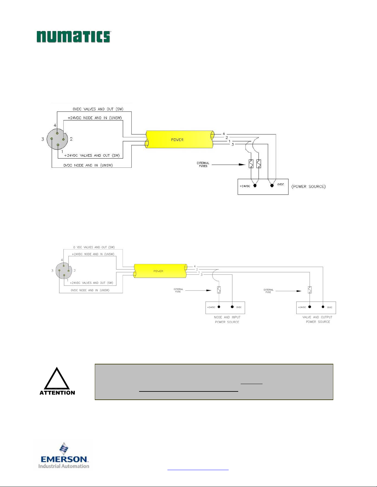
Power Connector Wiring Diagram
Power Supply Example (Non-isolated commons)
Power Supply Example (Isolated commons)
!
Please see page 17 for external fuse sizing guide.
When using molded connector power cables, Do Not rely on wire colors for
Pin-Out. Always use pin number references.
TDG3EPTM1-1EN 05/09
Subject to change without notice
Page 14
www.numatics.com/g3
Page 16
G3SeriesEtherNet/IPTechnicalManual
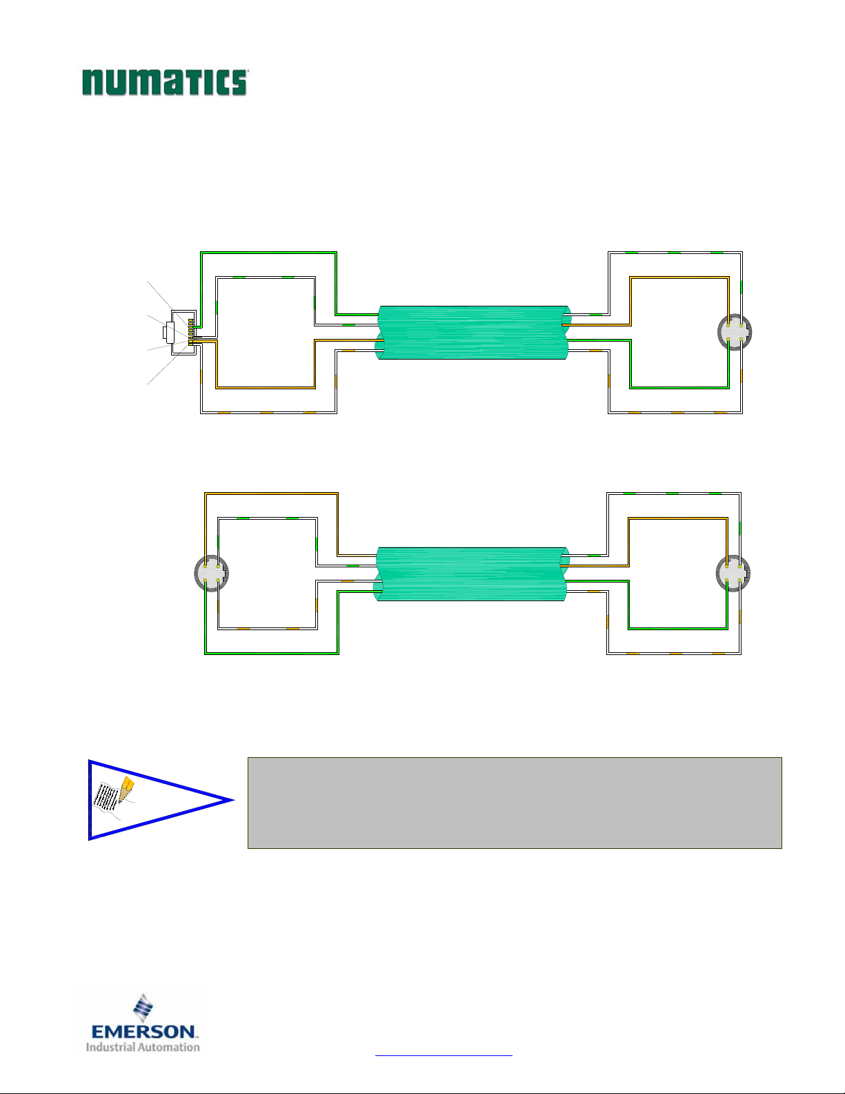
EtherNet/IPTM Straight-Through Cabling Diagrams
Straight-Through Ethernet cable is used when connecting an Ethernet node to a basic media component
(router, switch, hub, etc.). Here are some basic wiring examples of Straight-Through cabling.
RJ45 to M12 D Coded Cable
RX- (GREEN)
RX- (GREEN)
RX+ (WHITE/GREEN)
6
3
MALE
2
1
RX+ (WHITE/GREEN)
STRAIGHT-THROUGH
TX- (ORANGE)
TX+ (WHITE/ORANGE)
M12 D Coded to M12 D Coded Cable
TX- (ORANGE)
RX+ (WHITE/GREEN)
2
3
MALE
4
1
(WHITE/ORANGE)
RX- (GREEN)
TX+
STRAIGHT-THROUGH
CABLE
CABLE
TX- (ORANGE)
MALE
RX- (GREEN)
TX+ (WHITE/ORANGE)
RX+ (WHITE/GREEN)
TX- (ORANGE)
MALE
RX- (GREEN)
TX+ (WHITE/ORANGE)
2
3
4
1
2
3
4
1
NOTE!
These are examples only. For appropriate network cabling information,
please see the ODVA document titled, “EtherNet/IP
Planning and Installation Manual”.
RJ45 shown as T-568B standard.
TM
: Media
TDG3EPTM1-1EN 05/09
Subject to change without notice
Page 15
www.numatics.com/g3
Page 17
G3SeriesEtherNet/IPTechnicalManual
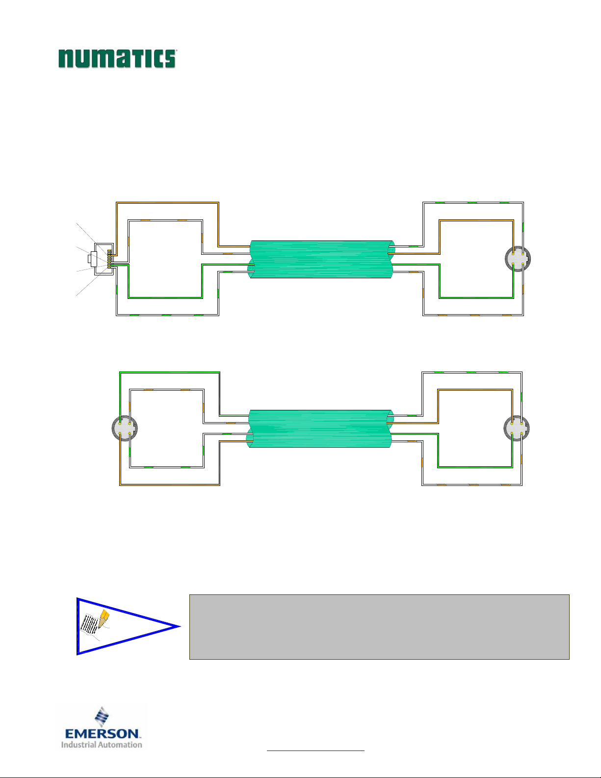
EtherNet/IPTM Crossover Cabling Diagrams
A Crossover Ethernet cable is used when connecting two Ethernet nodes directly together. For example, when
you connect a computer directly to a Numatics’ valve manifold, a Crossover cable would be used. Here are
some basic wiring examples of Crossover cabling.
RJ45 to M12 D Coded Cable
TX- (ORANGE)
RX+ (WHITE/GREEN)
6
3
MALE
2
1
TX+ (WHITE/ORANGE)
CROSSOVER CABLE
RX- (GREEN)
RX+ (WHITE/GREEN)
M12 D Coded to M12 D Coded Cable
RX- (GREEN)
TX+ (WHITE/ORANGE)
2
3
MALE
4
1
(WHITE/GREEN)
TX- (ORANGE)
RX+
CROSSOVER CABLE
TX- (ORANGE)
MALE
RX- (GREEN)
TX+ (WHITE/ORANGE)
RX+ (WHITE/GREEN)
TX- (ORANGE)
3
MALE
4
RX- (GREEN)
TX+ (WHITE/ORANGE)
2
3
4
1
2
1
NOTE!
These are examples only. For appropriate network cabling information,
please see the ODVA document titled, “EtherNet/IP
Planning and Installation Manual”.
RJ45 shown as T-568B standard.
TM
: Media
TDG3EPTM1-1EN 05/09
Subject to change without notice
Page 16
www.numatics.com/g3
Page 18

V
A
G3SeriesEtherNet/IPTechnicalManual
Power Consumption
Power Connection
C
ENELEC
Pin No.
Power Rating
The maximum system current capability is 8 Amps. Care should be taken not to exceed 8 Amp draw
Discrete I/O current draw is dependent on the device(s) connected. It is critical to know what these
Loads should not draw more than 0.5 Amps of current from any one individual discrete output point
Solenoid Valve Coil 2002 (Each) 24 VDC +10%/-15% 0.021 A 0.5 W 0 A 0 W
Solenoid Valve Coil 2005 (Each) 24 VDC +10%/-15% 0.056 A 1.35 W 0 A 0 W
Solenoid Valve Coil 2012 (Each) 24 VDC +10%/-15% 0.105 A 2.5 W 0 A 0 W
Solenoid Valve Coil 2035 (Each) 24 VDC +10%/-15% 0.105 A 2.5 W 0 A 0 W
Solenoid Valve Coil ISO - SPA 24 VDC +10%/-15% 0.167 A 4.0 W 0 A 0 W
alve Adapter (Driver) 24 VDC +/- 10% .134 A 3.22 W 0 A 0 W
Discrete Digital Input Module 24 VDC +/- 10% .012 A .29 W .085 A* 2.04 W*
Discrete Digital Output Module 24 VDC +/- 10% .051 A 1.2 W .060 A* 1.44 W*
Discrete Digital I/O Module 24 VDC +/- 10% .035 A 0.84 W .076 A* 1.82 W*
Discrete Analog Input Module (V & C) 24 VDC +/- 10% .012 A 0.288 W .077 A* 1.85 W*
Discrete Analog I/O Module (V & C) 24 VDC +/- 10% .018 A 0.432 W .087 A* 2.08 W*
Communication Module (Node) 24 VDC +/- 10% .006 A 0.144 W .091 A* 1.7 W*
Sub-Bus Valve Module 24 VDC +/- 10% .012 A 0.288 W .066 A* 1.58 W*
uto Recovery Module (ARM) 24 VDC +/- 10% 0A 0 W .022 A .53 W
Manual Configuration Module (MCM) 24 VDC +/- 10% 0 A 0 W .022 A .53 W
Function Description
1
2
3
4
+24 VDC
(Valves and Outputs)
+24 VDC
(Node and Inputs)
0 VDC Common
(Node and Inputs)
0 VDC Common
(Valves and Outputs)
Voltage used to power outputs
(valve coils and discrete outputs) SW
Voltage used to power discrete inputs and
node electronics UNSW
0 VDC (-V) Voltage used to power discrete inputs and
node electronics UNSW
0 VDC (-V) Voltage used to power outputs
(valve coils and discrete outputs) SW
through the 0VDC common pin (Current through both +24 VDC Pins combined).
values are in order to remain safely within the 8 Amp limitations.
(Contact factory for higher current capability requirements).
+24VDC
Component Voltage Tolerance
(Valves and Outputs)
Pins 1 & 4
(Node and Inputs)
Pins 2 & 3
Current Power Current Power
+24VDC
* Current depends on graphic display brightness setting. Max. value shown with high brightness.
Values decrease by approx. 12% for Medium and 25% for Low brightness settings.
NOTE!
Total power consumption for each Discrete I/O point is dependent on
the specific current draw of input sensor devices and output loads.
TDG3EPTM1-1EN 05/09
Subject to change without notice
Page 17
www.numatics.com/g3
Page 19

G3SeriesEtherNet/IPTechnicalManual
Recommended External Fuses
External fuses should be chosen based upon the physical manifold configuration. Please refer to the
table below for the fuse sizing chart.
External Fuse Sizing Chart
Power Consumption - Power Connector Pin for Valves and Outputs
Description
Number of Solenoid Valve Coils Energized Simultaneously
___ X 0.167 A (ISO - SPA Series) = __________Amps
___ X 0.105 A (2012 and 2035
Series)
___ X 0.056 A (2005 Series) = __________Amps
___ X 0.021 A (2002 Series) = __________Amps
Total load current drawn by simultaneously energized Discrete Outputs =
Number of I/O modules installed ___ X 0.008 A =
Valve Adapter =
Communication Node Power Consumption =
Total: __________Amps
Surge Compensation: X 1.25
Suggested External +24 VDC (Valves and Outputs) Fuse Value: __________Amps
Power Consumption – Power Connector Pin for Node and Inputs
Description
Communication Node Power Consumption = .091 Amps
Total load current drawn by Sensor Devices from Discrete Inputs source =
Current
= __________Amps
+
__________Amps
+
__________Amps
+
.134 Amps
+
.006 Amps
+
Current
+
__________Amps
+
Number of I/O modules installed ___ X 0.080 A = __________Amps
+
Total: __________Amps
Surge Compensation: X 1.25
Suggested External Pin +24 VDC (Node and Inputs) Fuse Value: __________Amps
*Factory Default Settings
NOTE!
The Node and Inputs Aux Power pins supply power to the node electronics. These pins must
be powered at all times for communication node and Inputs to be functional.
The internal electronic fuses exist to protect against damage due to catastrophic failure of
internal components. External fuses are always recommended for protection against power
supply failure, over-current conditions, etc…
TDG3EPTM1-1EN 05/09
Subject to change without notice
Page 18
www.numatics.com/g3
Page 20
N
N
G3SeriesEtherNet/IPTechnicalManual
Diagnostics
Communication Module LED Functions
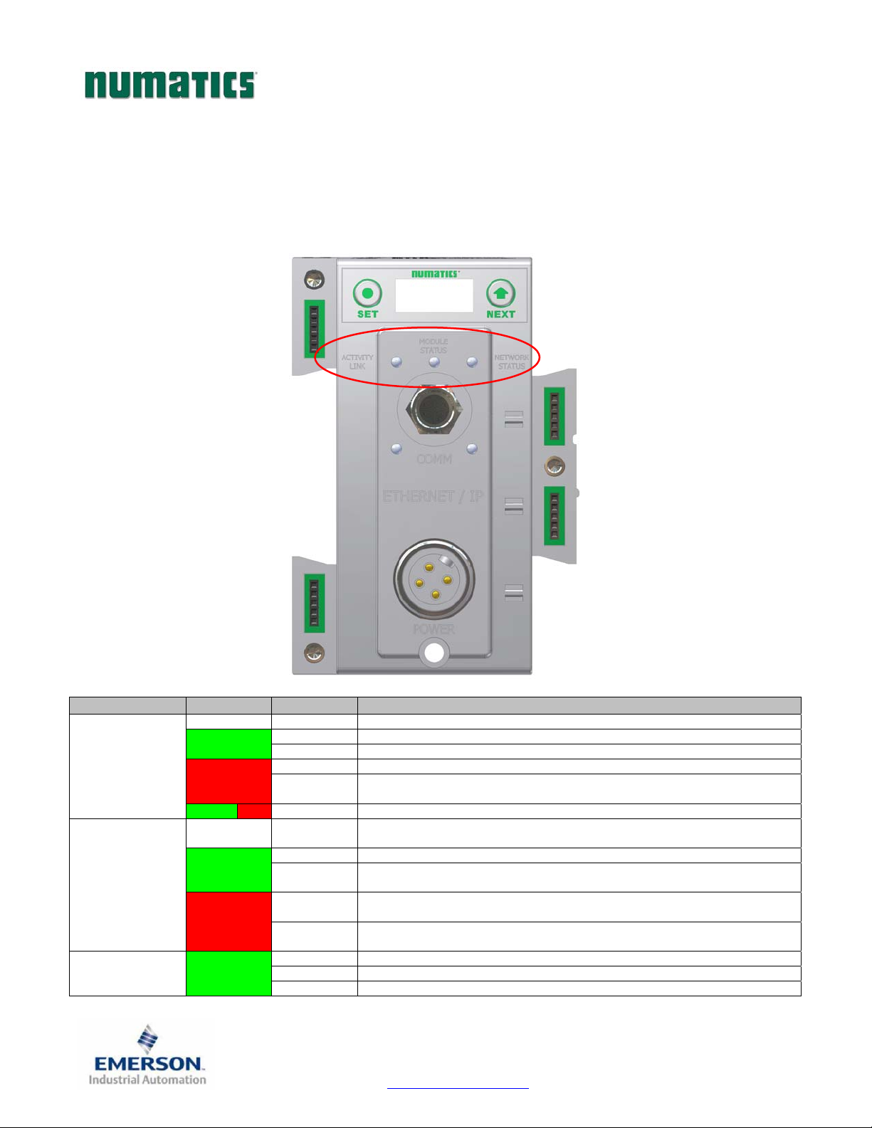
Upon power up, the LEDs indicate the status of the unit. There are three LEDs on the G3 EtherNet
node. These LEDs are described below.
LED Name Color Status Description
Off OFF No power applied to
Green
MODULE
STATUS
NETWORK
STATUS
ACTIVITY/LINK Green
Red
Green Red FLASHING Self -Test Mode.
Off OFF
Green
Red
+24V
ON Device operational. The module is operating correctly.
FLASHING Standby. The module has not been configured.
ON Major fault. A major internal error has been detected.
FLASHING
ON Connected. The module has established an EtherNet/IP connection.
FLASHING
ON
FLASHING
OFF No EtherNet connection is detected
ON The module is connected to an EtherNet network
FLASHING The LED flashes each time a packet is received or transmitted.
Minor fault. A minor recoverable fault has been detected.
Self -Test Mode - An error has occurred in the initialization process.
IP address has been not been assigned to node or no power applied to
+24V
No connection. There are no EtherNet/IP connections established to the
module.
Duplicate IP address. The module has detected that its IP address is already
being used elsewhere on the network
EtherNet/IP connection has timed out. One or more of the connections for
which this module is the target has timed out.
ODE/ IN
.
ODE/ IN
.
TDG3EPTM1-1EN 05/09
Subject to change without notice
Page 19
www.numatics.com/g3
Page 21

G3SeriesEtherNet/IPTechnicalManual
Output Short Circuit Protection
Status Bit Action During Fault Condition
Output Type
Valve Solenoid Coil Driver ON
Valve Solenoid Coil Driver OFF
Discrete Outputs ON
Output
State
Fault Condition
No Fault 0
Fault - Short Circuit, Over Temp/Over Current 1
No Fault 0
Fault - Open Load 1
No Fault 0
Fault - Short Circuit, Over Temp/Over Current 1
Status
Bit
TDG3EPTM1-1EN 05/09
Subject to change without notice
Page 20
www.numatics.com/g3
Page 22
f
S
G3SeriesEtherNet/IPTechnicalManual
G3 Graphic Display
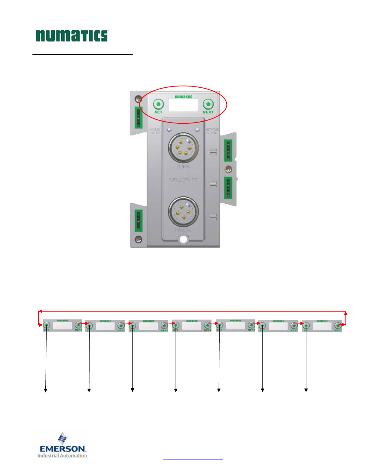
The G3 Communication and I/O modules have an integrated graphic display that may be used to configure
the parameters of the modules as well as showing diagnostic information.
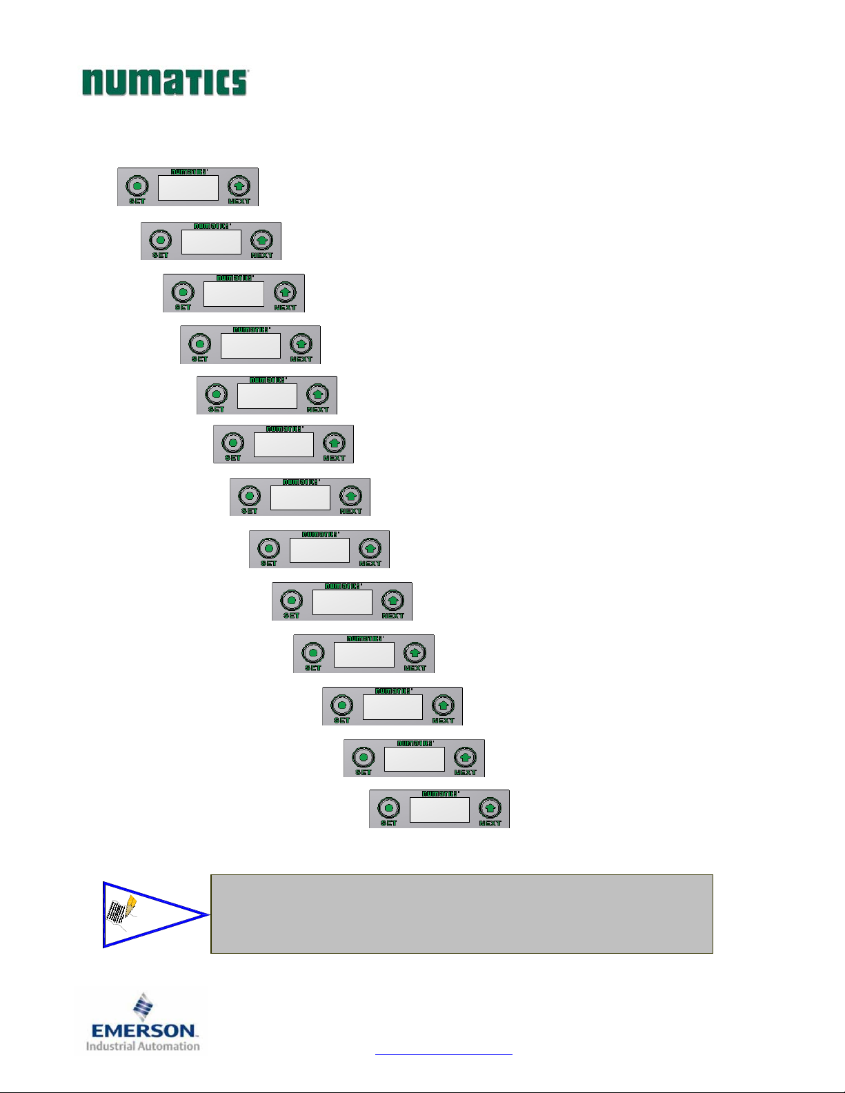
The following graphic displays represent the main menu selections of the DeviceNet communication module
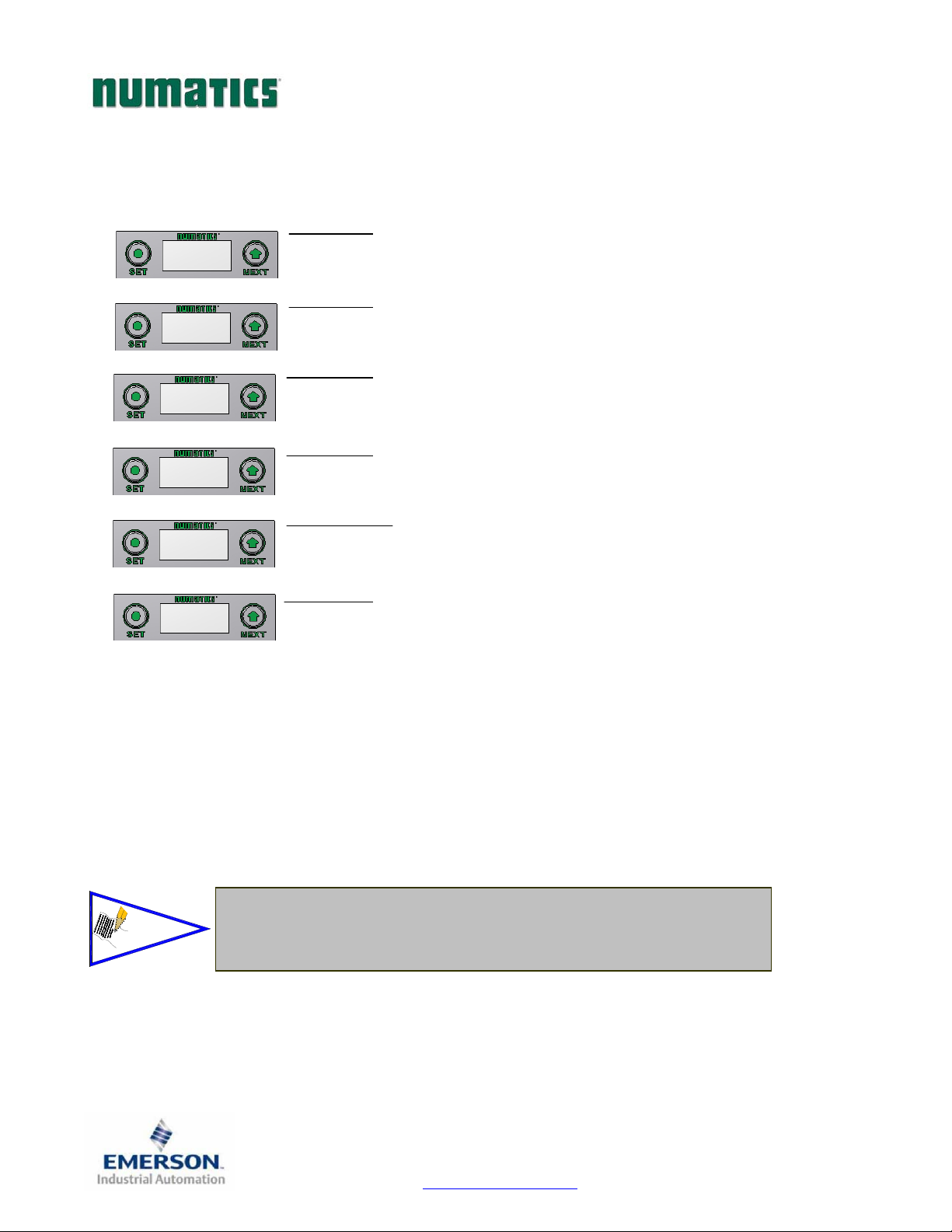
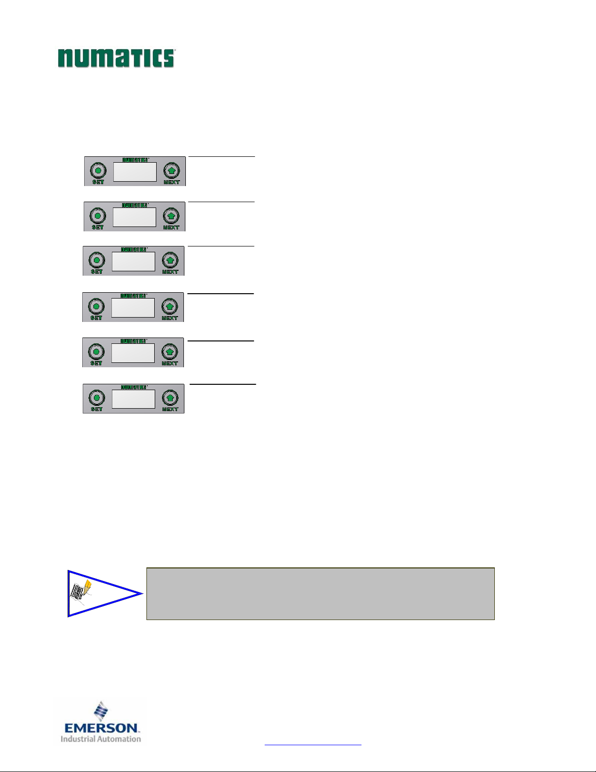
(node). Use the NEXT button to scroll through the Main menu headings shown below. At this level pressing
the SET button allows access the Sub-Menus. Please see the appropriate pages referenced below for further
details and descriptions of the Sub-Menus. Note that many of these settings can also be adjusted via software
with EDS file parameters.
MANUAL CHANGES TO NODE PARAMETERS ARE NOT ALLOWED!
NOTE: WHEN A NETWORK I/O CONNECTION IS ESTABLISHED
Home Screen
IPADDRESS
192.168.1.10
Seepage22
forSub‐Menu
SUBNETMASK
255.255.255.0
Seepage23
forSub‐Menu
DHCP‐BOOTP
DISABLED
Seepage24
forSub‐Menu
MACADDR
0.15.24.00.06.69
Seepage25
forSub‐Menu
Seepage26
forSub‐Menu
ADVANCED
ETTINGS
FACTORY
DEFAULTS
Seepage31
orSub‐Menu
DIAGNOSTICS
Seepage32
forSub‐Menu
TDG3EPTM1-1EN 05/09
Subject to change without notice
Page 21
www.numatics.com/g3
Page 23
G3SeriesEtherNet/IPTechnicalManual
IP Address Sub-Menu
IP ADDRESS
192.168.3.120
IP ADDRESS
192.168.3.120
IP ADDRESS
192.168.3.120
IP ADDRESS
092.168.3.120
ACCEPT
IP ADDR Y N
SAVE SETTINGS
NOW LATER
Steps to Set IP Address
1. Press the SET button to enter the IP ADDRESS sub-menu.
2. Press the NEXT button to select the octet that you would like to change.
Press the SET button to change the value.
3. Press the SET button to scroll through the hundred, tens and ones digits of the
octet.
Press the NEXT button to scroll through the valid digits (0-9).
Press the SET button to advance through the octet.
Press the NEXT button to advance to the next octet, scroll pass the fourth
octect to accept the entire IP Adress
4. Press the SET button to input the address shown on the display,
5. Press the NEXT button to select
the display..
a. Selecting
b. Selecting
6. Press the NEXT button to select either NOW or LATER.
a. Selecting NOW will cause the node to reset and apply the new
b. Selecting LATER will cause the new Address to be saved in
Press the SET button to confirm your choice.
No will bring you back to the main Address menu.
Yes will take you to the following SAVE SETTINGS menu
setting.
temporary memory to allow you to make additional parameter
changes before the node is reset. However, you must ACCEPT the
saved changes before your next power cycle otherwise they will be
lost.
Yes or No to accept the IP Address shown on
NOTE!
Factory default address is 192.168.3.120
0 and 255 are not valid for the fourth octet
TDG3EPTM1-1EN 05/09
Subject to change without notice
Page 22
www.numatics.com/g3
Page 24
G3SeriesEtherNet/IPTechnicalManual
Subnet Mask Sub-Menu
Steps to Set Subnet Mask
1. Press the SET button to enter the Subnet Mask sub-menu.
SUBNET MASK
255.255.255.0
SUBNET MASK
255.255.255.0
SUBNET MASK
255.255.255.0
SUBNET MASK
255.255.255.0
ACCEPT
MASK Y N
SAVE SETTINGS
NOW LATER
2. Press the NEXT button to select the octet that you would like to change.
Press the SET button to change the value.
3. Press the SET button to scroll through the hundred, tens and ones digits of the
octet.
Press the NEXT button to scroll through the valid digits (0-9).
Press the SET button to advance through the octet.
Press the NEXT button to advance to the next octet, scroll pass the fourth
octect to accept the entire Subnet Mask
4. Press the SET button to input the value shown on the display,
5. Press the NEXT button to select
on the display..
c. Selecting
d. Selecting
6. Press the NEXT button to select either NOW or LATER.
c. Selecting NOW will cause the node to reset and apply the new
d. Selecting LATER will cause the new Address to be saved in
Press the SET button to confirm your choice.
No will bring you back to the main Subnet Mask menu.
Yes will take you to the following SAVE SETTINGS menu
setting.
temporary memory to allow you to make additional parameter
changes before the node is reset. However, you must ACCEPT the
saved changes before your next power cycle otherwise they will be
lost.
Yes or No to accept the Subnet Mask shown
NOTE!
Factory default subnet mask is 255.255.255.0
TDG3EPTM1-1EN 05/09
Subject to change without notice
Page 23
www.numatics.com/g3
Page 25
G3SeriesEtherNet/IPTechnicalManual
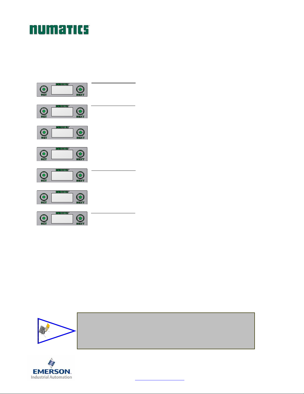
DHCP-BOOTP Sub-Menu
DHCP-BOOTP
DISABLED
DHCP-BOOTP
DISABLED
DHCP-BOOTP
ENABLED
DHCP-BOOTP
RETURN
ACCEPT
ENABLED Y N
ACCEPT
ENABLED Y N
SAVE SETTINGS
NOW LATER
NOTE!
Factory default setting for DHCP-BOOTP is enabled.
DHCP-BOOTP Steps
1. Press the SET button to enter the DHCP-BOOTP sub-menu.
2. Press the NEXT button to scroll through the choices to enable or disable the
feature.
a. ENABLED (Factory Default)
b. DISABLED
c. RETURN (this will return you to the main menu)
Press the SET button to confirm your choice.
3. Press the NEXT button to select
a. Selecting
b. Selecting
Press the SET button to confirm your choice.
No will bring you back to the main menu.
Yes will take you to the following apply changes menu.
Apply Changes Steps
4. Press the NEXT button to select either NOW or LATER.
a. Selecting NOW will cause the node to reset and apply the new
setting.
b. Selecting LATER will cause the new setting to be saved in
memory, you must accept the saved changes before your next
power cycle otherwise they will be lost.
Press the SET button to confirm your choice.
Yes or No to accept the selection.
TDG3EPTM1-1EN 05/09
Subject to change without notice
Page 24
www.numatics.com/g3
Page 26

G3SeriesEtherNet/IPTechnicalManual
MAC ADDR Menu
MAC ADDR
0.15.24.00.00.06.69
I/O Allocation Steps
1. The MAC Address is a fixed value that can not be edited.
The actual MAC ADDR has an extra leading zero. The actual number in the
example shown is 00-15-24-00-06-69
NOTE!
The MAC ADDR can not be edited
Please note that the leading 0 in this number has been left off
TDG3EPTM1-1EN 05/09
Subject to change without notice
Page 25
www.numatics.com/g3
Page 27
G3SeriesEtherNet/IPTechnicalManual
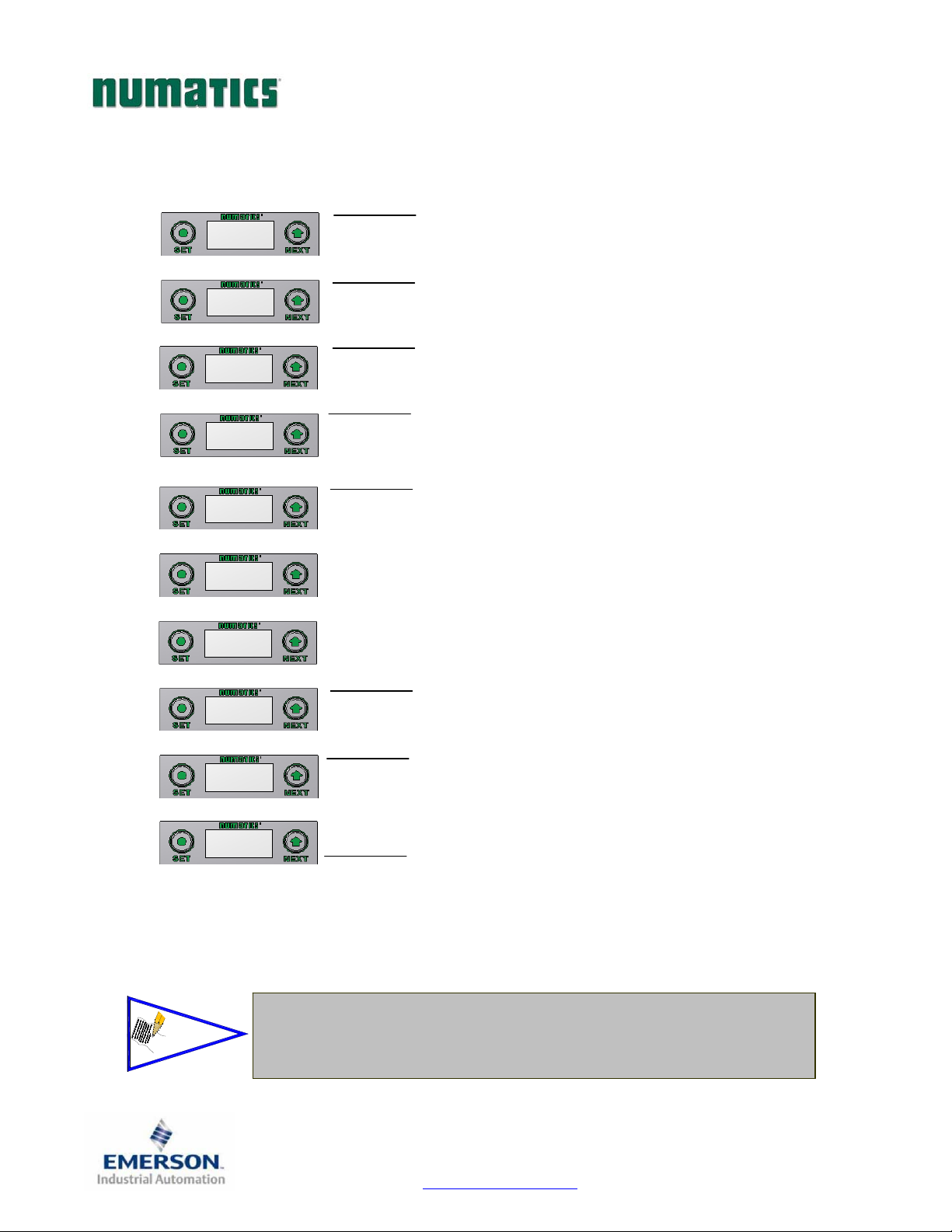
Advanced Settings - I/O Diag. Menu
ADVANCED
SETTINGS
ADVANCED MENU
SET STATUS
SET STATUS
I/O STATUS
I/O STATUS
ENABLED
I/O STATUS.
ENABLED
I/O STATUS
DISABLED
I/O STATUS
RETURN
INPUT MAPPING
WILL SHIFT
ACCEPT
DISABLED Y N
SAVE SETTINGS
NOW LATER
NOTE!
I/O Status Bits are diagnostic bits. They include the valve coil status bits,
AUX Power status bits, and Short Circuit & Alarm status bits of various
I/O modules.
I/O Status Steps
1. Press the SET button to enter the ADVANCED SETTINGS sub-menu.
2. Press the SET button to enter the ADVANCED MENU / SET STATUS.
3. Press the SET button to enter the SET STATUS / I/O STATUS.
4. The current state of the parameter is shown.
5. Press the SET button to change this parameter
Use the NEXT button to scroll through the choices to enable/disable the
Diagnostic status for I/O.
a. ENABLED (Factory Default)
b. DISABLED
6. Press NEXT to confirm the warning message.
7. Press the NEXT button to select
Save Settings Steps
8. Press the NEXT button to select either NOW or LATER.
c. RETURN (this will return you to the SET STATUS menu)
Press the SET button to confirm your choice.
a. Selecting
b. Selecting Yes will take you to the following saved settings menu.
Press the SET button to confirm your choice.
a. Selecting NOW will cause the node to reset and apply the new
b. Selecting LATER will cause the new I/O STATUS selection to be
Press the SET button to confirm your choice.
No will bring you back to the main SET STATUS menu.
setting.
saved in memory, you must Accept the saved changes before your
next power cycle otherwise they will be lost.
Yes or No to accept the selection
TDG3EPTM1-1EN 05/09
Subject to change without notice
Page 26
www.numatics.com/g3
Page 28
G3SeriesEtherNet/IPTechnicalManual
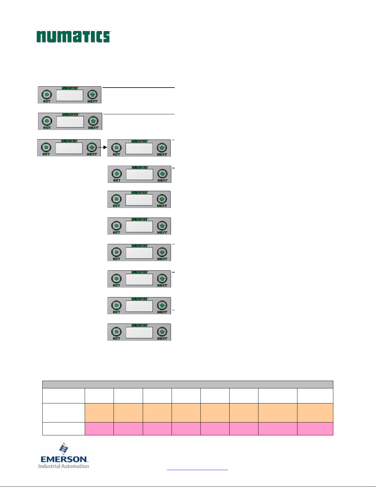
Advanced Settings - Diagnostic Word
ADVANCED
SETTINGS
ADVANCED MENU
SET STATUS
SET STATUS
IO STATUS
SET STATUS
DIAG WORD
DIAG WORD.
ENABLED
DIAG WORD.
ENABLED
NODE DIAG.
DISABLED
NODE DIAG.
RETURN
INPUT MAPPING
WILL SHIFT!
ACCEPT
DISABLED Y N
SAVE SETTINGS
NOW LATER
Diagnostic Word Format
Diag. Word Status Settings
9. Press the SET button to enter the ADVANCED SETTINGS menu.
10. Press the SET button to enter the ADVANCED MENU /SET STATUS.
11. Press the NEXT button to scroll to the SET STATUS / DIAG WORD
menu.
Press the SET button to enter the SET STATUS / DIAG WORD menu.
12. The current state of the parameter is shown.
13. Press the SET button to change this parameter
Use the NEXT button to scroll through the choices to enable/disable the
Diagnostic Word status for.
a. ENABLED (Factory Default)
b. DISABLED
c. RETURN (this will return you to the SET STATUS menu)
Press the SET button to confirm your choice.
14. Press Next to confirm the warning message.
15. Press the NEXT button to select
a. Selecting
b. Selecting
Press the SET button to confirm your choice.
No will bring you back to the main SET STATUS menu.
Yes will take you to the following saved settings menu.
Yes or No to accept the selection
Save Settings Steps
16. Press the NEXT button to select either NOW or LATER.
a. Selecting NOW will cause the node to reset and apply the new
setting.
b. Selecting LATER will cause the new NODE DIAG selection to be
saved in memory, you must Accept the saved changes before your
next power cycle otherwise they will be lost.
Press the SET button to confirm your choice.
(Comm. Status)
(Sub-Bus Status)
BYTE Bit 7 Bit 6 Bit 5 Bit 4 Bit 3 Bit 2 Bit 1 Bit 0
0
1
Reserved Reserved Reserved Reserved Reserved
Error
Code
Error
Code
Error
Code
Station
Address
Station
Address
Sub-Bus
Error
(1=Error)
Station
Address
UnSwitched
Power Status
(1=Error)
Station
Address
Switched
Power Status
(1=Error)
Station
Address
TDG3EPTM1-1EN 05/09
Subject to change without notice
Page 27
www.numatics.com/g3
Page 29
G3SeriesEtherNet/IPTechnicalManual
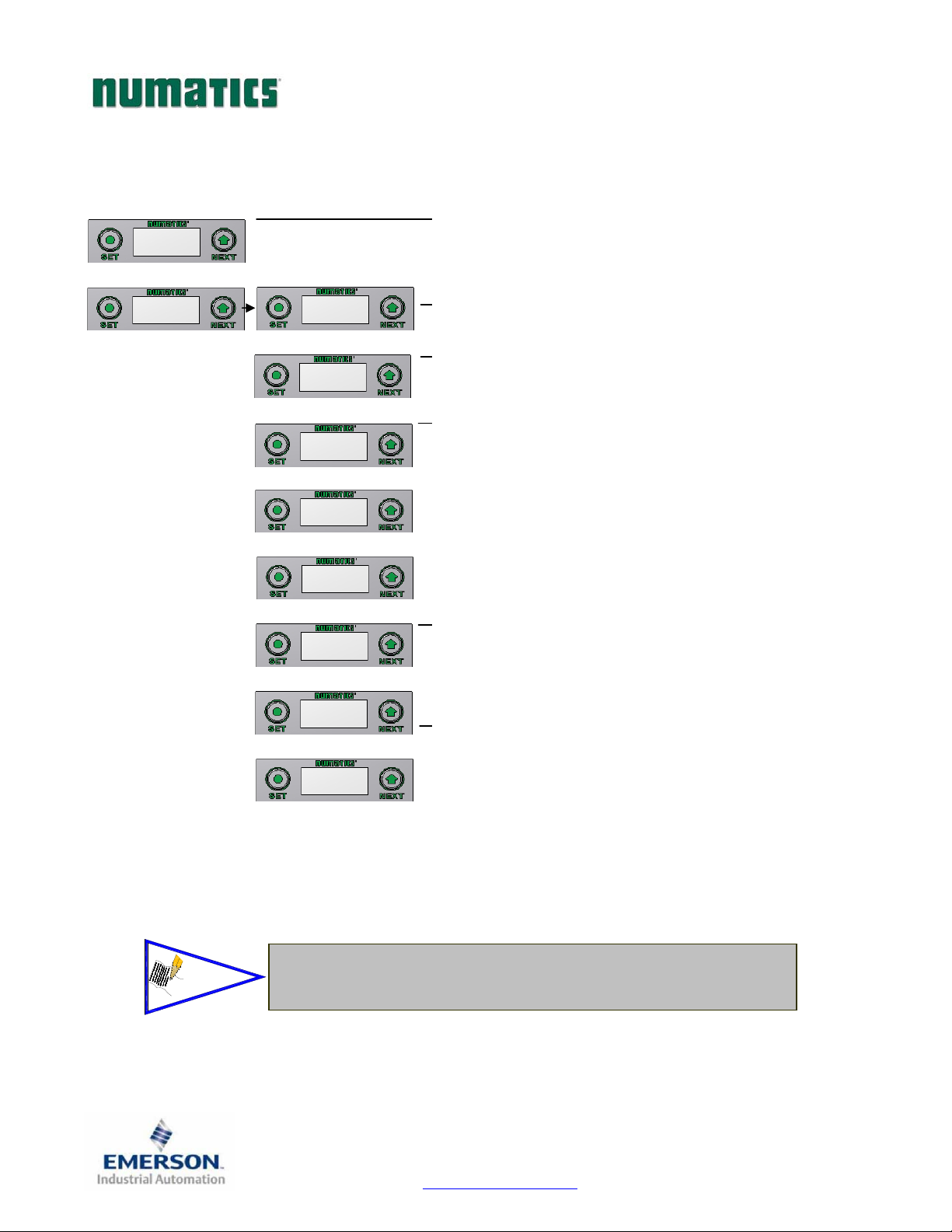
Advanced Settings - Fault Action
ADVANCED
SETTINGS
ADVANCED MENU
SET STATUS
NOTE!
ADVANCED MENU
SET FAULT IDLE
SET FAULT IDLE
FAULT ACTION
FAULT ACTION
OFF
FAULT ACTION
OFF
FAULT ACTION
HOLD LAST STATE
FAULT ACTION
RETURN
ACCEPT
OFF H.L.S. Y N
SAVE SETTINGS
NOW LATER
See page 72 for more details.
Factory Default is “ALL OFF”
Fault Action Settings
1. Press the SET button to enter the ADVANCED SETTINGS menu.
2. Press the NEXT button to scroll to the ADVANCED MENU / SET FAULT
IDLE.
3. Press the SET button to enter the ADVANCED MENU / SET FAULT IDLE.
4. Press the SET button to enter the SET FAULT IDLE / FAULT ACTION menu.
5. The current state of the parameter is shown
6. Press the SET button to change this parameter
Press the NEXT button to scroll the choices for the desired output action during
a fault state.
a. OFF (Factory Default)
b. HOLD LAST STATE
7. Press the NEXT button to select
c. RETURN (this will return you to the SET FAULT/IDLE menu)
Press the SET button to confirm your choice.
Press the SET button to confirm your choice
a. Selecting
b. Selecting
No will bring you back to the main SET FAULT/IDLE
menu.
Yes will take you to the following saved settings menu.
Yes or No to accept the selection
Save Settings Steps
8. Press the NEXT button to select either NOW or LATER.
Press the SET button to confirm your choice.
a. Selecting NOW will cause the node to reset and apply the new setting
b. Selecting LATER will cause the new FAULT ACTION selection to be
saved in memory, you must Accept the saved changes before your
Press the SET button to confirm your choice.
next power cycle otherwise they will be lost.
TDG3EPTM1-1EN 05/09
Subject to change without notice
Page 28
www.numatics.com/g3
Page 30
G3SeriesEtherNet/IPTechnicalManual
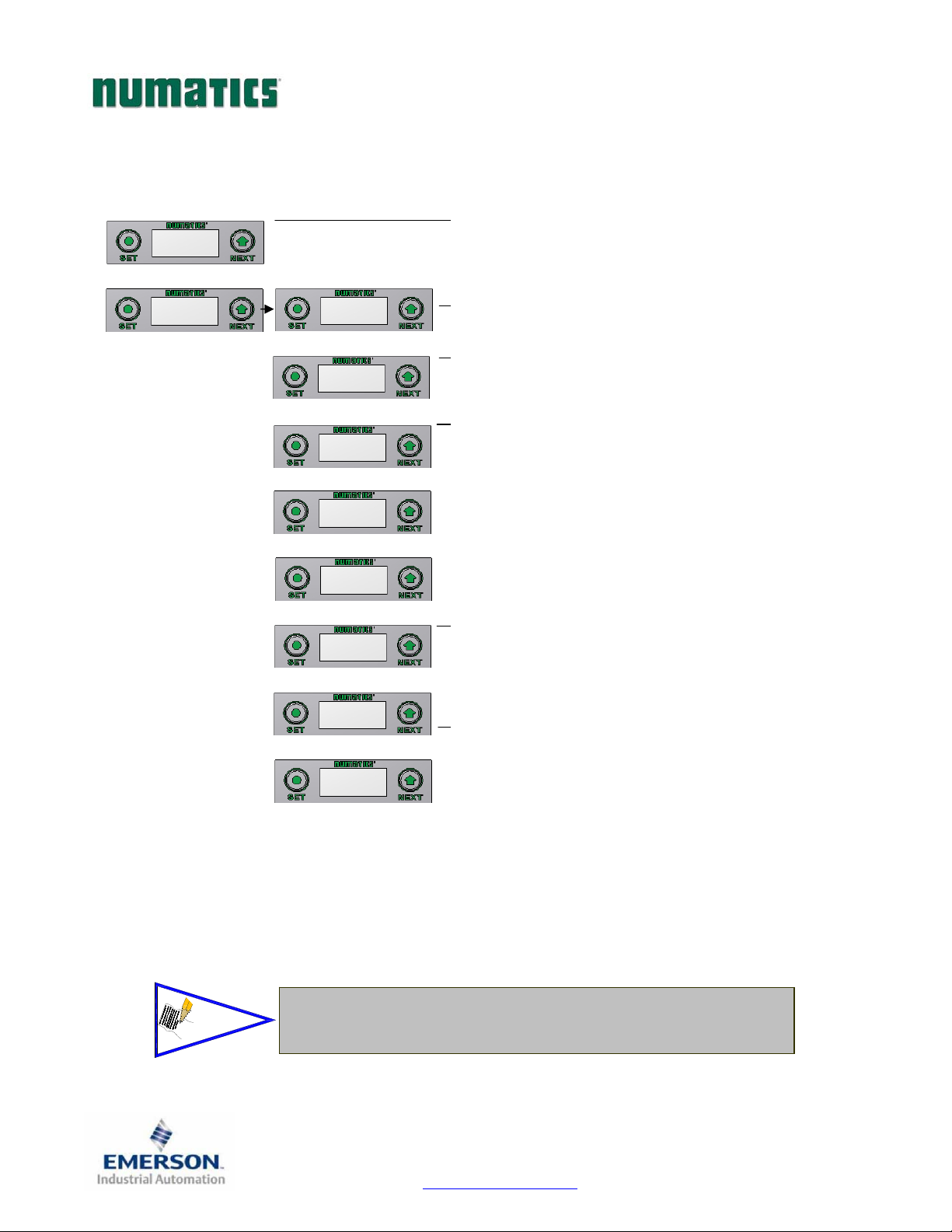
Advanced Settings - Idle Action
ADVANCED MENU
ADVANCED
SETTINGS
SET STATUS
NOTE!
ADVANCED MENU
SET FAULT IDLE
SET FAULT IDLE
IDLE ACTION
FAULT ACTION
OFF
FAULT ACTION
OFF
FAULT ACTION
HLD LAST STATE
FAULT ACTION
RETURN
ACCEPT
LAST STATE Y N
SAVE SETTINGS
NOW LATER
See page 72 for more details.
Factory Default is ALL OFF
Idle Action Settings
9. Press the SET button to enter the ADVANCED SETTINGS menu.
10. Press the NEXT button to scroll to the ADVANCED MENU / SET FAULT
IDLE.
11. Press the SET button to enter the ADVANCED MENU / SET FAULT IDLE.
12. Press the NEXT button to scroll to the IDLE ACTION menu
13. Press the SET button to enter the SET FAULT IDLE / IDLE menu.
14. The current state of the parameter is shown
15. Press the SET button to change this parameter
Press the NEXT button to scroll the choices for the desired output action during
a fault state.
d. OFF (Factory Default)
e. HOLD LAST STATE
16. Press the NEXT button to select
f. RETURN (this will return you to the SET FAULT/IDLE menu)
Press the SET button to confirm your choice.
Press the SET button to confirm your choice
c. Selecting
d. Selecting
No will bring you back to the main SET FAULT/IDLE
menu.
Yes will take you to the following saved settings menu.
Yes or No to accept the selection
Save Settings Steps
17. Press the NEXT button to select either NOW or LATER.
Press the SET button to confirm your choice.
c. Selecting NOW will cause the node to reset and apply the new setting
d. Selecting LATER will cause the new FAULT ACTION selection to be
saved in memory, you must Accept the saved changes before your
Press the SET button to confirm your choice.
next power cycle otherwise they will be lost.
TDG3EPTM1-1EN 05/09
Subject to change without notice
Page 29
www.numatics.com/g3
Page 31
G3SeriesEtherNet/IPTechnicalManual
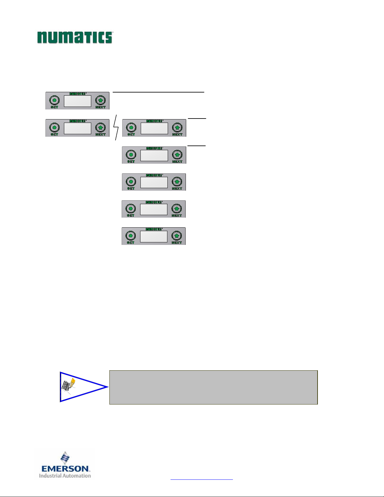
Advanced Settings - Brightness
ADVANCED
SETTINGS
ADVANCED MENU
SET STATUS
ADVANCED MENU
SET BRIGHTNESS
BRIGHTNESS
HIGH
BRIGHTNESS
LOW
BRIGHTNESS
MEDIUM
BRIGHTNESS
HIGH
Brightness Settings
1. Press the SET button to enter the ADVANCED SETTINGS menu.
2. Press the NEXT button to scroll to the CONFIG MENU / SET
BRIGHTNESS.
Press the SET button to enter the CONFIG MENU / SET BRIGHTNESS.
3. The current state of the parameter is shown
4. Press the SET button to change this parameter
Press the NEXT button to scroll the choices for the desired brightness of the
graphic display for all modules on the G3 system.
a. LOW
b. MEDIUM
c. HIGH (Factory Default)
Press the SET button to confirm your choice. The changes will take effect
immediately.
This a global setting that affects all modules
NOTE!
Each module, however, has its own setting if different settings
are required.
TDG3EPTM1-1EN 05/09
Subject to change without notice
Page 30
www.numatics.com/g3
Page 32
G3SeriesEtherNet/IPTechnicalManual
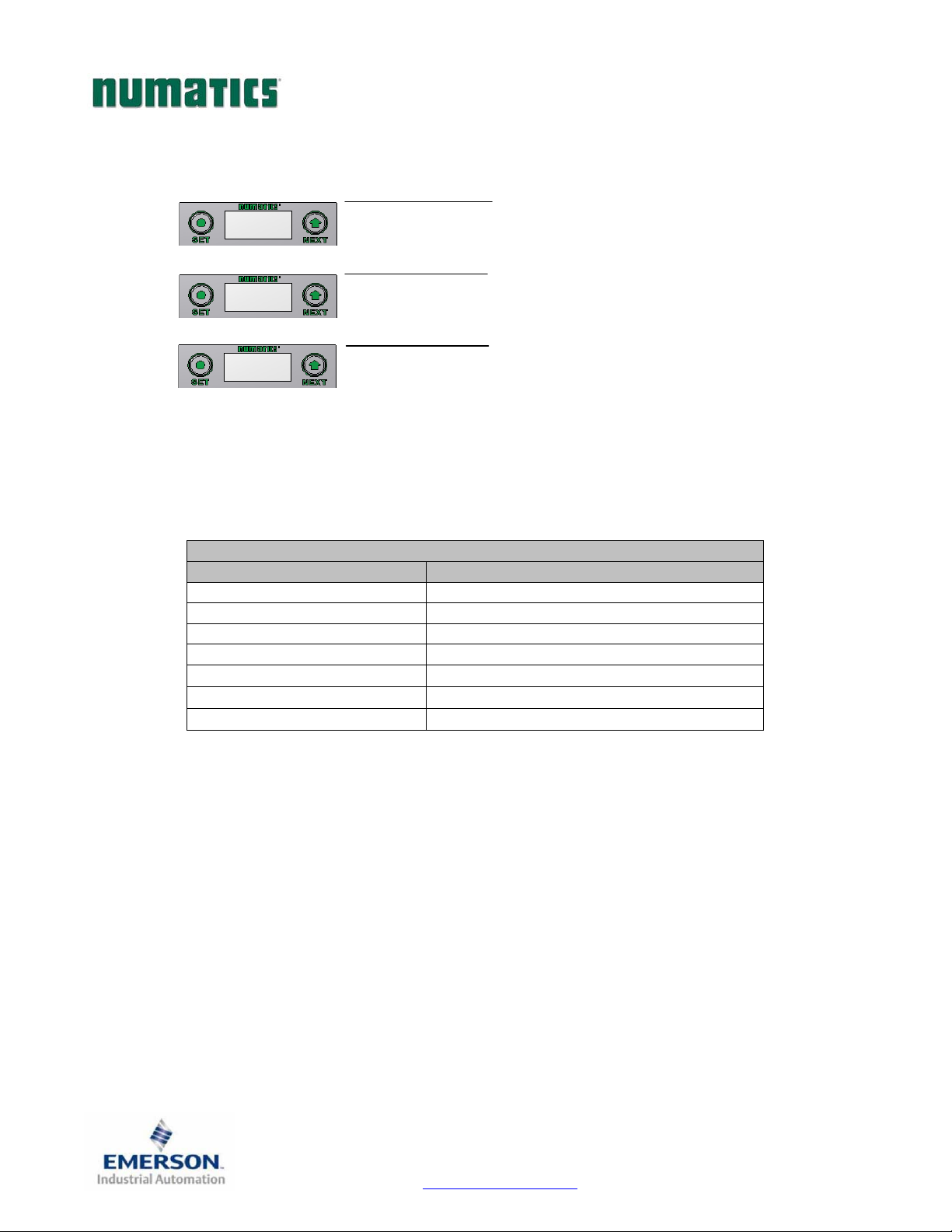
Factory Defaults
FACTORY
DEFAULTS
SET DEFAULTS
NO
SET DEFAULTS
NO
Factory Default Settings
1. Press the SET button to enter the FACTORY DEFAULTS sub-menu.
2. Press the SET button to change this parameter
3. Press the NEXT button to select Yes or No.
a. Selecting No will bring you back to the main FACTORY
DEFAULTS menu.
b. Selecting Yes will cause the node to reset and return all
parameters to the factory default conditions.
c.
Selecting RETUTN will bring you back to the main FACTORY
DEFAULS menu
Press the SET button to confirm your choice.
FACTORY DEFAULT SETTINGS
Description Default
IP Address 193.168.3.120
Sub Net Mask 255.255.255.0
Diagnostic Word Enabled
I/O Diagnostic Status Enabled
Fault Action Reset to All Off
Idle Action Reset to All Off
Brightness High
TDG3EPTM1-1EN 05/09
Subject to change without notice
Page 31
www.numatics.com/g3
Page 33
G3SeriesEtherNet/IPTechnicalManual
Diagnostics - Self Test Mode
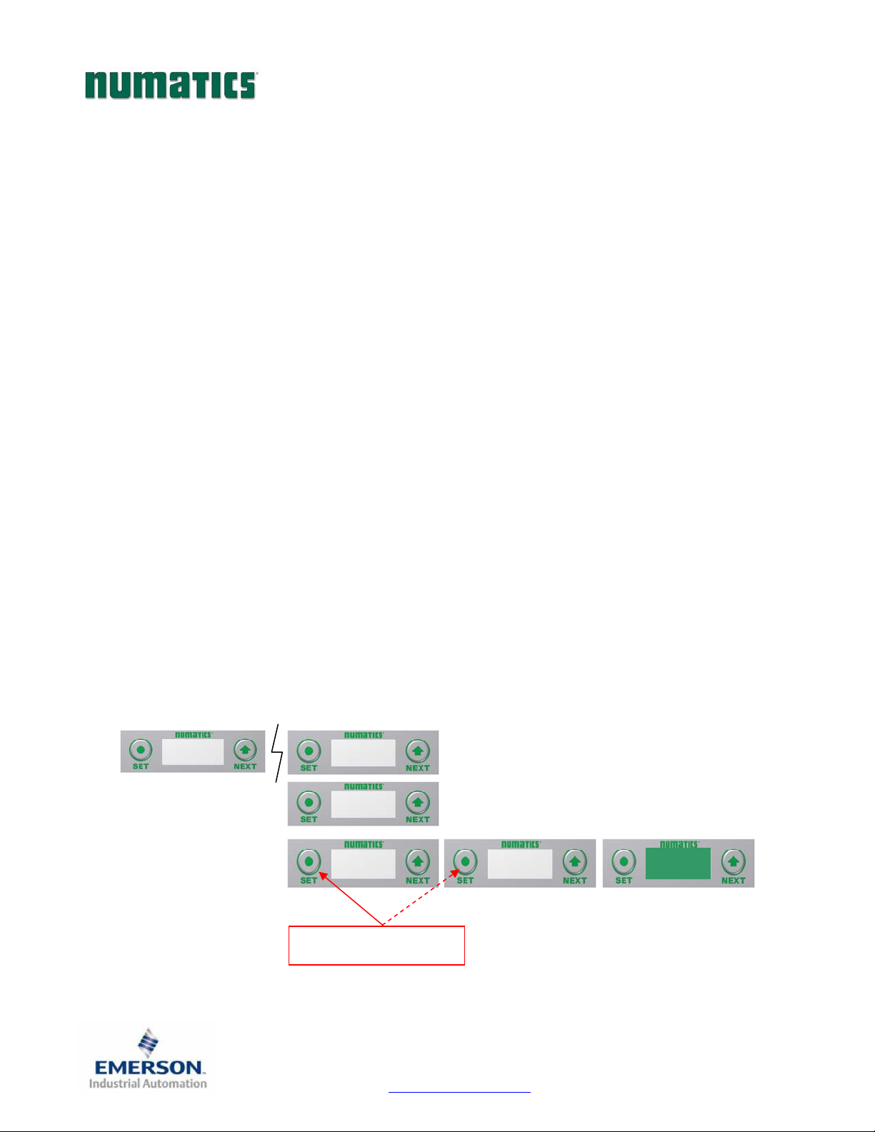
An internal diagnostic tool can be enabled on the communication module (node) using the graphic display.
This tool allows the user to confirm that all of the inputs and outputs on the manifold and any of the
distributed modules are fully functional without needing a network connection or controller. There are two test
modes that the user can choose. The “
turning them ON and OFF for approximately .5 seconds. The “
causing all of the outputs to toggle between even and odd values when any input is made. The Self Test mode
on the communication module (node) is a global setting and will test all devices connected on the main
manifold as well as any distributed modules and/or manifolds.
Similar “local” self tests are available on all output modules types. This “local” self test function allows any
output module to be tested without affecting any other output module.
NOTE: The number of Valve outputs that are tested are affected by the I/O size settings.
To use the Self Test Mode, the user must first set some initial conditions. Follow these steps to initiate the
self-test mode.
1) Disconnect Air and Communication from the manifold!
2) Select the desired test mode using the graphic display. (See example below)
3) Starting at the Home Screen, navigate the menus by selecting the NEXT button until the
DIAGNOSTICS menu is shown.
4) Select the SET button to access the
SELF-TEST menu
5) Push NEXT to navigate to the desired test mode:
6) Push SET to select the desired test mode.
7) A message will appear:
8) Hold the SET button down for approximately 10 seconds to enable the test. The Display will flash
the above message while the button is pushed.
9) When the display stops flashing, the self-test mode will run and the Module Status LED will flash
Red/Green while the display shows
10) The global self-test mode can only be disabled by disconnecting the power to the manifold.
CYCLE OUTPUTS” test mode tests all the outputs by sequentially
INPUTS” test mode tests the inputs by
DIAGNOSTICS menu and then again to access the
CYCLE OUTPUTS or INPUTS
DISCONNECT AIR HOLD SET BUTTON
SELF TEST RUNNING.
IPADDRESS
192.168.3.120
DIAGNOSTICS
DIAGNOSTICS
SETSELF‐TEST
SETSELFTEST
CYCLEOUTPUTS
HOLDFOR10SECONDSTO
INITIATE
SETSELF‐TEST
INPUTS
DISCONNECTAIR
HOLDSET
BUTTON
TDG3EPTM1-1EN 05/09
Subject to change without notice
Page 32
www.numatics.com/g3
Page 34
G3SeriesEtherNet/IPTechnicalManual
Diagnostics Cont.
DIAGNOSTICS
USNW POWER
24.83 V
NETWORK
ERRORS
MAIN NETWORK
MAIN NETWORK
NO ERRORS
SUB-NETWORK
SUB-NETWORK
NO ERRORS
FIRMWARE REV.
1.1
1. All diagnostic information is read only
2. Press the SET button to enter DIAGNOSTICS sub-menu.
3. Press the NEXT button to scroll through the main diagnostic menu choices.
a. UNSW POWER
i. - Displays voltage level of unswitched power (Node & Inputs)
b. NETWORK ERRORS - ERROR CODE
i. - Displays fieldbus network errors
c. MAIN NETWORK
i. - Displays
d. SUB-NETWORK
i. - Displays log of network errors
e. FIRMWARE REV.
i. - For service personnel
f. FIRMWARE BUILD
i. For service personnel
g. BOOTCODE REV.
i. -For service personnel
h. BOOTCODE BUILD
i.
j. PART NUMBER
i. - Displays replacement part number of module
NOTE!
FIRMWARE BUILD
XXXXX
LOAD
FIRMWARE
BOOTCODE REV.
1.0
BOOTCODE BUILD
XXXXX
PART NUMBER
240-181
The UNSW POWER screen indicates the voltage level present on the UNSW
(Node & Input) power pins (Pin No. 2 and 3) of the main power connector.
A voltage level less than 19 volts will generate an error screen and an
associated diagnostic bit (see ‘Diagnostic’ section for more details).
TDG3EPTM1-1EN 05/09
Subject to change without notice
Page 33
www.numatics.com/g3
Page 35
G3SeriesEtherNet/IPTechnicalManual
Error Messages
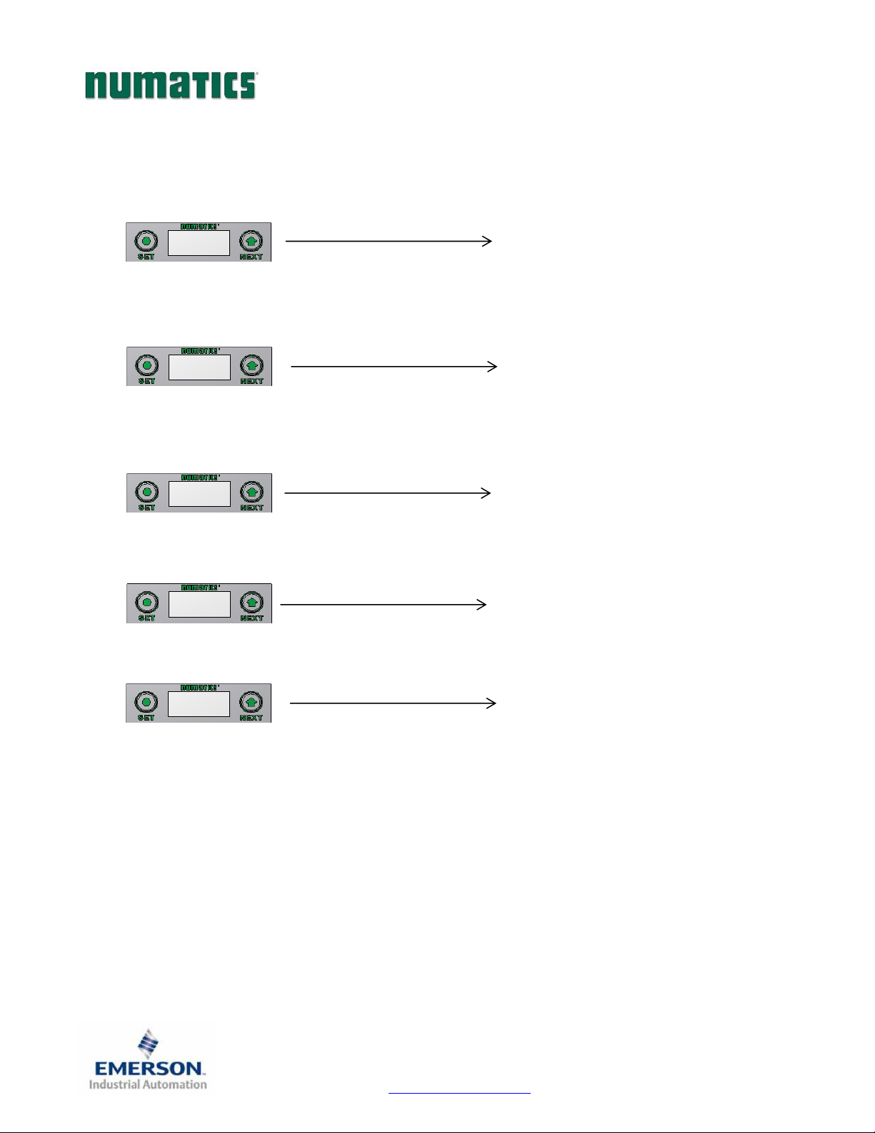
The following are automatic error messages that are displayed when specific faults occur during operation:
SUB-BUS SHORT
SHORTED COIL
NO. X
MISSING MODULE
NUMBER X
Displayed when a short circuit condition is
detected on the Sub-Bus power lines.
Displayed when a short circuit condition is
detected on a valve coil
Displayed when a Sub-Bus module that had
been previously installed becomes absent from
the configuration
VALVE/ OUTPUT
POWER OFF
UNSWITCHED
POWER LOW
Displayed when +24 VDC on
Pin No. 1 & 4 (Valves and Outputs) is not
present or below 22 VDC
Displayed when +24 VDC on
Pin No. 2 & 3 (Node and Inputs) is below
19 VDC
TDG3EPTM1-1EN 05/09
Subject to change without notice
Page 34
www.numatics.com/g3
Page 36
G3SeriesEtherNet/IPTechnicalManual
MCM – Manual Configuration Module (Optional)
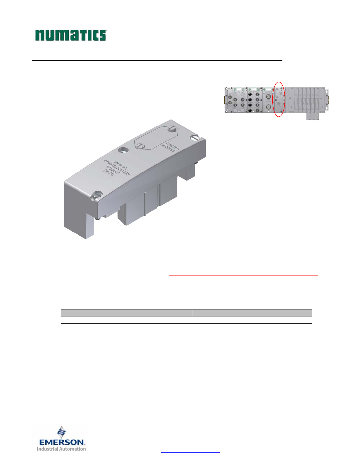
The MCM is an optional module that is installed between the node and the valve adapter module and allows
the user to manually set the last octet of the IP address without the need for software configuration or the use
of the integrated graphic display in the node. If software configuration or configuration via the integrated
graphic display in the node is preferred, this module is not necessary.
Description Replacement Part Number
Complete Module 240-186
TDG3EPTM1-1EN 05/09
Subject to change without notice
Page 35
www.numatics.com/g3
Page 37
G3SeriesEtherNet/IPTechnicalManual
DIP Switch Settings
IP Address:
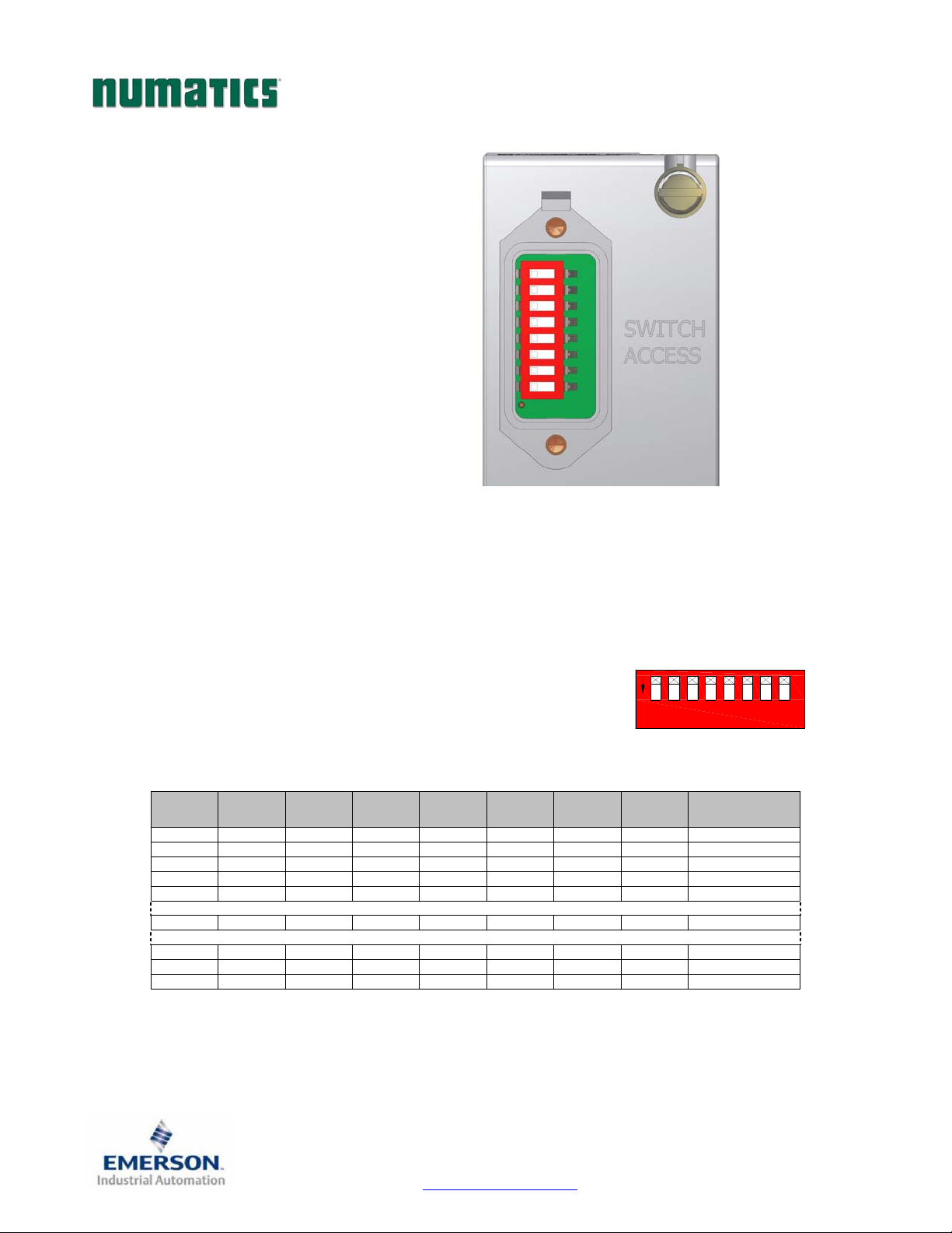
The DIP switches provide a manual way to configure the node’s IP address. The values of the first, second
and third octets are factory set to 192.168.001, respectively. The switches set the binary value of the last octet in
the IP address. When all DIP switches are set to OFF, manual configuration is disabled and other means of
setting the IP address must be used. DIP switch configuration settings require power to be cycled before any
changes will take effect.
IP address: 192.168.001.XXX (192.168.001.SW1)
Subnet Mask 255.255.255.0
Gateway address: 0.0.0.0 (no gateway set)
XXX = DIP switch setting per the table below
27=128
SW-8
OFF OFF OFF OFF OFF OFF OFF OFF 0*
OFF OFF OFF OFF OFF OFF OFF ON 1
OFF OFF OFF OFF OFF OFF ON OFF 2
OFF OFF OFF OFF OFF OFF ON ON 3
OFF OFF OFF OFF OFF ON OFF OFF 4
OFF ON ON ON ON OFF OFF OFF 120
ON ON ON ON ON ON OFF ON 253
ON ON ON ON ON ON ON OFF 254
ON ON ON ON ON ON ON ON 255*
26=64
SW-7
25=32
SW-6
24=16
SW-5
23=8
SW-4
22=4
SW-3
21=2
SW-2
1
ON
All switches shown in
the "OFF" position.
20=1
SW-1
*Not valid for fourth octet
4
3
2
Octet Value
(Decimal)
5
8
6
7
TDG3EPTM1-1EN 05/09
Subject to change without notice
Page 36
www.numatics.com/g3
Page 38
G3SeriesEtherNet/IPTechnicalManual
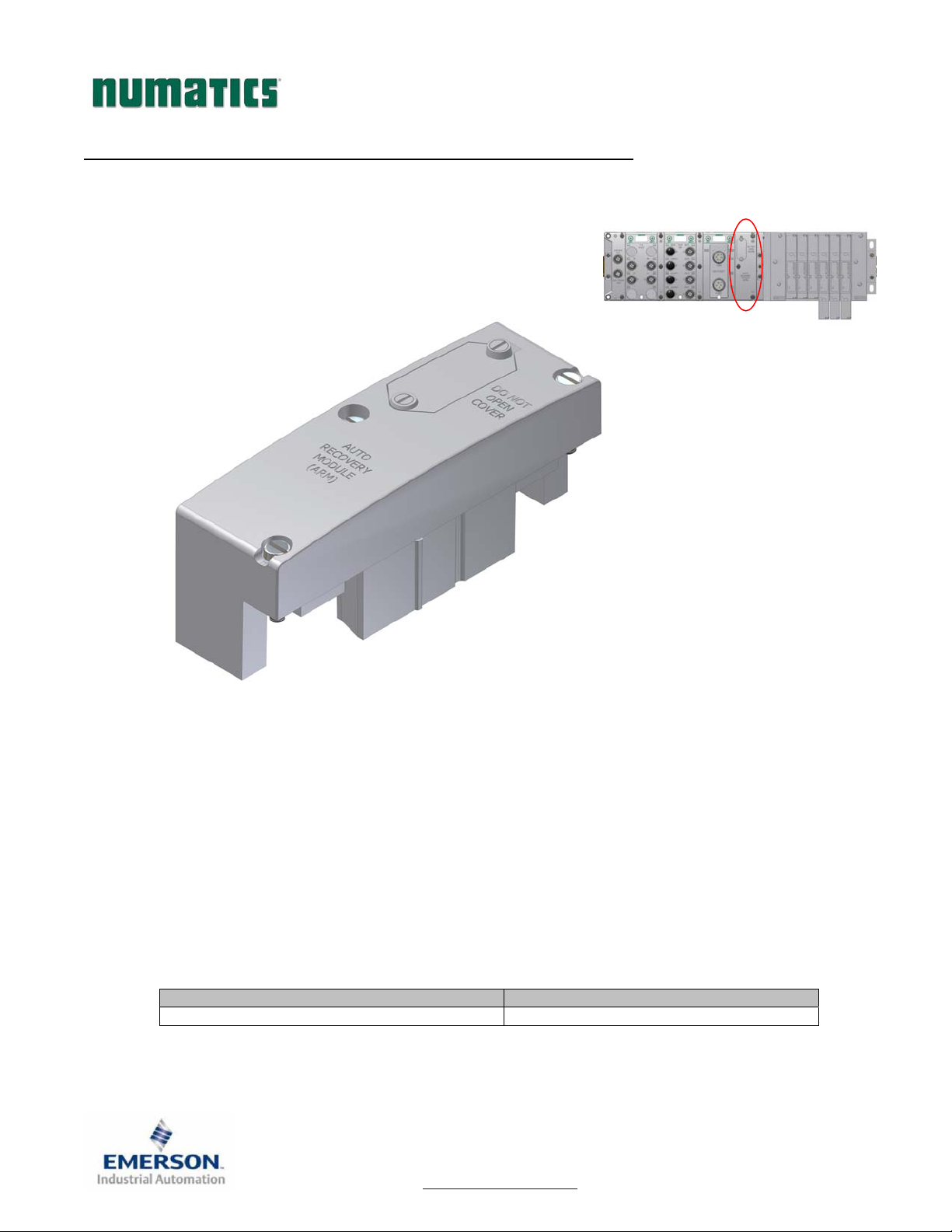
ARM – Auto Recovery Module (Optional)
The Auto Recovery Module (ARM) is an optional memory module that is installed between the node and
the valve adapter module and is used to preserve the manifold configuration settings even during
catastrophic failure. During the power-up process it reads the configuration of the manifold, including
any user settable parameters of I/O modules, and stores the information in its non volatile memory. Once
the information is stored, it automatically disconnects itself from the power circuits while still
mechanically attached to the manifold. Upon power-up it reconnects itself and compares the stored
configuration settings to the actual manifold configuration. If these settings are different it gives the user
the option of:
1. Updating the manifold setting with the stored values
2. Updating the ARM module with the current settings
3. Continue operation with present configuration without updating ARM
Description Replacement Part Number
Complete ARM Module 240-182
TDG3EPTM1-1EN 05/09
Subject to change without notice
Page 37
www.numatics.com/g3
Page 39
w
pply
G3SeriesEtherNet/IPTechnicalManual
Distribution
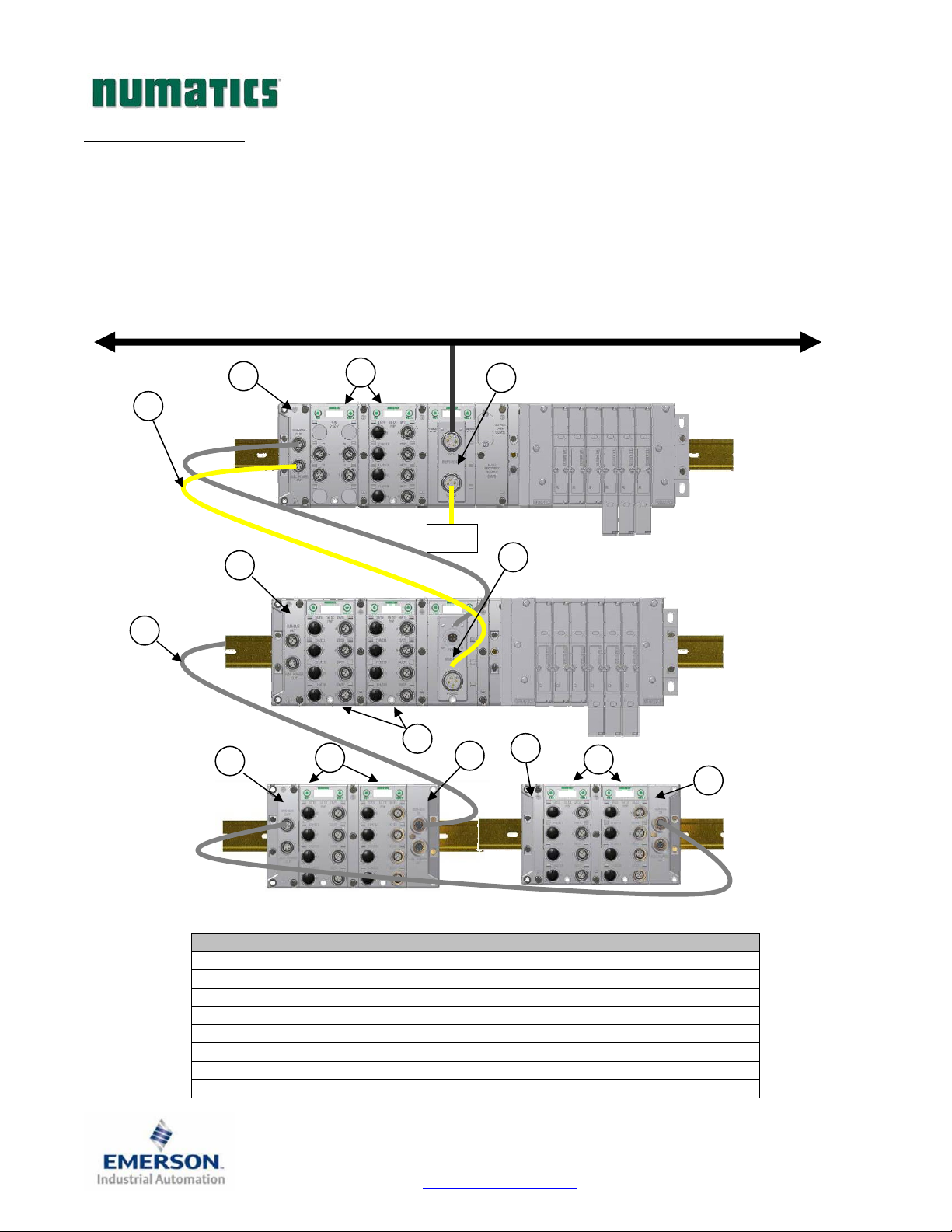
Distribution of I/O capability can be easily achieved with the G3 platform by means of Sub-Bus modules.
I/O modules, valve manifolds and/or a combination of both can be simply separated from the main manifold
and distributed via a sub-bus communication cable. The G3 platform uses the same I/O modules on the
main manifold as on the distribution chain. The main communication module can control up to 16 I/O
modules either on the main manifold or as part of the sub-bus connections. To utilize the sub-bus
distribution capabilities the Sub-Bus OUT module must be located on the end of the main communication
manifold and a Terminator Module must be located at the last sub-bus component.
Example 1
2
5
5
7
1
Power
Su
3
6
5
7
7
4
8
Detail No. Description
1 Main Communication Module (Node)
2 Sub-Bus Power Cable (Can be connected to additional power supply)
3 Distributed Sub-Bus Valve Module
4 Sub-Bus IN module
5 Sub-Bus OUT module
6 Sub-Bus Communication Cable
7 I/O Modules
8 Terminator Module
Fieldbus network
Main Fieldbus
Valve Manifold
with I/O
Distributed
Sub-Bus Valve
Manifold
ith I/O
7
4
Distributed
Sub-Bus
I/O
Modules
TDG3EPTM1-1EN 05/09
Subject to change without notice
Page 38
www.numatics.com/g3
Page 40
G3SeriesEtherNet/IPTechnicalManual
Sub-Bus Distribution Modules
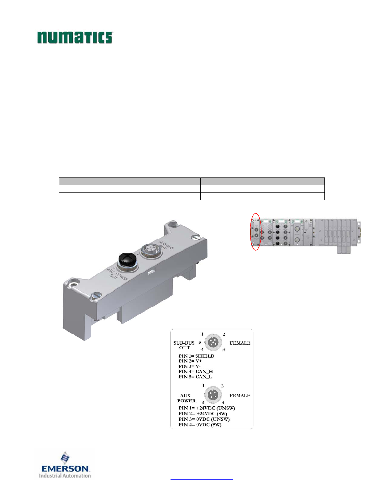
Sub-Bus OUT Module
Used only when distributing the Sub-Bus to another assembly is required.
SUB-BUS OUT - 5 pin M12 female communication connector.
o Used to distribute the Sub-Bus to the next Sub-Bus assembly.
o Carries 24 VDC power for electronics of the next module.
AUX. POWER OUT - 4 pin M12 female aux. power connector.
o Optional connection.
o Used as a convenience way to distribute the power connection to the next
Sub-Bus assembly.
Sub-Bus OUT Module with Din Rail Mounting 240-244
Sub-Bus OUT module without Din Rail Mounting 240-183
Description Replacement Part Number
TDG3EPTM1-1EN 05/09
Subject to change without notice
Page 39
www.numatics.com/g3
Page 41
G3SeriesEtherNet/IPTechnicalManual
SUB-BUS IN Modules
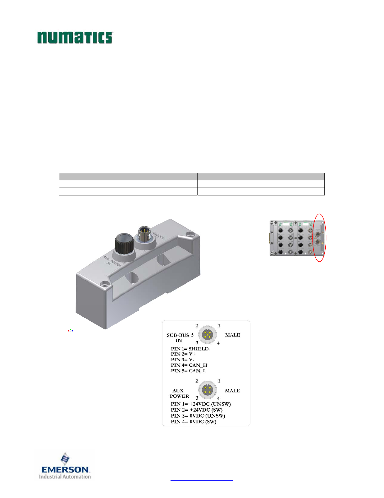
Used to distribute I/O assemblies that do not have valves
SUB-BUS IN - 5 pin M12 male communication connector.
AUX. POWER IN - 4 pin M12 male connector.
o Must be installed to the right of the I/O modules.
o Must be connected to the Sub-Bus Out connector of the previous assembly
o Carries 24 VDC power for electronics of module
o Aux power is required for Output modules. This connection also allows Output power to be
interrupted to all Output modules connected to this module.
o Aux. Power is optional for Inputs. Power from the SUN-BUS IN connection is used to power
sensors but can be augmented, if necessary, by adding additional power to this connector.
Description Part Number
Sub-Bus IN module with Din Rail Mounting 240-246
Sub-Bus IN module without Din Rail Mounting 240-185
TDG3EPTM1-1EN 05/09
Subject to change without notice
Page 40
www.numatics.com/g3
Page 42
G3SeriesEtherNet/IPTechnicalManual
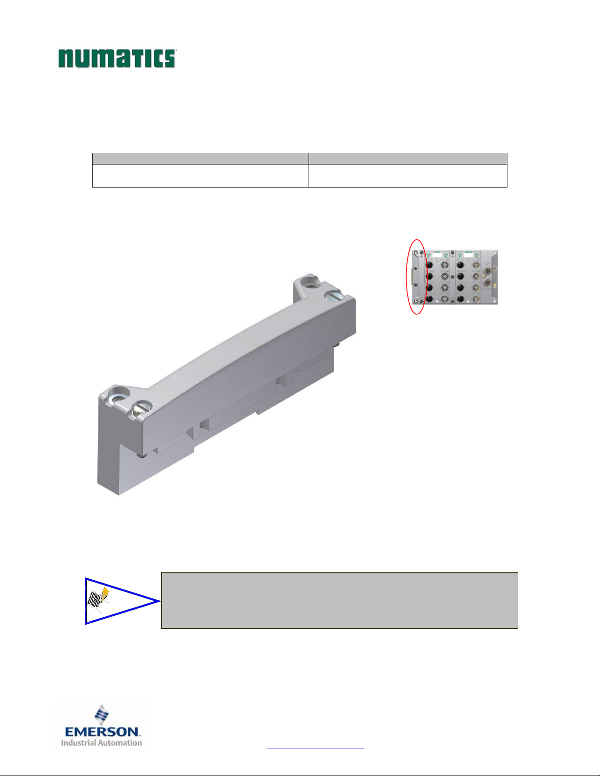
Terminator Module
Used to terminate SUB-BUS connections.
o Must be installed on the left side of the last Sub-Bus module.
Terminator Module with Din Rail Mounting 240-245
Terminator Module without Din Rail Mounting 240-184
NOTE!
Description Part Number
The terminator module is required to be installed in the G3 system for proper
operation
TDG3EPTM1-1EN 05/09
Subject to change without notice
Page 41
www.numatics.com/g3
Page 43
G3SeriesEtherNet/IPTechnicalManual
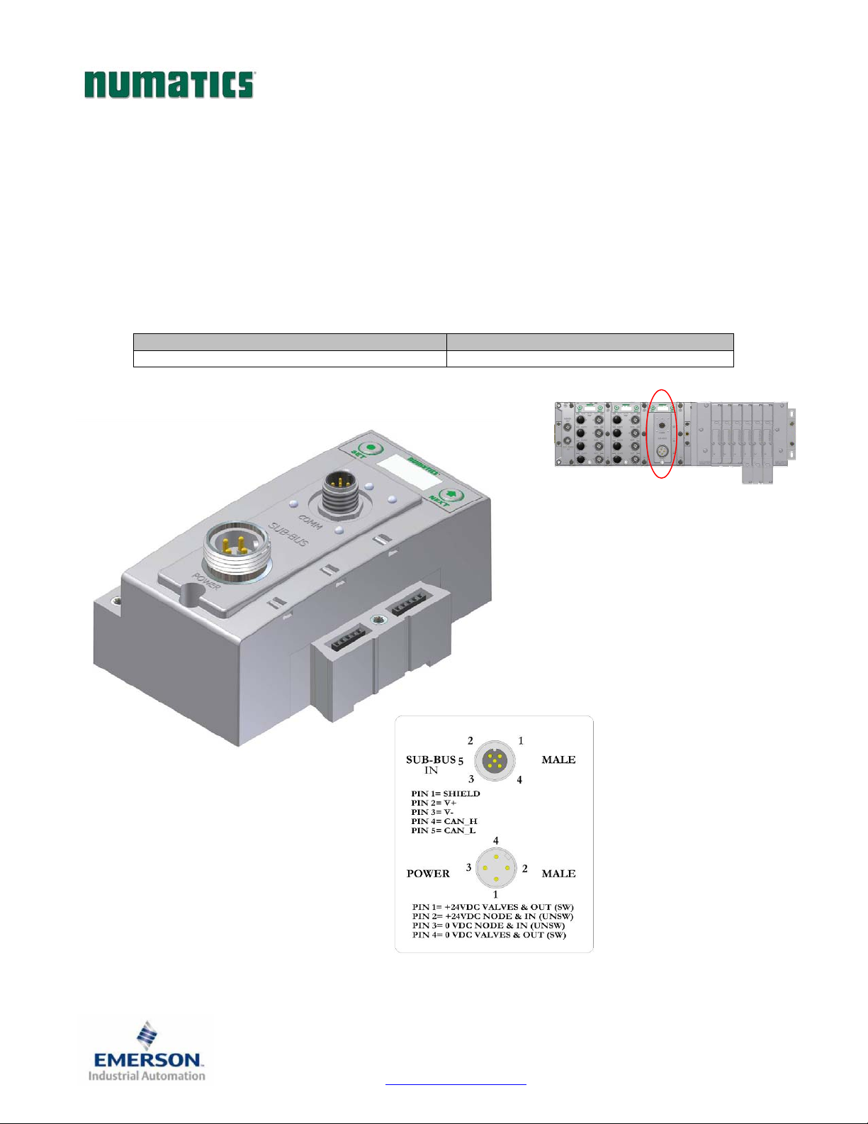
Sub-Bus Valve Module
COMM - 5 pin M12 male Sub-Bus input communication connector.
o Must be connected to the SUB-BUS OUT connector of the previous assembly
o Carries 24 VDC power for electronics of module
POWER - 4 pin MINI male power connector.
o Power is required for Outputs
Used to distribute Valves on the Sub-Bus.
o Can accepts discrete I/O module to allow a Sub-Bus Valve manifold with I/O
Description Part Number
Sub-Bus Valve Module 240-241
Digital I/O Modules
Page 42
TDG3EPTM1-1EN 05/09
Subject to change without notice
www.numatics.com/g3
Page 44
G3SeriesEtherNet/IPTechnicalManual
Digital I/O Module
Digital I/O Module Rules
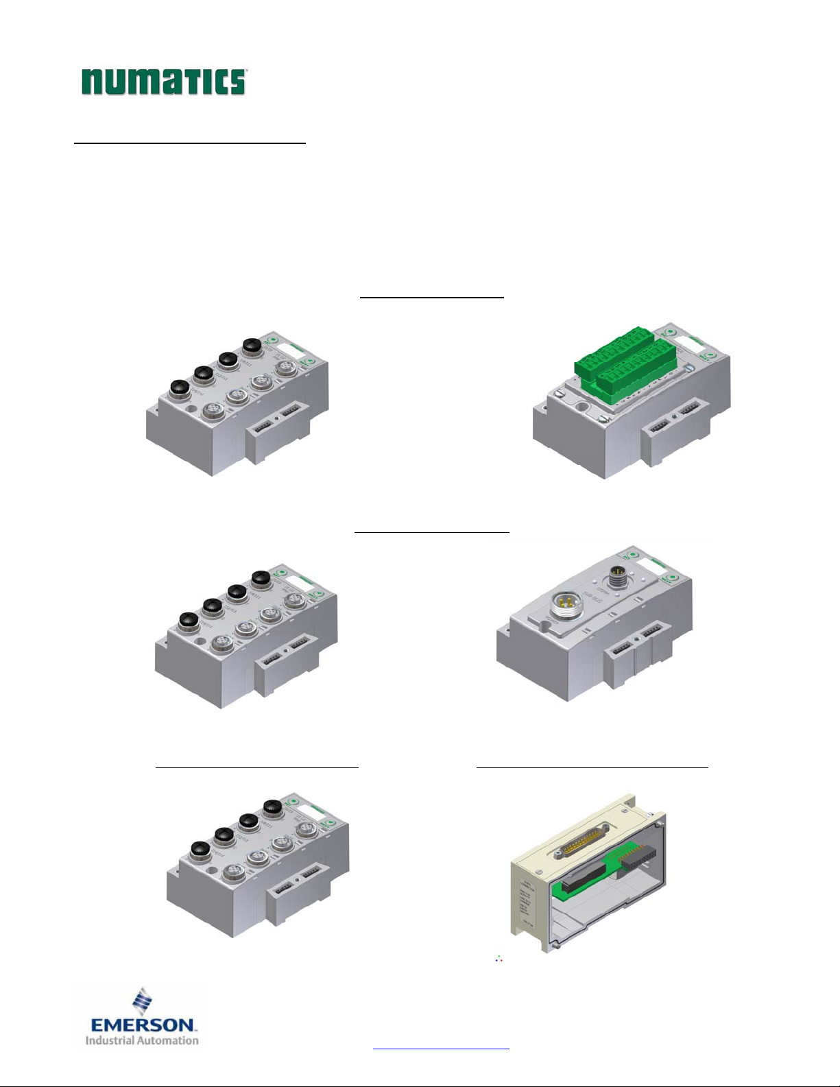
The maximum number of modules that can be used on the Discrete I/O side of the manifold is 16. These
modules can be centralized on the main fieldbus manifold, distributed or a combination of both. Modules can
be connected in any combination of inputs, outputs and specialty up to the physical limitation of 16 modules.
Input Module Types
Output Module Types
Input/Output Module Types Valve Side Output Module Types
TDG3EPTM1-1EN 05/09
Subject to change without notice
Page 43
www.numatics.com/g3
Page 45
V
G3SeriesEtherNet/IPTechnicalManual
I/O Module Descriptions and Menus
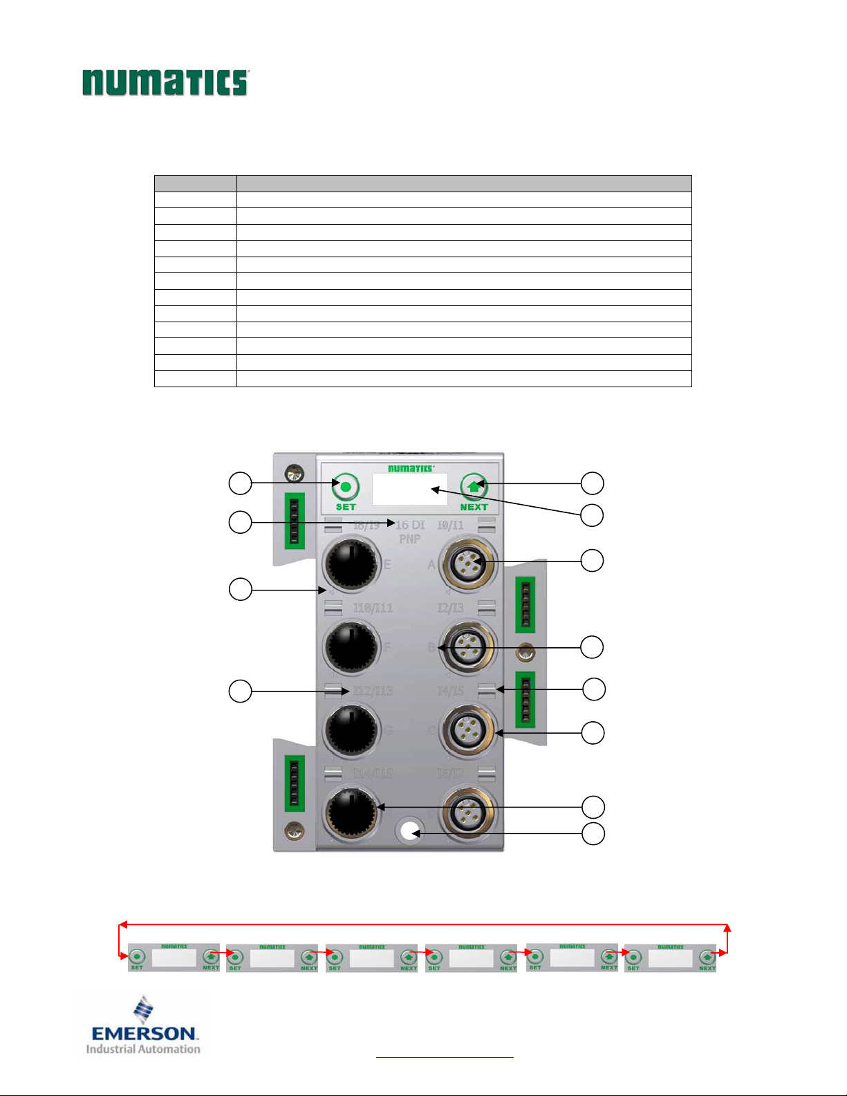
Detail No. Description
1 “Set” Button – used to navigate through user menus and set parameters
2 Module Function (I/O Type)
3 Alignment arrow for SPEEDCON connector
4 Bit Designation for I/O
5 “Next” Button – used to navigate through user menus and set parameters
6 Graphic Display
7 5 Pin M12 female I/O connector
8 Connector designation
9 Metal threads for SPEEDCON connector
10 Slot for text ID tags
11 Dust Cover
12 Mounting hole
Menu
1
2
3
4
5
6
7
8
10
9
11
12
IOMAPPING
DIAGBYTEXX
IOMAPPING
OUPUTBYTEXX
Page 44
DESCRIPTION
TDG3EPTM1-1EN 05/09
Subject to change without notice
www.numatics.com/g3
PARTNUMBER
240‐XXX
FIRMWARE
2.XXX
SET
BRIGHTNESS
Page 46
G3SeriesEtherNet/IPTechnicalManual
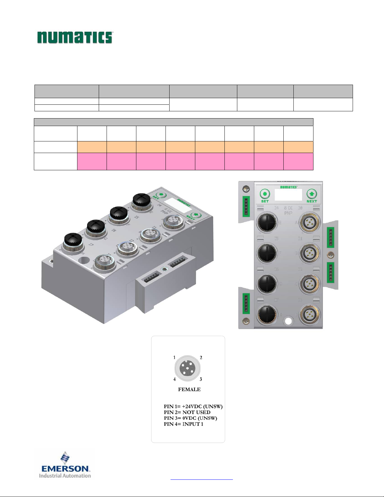
Digital Input Modules
One Digital Input per Connector – M12 Female Modules
Module
Part No.
240-206 NPN (Sinking)
240-210 PNP (Sourcing)
I/O Type Short Circuit Protection
YES – Visual YES – Optional 8
Input Mapping
BYTE Bit 7 Bit 6 Bit 5 Bit 4 Bit 3 Bit 2 Bit 1 Bit 0
X
(Required)
X+1
(Optional)
Input 7 Input 6 Input 5 Input 4 Input 3 Input 2 Input 1 Input 0
Conn. H
SCP
Status
Conn. G
SCP
Status
Conn. F
SCP
Status
Conn. E
SCP
Status
Conn. D
SCP
Status
Conn. C
Short Circuit
Protection Status Bits
SCP
Status
Conn. B
SCP
Status
Input Points
Conn. A
SCP
Status
TDG3EPTM1-1EN 05/09
Subject to change without notice
Page 45
www.numatics.com/g3
Page 47
G3SeriesEtherNet/IPTechnicalManual
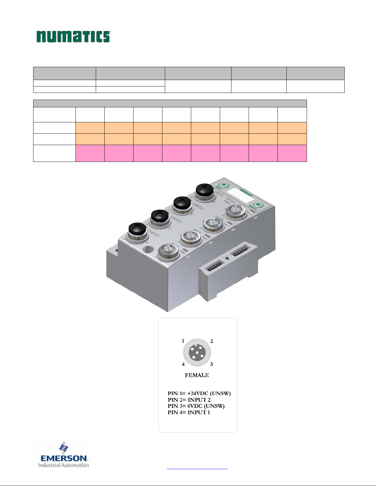
Two Digital Inputs per Connector – M12 Female Modules
Module
Part No.
240-209 NPN (Sinking)
240-205 PNP (Sourcing)
I/O Type Short Circuit Protection
YES – Visual YES – Optional 16
Input Mapping
BYTE Bit 7 Bit 6 Bit 5 Bit 4 Bit 3 Bit 2 Bit 1 Bit 0
X
(Required)
X+1
(Required)
X+2
(Optional)
Input 7 Input 6 Input 5 Input 4 Input 3 Input 2 Input 1 Input 0
Input 15 Input 14 Input 13 Input 12 Input 11 Input 10 Input 9 Input 8
Conn. H
SCP
Status
Conn. G
SCP
Status
Conn. F
SCP
Status
Conn. E
SCP
Status
Conn. D
SCP
Status
Short Circuit
Protection Status Bits
Conn. C
SCP
Status
Conn. B
SCP
Status
Input Points
Conn. A
SCP
Status
TDG3EPTM1-1EN 05/09
Subject to change without notice
Page 46
www.numatics.com/g3
Page 48
G3SeriesEtherNet/IPTechnicalManual
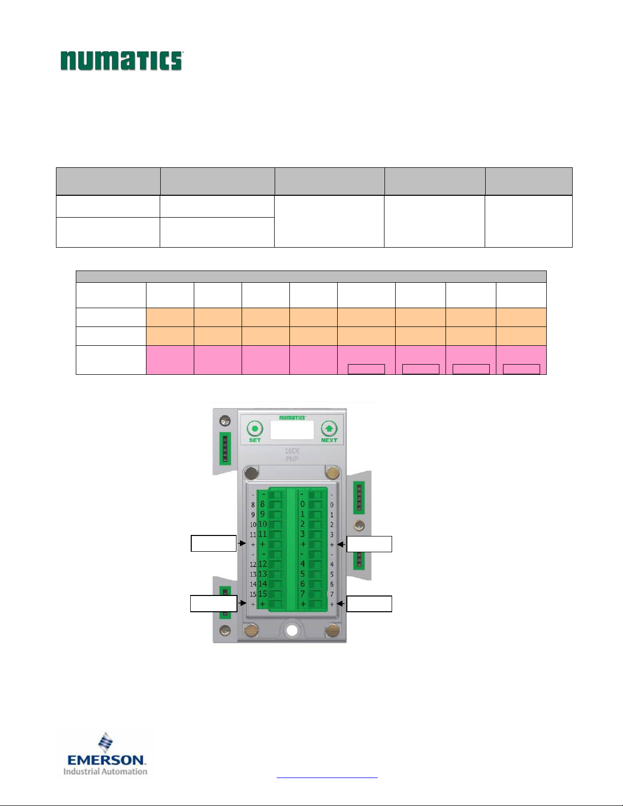
Sixteen Digital Inputs – Terminal Strip Modules
Specifications
- Wire Range: 12 to 24 AWG
- Strip Length: 7mm
- Tightening Torque: 0.5 Nm
Module
Part No.
240-203 PNP (Sourcing)
240-204 NPN (Sinking)
I/O Type Short Circuit Protection
YES
Visual and
Logical Status Bits
Input Mapping
BYTE Bit 7 Bit 6 Bit 5 Bit 4 Bit 3 Bit 2 Bit 1 Bit 0
X
(Required)
X+1
(Required)
X+2
(Optional)
Input 7 Input 6 Input 5 Input 4 Input 3 Input 2 Input 1 Input 0
Input 15 Input 14 Input 13 Input 12 Input 11 Input 10 Input 9 Input 8
Allocated
and
Reserved
Allocated
and
Reserved
Allocated
and
Reserved
Allocated
and
Reserved
SCP Status
1 = Fault
“+” No. 4
Short Circuit Protection
Status Bits
4 user enabled bits
monitor Short Circuits on
the four different +
voltage connections of
terminal strip
SCP Status
1 = Fault
“+” No. 3
SCP Status
1 = Fault
“+” No. 2
Input Points
16
SCP Status
1 = Fault
“+” No. 1
“+” No. 4
“+” No. 3
“+” No. 1
“+” No. 2
TDG3EPTM1-1EN 05/09
Subject to change without notice
Page 47
www.numatics.com/g3
Page 49
G3SeriesEtherNet/IPTechnicalManual
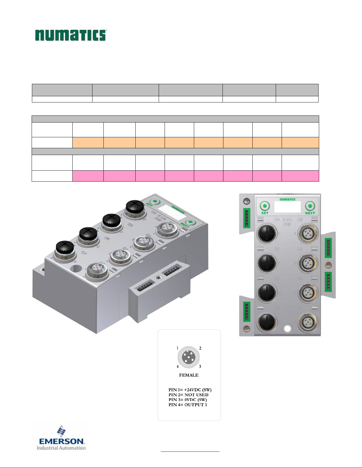
Digital Output Modules
One Digital Output per Connector - M12 Female Modules
Module
Part No.
240-208 PNP (Sourcing) YES – Visual YES (8) – Optional 8
I/O Type Short Circuit Protection
Output Mapping
BYTE Bit 7 Bit 6 Bit 5 Bit 4 Bit 3 Bit 2 Bit 1 Bit 0
X
(Required)
Output 7 Output 6 Output 5 Output 4 Output 3 Output 2 Output 1 Output 0
Input Mapping
BYTE Bit 7 Bit 6 Bit 5 Bit 4 Bit 3 Bit 2 Bit 1 Bit 0
Short Circuit
Protection Status Bits
Output Points
X
(Optional)
Output 7
Status
Output 6
Status
Output 5
Status
Output 4
Status
Output 3
Status
Output 2
Status
Output 1
Status
Output 0
Status
TDG3EPTM1-1EN 05/09
Subject to change without notice
Page 48
www.numatics.com/g3
Page 50
G3SeriesEtherNet/IPTechnicalManual
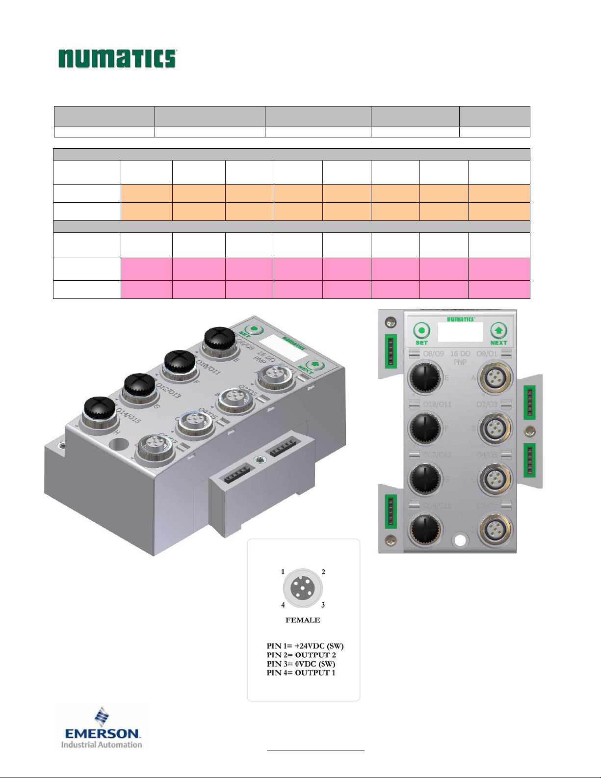
Two Digital Outputs per Connector - M12 Female Modules
Module
Part No.
I/O Type Short Circuit Protection
240-207 PNP (Sourcing) YES – Visual YES (8) – Optional 16
Output Mapping
BYTE Bit 7 Bit 6 Bit 5 Bit 4 Bit 3 Bit 2 Bit 1 Bit 0
X
(Required)
X+1
(Required)
Output 7 Output 6 Output 5 Output 4 Output 3 Output 2 Output 1 Output 0
Output 15 Output 14 Output 13 Output 12 Output 11 Output 10 Output 9 Output 8
Input Mapping
BYTE Bit 7 Bit 6 Bit 5 Bit 4 Bit 3 Bit 2 Bit 1 Bit 0
Short Circuit
Protection Status Bits
Output Points
X
(Optional)
X+1
(Optional)
Output 7
Status
Output 15
Status
Output 6
Status
Output 14
Status
Output 5
Status
Output 13
Status
Output 4
Status
Output 12
Status
Output 3
Status
Output 11
Status
Output 2
Status
Output 10
Status
Output 1
Status
Output 9
Status
Output 0
Status
Output 8
Status
TDG3EPTM1-1EN 05/09
Subject to change without notice
Page 49
www.numatics.com/g3
Page 51
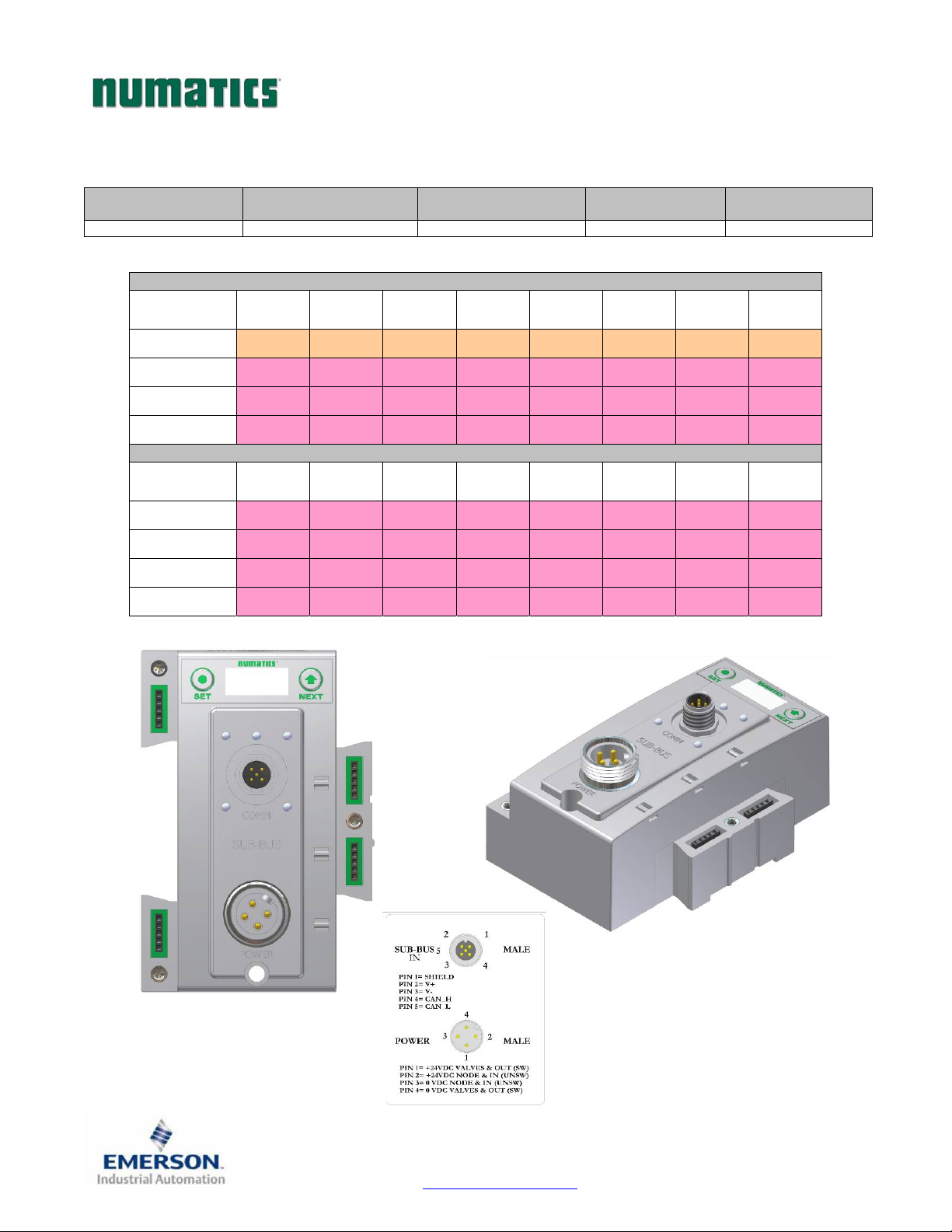
G3SeriesEtherNet/IPTechnicalManual
Sub-Bus Valve Module
Used to control a distributed valve manifold through the Sub-Bus. See page 42 for more information.
Module
Part No.
I/O Type Short Circuit Protection
240-241 NPN (Sinking) YES – Visual YES (32) – Optional 32
Output Mapping
BYTE Bit 7 Bit 6 Bit 5 Bit 4 Bit 3 Bit 2 Bit 1 Bit 0
X
(Required)
X+1
(Optional)
X+2
(Optional)
X+3
(Optional)
Valve Coil
No. 7
Valve Coil
No. 15
Valve Coil
No. 23
Valve Coil
No. 31
Valve Coil
No. 6
Valve Coil
No. 14
Valve Coil
No. 22
Valve Coil
No. 30
Valve Coil
No. 5
Valve Coil
No. 13
Valve Coil
No. 21
Valve Coil
No. 29
Valve Coil
No. 4
Valve Coil
No. 12
Valve Coil
No. 20
Valve Coil
No. 28
Valve Coil
No. 3
Valve Coil
No. 11
Valve Coil
No. 19
Valve Coil
No. 27
Input Mapping
BYTE Bit 7 Bit 6 Bit 5 Bit 4 Bit 3 Bit 2 Bit 1 Bit 0
X
(Optional)
X+1
(Optional)
X+2
(Optional)
X+3
(Optional)
Coil 7
Status
Coil 15
Status
Coil 23
Status
Coil 31
Status
Coil 6
Status
Coil 14
Status
Coil 22
Status
Coil 30
Status
Coil 5
Status
Coil 13
Status
Coil 21
Status
Coil 29
Status
Coil 4
Status
Coil 12
Status
Coil 20
Status
Coil 28
Status
Coil 3
Status
Coil 11
Status
Coil 19
Status
Coil 27
Status
Short Circuit
Protection Status Bits
Valve Coil
No. 2
Valve Coil
No. 10
Valve Coil
No. 18
Valve Coil
No. 26
Coil 2
Status
Coil 10
Status
Coil 18
Status
Coil 26
Status
Valve Coil
No. 1
Valve Coil
No. 9
Valve Coil
No. 17
Valve Coil
No. 25
Coil 1
Status
Coil 9
Status
Coil 17
Status
Coil 25
Status
Output Points
Valve Coil
No. 0
Valve Coil
No. 8
Valve Coil
No. 16
Valve Coil
No. 24
Coil 0
Status
Coil 8
Status
Coil 16
Status
Coil 24
Status
TDG3EPTM1-1EN 05/09
Subject to change without notice
Page 50
www.numatics.com/g3
Page 52
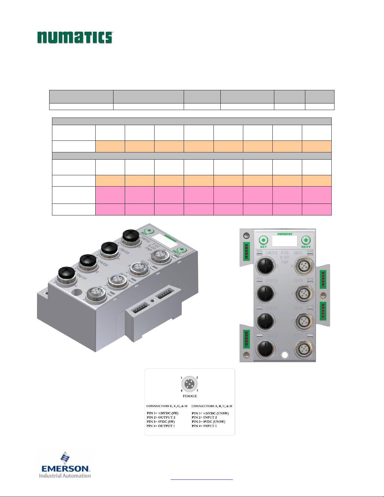
G3SeriesEtherNet/IPTechnicalManual
Digital Input/Output Modules
Two Digital I/O per Connector - 12mm Female Modules
…
Module Part No. I/O Type
240-211 PNP (Sourcing) YES – Visual YES (8) – Optional 8 8
Short Circuit
Protection
Output Mapping
BYTE Bit 7 Bit 6 Bit 5 Bit 4 Bit 3 Bit 2 Bit 1 Bit 0
X
(Required)
Output 7 Output 6 Output 5 Output 4 Output 3 Output 2 Output 1 Output 0
Input Mapping
BYTE Bit 7 Bit 6 Bit 5 Bit 4 Bit 3 Bit 2 Bit 1 Bit 0
X
(Required)
X+1
(Optional)
X+2
(Optional)
Input 7 Input 6 Input 5 Input 4 Input 3 Input 2 Input 1 Input 0
Allocated
and
Reserved
Output 7
Status Bit
Allocated
and
Reserved
Output 6
Status Bit
Allocated
and
Reserved
Output 5
Status Bit
Allocated
and
Reserved
Output 4
Status Bit
Short Circuit
Protection Status Bits
Conn. D
SCP
Status
Output 3
Status Bit
Conn. C
SCP
Status
Output 2
Status Bit
Output
Points
Conn. B
SCP
Status
Output 1
Status Bit
Input
Points
Conn. A
SCP
Status
Output 0
Status Bit
TDG3EPTM1-1EN 05/09
Subject to change without notice
Page 51
www.numatics.com/g3
Page 53

G3SeriesEtherNet/IPTechnicalManual
Valve Side Digital Output Modules
The valve side output module is used to distribute available valve side output points (i.e. when valves are
located away from the rest of the electronics). These modules go to the right of the G3 valve aqdapter. The 16
bit output module utilizes the last 16 output bits on the valve side of the manifold (bits 16-31).
Sixteen Outputs per Connector - Sub-D 25 Pin Female Module
Module
Part No.
239-1713 NPN (Sinking) Yes 16 – Optional 16 Narrow
I/O Type
Short Circuit
Protection
Internal Status
Bits
Output Points Module Size
TDG3EPTM1-1EN 05/09
Subject to change without notice
Page 52
www.numatics.com/g3
Page 54

G3SeriesEtherNet/IPTechnicalManual
Analog I/O Modules
Analog I/O Module Rules
The analog I/O modules follow the same rules as the digital I/O modules. The maximum total number of
modules on the Sub-Bus is 16. The analog boards allow the user to control devices using an analog signal.
The analog modules also allow the user to relay analog information from input devices. These modules are
available in two analog signal types: 0-10 V and 4-20 mA. These two signal types are offered in two different
I/O configurations: 2 analog input channels/ 2 analog outputs channels and 4 analog input channels.
Four I/O - 12mm Female Modules
Specifications
- Input Resolution: 16 bit (65,536 Counts),
- Output Resolution: 16 bit (65,536 Counts)
- Settling Time: 3 ms Max
- Absolute Precision: ≤ 1.0% of Signal
- Voltage Input Impedance: 0-10VDC – 40K Ohms
- Current Input Impedance: 250 Ohms
- Input Cutoff Frequency: 100 Hz
Module
Part No.
240-212 0 - 10V 4 0
240-213 0 - 10V 2 2
240-214 4 - 20mA 4 0
240-215 4 - 20mA 2 2
Signal Type Input Points Output Points Short Circuit Protection
Yes
TDG3EPTM1-1EN 05/09
Subject to change without notice
Page 53
www.numatics.com/g3
Page 55
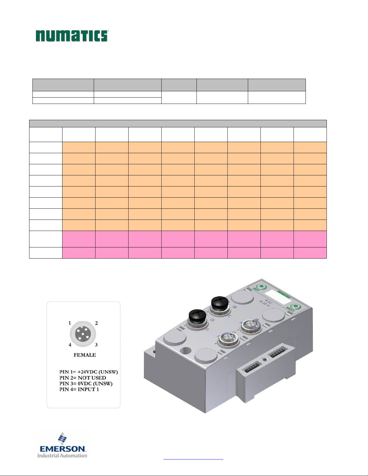
G3SeriesEtherNet/IPTechnicalManual
One Analog Input per Connector – M12 Female Modules
Module
Part No.
Signal Type
240-212 0-10 VDC
240-214 4-20 mA
Short Circuit
Protection
Short Circuit
Protection Status Bits
Input Points
YES – Visual YES (4) – Optional 4
Input Mapping
BYTE Bit 7 Bit 6 Bit 5 Bit 4 Bit 3 Bit 2 Bit 1 Bit 0
X
(Required)
X+1
(Required)
X+2
(Required)
X+3
(Required)
X+4
(Required)
X+5
(Required)
X+6
(Required)
X+7
(Required)
X+8
(Optional)
X+9
(Optional)
Input No. 1 Input No. 1 Input No. 1 Input No. 1 Input No. 1 Input No. 1 Input No. 1
Input No. 1
(MSB)
Input No. 2 Input No. 2 Input No. 2 Input No. 2 Input No. 2 Input No. 2 Input No. 2
Input No. 2
(MSB)
Input No. 3 Input No. 3 Input No. 3 Input No. 3 Input No. 3 Input No. 3 Input No. 3
Input No. 3
(MSB)
Input No. 4 Input No. 4 Input No. 4 Input No. 4 Input No. 4 Input No. 4 Input No. 4
Input No. 4
(MSB)
Allocated
and
Reserved
High Alarm
for Conn. D
Input No. 1 Input No. 1 Input No. 1 Input No. 1 Input No. 1 Input No. 1 Input No. 1
Input No. 2 Input No. 2 Input No. 2 Input No. 2 Input No. 2 Input No. 2 Input No. 2
Input No. 3 Input No. 3 Input No. 3 Input No. 3 Input No. 3 Input No. 3 Input No. 3
Input No. 4 Input No. 4 Input No. 4 Input No. 4 Input No. 4 Input No. 4 Input No. 4
Allocated
and
Reserved
Low Alarm
for Conn. D
Allocated
and
Reserved
High Alarm
for Conn. C
Allocated
and
Reserved
Low Alarm
for Conn. C
Power Status
for Conn. D
High Alarm
for Conn. B
Power Status
for Conn. C
Low Alarm
for Conn. B
Power Status
for Conn. B
High Alarm
for Conn. A
Input No. 1
(LSB)
Input No. 2
(LSB)
Input No. 3
(LSB)
Input No. 4
(LSB)
Power Status
for Conn. A
Low Alarm
for Conn. A
TDG3EPTM1-1EN 05/09
Subject to change without notice
Page 54
www.numatics.com/g3
Page 56
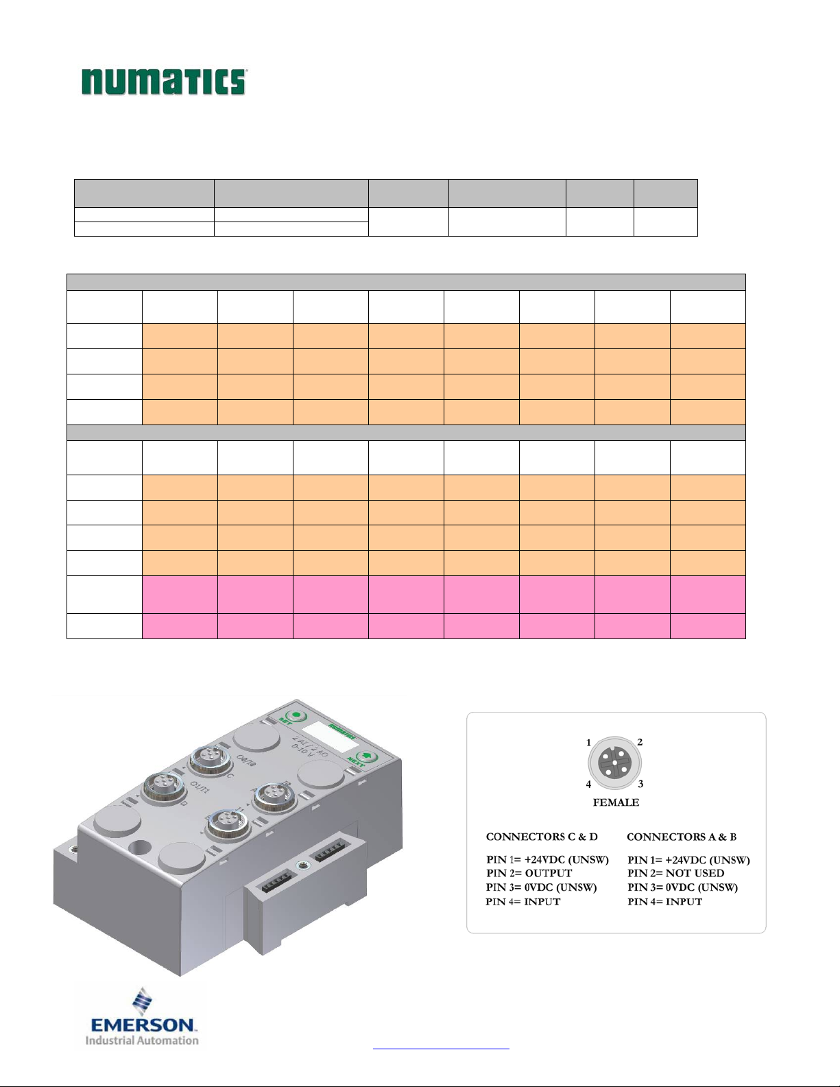
G3SeriesEtherNet/IPTechnicalManual
One Analog I/O per Connector – M12 Female Modules
Module
Part No.
Signal Type
240-213 0-10 VDC
240-215 4-20 mA
Short Circuit
Protection
Short Circuit
Protection Status Bits
Output
Points
Input
Points
YES – Visual YES (4) – Optional 2 2
Output Mapping
BYTE Bit 7 Bit 6 Bit 5 Bit 4 Bit 3 Bit 2 Bit 1 Bit 0
X
(Required)
X+1
(Required)
X+2
(Required)
X+3
(Required)
Output No. 1 Output No. 1 Output No. 1 Output No. 1 Output No. 1 Output No. 1 Output No. 1 Output No.
Output No.
1 (MSB)
Output No. 2 Output No. 2 Output No. 2 Output No. 2 Output No. 2 Output No. 2 Output No. 2 Output No.
Output No.
2 (MSB)
Output No. 1 Output No. 1 Output No. 1 Output No. 1 Output No. 1 Output No. 1 Output No.
Output No. 2 Output No. 2 Output No. 2 Output No. 2 Output No. 2 Output No. 2 Output No.
Input Mapping
BYTE Bit 7 Bit 6 Bit 5 Bit 4 Bit 3 Bit 2 Bit 1 Bit 0
X
(Required)
X+1
(Required)
X+2
(Required)
X+3
(Required)
X+8
(Optional)
X+9
(Optional)
Input No. 1 Input No. 1 Input No. 1 Input No. 1 Input No. 1 Input No. 1 Input No. 1
Input No. 1
(MSB)
Input No. 2 Input No. 2 Input No. 2 Input No. 2 Input No. 2 Input No. 2 Input No. 2
Input No. 2
(MSB)
Allocated
and
Reserved
High Alarm
for Conn. D
Input No. 1 Input No. 1 Input No. 1 Input No. 1 Input No. 1 Input No. 1 Input No. 1
Input No. 2 Input No. 2 Input No. 2 Input No. 2 Input No. 2 Input No. 2 Input No. 2
Allocated
and
Reserved
Low Alarm
for Conn. D
Allocated
and
Reserved
High Alarm
for Conn. C
Allocated
and
Reserved
Low Alarm
for Conn. C
Power Status
for Conn. D
High Alarm
for Conn. B
Power Status
for Conn. C
Low Alarm
for Conn. B
Power Status
for Conn. B
High Alarm
for Conn. A
1 (LSB)
1
2 (LSB)
2
Input No. 1
(LSB)
Input No. 2
(LSB)
Power Status
for Conn. A
Low Alarm
for Conn. A
TDG3EPTM1-1EN 05/09
Subject to change without notice
Page 55
www.numatics.com/g3
Page 57
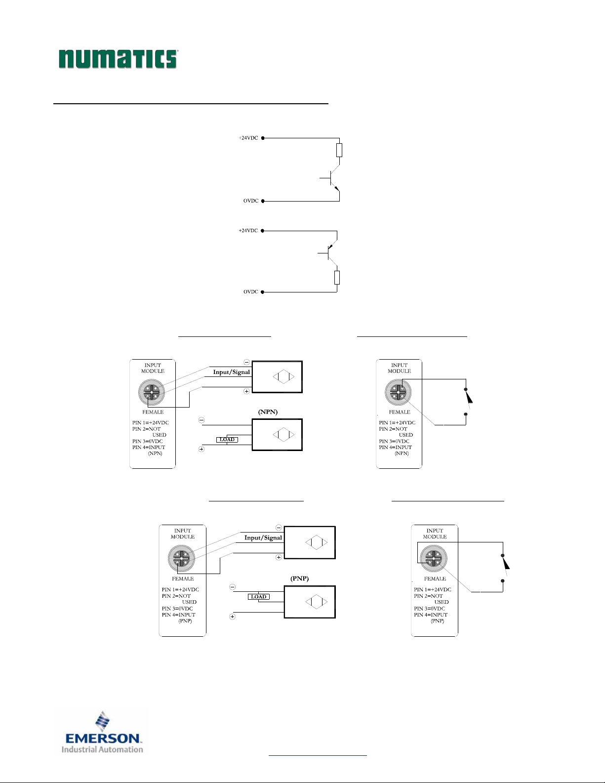
G3SeriesEtherNet/IPTechnicalManual
I/O Module(s) Wiring Diagrams
NPN/PNP Definitions
NPN Descriptions
Sinking
Switching Negative
Positive Common
PNP Descriptions
Sourcing
Switching Positive
Negative Common
NPN (Sinking) Input Connection
2
1
Electric Sensor Type
3
4
PNP (Sourcing) Input Connection
Electric Sensor Type
LOAD
LOAD
Mechanical Sensor Type
3
2
4
1
Mechanical Sensor Type
2
3
4
1
2
3
4
1
TDG3EPTM1-1EN 05/09
Subject to change without notice
Page 56
www.numatics.com/g3
Page 58
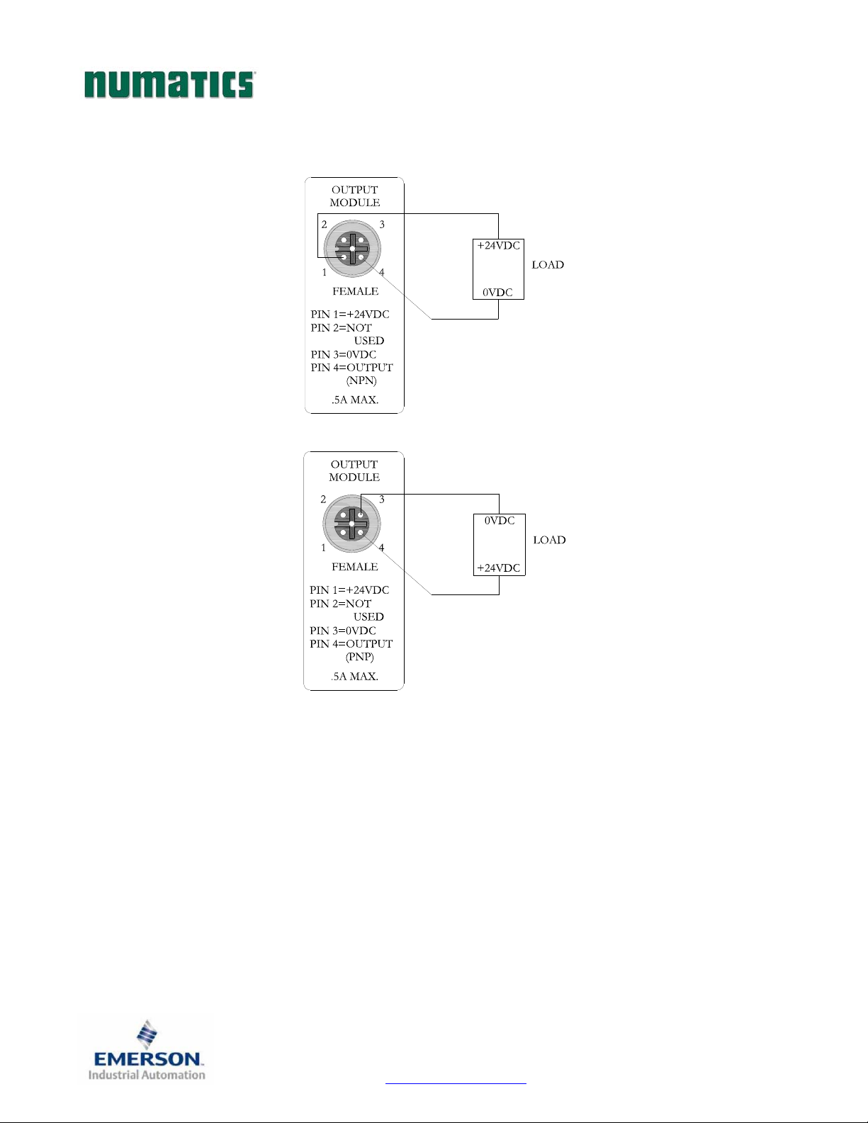
G3SeriesEtherNet/IPTechnicalManual
I/O Module(s) Wiring Diagrams Continued
NPN (Sinking) Output Connection
PNP (Sourcing) Output Connection
TDG3EPTM1-1EN 05/09
Subject to change without notice
Page 57
www.numatics.com/g3
Page 59

G3SeriesEtherNet/IPTechnicalManual
EtherNet/IPTM Configuration and Mapping
EDS File
The EDS file contains configuration information about the Numatics valve manifold. EDS files are available
on the Numatics, Inc., website at www.numatics.com/fieldbus
.
TDG3EPTM1-1EN 05/09
Subject to change without notice
Page 58
www.numatics.com/g3
Page 60
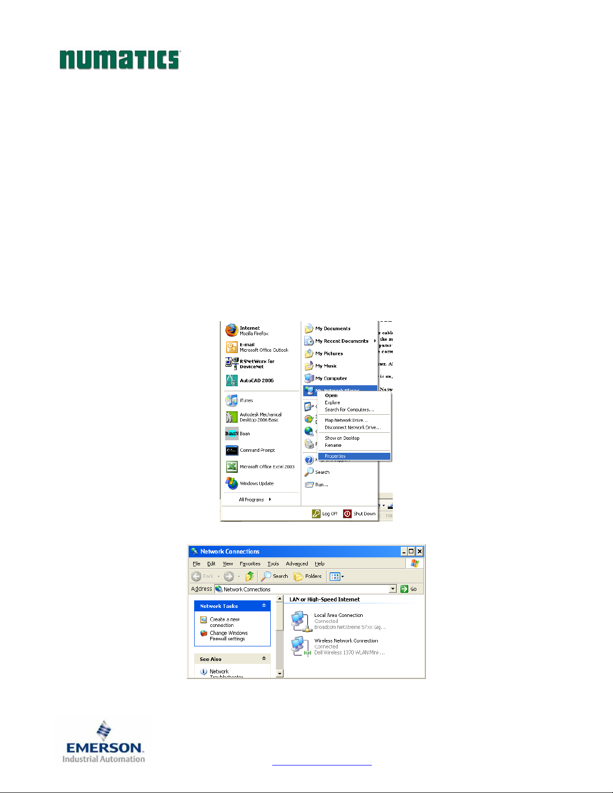
G3SeriesEtherNet/IPTechnicalManual
Connecting to a G3 Series EtherNet/IPTM Node
This section will discuss how to connect a computer to a G3 Series EtherNet/IP
ways to complete this task, so only two will be discussed. All computer commands are shown in Windows XP.
1. Connect a 24VDC power supply to the valve manifold. The power pin-out can be found on the side of
the EtherNet/IP
the “+24VDC (NODE & INPUTS)” pin to power the node.)
2. Connect a crossover cable directly from the manifold to the computer -OR- Connect a straight-
through cable from the manifold to a router, hub, or switch. Next, connect a straight-through cable
from the computer to the router, hub, or switch. (Network lights should appear on the router, hub, or
switch if the correct cables are used).
3. Turn on the computer. Also, make sure the manifold and the router, hub, or switch has power.
4. To communicate with an EtherNet/IP
To start this process, left click on the “Start” button.
5. Right click on “My Network Places” and then scroll down to “Properties”. Left click on “Properties”.
6. The “Network Connections” window will open. Right click on “Local Area Connection”.
TM
node or on page 12 of this document. (Note: 24VDC only needs to be applied to
TM
manifold the IP address of your computer must be known.
TM
node. There are multiple
TDG3EPTM1-1EN 05/09
Subject to change without notice
Page 59
www.numatics.com/g3
Page 61
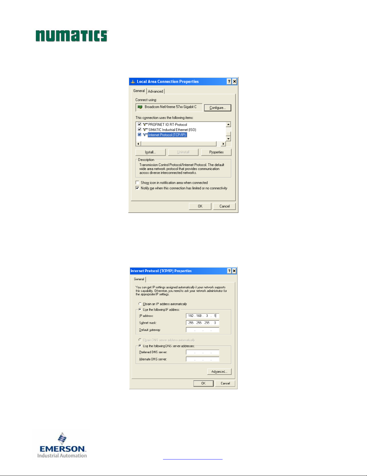
G3SeriesEtherNet/IPTechnicalManual
7. The “Local Area Connection Properties” window will now open. Scroll down in the box labeled, “This
connection uses the following items”. Locate the “Internet Protocol (TCP/IP)” option and highlight
it.
8. Left click on the “Properties” button. The “Internet Protocol (TCP/IP) Properties” window will
open. Choose the option marked “Use the following IP address” and type in an IP address that has
the same first three octets as the address that you will set the manifold to. For the last octet you may
choose any number from 0-255, just make sure that it is not the same number as the IP address that
the manifold will have. Make sure your subnet mask is set to “255.255.255.0” (this value can be
changed, but this value will be used for demonstration purposes).
9. Left click “OK” in the “Internet Protocol (TCP/IP) Properties” and “Local Area Connection”
windows for the changes to take effect on the computer. Close out of any open windows.
TDG3EPTM1-1EN 05/09
Subject to change without notice
Page 60
www.numatics.com/g3
Page 62
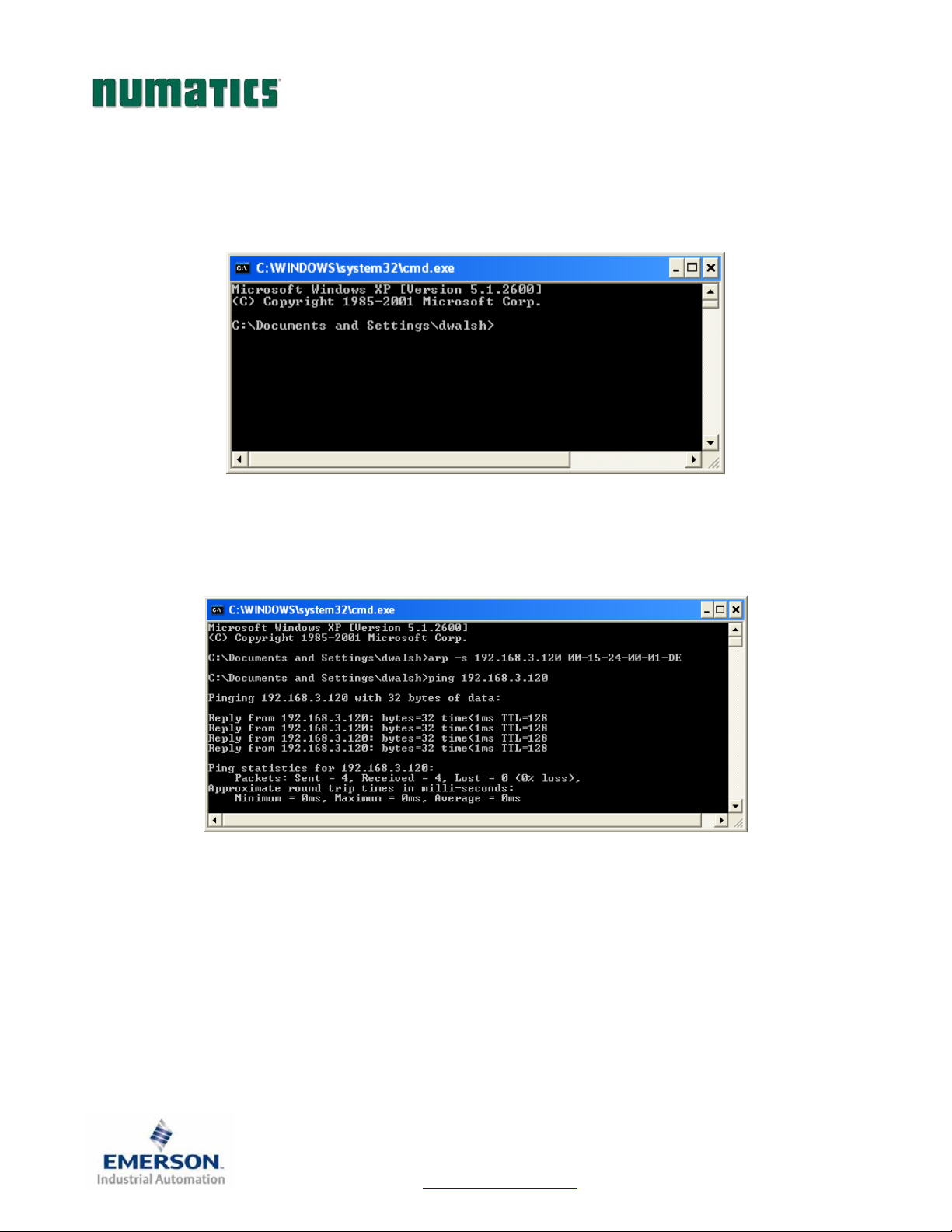
G3SeriesEtherNet/IPTechnicalManual
10. Once the IP address for the computer is known, you can set the IP address of the Numatics manifold
using one of the methods described on page 67 .
11. Left click on “Run”. This will open up the “Run” window.
12. Type “cmd” on the command line and left click “OK”. The command prompt will open.
13. Type, “Ping, and then the IP address that the manifold is set to, you can view the address on the
graphical display. For example, if the IP address is 192.168.3.120, “ping 192.168.3.120” would be typed.
You will get a message stating, “Reply from 192.168.3.120: bytes=32 time<1ms TTL=128”, if the
manifold responds.
TDG3EPTM1-1EN 05/09
Subject to change without notice
Page 61
www.numatics.com/g3
Page 63

G3SeriesEtherNet/IPTechnicalManual
14. Open a web browser on the computer and type in the IP address of the manifold.
Ex. http://192.168.3.120
15. You have successfully connected a computer to a Numatics EtherNet/IP
TM
manifold.
TDG3EPTM1-1EN 05/09
Subject to change without notice
Page 62
www.numatics.com/g3
Page 64

G3SeriesEtherNet/IPTechnicalManual
Using the Functionality of the G3 Series EtherNet/IPTM Web Server
This section will discuss the functionality of the built in Ethernet server. Every Numatics EtherNet/IP
this feature. Through this server you can configure the node, force I/O, check diagnostics, etc. Each
Numatics’ web page will be explained.
Home
To get to the Numatics “Home” page, open a web browser. In the URL line, type in the IP address of the
manifold and press “Enter”. The Numatics “Home” page will appear. This page shows a picture of the
Numatics EtherNet/IP
server.
TM
nodes and a manifold. From this page, the user can navigate the entire built-in web
TM
has
NOTE!
The 1st three octets of the IP address of the computer MUST match the
IP address of the node.
TDG3EPTM1-1EN 05/09
Subject to change without notice
Page 63
www.numatics.com/g3
Page 65

G3SeriesEtherNet/IPTechnicalManual
Node Configuration
The “Node Configuration” window can be used to control different parameters within the manifold. These
parameters include, “IP Address”, “Subnet Mask”, “Gateway Address”, “SMTP Server”, “DHCP/BOOTP
enabled”, “MAC Address”, and “COMM Fault/Idle Mode”. “DHCP/BOOTP enabled” is controlled by a
single check mark box. “COMM Fault/Idle Mode” has two options that can be chosen: “Hold last Output
State” and “Turn OFF All Outputs”.
Once the changes have been made, left click on the “Update Configuration” button. The “Configuration
Successfully Updated” window will appear. The Ethernet/IP
user may cycle power to enable the new configuration.
TM
node will reset in a few seconds, or the
TDG3EPTM1-1EN 05/09
Subject to change without notice
Page 64
www.numatics.com/g3
Page 66

G3SeriesEtherNet/IPTechnicalManual
I/O Force and Test
The “I/O Force and Test” window allows the user to test the outputs and inputs of the manifold. A Safety
Warning will appear telling the user to shut off the air supply to the valve manifold. Once the air is shut off, left
click on “Accept”.
The “Force Outputs and View Inputs” window will open. This window lets the user turn on outputs and
monitor the status of inputs that are connected to the manifold. Use the drop box to choose which I/O word
to control/monitor. Output forces can be applied using either the check boxes or “Output Byte Decimal
Value”. Left click on “Send I/O data” to force the outputs on/monitor the inputs.
TDG3EPTM1-1EN 05/09
Subject to change without notice
Page 65
www.numatics.com/g3
Page 67

G3SeriesEtherNet/IPTechnicalManual
Diagnostics
The “Diagnostics” window allows the user to monitor different values. These values include, “MAC Address”,
“Serial Number”, “Firmware Revision”, and “Valve Diagnostic Table”. The “Valve Diagnostic Table” enables
the user to check the status of the valve side outputs.
Numatics.com
The “Numatics.com” tab is a quick link to Numatics’ website. The computer must have internet access
for this tab to be functional.
TDG3EPTM1-1EN 05/09
Subject to change without notice
Page 66
www.numatics.com/g3
Page 68
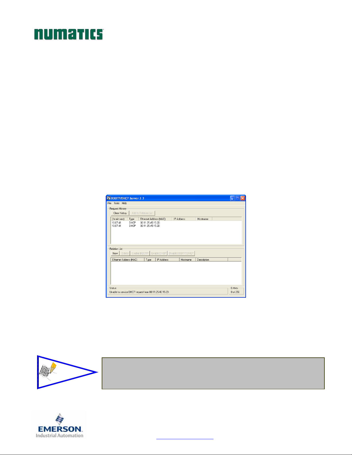
G3SeriesEtherNet/IPTechnicalManual
IP Address Configuration
The IP address of the Numatics G3 EtherNet/IP
DHCP/BOOTP
Integrated Web Page Configuration
Manual Configuration via DIP Switch
Graphical display
DHCP / BOOTP
The node is shipped from the factory with the DHCP/BOOTP feature enabled. This allows a DHCP server to
automatically set the IP address to the node when connected to the network, or a BOOTP server to establish
communication to the node and set the IP address. These addressing methods require that the unique MAC
ADDRESS of the node is known. The MAC ADDRESS is displayed on the graphical display of the node. It
will be different for every node. When DHCP/BOOTP is enabled and a DHCP server is found, the IP
address, Subnet mask, and gateway are automatically configured by the DHCP server.
The DHCP/BOOTP setting can be enabled or disabled via the nodes integrated web server or graphical
display.
™
node may be configured via several different methods:
If the optional MCM module is installed, for the DHCP/BOOTP feature is
NOTE!
Page 67
disabled.
TDG3EPTM1-1EN 05/09
Subject to change without notice
www.numatics.com/g3
Page 69

G3SeriesEtherNet/IPTechnicalManual
Integrated Web Page Configuration
The Numatics EtherNet/IP
web browser program. With the IP Address, the “Node Configuration” page for the node can be called up and
the configuration parameters updated. Please note that the PC, where the web browser is installed, must be
correctly configured for operation with the appropriate network IP ranges and Subnet settings that match the
EtherNet/IP
!
Below is a representation of the “Node Configuration” page which is stored in the EtherNet/IP
IP address, Subnet Mask, Gateway Address, SMTP server address and DHCP/BOOTP enabled
can all be configured from this page. These parameters will be programmed in the node’s non-volatile FLASH
memory once “Update Configuration” is clicked, and power to the node is cycled.
™
node.
™
node has an integrated web server. This server can be accessed via any standard
Consult appropriate personnel before changing your computer’s network
settings and always record previous settings for later reversal before
attempting changes.
™
node.
selections
The Ethernet/IPTM node will reset in a few seconds, or the user may cycle
!
power to enable the new configuration.
TDG3EPTM1-1EN 05/09
Subject to change without notice
Page 68
www.numatics.com/g3
Page 70

G3SeriesEtherNet/IPTechnicalManual
Manual Configuration via DIP Switch
Please see page 35 for Manual Configuration Module information and settings.
Graphic Display
Please see page 21 for graphical display settings
TDG3EPTM1-1EN 05/09
Subject to change without notice
Page 69
www.numatics.com/g3
Page 71
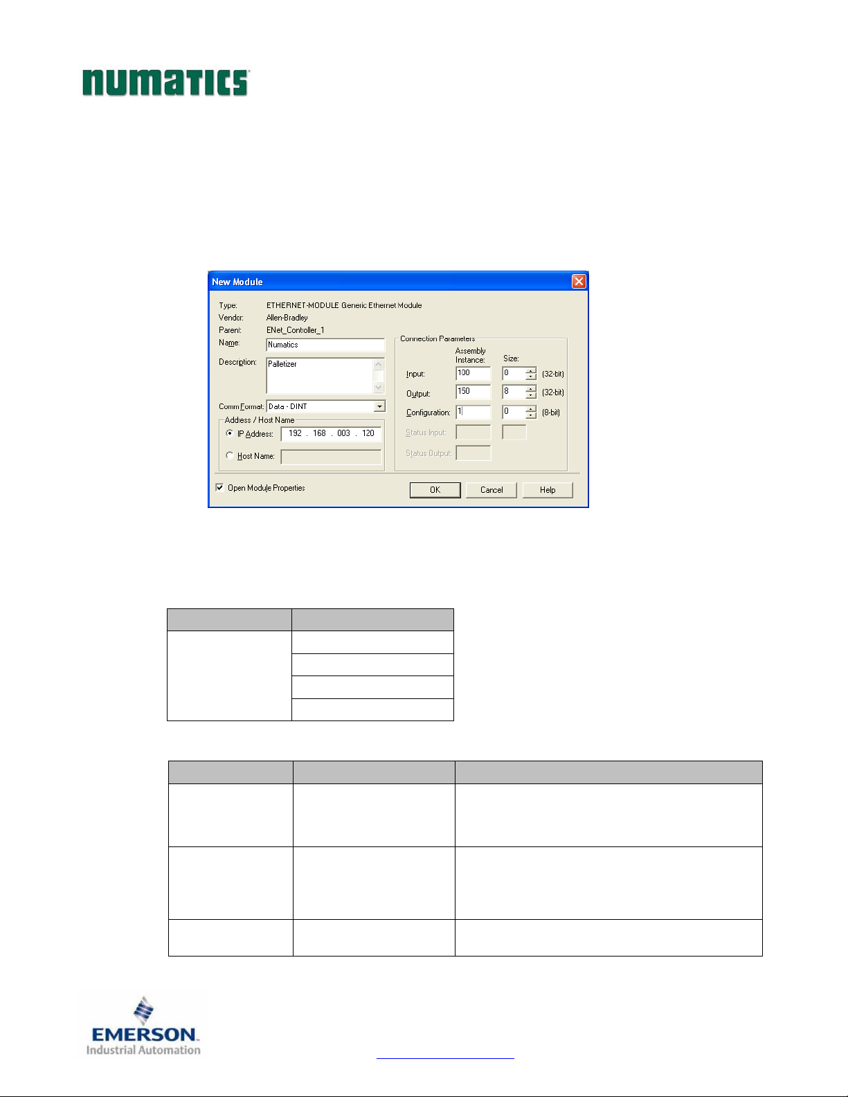
G3SeriesEtherNet/IPTechnicalManual
Configuration with RSLogix 5000
When commissioning your EtherNet/IP
Parameters” section of the “Assembly Instance” column. These values include: “Input Size”, “Output Size”,
and “Configuration”. The “Size” values are determined from the actual physical configuration of the manifold
(i.e. how many and which I/O modules are installed on the manifold, see page 74). The size values are a
minimum value; higher values can be used if future manifold I/O expansion is required. Below is a sample
screenshot taken from Allen Bradley’s RSLogix 5000 programming software. It shows where the appropriate
values for the
Module Properties
Comm. Format
Connection Parameters
IP Address, Assembly Instance, Size,
Description Data
Comm. Format
Description Assembly Instance Values Size
Input
Output
64 (Hexadecimal)
96 (Hexadecimal)
™
network, specific values must be entered into the “Connection
Data – DINT
Data – INT
Data - REAL
Data – SINT
100 (Decimal) or
150 (Decimal) or
and
Configuration
Total input byte value from the physical manifold
configuration (including status input bits). This is
a minimum value. Larger values may be specified
for future expansion purposes.
Total output byte value from the physical manifold
configuration. This is a minimum value. Larger
values may be specified for future expansion
purposes.
must be entered.
(depends on data format)
Configuration
Page 70
1 (Decimal) or
1 (Hexadecimal)
TDG3EPTM1-1EN 05/09
Subject to change without notice
www.numatics.com/g3
0
Page 72

G3SeriesEtherNet/IPTechnicalManual
User Configurable Device Parameters
The Numatics’ G3 DeviceNet node allows the user to set many user options which define how the manifold
behaves in certain instances. The following is a description of these device parameters.
Settable Via
Name Description Display
IP Address Node address
Diagnostic Word
I/O Diagnostic
Status
Enables / Disables the
diagnostic word
Allocates I/O diagnostic
status bits
√ √ √
√
√
Web
Server
X X
X X
MCM
Gateway Address Network gateway address X
DHCP Boot-P
Output Idle Action
Output Fault
Action
Enables / Disables
DHCP/Boot-P functionality
Determines whether to use
idle value attribute or hold
last state
Determines whether to use
idle value attribute or hold
last state
√
√ √
√ √
√ √
X
X
X
X
TDG3EPTM1-1EN 05/09
Subject to change without notice
Page 71
www.numatics.com/g3
Page 73

G3SeriesEtherNet/IPTechnicalManual
Communication Fault/Idle Mode Parameter
This parameter is used to describe characteristics or behaviors of output points (bits). The parameter shown
below is used to determine what state the outputs will have, during an “Idle” event and a “Fault” event. The
Communication Fault/Idle Mode parameter will allow control of all output points on the manifold.
The user, through web page or graphic display settings, can determine how the outputs behave when a
communication fault or idle actions occurs. These settings are non-volatile and thus will not change upon loss
of power.
The two behavior options are:
1. Hold Last State
2. Turn Off All Outputs
Communication Fault / Idle Mode Sequence
The Communication Fault/Idle Mode parameter determines the output state if the device encounters a
communication fault and/or idle action. A Communication Fault is defined as an inability for the master node
to communicate with a slave node on a network. Idle Mode is a condition when the processor is in program
mode.
The process for determining the output state during a Communication Fault/Idle Mode is as follows:
1. The device receives a Communication Fault/Idle Mode event.
2. The device determines what action to take based on the Communication Fault/Idle Mode attribute
setting.
3. If the attribute is set to turn off all outputs, all of the outputs will turn off (Factory Default Setting).
4. If the attribute is set to hold last state, all of the outputs will hold their last state.
Communication
Fault Received
Device
Checks
Turn OFF
All Outputs
Communication
Fault
Hold Last State
Attribute
Outputs
De-Energize
TDG3EPTM1-1EN 05/09
Subject to change without notice
Page 72
www.numatics.com/g3
Outputs
Do Not
Change State
Page 74

G3SeriesEtherNet/IPTechnicalManual
EtherNet/IPTM Mapping
I/O Sizes
Manifold
Outputs
Outputs are defined as any valve solenoid coil and/or any discrete output point from any output module. The
output size depends upon the physical configuration of the manifold (i.e. module type and how many are
used). Please reference the following pages for a detailed explanation for calculating the output size.
Inputs
Inputs are defined as physical input bits from input modules and status bits (i.e. diagnostic word generated by
the node, status input bits produced by output drivers and SCP status bits). Thus, the input size will include
physical input points, as well as status input bits. Please reference the following pages for a detailed
explanation for calculating the input size.
Valve Side
The size for the “valve side” of the manifold consists of an output bit for each valve solenoid coil driver and an
input bit for the corresponding diagnostic status input bit. This value for the valve side size is 4 bytes of inputs
and 4 bytes of outputs.
Discrete Side
The discrete side of the manifold is defined as all I/O modules connected to the left of the communication
node. This includes physically attached modules as well as any distributed sub-bus modules. I/O sizes for
the discrete side are automatically configured based on the I/O module type installed. However, the user can
affect these sizes manually via settable parameters on the node. The output value consists of physical outputs
(i.e. output bit for each output point). The input value consists of physical inputs (i.e. input bit for each input
point) and user settable status input bits for corresponding physical outputs and SCP status bits.
Total I/O Size
The overall size of the I/O data for the manifold will consist of the valve size plus the discrete I/O size and all
enabled Diagnostic bits. The I/O size can vary greatly, due to the many physical configuration and user
settable parameters combinations. The worksheet on page 74 will allow accurate sizing of the I/O data.
TDG3EPTM1-1EN 05/09
Subject to change without notice
Page 73
www.numatics.com/g3
Page 75
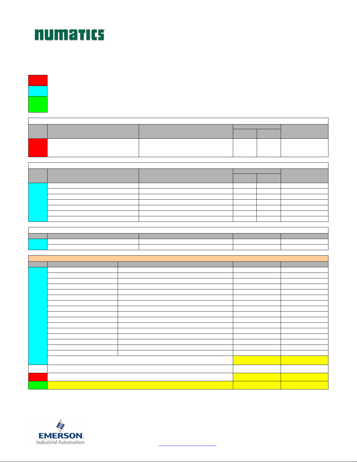
G3SeriesEtherNet/IPTechnicalManual
Manifold and I/O Data Sizing Worksheet
Step
: Choose appropriate value and place the corresponding Rx and Tx values in the boxes labeled, “Valve Byte Requirements” at the bottom
1
of the page
: Choose up to sixteen modules to be included on the discrete I/O side of the manifold and place sum of the corresponding input bytes and
2
output bytes in the boxes labeled, “Sub-Bus Byte Requirements” at the bottom of the page.
: Total the input bytes and output bytes values from the boxes labeled “Sub-Bus Byte Requirements” and “Valve Byte Requirements” in the
boxes labeled “Total Input and Output Bytes for Manifold. This is the total input and output byte values required for the configured
3
Valve Side
Step Valve Side
manifold.
Input Bytes (Rx)
Status
Enabled
Status
Disabled
Output Bytes (Tx)
1
Digital Modules
Step Module No. Description
2
Analog Modules
Step Module No. Description Input Bytes (Rx) Output Bytes (Tx)
2
Total Input/Output Size Calculation
Step Module Position Model Number Input Bytes (Rx) Output Bytes (Tx)
2
1
3
Up to 32 Solenoid Coils 4 0 4
Input Bytes (Rx)
Status
240-203/204 16 Inputs - Terminal Strip 3 2 0
240-205/209 16 Inputs - 8 x 12mm 3 2 0
240-206/210 8 Inputs - 8 x 12mm 2 1 0
240-207 16 Outputs - 8 x 12mm 2 0 2
240-208 8 Outputs - 8 x 12mm 1 0 1
240-211 8 Inputs / 8 Outputs - 8 x 12mm 3 1 1
240-241 Sub – Bus Valve Output 4 0 4
240-212/214 4 Inputs 8 0
240-213/215 2 Inputs/ 2 Outputs 4 4
1st
2nd
3rd
4th
5th
6th
7th
8th
9th
10th
11th
12th
13th
14th
15th
16th
Sub-Bus Byte Requirements:
Optional Diagnostic Word: 2 0
Valve Byte Requirements:
Total Input and Output Bytes for Manifold
Enabled
Status
Disabled
Output Bytes (Tx)
TDG3EPTM1-1EN 05/09
Subject to change without notice
Page 74
www.numatics.com/g3
Page 76
G3SeriesEtherNet/IPTechnicalManual
Bit Mapping Rules
The bit mapping for a G3 manifold varies with the physical configuration of the manifold. The following is a
breakdown of the bit mapping rules associated with the Numatics valve manifold.
Valve Side
1) Solenoid coil outputs are connected to the valve coils using the Z-Boards
2) The valve solenoid coil output portion of the total output size is fixed at 4 bytes.
3) Each solenoid coil output has an associated status input bit (refer to the section labeled, “Output Short
Circuit Protection”, on page 20 for functional details). The solenoid coil status input size is fixed at 4
bytes.
4) Solenoid coil output addressing begins at the 1
then, if applicable, the “12” coil, and continues in ascending order away from the communication node.
5) Each manifold station allocates 1 or 2 output bits. This is dependent on the Z-Board
A single Z-Board
6) Z-Boards
group No.1 and output group No. 2 bits do not overlap (i.e. combinations of Z-Boards
the physical configuration of the manifold could exceed the output capacity.
NOTE!
Discrete I/O Side
Outputs
1) The Sub-Bus output byte size portion is self-configuring in byte increments, after an output module is
installed on the Sub-Bus and power is applied.
2) Outputs are mapped consecutively by module. The output bits from the 1
directly after the bits from the valve coils. The output bits from the second module will be mapped
directly after the output bits from the 1
Inputs
1) The Sub-Bus input byte size portion is self-configuring in byte increments, after an input module is
plugged into back plane and power is applied.
2) Inputs are mapped consecutively by module. The input bits from the 1
after the status bits from the valve side. The input bits from the second module will be mapped directly
after the input bits from the 1
3) All of the modules have associated internal status bits, which will affect the total value of input bytes..
4) When a module has discrete and status inputs, the status bits are mapped after the discrete input bits.
st
manifold station nearest the node using “14” coil 1st and
™
allocates 1 output bit. A double Z-Board™ allocates 2 output bits.
™
can be used in any arrangement (all singles, all doubles, or any combination) as long as output
Single solenoid valves can be used with double
one of the two available outputs will remain unused.
st
module and so on.
Z-Boards
st
module and so on.
™
.
™
type installed.
™
could exist where
TM
. However,
st
module will be mapped
st
module will be mapped directly
TDG3EPTM1-1EN 05/09
Subject to change without notice
Page 75
www.numatics.com/g3
Page 77
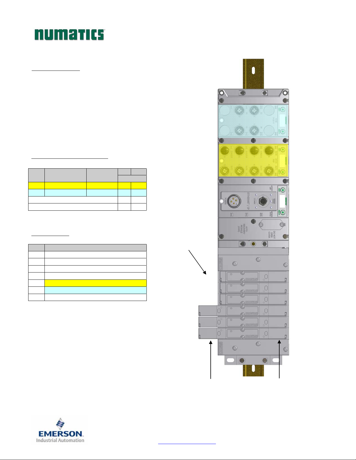
68
1
3
579
11
G3SeriesEtherNet/IPTechnicalManual
I/O Mapping Examples
Assumed Settings
Example No. 1
- Double Z-Boards
- I/O Modules and mapping schemes are identified
by their corresponding color.
- I/O Status bits are enabled
- Diagnostic Word is enabled
Manifold I/O Configuration
Pos
Module Type Part No.
No.
1 16IPNP 240‐205 3 0
2 4AIAnalog240‐212 10 0
TM
used with all valves
In Out
Bytes
DiagnosticWord2 0
LocalValveSize4 4
Total:194
How to Order
Qty Part Number
1 AK3EF00003NDRM
3 051BA4Z2MN00061
3 051BB4Z2MN00061
1 G3EP102R0G32
1 240‐205
1 240‐212
ASSEMBLED
ValveCoil
Number
Whenthe12End
Solenoidis
energized,the2port
ispressurized
0
2
4
10
Whenthe14End
Solenoidis
energized,the4port
ispressurized
TDG3EPTM1-1EN 05/09
Subject to change without notice
Page 76
www.numatics.com/g3
Page 78

G3SeriesEtherNet/IPTechnicalManual
Example No. 1 Table
Output Table
BYTE Bit 7 Bit 6 Bit 5 Bit 4 Bit 3 Bit 2 Bit 1 Bit 0
0
1
2
3
Valve Coil
No. 7
Allocated and
Reserved
Allocated and
Reserved
Allocated and
Reserved
BYTE Bit 7 Bit 6 Bit 5 Bit 4 Bit 3 Bit 2 Bit 1 Bit 0
0
(Optional)
1
(Optional)
2
(Optional)
3
(Optional)
4
(Optional)
5
(Optional)
6
7
8
(Optional)
9
10
11
12
13
14
15
16
17
(Optional)
18
(Optional)
Comm.
Module
Diagnostic Bit
Sub-bus
Diagnostic Bit
Coil No. 7
Status
Allocated and
Reserved
Allocated and
Reserved
Allocated and
Reserved
Discrete Input
No. 7
Discrete Input
No. 15
Power Status
for Conn. H
Analog
Input No. 1
Analog Input
No. 1 (MSB)
Analog
Input No. 2
Analog Input
No. 2 (MSB)
Analog
Input No. 3
Analog Input
No. 3 (MSB)
Analog
Input No. 4
Analog Input
No.4 (MSB)
Allocated and
Reserved
High Alarm
for Conn. D
NOTE!
Valve Coil
No. 6
Allocated and
Reserved
Allocated and
Reserved
Allocated and
Reserved
Valve Coil
No. 5
Allocated and
Reserved
Allocated and
Reserved
Allocated and
Reserved
Valve Coil
No. 4
Allocated and
Reserved
Allocated and
Reserved
Allocated and
Reserved
Valve Coil
No. 3
Valve Coil
No. 11
Allocated and
Reserved
Allocated and
Reserved
Valve Coil
No. 2
Valve Coil
No. 10
Allocated and
Reserved
Allocated and
Reserved
Valve Coil
No. 1
Valve Coil
No. 9
Allocated and
Reserved
Allocated and
Reserved
Input Table
Comm.
Module
Diagnostic Bit
Sub-bus
Diagnostic Bit
Coil No. 6
Status
Allocated and
Reserved
Allocated and
Reserved
Allocated and
Reserved
Discrete Input
No. 6
Discrete Input
No. 14
Power Status
for Conn. G
Analog
Input No. 1
Analog
Input No. 1
Analog
Input No. 2
Analog
Input No. 2
Analog
Input No. 3
Analog
Input No. 3
Analog
Input No. 4
Analog
Input No. 4
Allocated and
Reserved
Low Alarm for
Conn. D
Comm.
Module
Diagnostic Bit
Sub-bus
Diagnostic Bit
Coil No. 5
Status
Allocated and
Reserved
Allocated and
Reserved
Allocated and
Reserved
Discrete Input
No. 5
Discrete Input
No. 13
Power Status
for Conn. F
Analog
Input No. 1
Analog
Input No. 1
Analog
Input No. 2
Analog
Input No. 2
Analog
Input No. 3
Analog
Input No. 3
Analog
Input No. 4
Analog
Input No. 4
Allocated and
Reserved
High Alarm
for Conn. C
Comm.
Module
Diagnostic Bit
Sub-bus
Diagnostic Bit
Coil No. 4
Status
Allocated and
Reserved
Allocated and
Reserved
Allocated and
Reserved
Discrete Input
No. 4
Discrete Input
No. 12
Power Status
for Conn. E
Analog
Input No. 1
Analog
Input No. 1
Analog
Input No. 2
Analog
Input No. 2
Analog
Input No. 3
Analog
Input No. 3
Analog
Input No. 4
Analog
Input No. 4
Allocated and
Reserved
Low Alarm for
Conn. C
Comm.
Module
Diagnostic Bit
Sub-bus
Diagnostic Bit
Coil No. 3
Status
Coil No. 11
Status
Allocated and
Reserved
Allocated and
Reserved
Discrete Input
No. 3
Discrete Input
No. 11
Power Status
for Conn. D
Analog
Input No. 1
Analog
Input No. 1
Analog
Input No. 2
Analog
Input No. 2
Analog
Input No. 3
Analog
Input No. 3
Analog
Input No. 4
Analog
Input No. 4
Power Status
for Conn. D
High Alarm for
Conn. B
Comm.
Module
Diagnostic Bit
Sub-bus
Diagnostic Bit
Coil No. 2
Status
Coil No. 10
Status
Allocated and
Reserved
Allocated and
Reserved
Discrete Input
No. 2
Discrete Input
No. 10
Power Status
for Conn. C
Analog
Input No. 1
Analog
Input No. 1
Analog
Input No. 2
Analog
Input No. 2
Analog
Input No. 3
Analog
Input No. 3
Analog
Input No. 4
Analog
Input No. 4
Power Status
for Conn. C
Low Alarm for
Conn. B
Comm.
Module
Diagnostic Bit
Sub-bus
Diagnostic Bit
Coil No. 1
Status
Coil No. 9
Status
Allocated and
Reserved
Allocated and
Reserved
Discrete Input
No. 1
Discrete Input
No. 9
Power Status
for Conn. B
Analog
Input No. 1
Analog
Input No. 1
Analog
Input No. 2
Analog
Input No. 2
Analog
Input No. 3
Analog
Input No. 3
Analog
Input No. 4
Analog
Input No. 4
Power Status
for Conn. B
High Alarm
for Conn. A
The Comm. Module Diagnostic Bits, Sub-Bus Diagnostic Bits, Coil Status Bits
and Power Status Bits are optional. The factory default condition is Diagnostic
bits enabled. These bits may be disabled to optimize the logical size of the
manifold.
Valve Coil
No. 0
Valve Coil
No. 8
Allocated and
Reserved
Allocated and
Reserved
Comm.
Module
Diagnostic Bit
Sub-bus
Diagnostic Bit
Coil No. 0
Status
Coil No. 8
Status
Allocated and
Reserved
Allocated and
Reserved
Discrete Input
No. 0
Discrete Input
No. 8
Power Status
for Conn. A
Analog Input
No. 1 (LSB)
Analog
Input No. 1
Analog Input
No. 2 (LSB)
Analog
Input No. 2
Analog Input
No. 3 (LSB)
Analog
Input No. 3
Analog Input
No. 4 (LSB)
Analog
Input No. 4
Power Status
for Conn. A
Low Alarm for
Conn. A
TDG3EPTM1-1EN 05/09
Subject to change without notice
Page 77
www.numatics.com/g3
Page 79
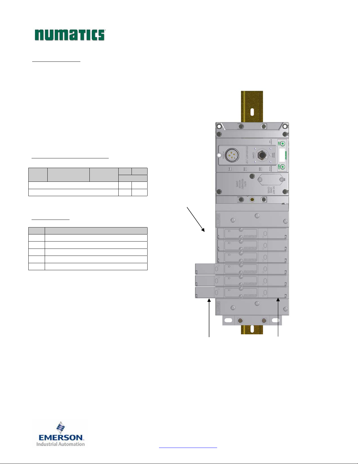
2468
13579
11
G3SeriesEtherNet/IPTechnicalManual
Assumed Settings
Example No. 2
- Double Z-Boards
- I/O Modules and mapping schemes are
identified by their corresponding color.
- I/O Status bits are enabled
- Diagnostic Word is enabled
Manifold I/O Configuration
Pos.
No.
How to Order
Qty Part Number
Module Type Part No.
DiagnosticWord2 0
LocalValveSize:4 4
1 AK3EF00003NDRM
3 051BA4Z2MN00061
3 051BB4Z2MN00061
1 G3EP100R0G32
ASSEMBLED
TM
used with all valves
In Out
Bytes
Total:6 4
ValveCoil
Number
0
10
Whenthe12End
Solenoidis
energized,the2port
ispressurized
TDG3EPTM1-1EN 05/09
Subject to change without notice
Page 78
www.numatics.com/g3
Whenthe14End
Solenoidis
energized,the4port
ispressurized
Page 80
d
G3SeriesEtherNet/IPTechnicalManual
Example No. 2 Table
Output Table
BYTE Bit 7 Bit 6 Bit 5 Bit 4 Bit 3 Bit 2 Bit 1 Bit 0
0
1
2
3
Valve Coil
No. 7
Allocated and
Reserved
Allocated and
Reserved
Allocated and
Reserved
BYTE Bit 7 Bit 6 Bit 5 Bit 4 Bit 3 Bit 2 Bit 1 Bit 0
0
(Optional)
1
(Optional)
2
(Optional)
3
(Optional)
4
(Optional)
5
(Optional)
Comm.
Module
Diagnostic Bit
Sub-bus
Diagnostic Bit
Coil No. 7
Status
Coil No. 15
Status
Coil No. 23
Status
Coil No. 31
Status
Valve Coil
No. 6
Allocated and
Reserved
Allocated and
Reserved
Allocated and
Reserved
Comm.
Module
Diagnostic Bit
Sub-bus
Diagnostic Bit
Coil No. 6
Status
Coil No. 14
Status
Coil No. 22
Status
Coil No. 30
Status
Valve Coil
No. 5
Allocated and
Reserved
Allocated and
Reserved
Allocated and
Reserved
Comm.
Module
Diagnostic Bit
Sub-bus
Diagnostic Bit
Coil No. 5
Status
Coil No. 13
Status
Coil No. 21
Status
Coil No. 29
Status
Valve Coil
No. 4
Allocated and
Reserved
Allocated and
Reserved
Allocated and
Reserved
Input Table
Comm.
Module
Diagnostic Bit
Sub-bus
Diagnostic Bit
Coil No. 4
Status
Coil No. 12
Status
Coil No. 20
Status
Coil No. 28
Status
Valve Coil
No. 3
Valve Coil
No. 11
Allocated and
Reserved
Allocated and
Reserved
Comm.
Module
Diagnostic Bit
Sub-bus
Diagnostic Bit
Coil No. 3
Status
Coil No. 11
Status
Coil No. 19
Status
Coil No. 27
Status
Valve Coil
No. 2
Valve Coil
No. 10
Allocated and
Reserved
Allocated and
Reserved
Comm.
Module
Diagnostic Bit
Sub-bus
Diagnostic Bit
Coil No. 2
Status
Coil No. 10
Status
Coil No. 18
Status
Coil No. 26
Status
Valve Coil
No. 1
Valve Coil
No. 9
Allocated and
Reserved
Allocated and
Reserved
Comm.
Module
Diagnostic Bit
Sub-bus
Diagnostic Bit
Coil No. 1
Status
Coil No. 9
Status
Coil No. 17
Status
Coil No. 25
Status
Valve Coil
No. 0
Valve Coil
No. 8
Allocated and
Reserved
Allocated and
Reserved
Comm.
Module
Diagnostic Bit
Sub-bus
Diagnostic Bit
Coil No. 0
Status
Coil No. 8
Status
Coil No. 16
Status
Coil No. 24
Status
NOTE!
The Comm. Module Diagnostic Bits, Sub-Bus Diagnostic Bits, Coil Status Bits
and Power Status Bits are optional. The factory default condition is Diagnostic
bits are enabled. These bits may be disabled to optimize the logical size of the
manifol
TDG3EPTM1-1EN 05/09
Subject to change without notice
Page 79
www.numatics.com/g3
Page 81
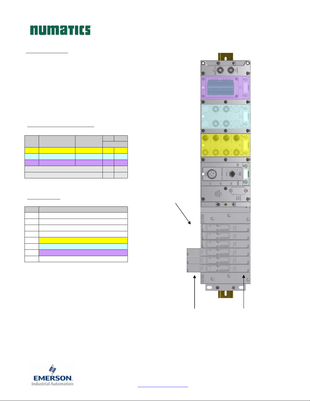
24
1357
9
11
G3SeriesEtherNet/IPTechnicalManual
Assumed Settings
Example No. 3
- Double Z-Boards
- I/O Modules and mapping schemes are identified
by their corresponding color.
- I/O Status bits are enabled
- Diagnostic Word is enabled
Manifold I/O Configuration
Pos
Module Type Part No.
No.
1 16IPNP 240‐205 3 0
2 4AIAnalog240‐212 10 0
3 16IPNP 240‐203 3 0
How to Order
Qty Part Number
1 AK3EF00003NDRM
3 051BA4Z2MN00061
3 051BB4Z2MN00061
1 G3EP103D0G32
1 240‐205
1 240‐212
1 240‐203
ASSEMBLED
TM
used with all valves
In Out
Bytes
DiagnosticWord2 0
LocalValves:4 4
Total:22 4
ValveCoil
Number
0
6
8
10
Whenthe12End
Solenoidis
energized,the2port
ispressurized
TDG3EPTM1-1EN 05/09
Subject to change without notice
Page 80
www.numatics.com/g3
Whenthe14End
Solenoidis
energized,the4port
ispressurized
Page 82

G3SeriesEtherNet/IPTechnicalManual
Example No. 3 Table
Output Table
BYTE Bit 7 Bit 6 Bit 5 Bit 4 Bit 3 Bit 2 Bit 1 Bit 0
0
1
2
3
BYTE Bit 7 Bit 6 Bit 5 Bit 4 Bit 3 Bit 2 Bit 1 Bit 0
0
(Optional)
1
(Optional)
2
(Optional)
3
(Optional)
4
(Optional)
5
(Optional)
6
7
8
(Optional)
9
10
11
12
13
14
15
16
17
(Optional)
18
(Optional)
19
20
21
(Optional)
Valve Coil
No. 7
Allocated and
Reserved
Allocated and
Reserved
Allocated and
Reserved
Comm.
Module
Diagnostic Bit
Sub-bus
Diagnostic Bit
Coil No. 7
Status
Coil No. 15
Status
Coil No. 23
Status
Coil No. 31
Status
Discrete Input
No. 7
Discrete Input
No. 15
Power Status
for Conn. H
Analog
Input No. 1
Analog Input
No. 1 (MSB)
Analog
Input No. 2
Analog Input
No. 2 (MSB)
Analog
Input No. 3
Analog Input
No. 3 (MSB)
Analog
Input No. 4
Analog Input
No.4 (MSB)
Allocated and
Reserved
High Alarm
for Conn. D
Discrete Input
No. 7
Discrete Input
No. 15
Power Status
for Conn. H
Valve Coil
No. 6
Allocated and
Reserved
Allocated and
Reserved
Allocated and
Reserved
Comm.
Module
Diagnostic Bit
Sub-bus
Diagnostic Bit
Coil No. 6
Status
Coil No. 14
Status
Coil No. 22
Status
Coil No. 30
Status
Discrete Input
No. 6
Discrete Input
No. 14
Power Status
for Conn. G
Analog
Input No. 1
Analog
Input No. 1
Analog
Input No. 2
Analog
Input No. 2
Analog
Input No. 3
Analog
Input No. 3
Analog
Input No. 4
Analog
Input No. 4
Allocated and
Reserved
Low Alarm for
Conn. D
Discrete Input
No. 6
Discrete Input
No. 14
Power Status
for Conn. G
Valve Coil
No. 5
Allocated and
Reserved
Allocated and
Reserved
Allocated and
Reserved
Comm.
Module
Diagnostic Bit
Sub-bus
Diagnostic Bit
Coil No. 5
Status
Coil No. 13
Status
Coil No. 21
Status
Coil No. 29
Status
Discrete Input
No. 5
Discrete Input
No. 13
Power Status
for Conn. F
Analog
Input No. 1
Analog
Input No. 1
Analog
Input No. 2
Analog
Input No. 2
Analog
Input No. 3
Analog
Input No. 3
Analog
Input No. 4
Analog
Input No. 4
Allocated and
Reserved
High Alarm
for Conn. C
Discrete Input
No. 5
Discrete Input
No. 13
Power Status
for Conn. F
Valve Coil
No. 4
Allocated and
Reserved
Allocated and
Reserved
Allocated and
Reserved
Input Table
Comm.
Module
Diagnostic Bit
Sub-bus
Diagnostic Bit
Coil No. 4
Status
Coil No. 12
Status
Coil No. 20
Status
Coil No. 28
Status
Discrete Input
No. 4
Discrete Input
No. 12
Power Status
for Conn. E
Analog
Input No. 1
Analog
Input No. 1
Analog
Input No. 2
Analog
Input No. 2
Analog
Input No. 3
Analog
Input No. 3
Analog
Input No. 4
Analog
Input No. 4
Allocated and
Reserved
Low Alarm for
Conn. C
Discrete Input
No. 4
Discrete Input
No. 12
Power Status
for Conn. E
Valve Coil
No. 3
Valve Coil
No. 11
Allocated and
Reserved
Allocated and
Reserved
Comm.
Module
Diagnostic Bit
Sub-bus
Diagnostic Bit
Coil No. 3
Status
Coil No. 11
Status
Coil No. 19
Status
Coil No. 27
Status
Discrete Input
No. 3
Discrete Input
No. 11
Power Status
for Conn. D
Analog
Input No. 1
Analog
Input No. 1
Analog
Input No. 2
Analog
Input No. 2
Analog
Input No. 3
Analog
Input No. 3
Analog
Input No. 4
Analog
Input No. 4
Power Status
for Conn. D
High Alarm for
Conn. B
Discrete Input
No. 3
Discrete Input
No. 11
Power Status
for Conn. D
Valve Coil
No. 2
Valve Coil
No. 10
Allocated and
Reserved
Allocated and
Reserved
Comm.
Module
Diagnostic Bit
Sub-bus
Diagnostic Bit
Coil No. 2
Status
Coil No. 10
Status
Coil No. 18
Status
Coil No. 26
Status
Discrete Input
No. 2
Discrete Input
No. 10
Power Status
for Conn. C
Analog
Input No. 1
Analog
Input No. 1
Analog
Input No. 2
Analog
Input No. 2
Analog
Input No. 3
Analog
Input No. 3
Analog
Input No. 4
Analog
Input No. 4
Power Status
for Conn. C
Low Alarm for
Conn. B
Discrete Input
No. 2
Discrete Input
No. 10
Power Status
for Conn. C
Valve Coil
No. 1
Valve Coil
No. 9
Allocated and
Reserved
Allocated and
Reserved
Comm.
Module
Diagnostic Bit
Sub-bus
Diagnostic Bit
Coil No. 1
Status
Coil No. 9
Status
Coil No. 17
Status
Coil No. 25
Status
Discrete Input
No. 1
Discrete Input
No. 9
Power Status
for Conn. B
Analog
Input No. 1
Analog
Input No. 1
Analog
Input No. 2
Analog
Input No. 2
Analog
Input No. 3
Analog
Input No. 3
Analog
Input No. 4
Analog
Input No. 4
Power Status
for Conn. B
High Alarm
for Conn. A
Discrete Input
No. 1
Discrete Input
No. 9
Power Status
for Conn. B
Valve Coil
No. 0
Valve Coil
No. 8
Allocated and
Reserved
Allocated and
Reserved
Comm.
Module
Diagnostic Bit
Sub-bus
Diagnostic Bit
Coil No. 0
Status
Coil No. 8
Status
Coil No. 16
Status
Coil No. 24
Status
Discrete Input
No. 0
Discrete Input
No. 8
Power Status
for Conn. A
Analog Input
No. 1 (LSB)
Analog
Input No. 1
Analog Input
No. 2 (LSB)
Analog
Input No. 2
Analog Input
No. 3 (LSB)
Analog
Input No. 3
Analog Input
No. 4 (LSB)
Analog
Input No. 4
Power Status
for Conn. A
Low Alarm for
Conn. A
Discrete Input
No. 0
Discrete Input
No. 8
Power Status
for Conn. A
TDG3EPTM1-1EN 05/09
Subject to change without notice
Page 81
www.numatics.com/g3
Page 83
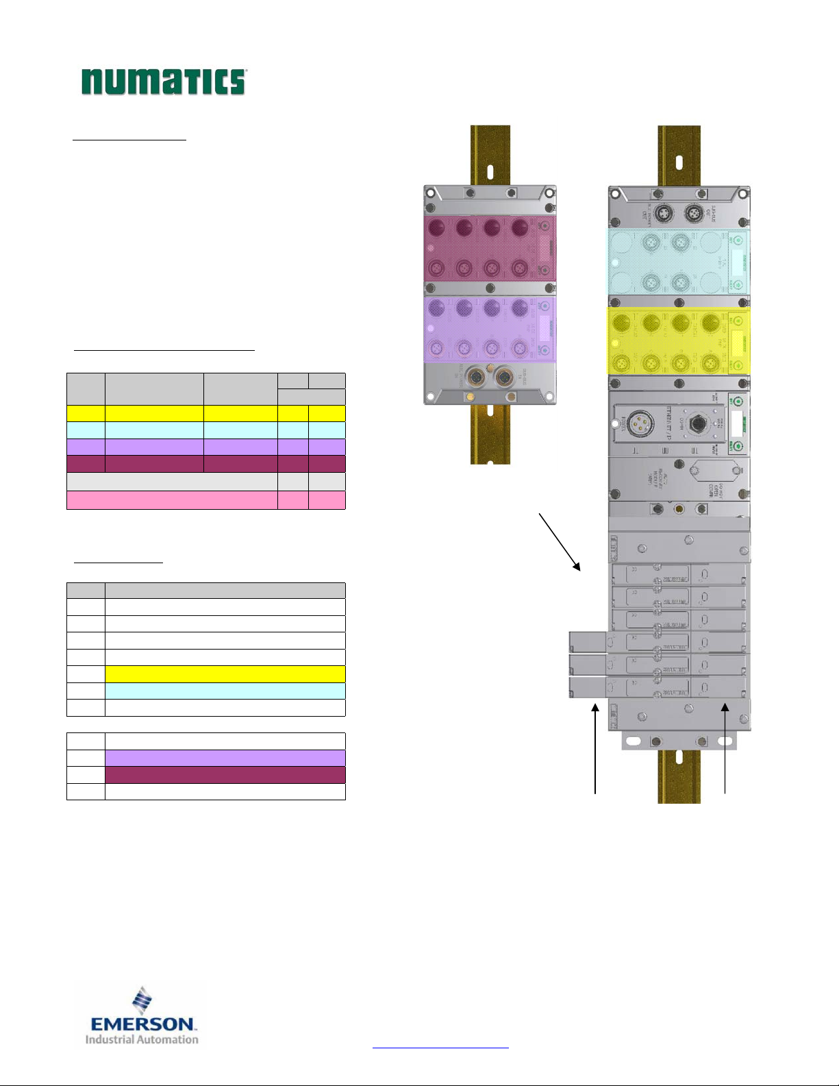
0
2
4
68
10
3579
1
Assumed Settings
Example No. 4
- Double Z-Boards
- I/O Modules and mapping schemes are identified
by their corresponding color.
- I/O Status bits are enabled
- Diagnostic Word is enabled
TM
used with all valves
G3SeriesEtherNet/IPTechnicalManual
Manifold I/O Configuration
Pos
Module Type Part No.
No.
1 16IPNP 240‐205 3 0
2 4IAnalog 240‐212 10 0
3 16IPNP 240‐205 3 0
4 16IPNP 240‐205 3 0
DiagnosticWord2 0
LocalValves:4 4
Total:18 4
How to Order
In Out
Bytes
Qty Part Number
1 AK3EF00003NDRM
3 051BA4Z2MN00061
3 051BB4Z2MN00061
1 G3EP102R0G32
1 240‐205
1 240‐212
ASSEMBLED
1 G3DS302D0DRM
1 240‐205
1 240‐205
ASSEMBLED
ValveCoil
Number
1
1
Whenthe12End
Solenoidis
energized,the2port
ispressurized
Whenthe14End
Solenoidis
energized,the4port
ispressurized
TDG3EPTM1-1EN 05/09
Subject to change without notice
Page 82
www.numatics.com/g3
Page 84

G3SeriesEtherNet/IPTechnicalManual
Example No. 4 Table
Output Table
BYTE Bit 7 Bit 6 Bit 5 Bit 4 Bit 3 Bit 2 Bit 1 Bit 0
0
1
2
3
BYTE Bit 7 Bit 6 Bit 5 Bit 4 Bit 3 Bit 2 Bit 1 Bit 0
0
(Optional)
1
(Optional)
2
(Optional)
3
(Optional)
4
(Optional)
5
(Optional)
6
7
8
(Optional)
9
10
11
12
13
14
15
16
17
(Optional)
18
(Optional)
19
20
21
(Optional)
22
23
24
(Optional)
Valve Coil
No. 7
Allocated and
Reserved
Allocated and
Reserved
Allocated and
Reserved
Comm.
Module
Diagnostic Bit
Sub-bus
Diagnostic Bit
Coil No. 7
Status
Coil No. 15
Status
Coil No. 23
Status
Coil No. 31
Status
Discrete Input
No. 7
Discrete Input
No. 15
Power Status
for Conn. H
Analog
Input No. 1
Analog Input
No. 1 (MSB)
Analog
Input No. 2
Analog Input
No. 2 (MSB)
Analog
Input No. 3
Analog Input
No. 3 (MSB)
Analog
Input No. 4
Analog Input
No.4 (MSB)
Allocated and
Reserved
High Alarm
for Conn. D
Discrete Input
No. 7
Discrete Input
No. 15
Power Status
for Conn. H
Discrete Input
No. 7
Discrete Input
No. 15
Power Status
for Conn. H
Valve Coil
No. 6
Allocated and
Reserved
Allocated and
Reserved
Allocated and
Reserved
Comm.
Module
Diagnostic Bit
Sub-bus
Diagnostic Bit
Coil No. 6
Status
Coil No. 14
Status
Coil No. 22
Status
Coil No. 30
Status
Discrete Input
No. 6
Discrete Input
No. 14
Power Status
for Conn. G
Analog
Input No. 1
Analog
Input No. 1
Analog
Input No. 2
Analog
Input No. 2
Analog
Input No. 3
Analog
Input No. 3
Analog
Input No. 4
Analog
Input No. 4
Allocated and
Reserved
Low Alarm for
Conn. D
Discrete Input
No. 6
Discrete Input
No. 14
Power Status
for Conn. G
Discrete Input
No. 6
Discrete Input
No. 14
Power Status
for Conn. G
Valve Coil
No. 5
Allocated and
Reserved
Allocated and
Reserved
Allocated and
Reserved
Comm.
Module
Diagnostic Bit
Sub-bus
Diagnostic Bit
Coil No. 5
Status
Coil No. 13
Status
Coil No. 21
Status
Coil No. 29
Status
Discrete Input
No. 5
Discrete Input
No. 13
Power Status
for Conn. F
Analog
Input No. 1
Analog
Input No. 1
Analog
Input No. 2
Analog
Input No. 2
Analog
Input No. 3
Analog
Input No. 3
Analog
Input No. 4
Analog
Input No. 4
Allocated and
Reserved
High Alarm
for Conn. C
Discrete Input
No. 5
Discrete Input
No. 13
Power Status
for Conn. F
Discrete Input
No. 5
Discrete Input
No. 13
Power Status
for Conn. F
Valve Coil
No. 4
Allocated and
Reserved
Allocated and
Reserved
Allocated and
Reserved
Input Table
Comm.
Module
Diagnostic Bit
Sub-bus
Diagnostic Bit
Coil No. 4
Status
Coil No. 12
Status
Coil No. 20
Status
Coil No. 28
Status
Discrete Input
No. 4
Discrete Input
No. 12
Power Status
for Conn. E
Analog
Input No. 1
Analog
Input No. 1
Analog
Input No. 2
Analog
Input No. 2
Analog
Input No. 3
Analog
Input No. 3
Analog
Input No. 4
Analog
Input No. 4
Allocated and
Reserved
Low Alarm for
Conn. C
Discrete Input
No. 4
Discrete Input
No. 12
Power Status
for Conn. E
Discrete Input
No. 4
Discrete Input
No. 12
Power Status
for Conn. E
Valve Coil
No. 3
Valve Coil
No. 11
Allocated and
Reserved
Allocated and
Reserved
Comm.
Module
Diagnostic Bit
Sub-bus
Diagnostic Bit
Coil No. 3
Status
Coil No. 11
Status
Coil No. 19
Status
Coil No. 27
Status
Discrete Input
No. 3
Discrete Input
No. 11
Power Status
for Conn. D
Analog
Input No. 1
Analog
Input No. 1
Analog
Input No. 2
Analog
Input No. 2
Analog
Input No. 3
Analog
Input No. 3
Analog
Input No. 4
Analog
Input No. 4
Power Status
for Conn. D
High Alarm for
Conn. B
Discrete Input
No. 3
Discrete Input
No. 11
Power Status
for Conn. D
Discrete Input
No. 3
Discrete Input
No. 11
Power Status
for Conn. D
Valve Coil
No. 2
Valve Coil
No. 10
Allocated and
Reserved
Allocated and
Reserved
Comm.
Module
Diagnostic Bit
Sub-bus
Diagnostic Bit
Coil No. 2
Status
Coil No. 10
Status
Coil No. 18
Status
Coil No. 26
Status
Discrete Input
No. 2
Discrete Input
No. 10
Power Status
for Conn. C
Analog
Input No. 1
Analog
Input No. 1
Analog
Input No. 2
Analog
Input No. 2
Analog
Input No. 3
Analog
Input No. 3
Analog
Input No. 4
Analog
Input No. 4
Power Status
for Conn. C
Low Alarm for
Conn. B
Discrete Input
No. 2
Discrete Input
No. 10
Power Status
for Conn. C
Discrete Input
No. 2
Discrete Input
No. 10
Power Status
for Conn. C
Valve Coil
No. 1
Valve Coil
No. 9
Allocated and
Reserved
Allocated and
Reserved
Comm.
Module
Diagnostic Bit
Sub-bus
Diagnostic Bit
Coil No. 1
Status
Coil No. 9
Status
Coil No. 17
Status
Coil No. 25
Status
Discrete Input
No. 1
Discrete Input
No. 9
Power Status
for Conn. B
Analog
Input No. 1
Analog
Input No. 1
Analog
Input No. 2
Analog
Input No. 2
Analog
Input No. 3
Analog
Input No. 3
Analog
Input No. 4
Analog
Input No. 4
Power Status
for Conn. B
High Alarm
for Conn. A
Discrete Input
No. 1
Discrete Input
No. 9
Power Status
for Conn. B
Discrete Input
No. 1
Discrete Input
No. 9
Power Status
for Conn. B
Valve Coil
No. 0
Valve Coil
No. 8
Allocated and
Reserved
Allocated and
Reserved
Comm.
Module
Diagnostic Bit
Sub-bus
Diagnostic Bit
Coil No. 0
Status
Coil No. 8
Status
Coil No. 16
Status
Coil No. 24
Status
Discrete Input
No. 0
Discrete Input
No. 8
Power Status
for Conn. A
Analog Input
No. 1 (LSB)
Analog
Input No. 1
Analog Input
No. 2 (LSB)
Analog
Input No. 2
Analog Input
No. 3 (LSB)
Analog
Input No. 3
Analog Input
No. 4 (LSB)
Analog
Input No. 4
Power Status
for Conn. A
Low Alarm for
Conn. A
Discrete Input
No. 0
Discrete Input
No. 8
Power Status
for Conn. A
Discrete Input
No. 0
Discrete Input
No. 8
Power Status
for Conn. A
TDG3EPTM1-1EN 05/09
Subject to change without notice
Page 83
www.numatics.com/g3
Page 85
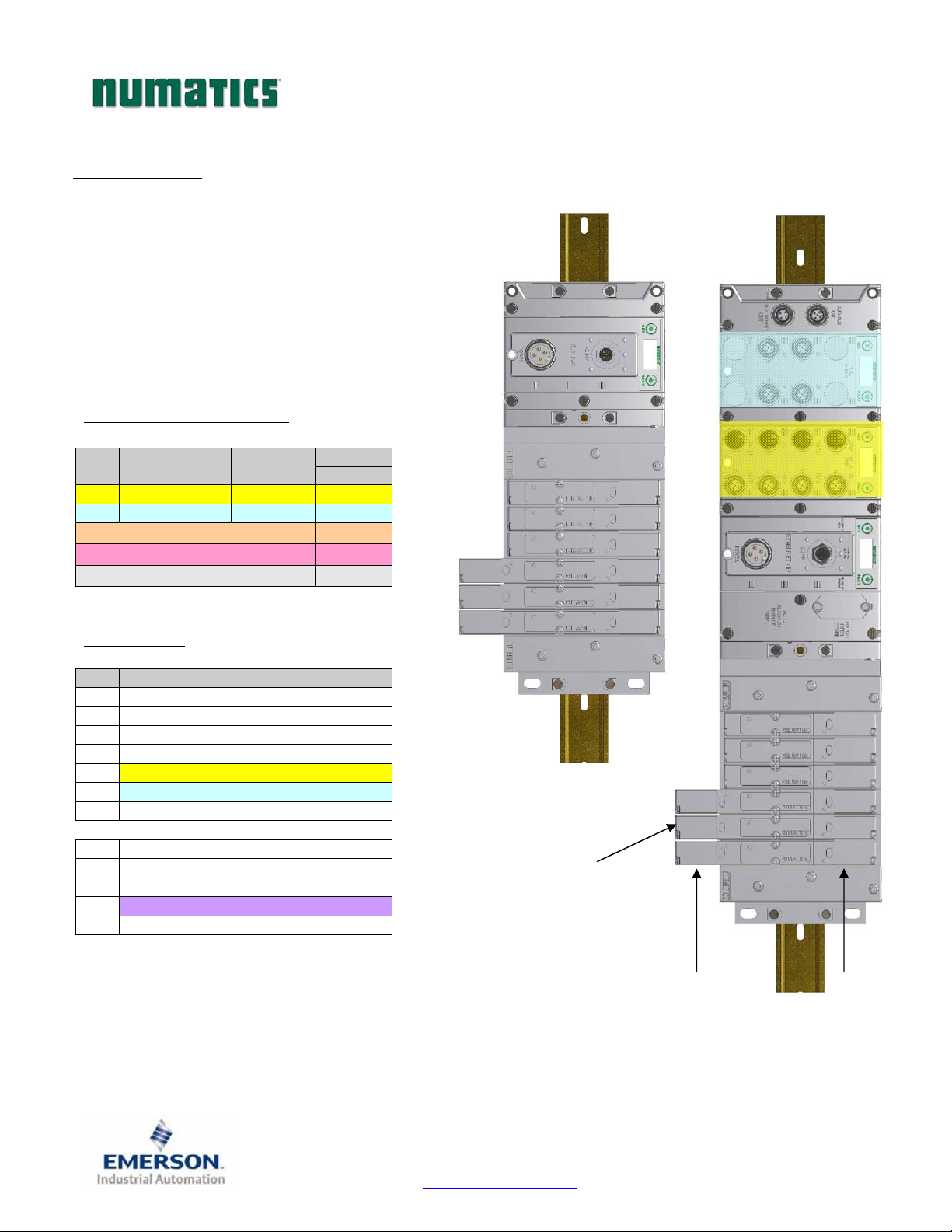
02
46
8
10
3
02468
10
13
5
79
11
G3SeriesEtherNet/IPTechnicalManual
Assumed Settings
Example No. 5
- Double Z-Boards
- I/O Modules and mapping schemes are identified
by their corresponding color.
- I/O Status bits are enabled
- Diagnostic Word is enabled
Manifold I/O Configuration
Pos
Module Type Part No.
No.
1 16IPNP 240‐205 3 0
2 4IAnalog 240‐212 10 0
LocalValves(DeviceNet)4 4
LocalValves(Sub‐Bus)4 4
How to Order
Qty Part Number
1 AK3EF00003NDRM
3 051BA4Z2MN00061
3 051BB4Z2MN00061
1 G3DN102D0G32
1 240‐205
1 240‐212
ASSEMBLED
1 AK3EF00003NDRM
3 051BA4Z2MN00061
3 051BB4Z2MN00061
1 G3DS202R0DRM
ASSEMBLED
TM
used with all valves
In Out
Bytes
DiagnosticWord2 0
Total:23 8
1
5
7
9
11
ValveCoil
Number
Whenthe12End
Solenoidis
energized,the2port
ispressurized
TDG3EPTM1-1EN 05/09
Subject to change without notice
Page 84
www.numatics.com/g3
Whenthe14End
Solenoidis
energized,the4port
ispressurized
Page 86

G3SeriesEtherNet/IPTechnicalManual
Example No. 5 Table
Output Table
BYTE Bit 7 Bit 6 Bit 5 Bit 4 Bit 3 Bit 2 Bit 1 Bit 0
0
1
2
3
4
5
6
(Optional)
7
(Optional)
BYTE Bit 7 Bit 6 Bit 5 Bit 4 Bit 3 Bit 2 Bit 1 Bit 0
0
(Optional)
1
(Optional)
2
(Optional)
3
(Optional)
4
(Optional)
5
(Optional)
6
7
8
(Optional)
9
10
11
12
13
14
15
16
17
(Optional)
18
(Optional)
18
(Optional)
19
(Optional)
20
(Optional)
21
(Optional)
Valve Coil
No. 7
Allocated and
Reserved
Allocated and
Reserved
Allocated and
Reserved
Valve Coil
No. 7
Allocated and
Reserved
Allocated and
Reserved
Allocated and
Reserved
Comm. Module
Diagnostic Bit
Sub-bus
Diagnostic Bit
Coil No. 7
Status
Coil No. 15
Status
Coil No. 23
Status
Coil No. 31
Status
Discrete Input
No. 7
Discrete Input
No. 15
Power Status for
Conn. H
Analog
Input No. 1
Analog Input
No. 1 (MSB)
Analog
Input No. 2
Analog Input
No. 2 (MSB)
Analog
Input No. 3
Analog Input
No. 3 (MSB)
Analog
Input No. 4
Analog Input
No.4 (MSB)
Allocated and
Reserved
High Alarm for
Conn. D
Coil No. 7
Status
Coil No. 15
Status
Coil No. 23
Status
Coil No. 31
Status
Valve Coil
No. 6
Allocated and
Reserved
Allocated and
Reserved
Allocated and
Reserved
Valve Coil
No. 6
Allocated and
Reserved
Allocated and
Reserved
Allocated and
Reserved
Comm. Module
Diagnostic Bit
Sub-bus
Diagnostic Bit
Coil No. 6
Status
Coil No. 14
Status
Coil No. 22
Status
Coil No. 30
Status
Discrete Input
No. 6
Discrete Input
No. 14
Power Status for
Conn. G
Analog
Input No. 1
Analog
Input No. 1
Analog
Input No. 2
Analog
Input No. 2
Analog
Input No. 3
Analog
Input No. 3
Analog
Input No. 4
Analog
Input No. 4
Allocated and
Reserved
Low Alarm for
Conn. D
Coil No. 6
Status
Coil No. 14
Status
Coil No. 22
Status
Coil No. 30
Status
Valve Coil
No. 5
Allocated and
Reserved
Allocated and
Reserved
Allocated and
Reserved
Valve Coil
No. 5
Allocated and
Reserved
Allocated and
Reserved
Allocated and
Reserved
Comm. Module
Diagnostic Bit
Sub-bus
Diagnostic Bit
Coil No. 5
Status
Coil No. 13
Status
Coil No. 21
Status
Coil No. 29
Status
Discrete Input
No. 5
Discrete Input
No. 13
Power Status for
Conn. F
Analog
Input No. 1
Analog
Input No. 1
Analog
Input No. 2
Analog
Input No. 2
Analog
Input No. 3
Analog
Input No. 3
Analog
Input No. 4
Analog
Input No. 4
Allocated and
Reserved
High Alarm for
Conn. C
Coil No. 5
Status
Coil No. 13
Status
Coil No. 21
Status
Coil No. 29
Status
Valve Coil
No. 4
Allocated and
Reserved
Allocated and
Reserved
Allocated and
Reserved
Valve Coil
No. 4
Allocated and
Reserved
Allocated and
Reserved
Allocated and
Reserved
Input Table
Comm. Module
Diagnostic Bit
Sub-bus
Diagnostic Bit
Coil No. 4
Status
Coil No. 12
Status
Coil No. 20
Status
Coil No. 28
Status
Discrete Input
No. 4
Discrete Input
No. 12
Power Status for
Conn. E
Analog
Input No. 1
Analog
Input No. 1
Analog
Input No. 2
Analog
Input No. 2
Analog
Input No. 3
Analog
Input No. 3
Analog
Input No. 4
Analog
Input No. 4
Allocated and
Reserved
Low Alarm for
Conn. C
Coil No. 4
Status
Coil No. 12
Status
Coil No. 20
Status
Coil No. 28
Status
Valve Coil
No. 3
Valve Coil
No. 11
Allocated and
Reserved
Allocated and
Reserved
Valve Coil
No. 3
Valve Coil
No. 11
Allocated and
Reserved
Allocated and
Reserved
Comm. Module
Diagnostic Bit
Sub-bus
Diagnostic Bit
Coil No. 3
Status
Coil No. 11
Status
Coil No. 19
Status
Coil No. 27
Status
Discrete Input
No. 3
Discrete Input
No. 11
Power Status for
Conn. D
Analog
Input No. 1
Analog
Input No. 1
Analog
Input No. 2
Analog
Input No. 2
Analog
Input No. 3
Analog
Input No. 3
Analog
Input No. 4
Analog
Input No. 4
Power Status for
Conn. D
High Alarm for
Conn. B
Coil No. 3
Status
Coil No. 11
Status
Coil No. 19
Status
Coil No. 27
Status
Valve Coil
No. 2
Valve Coil
No. 10
Allocated and
Reserved
Allocated and
Reserved
Valve Coil
No. 2
Valve Coil
No. 10
Allocated and
Reserved
Allocated and
Reserved
Comm. Module
Diagnostic Bit
Sub-bus
Diagnostic Bit
Coil No. 2
Status
Coil No. 10
Status
Coil No. 18
Status
Coil No. 26
Status
Discrete Input
No. 2
Discrete Input
No. 10
Power Status for
Conn. C
Analog
Input No. 1
Analog
Input No. 1
Analog
Input No. 2
Analog
Input No. 2
Analog
Input No. 3
Analog
Input No. 3
Analog
Input No. 4
Analog
Input No. 4
Power Status for
Conn. C
Low Alarm for
Conn. B
Coil No. 2
Status
Coil No. 10
Status
Coil No. 18
Status
Coil No. 26
Status
Valve Coil
No. 1
Valve Coil
No. 9
Allocated and
Reserved
Allocated and
Reserved
Valve Coil
No. 1
Valve Coil
No. 9
Allocated and
Reserved
Allocated and
Reserved
Comm. Module
Diagnostic Bit
Sub-bus
Diagnostic Bit
Coil No. 1
Status
Coil No. 9
Status
Coil No. 17
Status
Coil No. 25
Status
Discrete Input
No. 1
Discrete Input
No. 9
Power Status for
Conn. B
Analog
Input No. 1
Analog
Input No. 1
Analog
Input No. 2
Analog
Input No. 2
Analog
Input No. 3
Analog
Input No. 3
Analog
Input No. 4
Analog
Input No. 4
Power Status for
Conn. B
High Alarm for
Conn. A
Coil No. 1
Status
Coil No. 9
Status
Coil No. 17
Status
Coil No. 25
Status
Valve Coil
No. 0
Valve Coil
No. 8
Allocated and
Reserved
Allocated and
Reserved
Valve Coil
No. 0
Valve Coil
No. 8
Allocated and
Reserved
Allocated and
Reserved
Comm. Module
Diagnostic Bit
Sub-bus
Diagnostic Bit
Coil No. 0
Status
Coil No. 8
Status
Coil No. 16
Status
Coil No. 24
Status
Discrete Input
No. 0
Discrete Input
No. 8
Power Status for
Conn. A
Analog Input
No. 1 (LSB)
Analog
Input No. 1
Analog Input
No. 2 (LSB)
Analog
Input No. 2
Analog Input
No. 3 (LSB)
Analog
Input No. 3
Analog Input
No. 4 (LSB)
Analog
Input No. 4
Power Status for
Conn. A
Low Alarm for
Conn. A
Coil No. 0
Status
Coil No. 8
Status
Coil No. 16
Status
Coil No. 24
Status
TDG3EPTM1-1EN 05/09
Subject to change without notice
Page 85
www.numatics.com/g3
Page 87

G3SeriesEtherNet/IPTechnicalManual
Appendix
System Specifications
Electrical
Supply Voltage
Current
Internal Electronic
Resettable
Fuses
Recommended
External Fuse
Spike Suppression Output spike suppression is internally provided for both discrete and valve outputs.
Discrete Outputs
Valves (2005, 2012, 2035): 24 VDC + 10%, -15%
Node and Discrete I/O: 24 VDC ± 10%
Total current on the Auxiliary Power Connector (“Valves and Outputs” and
“Node and Inputs” Pins) must not exceed 8 Amps.
The Auxiliary Power Connector pins are each internally fused with an electronically
resettable fuse. These fuses are set to the maximum current allowable through the
G3 electronics.
External fuses should be chosen depending upon manifold configuration. Please
refer to power consumption chart on page 18 for additional fuse sizing information.
Maximum 0.5 Amps per output. All outputs are short circuit protected and have
internal spike suppression. Contact factory for higher current requirements.
Valve Solenoid Coil
Output Drivers
Operating Temperature
for Electronic
Components
Maximum 0.5 Amps per output. All output points are short circuit protected and
have internal spike suppression.
23 to 114°F (-5 to 50°C)
TDG3EPTM1-1EN 05/09
Subject to change without notice
Page 86
www.numatics.com/g3
Page 88

G3SeriesEtherNet/IPTechnicalManual
Factory Default Settings
Description Default Settings
IP address 192.168.3.120 in FLASH
MAC Address
Baud Rate 10/100 Mbit per sec. (Autobaud)
DHCP/BOOTP Enabled
Communication Method Full/Half Duplex (Auto Detect)
Valve Side Output Bytes 4 Bytes (32 Allocated Valve Coil Outputs)
Discrete I/O Side - I/O Bytes Self-Configuring based on the I/O modules installed.
A unique alpha-numeric code for each node
(00-15-24-XX-XX-XX).
TDG3EPTM1-1EN 05/09
Subject to change without notice
Page 87
www.numatics.com/g3
Page 89

G3SeriesEtherNet/IPTechnicalManual
Troubleshooting
Communication Node
Symptom Possible Cause Solution
TM
types are
The wrong valve solenoid
coils are being energized.
TM
Z-Board
Single Z-Board
where double Z-Board
expected or vice versa.
type mismatch.
TM
present
TM
Check that correct Z-Board
installed. Check that ribbon cable
(Output group No. 2) is connected to
appropriate valve station.
See page 75 for bit mapping rules
Valve outputs do not
energize.
Unable to go to the
manifold’s web page.
No Activity/Link LED No network connection
I/O Modules
Output power not present or
connected improperly on
Auxiliary Power connector.
Bad cabling, incorrect
computer settings, etc.
Check for 24VDC on the +24 VDC
(Valves and Outputs) pin of the MINI
Auxiliary Power connector of the Comm.
module.
Please see pages 59-62.
Verify the type of cable (straight-thru or
crossover) that is being used. Also, verify
the wiring of the cable.
Symptom Possible Cause Solution
Outputs remain on when
communication is lost
and/or PLC is in “Program”
mode.
Communication Fault
parameters are set incorrectly.
See pages 72.
Check the communication fault/idle
mode parameter setting to ensure that it
is not set to “Hold Last Output State”.
TDG3EPTM1-1EN 05/09
Subject to change without notice
Page 88
www.numatics.com/g3
Page 90

G3SeriesEtherNet/IPTechnicalManual
Glossary of Terms
The following is a list and description of common terms and symbols used throughout this document:
Term Description
Address Resolution
Protocol (ARP)
Bit Smallest unit of digital information either a “0” or “1”
Bit Mapping Chart showing which bit is connected to which physical input or output point.
BOOTstrap Protocol
(BOOTP)
Broadcast A transmission method that sends packets to multiple unspecified devices.
Byte 8 bits (1/2 word)
Comm. Fault One or more of the I/O connections have timed out.
Discrete I / O The inputs / outputs that are available via the “Discrete I/O” side of manifold.
Dynamic Host
Configuration
Protocol (DHCP)
EDS File
A protocol used to set an IP address using a MAC Address hardware address. This can be done in the command prompt
window.
A protocol used to set an IP Address, Subnet Mask, and Gateway using a server.
A protocol used by a node to obtain an IP Address, Subnet Mask, and Gateway Address from a server.
lectronic Data Sheet. A text file, which contains specific product information, definitions of product capabilities and
E
configurable parameters necessary for operation on an EtherNet/IP
TM
network.
Explicit Messaging Messaging that sends data to perform request/response functions.
Ground This term is used to indicate an earth or chassis ground.
I/O Any combination of inputs and outputs
Idle A zero (0) length poll message (i.e.: scanner in program mode)
IGMP Snooping See Implicit Messaging
Implicit Messaging A function that that can control I/O messaging to another I/O device.
Internet Group
Management
Protocol (IGMP)
Layer 2
(data link layer or
level)
Layer 3
(network layer or
level)
Link
MAC Address Media Access Connection Address
MCM
A protocol used to keep local switches informed in a multicast group. Nodes that leave the group will no longer be sent packets
of information from switches and routers.
The data layer that physically refers to the frame format and addressing. A layer 2 address is an Ethernet address.
The data layer that refers to IP and the IP packet format. A layer 3 address is an IP address.
A group of nodes with different MAC addresses. Segments connected by repeaters make a link. Links that are connected by
routers make up a network.
anual Configuration Module. A module that allows configurable parameters to be set manually via DIP switches and rotary
M
switches. Not required if software configuration is used.
Multicast A transmission where a packet is sent to all possible nodes of a certain subset.
TDG3EPTM1-1EN 05/09
Subject to change without notice
Page 89
www.numatics.com/g3
Page 91

G3SeriesEtherNet/IPTechnicalManual
Glossary of Terms Continued
Term Description
NEMA National Electrical Manufacturers Association
Network A group of nodes connected by a communication medium through repeaters, router, and gateways.
Node A device on the network that contains a single MAC Address, which can communicate over a subnet.
Octet 8 bits of information. An IP address is made up of four octets.
ODVA Open DeviceNet Vendor Association (www.odva.org)
Ping A group of messages sent between a master and a slave that coordinates time.
Ping Request A request to see if a device has received a message.
Ping Response Response to a ping request.
Requested Packet
Interval (RPI)
RSNetWorx Rockwell Automation’s configuration software
Segment Nodes connected to a continuous section of communication media.
Simple Network
Management
Protocol (SNMP)
Sinking (NPN) Method of connecting electrical circuits in which the zero (0) volt DC side is switched and the common is positive
Sourcing (PNP) Method of connecting electrical circuits in which the positive side is switched and the common is zero (0) volts DC.
Status Input bit A bit in the input table that reports the health of a corresponding output. Indicates short circuit or open coil (load) diagnostics
Subnet Nodes using the same protocol and shared media access arbitration.
System Contains one or more domains.
Time to Live (TTL) A method used in best-effort delivery systems to negate endlessly looping packets.
Unicast A transmission where a packet is sent to a single node.
Word 2 Bytes (16 bits)
Z-BoardTM
The frequency measure of the required transmission of data from the originating device to the target device.
A protocol used to monitor EtherNet devices, switches, routers, and networks connected by communication media.
Circuit board installed in the valve manifold which electrically connects the valve solenoid to the electrical /electronics
interface. Available in single or double solenoid versions.
TDG3EPTM1-1EN 05/09
Subject to change without notice
Page 90
www.numatics.com/g3
Page 92

G3SeriesEtherNet/IPTechnicalManual
Technical Support
For technical support, contact your local Numatics distributor. If further information is required,
please call Numatics Inc. Technical Support Department at (248) 596-3333.
Issues relating to network setup, PLC programming, sequencing, software related functions, etc. should be
handled with the appropriate product vendor.
Information on device files, technical manuals, local distributors, and other Numatics, Inc. products
and support issues can be found on the Numatics, Inc’s. WEB site at www.numatics.com
TDG3EPTM1-1EN 05/09
Subject to change without notice
Page 91
www.numatics.com/g3
 Loading...