

Page 1
G2-2 Series Profibus-DP Quick Start Manual
Getting Started
This is a brief document designed to quickly get you started setting up your valve manifold with an integrated
Numatics’ G2-2 Series Profibus-DP communication node. Please note that this document is not intended to
replace the G2-2 Series Profibus-DP Technical Manual, which includes more detailed technical information.
The full technical manual can be found on the Numatics website at www.numatics.com or may be ordered by
calling 248-887-4111.
1) Initial Unpacking and Inspection
1) Examine exterior of package for signs of damage. Report any damage to shipping carrier.
2) Remove wrapped manifold assembly from box.
a) Remove manifold assembly from anti-static packaging
b) Retain documentation for installation and configuration
3) Examine manifold assembly for any shipping damage such as:
a) Bent pins or connectors
b) Report any damage to shipping carrier immediately
4) Examine manifold assembly for proper ordered configuration. (Valves, I/O, Protocol, etc.)
2) G2-2 Introduction
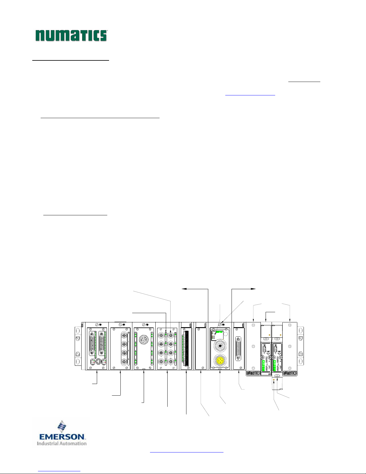
Below is an example of a 2012 series valve manifold. This fieldbus manifold series is capable of addressing a
total of 224 I/O. The manifold can be viewed as having two sections to it, the
. The
Side
Valve Side
supports a maximum of 32 solenoid coils and the
maximum of 6 modules totaling 192 Outputs, 96 Inputs, or various combinations. The communication
module has two connectors: a 5-pin communication connector and a 4-pin power connector. The
communication connector either comes in a 12mm micro connector for 1.5 Mbps or a 12mm reverse key micro
connector for 1.5 thru 12 Mbps. Pin-outs for these, along with I/O connectors, and are labeled on the side of
the respective modules.
Discrete I/O
LED Status
Indicator(s)
Connectors
I/O Point
Discrete I/O Side
(Maximum of 6 Modules)
Status LED's
(Maximum of 32 Solenoids)
Module/
Network
Valve Side
Discrete I/O Side
Valve Side
Chassis Ground
Connection
Valve
End Plates
Valve
and the
Discrete I/O
supports a
Dual 25 Pin Sub-D
w/Aux Power
Output Module
Analog Module
19 Pin Round
Connector Module
Page 1
8 Connector I/O Module
Terminal Strip Module
TDG22PTQS2-0
Manual Configuration
Module (MCM)
1/07
Subject to change without notice
www.numatics.com/fieldbus
BUS ERROR
MOD STATUS
Profibus-DP
FUSE 1
+24V VLV/OUT
FUSE 2
+24V NODE/IN
Communications
Module (Node)
Valve Side
Sub-D Output
Module
Manual
Override
Solenoid LED
Status Indicator
Page 2
G2-2 Series Profibus-DP Quick Start Manual
3) MCM - Manual Configuration Module
Rotary Switch
(SW4)
Rotary Switch
(SW3)
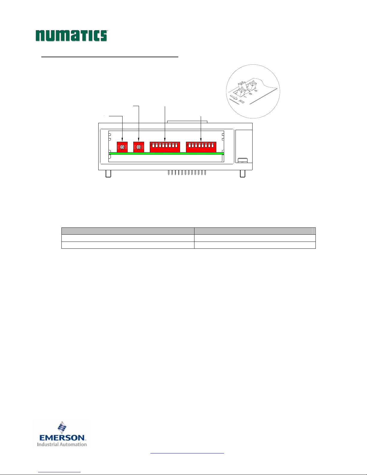
The MCM is the module that allows the user to manually set address and other user definable options. The
MCM consists of two DIP switch sets (SW1 and SW2) and two rotary switches (SW3 and SW4).
MCM Module Part Numbers
Description Part Number
Complete Module 239-1384
Replacement Board 256-684
DIP Switch
(SW2)
325
1
ON
All DIP switches shown in the "OFF" position
(Optional when using Class 2 Profibus-DP Master)
DIP Switch
(SW1)
4
8
6 7
4
325
1
6 7 8
ON
Page 2
TDG22PTQS2-0
1/07
Subject to change without notice
www.numatics.com/fieldbus
Page 3
ettings
G2-2 Series Profibus-DP Quick Start Manual
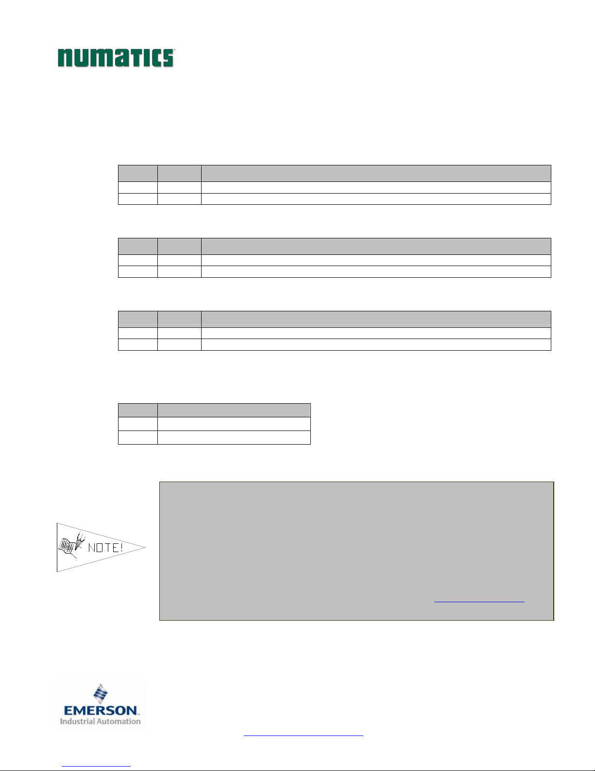
MCM Settings
DIP Switch Settings (SW1) – No Function
DIP Switch Settings (SW2)
Node Address – Hundreds Digit:
Switch Setting Description
SW2-1 Off Hundreds digit off
SW2-1 On* Hundreds digit on (add 100 to rotary switch setting)
Manual or Software Configuration:
Switch Setting Description
SW2-2 Off* Address set manually using MCM Configuration
SW2-2
Node Address Reset:
Switch Setting Description
SW2-8 Off* No change to address retained in flash memory
SW2-8
Rotary Switch Settings (SW3 and SW4)
Node Address:
Switch
SW3 Sets the Ones Digits
SW4 Sets the Tens Digits
On Address set in software when using Class 2 Profibus-DP Master
On Node address in flash memory is set to 126 on next power up cycle
Description
* Factory Default S
•
•
•
•
Page 3
All DIP and rotary switch settings do not take effect until power is cycled
(turned OFF and ON).
Baud rate in Profibus-DP slaves is automatically configured.
Node address may only be assigned once per network.
GSD files may be downloaded from our web site at www.numatics.com.
TDG22PTQS2-0
Subject to change without notice
www.numatics.com/fieldbus
1/07
Page 4
Testing
G2-2 Series Profibus-DP Quick Start Manual
4) Self-Test Mode
An internal diagnostic tool can also be enabled using the optional MCM module. This tool allows the user to
confirm that all of the Inputs and Outputs on the manifold are fully functional without needing a network
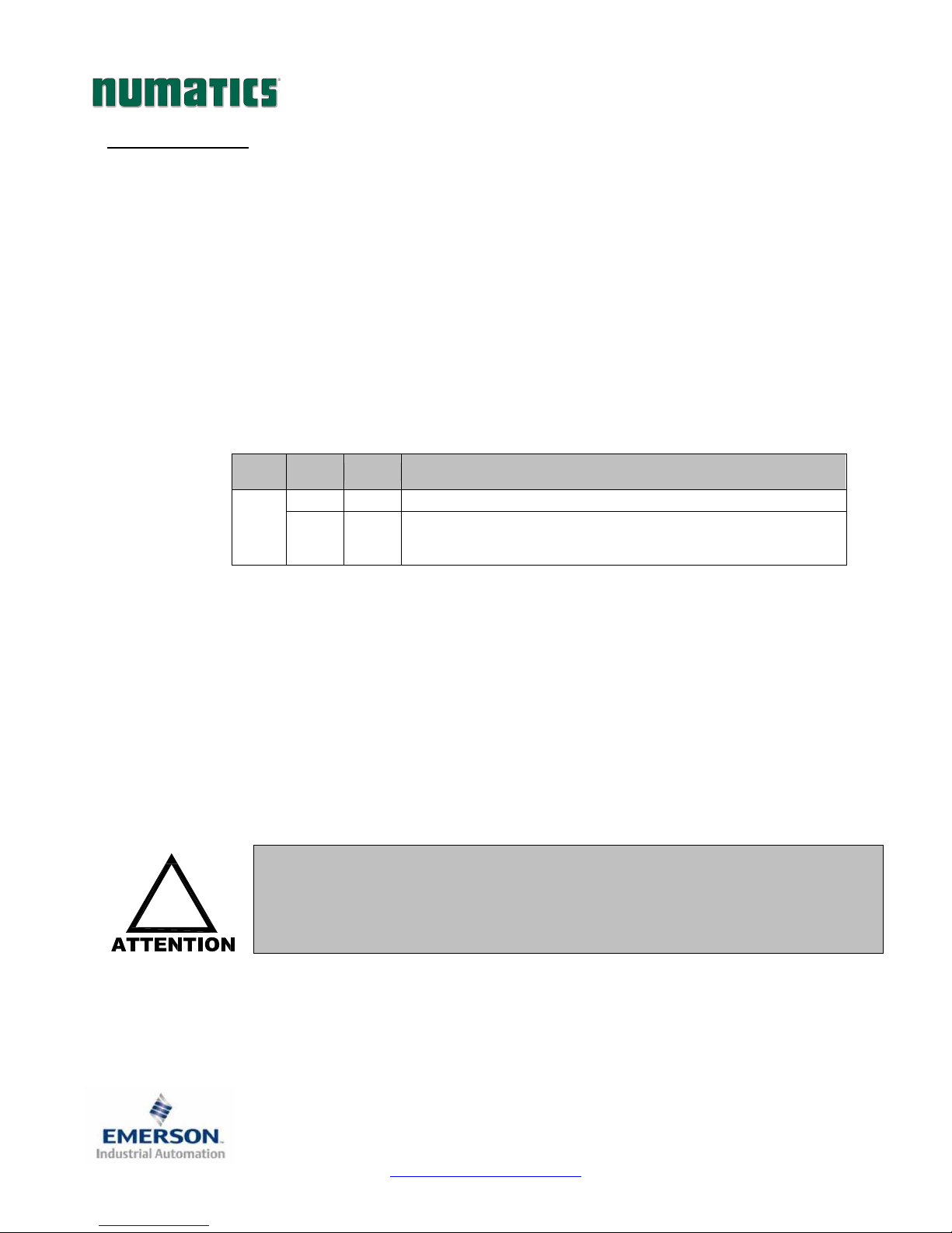
connection or controller. There are two test modes that the user can choose using SW2-8. The “Output” test
mode tests all the outputs by sequentially turning them ON one at a time. The “Input/Output” test mode
tests the inputs by causing all of the outputs to toggle between even and odd values when any input is made.
To use the Self-Test Mode, the user must first set some initial conditions using the MCM module. Follow
these steps to obtain the needed initial condition settings. Remember to remove power from the manifold
before making changes to the MCM when setting these initial conditions.
1) Disconnect power and air from the manifold!
2) Record current MCM settings.
3) Set the rotary switches to 99 (SW3 and SW4).
4) Make sure that SW1-5, SW2-1, and SW2-7 are in the “ON” position.
5) Select the desired test mode with SW2-8 (see table below)
Switch
SW2-8
6) Make sure that all of the other switches are in the “OFF” position.
The initial conditions are now set. To enable the Self-Test Mode, apply power to the manifold and make the
following changes while the module status LED is blinking (within 5 to 10 seconds of power up):
Once Self-Test Mode is enabled, the Bus Error LED will flash red/green until Self-Test Mode is terminated by
removing power to the unit. Remember to return the MCM settings to their original settings to return the
communication node to normal operation.
!
Mode
Output Off Sequentially turns all the outputs ON and OFF.
Input/
Output
•
•
Setting
Causes all of the odd outputs to come on and stay on until an
On
1) Set SW2-6 to the “ON” position.
2) Set SW2-7 to the “OFF” position.
input is made. When an input is made, the outputs will toggle to
the even outputs.
Description
Air should be disconnected to the manifold when attempting to run the
Self-Test Mode to prevent unwanted motion.
Communication lines should be disconnected before attempting to run the
Self-Test Mode.
Page 4
TDG22PTQS2-0
Subject to change without notice
www.numatics.com/fieldbus
1/07
Page 5
G2-2 Series Profibus-DP Quick Start Manual
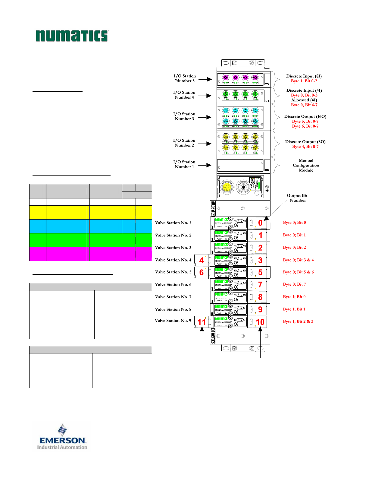
5) I/O Mapping Example
Example:
Assumed Settings
- Single Z-Boards
valves
- Double Z-Boards
valves
- Valve Output Configuration = 32 Coils
TM
used with single solenoid
TM
used with double solenoid
Discrete I/O Configuration
Pos
No.
Module Type Part No.
1 MCM 239-1384 -- --
8O Sourcing
2
16O Sourcing
3
4
5
(PNP)
(PNP)
4I Sinking
(NPN)
8I Sinking
(NPN)
239-1315 0 1
239-1319 0 2
239-1304 1 0
239-1308 1 0
Manifold I/O Configuration
Outputs and Mapping Location
Valve Outputs = 12
Allocated Unused
Valve Outputs = 20
Discrete Outputs = 24
Total Outputs = 56
Byte 0; Bits 0-7
Byte 1; Bits 0-3
Byte 1; Bits 4-7
Bytes 2 - 3; Bits 0-7
Bytes 4,5 and 6;
Bits 0-7
Inputs and Mapping Location
Discrete Inputs = 12
Allocated and
Reserved Inputs = 4
Total Inputs = 16
Byte 0; Bits 0-7,
Byte 1; Bits 0-3
Byte 1; Bits 4-7
In Out
Bytes
When the 12 End
Solenoid is
energized, the 2 port
is pressurized.
When the 14 End
Solenoid is
energized, the 4 port
is pressurized.
Page 5
TDG22PTQS2-0
Subject to change without notice
www.numatics.com/fieldbus
1/07
Page 6
G2-2 Series Profibus-DP Quick Start Manual
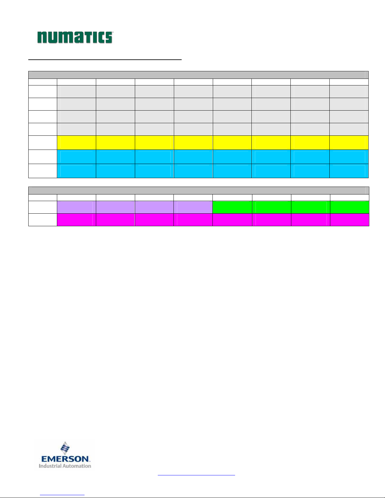
I/O Mapping Table Example Continued
Output Table
BYTE Bit 7 Bit 6 Bit 5 Bit 4 Bit 3 Bit 2 Bit 1 Bit 0
0
1
2
3
4
5
6
Valve Coil
No. 8
Allocated &
Reserved
Allocated &
Reserved
Allocated &
Reserved
Discrete
Output No. 7
Discrete
Output No. 7
Discrete
Output No. 15
BYTE Bit 7 Bit 6 Bit 5 Bit 4 Bit 3 Bit 2 Bit 1 Bit 0
0
1
Allocated &
Reserved
Discrete
Input No. 7
Valve Coil
No. 7
Allocated &
Reserved
Allocated &
Reserved
Allocated &
Reserved
Discrete
Output No. 6
Discrete
Output No. 6
Discrete
Output No. 14
Allocated &
Reserved
Discrete
Input No. 6
Valve Coil
No. 6
Allocated &
Reserved
Allocated &
Reserved
Allocated &
Reserved
Discrete
Output No. 5
Discrete
Output No. 5
Discrete
Output No. 13
Allocated &
Reserved
Discrete
Input No. 5
Valve Coil
No. 5
Allocated &
Reserved
Allocated &
Reserved
Allocated &
Reserved
Discrete
Output No. 4
Discrete
Output No. 4
Discrete
Output No. 12
Input Table
Allocated &
Reserved
Discrete
Input No. 4
Valve Coil
No. 4
Valve Coil
No. 12
Allocated &
Reserved
Allocated &
Reserved
Discrete
Output No. 3
Discrete
Output No. 3
Discrete
Output No. 11
Discrete
Input No. 3
Discrete
Input No. 3
Valve Coil
No. 3
Valve Coil
No. 11
Allocated &
Reserved
Allocated &
Reserved
Discrete
Output No. 2
Discrete
Output No. 2
Discrete
Output No. 10
Discrete
Input No. 2
Discrete
Input No. 2
Valve Coil
No. 2
Valve Coil
No. 10
Allocated &
Reserved
Allocated &
Reserved
Discrete
Output No. 1
Discrete
Output No. 1
Discrete
Output No. 9
Discrete
Input No. 1
Discrete
Input No. 1
Allocated &
Allocated &
Output No. 0
Output No. 0
Output No. 8
Input No. 0
Input No. 0
Valve Coil
No. 1
Valve Coil
No. 9
Reserved
Reserved
Discrete
Discrete
Discrete
Discrete
Discrete
Page 6
TDG22PTQS2-0
1/07
Subject to change without notice
www.numatics.com/fieldbus
Page 7
G2-2 Series Profibus-DP Quick Start Manual
6) Output Short Circuit Protection (Status Input Bits)
Status Input Bits report the integrity of the load being driven by the output driver. They must be mapped to the
scanner as part of the Input Size Value. Please refer to the table below for Status Input Bit action during fault
condition:
Output Type Output State Fault Condition Status Bit
Valve Solenoid Coil Driver or
Sinking (NPN)
Discrete Outputs
Discrete Outputs
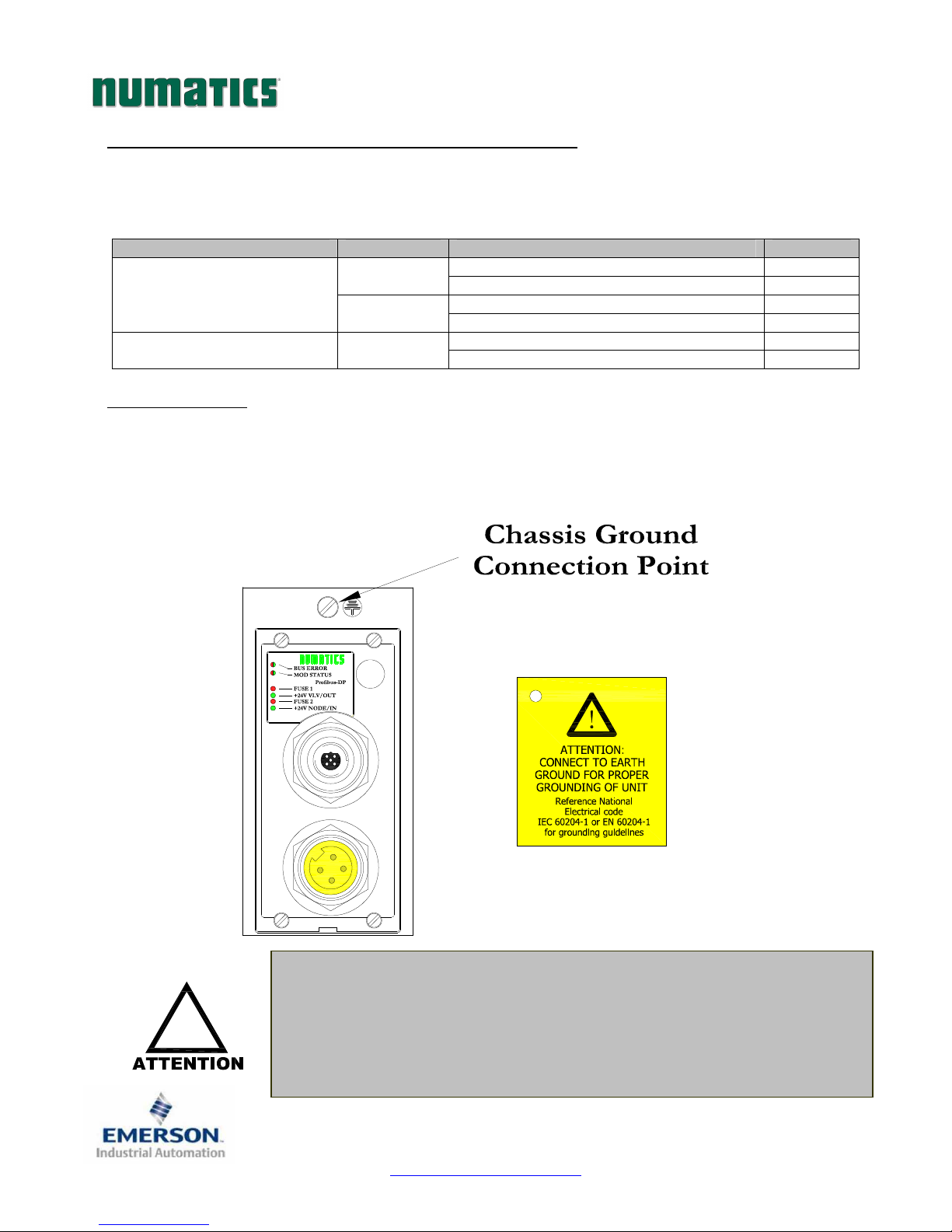
7) Ground Wiring
All Numatics Inc. communication nodes should be grounded during the installation process. These grounding
guidelines can be found in National Electrical code IEC 60204-1 or EN 60204-1. There also is a,
“ATTENTION: CONNECT TO EARTH GROUND FOR PROPER GROUNDING OF UNIT”, label
attached to the chassis ground connection point on the G2-2 series communication node housing. This label
also points out where the grounding guidelines can be found.
!
ON
OFF
ON
•
Proper grounding will alleviate and prevent many intermittent problems
with network communication.
•
When grounding to a machine frame, please ensure that the machine frame
itself is already properly grounded.
•
Better grounding can be achieved when larger diameter (lower gauge) wire
is used.
No Fault
Fault No Fault
Fault No Fault 0 Sourcing (PNP)
Fault -
Short Circuit, Over Temp/Over Current
Open Load
1
Short Circuit, Over Temp/Over Current
1
1
0
0
Page 7
TDG22PTQS2-0
Subject to change without notice
www.numatics.com/fieldbus
1/07
Page 8
G2-2 Series Profibus-DP Quick Start Manual
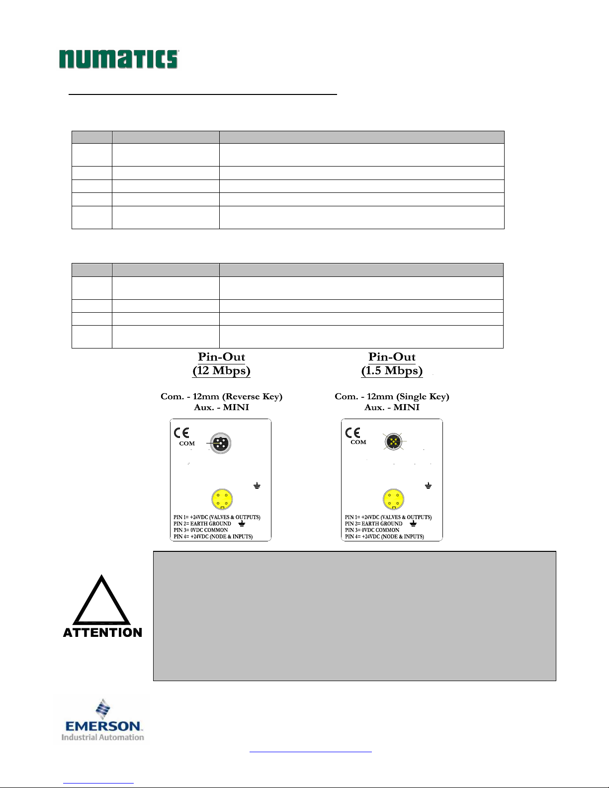
8) Communication Module Connector Pin-Outs
Profibus-DP Communication Connector Pin-Out
Pin No.
1 +5 VDC
2 Data Line A Profibus-DP Communication Line A (Green)
3 0VDC Common Common for +5V output and Data Lines A & B
4 Data Line B Profibus-DP Communication Line B (Red)
5 Earth Ground
Auxiliary Power Connector Pin-Out
Pin No.
1
2 Earth Ground Protective Earth (Case Ground)
3 0VDC Common 0VDC Common, for Valves, I/O, and Node Power
4
!
Function Description
+5 volt output from node, used for termination of network or
auxiliary devices.
Internally connected to earth ground (case). Connect to shield of
Profibus-DP cable.
Function Description
+24VDC
(Valves and Outputs)
+24VDC
(Node and Inputs)
Profibus DP (12 Mbps)
PIN 1= +5VDC
PIN 2= DATA LINE A
PIN 3= COMMON 0VDC
PIN 4= DATA LINE B
PIN 5= EARTH GROUND
AUX MALE
•
Voltage Used to Power Outputs
(Valve Coils and Discrete Outputs)
Voltage Used to Power Discrete Inputs and Node Electronics
1 2
5
4
3
4
FEMALE
3
2
1
Maximum current capacity on the 0VDC common pin of the auxiliary
power connector is 8 Amps. The combined draw of the +24VDC Valves and
Outputs and +24VDC Node and Inputs pins cannot exceed 8 Amps, at any
given moment in time.
•
The auxiliary power +24VDC Node and Inputs pin supplies power to the
node electronics. This pin must be powered at all times for communication
node to be functional.
•
Internal node electronics support all Profibus-DP communication baud
rates of 9.6kBit/s thru 12Mbit/s. Only Comm. Connector types differ.
Profibus DP (1.5 Mbps)
4
3
5
MALE
2
1
PIN 1= +5VDC
PIN 2= DATA LINE A
PIN 3= COMMON 0VDC
PIN 4= DATA LINE B
PIN 5= EARTH GROUND
AUX MALE
2
3
14
Page 8
TDG22PTQS2-0
1/07
Subject to change without notice
www.numatics.com/fieldbus
Page 9
G2-2 Series Profibus-DP Quick Start Manual
9) LED Functions
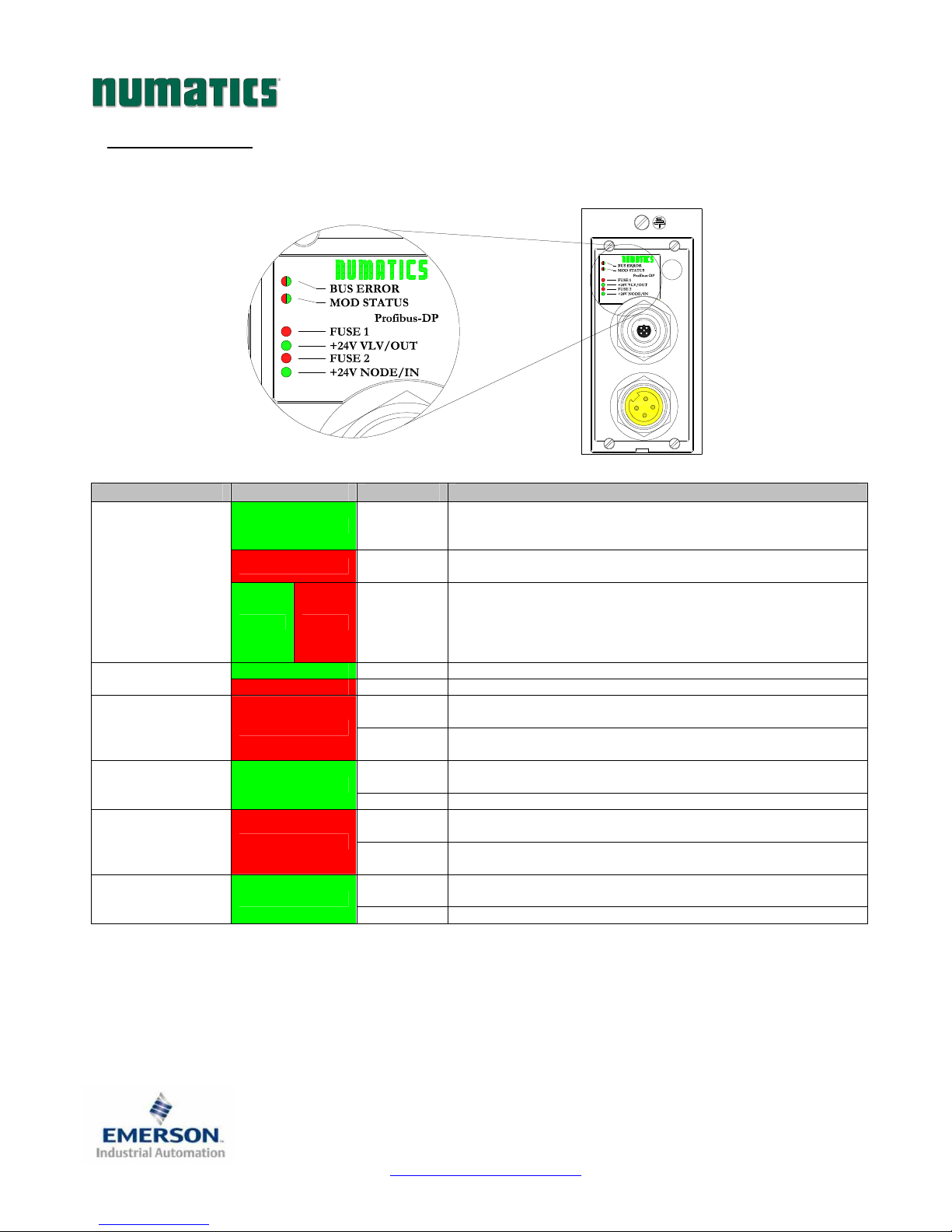
Upon power up, the LEDs indicate the status of the unit. There are six LEDs on the G2-2 Profibus-DP node;
one for Bus Error, one for Mod Status, two for internal fuse integrity, and two for Aux. Power status.
LED Name Color Status Description
Normal operation. The bus link is OK. Baud rate detected,
BUS ERROR
Green Red FLASHING
(Module Status)
FUSE 1 Red
FUSE 2 Red
Green ON
Red ON
Green ON Normal operation. Node hardware OK. MOD STATUS
Red ON Critical hardware fault. The microprocessor is not running.
OFF
ON
OFF
ON DC Power applied to
OFF
ON
OFF
ON DC Power applied to
parameterization and configuration OK; Unit is in data exchange
mode.
Bus Error. Bus connection failed or off-line; Invalid
parameterization or configuration.
The module configuration (I/O and valves) in the user application
is different than the physical configuration of the manifold (If
manifold is online).
Module is in self-test mode (If manifold is Offline).
Internal fuse
+24V
Internal fuse F1 is open; No power is internally provided to valves or
outputs. Communication NOT affected.
No DC Power present at
connector. +24V VLV/OUT Green
Internal fuse F2 is OK (valid only when power is applied to
+24V
Internal fuse F2 is open; No power is internally provided to node
electronics or inputs. Communication Node will not function.
No DC Power present at
connector. +24V NODE/IN Green
VLV / OUT
NODE / IN
F1
is OK (valid only when power is applied to
pin on Aux. Power connector).
+24V
+24V
pin on Aux. Power connector.
+24V
+24V
VLV / OUT
VLV / OUT
NODE / IN
NODE / IN
pin on Aux. Power
pin on Aux. Power Connector.
pin on Aux. Power
pin on Aux. Power connector.
Page 9
TDG22PTQS2-0
1/07
Subject to change without notice
www.numatics.com/fieldbus
Page 10
G2-2 Series Profibus-DP Quick Start Manual
10) Factory Default Settings
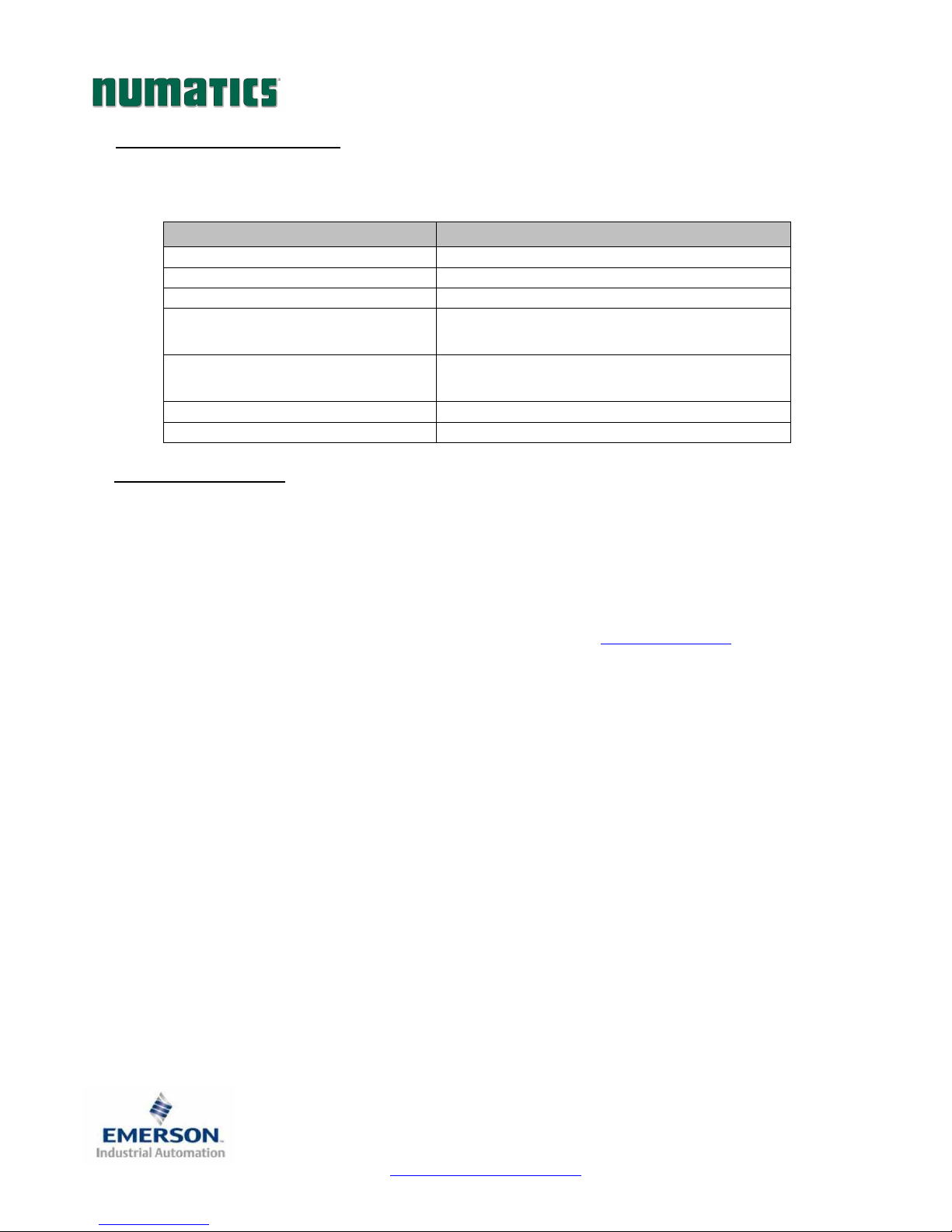
Unless otherwise requested, all standard G2-2 Series Profibus-DP manifolds ship with specific factory default
settings. Below is a list of the factory default settings:
Description Default Settings
Node Address 126
Address Reset No change to address retained in flash memory
Manual or Software Configuration Node address set manually with MCM
Input Module Power Jumper
+24VDC Node and Inputs pin on the Aux. power connector)
Output Module Power Jumper
+24VDC Valves and Outputs pin on the Aux. power connector)
Valve Side Output Bytes 4 Bytes (32 Allocated Valve Coil Outputs)
Discrete I/O Side - I/O Bytes Self-Configuring based on the I/O modules installed.
11) Technical Support
For technical support, contact your local Numatics distributor. If further information is required,
please call Numatics Inc. at (248) 887-4111 and ask for Technical Support.
Issues relating to network set-up, PLC programming, sequencing, software related functions, etc…
should be handled with the appropriate product vendor.
Information on device files, technical manuals, local distributors, and other Numatics, Inc. products
and support issues can be found on the Numatics, Inc’s. WEB site at www.numatics.com
(Input sensor power supplied by
(Output module power supplied by
PU
SP
TDG22PTQS2-0
Subject to change without notice
Page 10
www.numatics.com/fieldbus
1/07
 Loading...