

Page 1
E22 Operation Manual
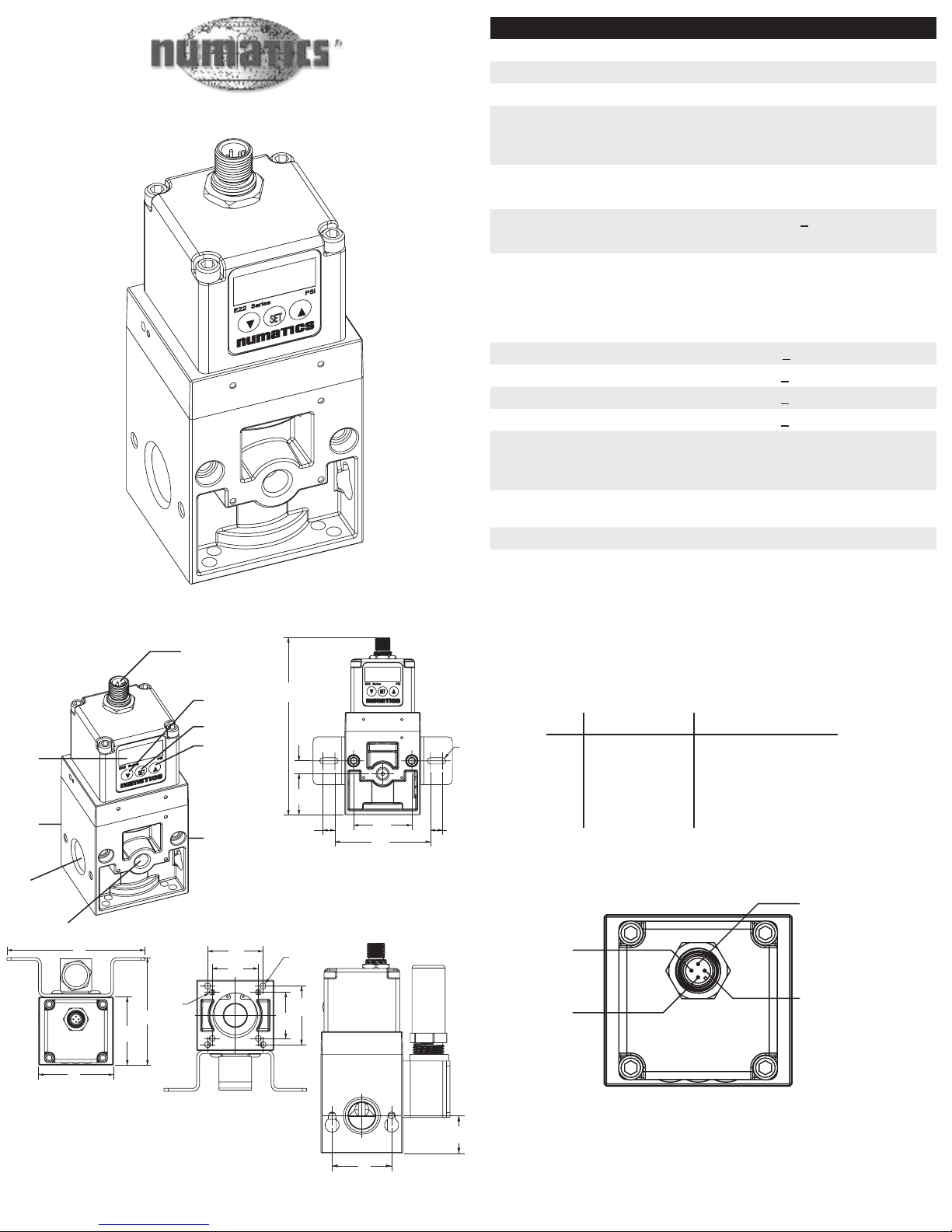
Inlet
Port
Gauge
Port
Exhaust
Port
(not visible)
LED
Display
M12 4 pin Micro
Connector
Down Arrow
Button
Set Button
Up Arrow
Button
Outlet
Port
(not visible)
Command Source
Power Source
1
1
2
3
4
2
3
4
+
+
Monito
r
+24VDC
0VDC
Co
mmon
Common
0VDC
1.29
(33)
.41
(10)
1.83
(46)
5.571
(141.5)
3.00
(76)
.38
(10)
.38
(10)
.10
(3)
2.38
(60)
2.17
(55)
3.42
(87)
4.38
(111
)
1.420
(36.1)
1.420
(36.1)
.185
(4.7)
.190
(4.8)
1.800
(45.7)
1.700
(42.2)
1.58
(40)
1.00
(25)
Pin 4
Monitor
Outpu
t
Pin
1
+24VDC
Pin
3
Common
0VDC
Pin
2
Command
SPECIFICATIONS
Minimum Supply Pressure Set Pressure + 15 PSI (1 BAR)
Maximum Supply Pressure
150 PSI (10 BAR)
Regulating Pressure Range 0-100 PSI
Power Supply
Voltage
Current
24V DC ±10%
0.04 A
Consumption
Input Signal
Input
Impedance
Monitor Output
Current 4-20mA
Voltage 0-5VDC, 0-10VDC
Current < 250 Ω
Voltage
Analog
Output
4.8 KΩ
0-5VDC
0-10VDC
4-20mA
Pressure
24VDC (PNP)
Achieved
Linearity
< ±1% of span
Hysteresis < ±.5% of span
Repeatability < ±.5% of span
Sensitivity < ±.2% of span
Output
Display
Accuracy ±.5% PSIG
Minimum unit PSI 0.1, BAR 0.01, kPa 001.,
kgf/cm² 0.01
Temperature Range
40-120°F
4-50°C
Enclosure IP65 Equivalent/NEMA 4
Weight
1.4lbs (0.64kg)
Dimensions:
3 4
2
PIN Euro Color Code Description
1 Brown Supply Power +24VDC
2 White Command Signal
3 Blue Common 0 VDC
4 Black Monitor Output
Page 2
Initial Settings
E22 Series PSI
100%
50
0
4mA
0VDC
0VDC
20mA
10VDC
5VDC
100%
50
0
4mA
0VDC
0VDC
20mA
10VDC
5VDC
100%
50
0
4mA
0VDC
0VDC
20mA
Fa
st
Accurate
10VDC
5VDC
100%
50
0
4mA
0VDC
0VDC
20mA
10VDC
5VDC
E22 Series PSI
E22 Series PSI
E22 Series PSI
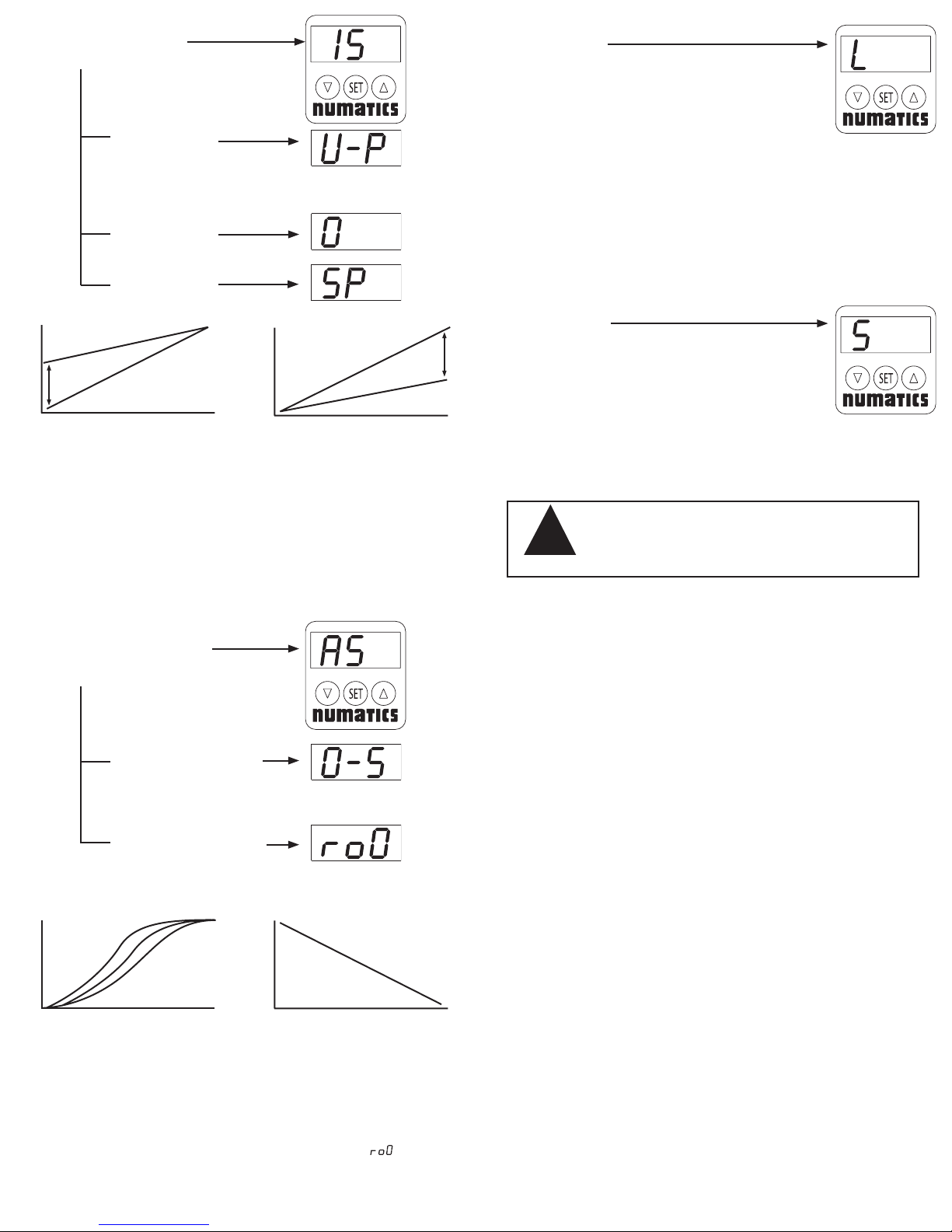
Mode
(Hold SET for 3 sec)
Units:
P= PSI
B= BAR
A = Kpa
F = Kgf/cm²
Zero Setting
Span Setting
Locked
Mode
Press and hold the up and down
arrow buttons for 10 seconds to
activate the locked mode with will
be displayed by a “L”. To unlock the
display, press and hold the up and
down arrow buttons for 10 seconds
until the “U” is displayed.
Adjusting Zero Setting Adjusting Span Setting
Hold the set button for 3 seconds or until “IS ” is displayed. Once the set button is
released the unit of measure is displayed as “U‐ P ”. To select the desired unit, scroll
using the up or down arrow buttons. Once the appropriate unit is displayed, press
the set button, which prompts the zero setting. This is shown by flashing between
a left justified zero and a right justified setting. Use the up or down arrow buttons to
select the desired minimum pressure. Press the set button to store the zero setting
and prompts the span setting shown by flashing between “SP ” and the setting. Use
the up or down arrow buttons to select the span setting. Finally press the set button
to store the span setting and return to normal operation.
5 6
Advanced Settings
Mode
(Hold SET for 10 sec)
Operation Mode:
S= Standard
F= Fast
A= Accurate
Reverse Function:
0= off
1= on
Operation Modes Reverse Function
Self-Test
Mode
Push and hold the SET button
before power is applied. Continue
to hold the SET button for 3
seconds after power is applied.
Push and hold the UP and DOWN
buttons for 10 seconds.
Self-Test Mode will cause output pressure to
change without a command signal. This may
!
Attention
cause unexpected motion or/ and unsafe
conditions
Notes:
1. This product is not intended to be used as a saftey device to protect life or
prevent injury.
2. Misapplication of this product could result in injury or equipment damage.
3. Supply air must be filtered to 5
4. Before installation, flush piping to insure that it is free of oil, pipe scale, rust, etc.
5. When using sealing tape, leave 1 ½ or 2 threads bare to prevent contamination.
6. Operating device without supply pressure for prolonged periods of time could
result in internal damage.
7. When the monitor output is not used, use proper shielding to protect the contact.
8. Unless otherwise specified, when power is removed from the unit, output
pressure will remain at the last commanded pressure, until supply pressure is
removed.
µ or less and free of moisture and lubricants.
Hold the set button for 10 seconds or until “AS ” is displayed. Once the set button
is released the operation mode is displayed as “0 ‐ S”. Use the up or down arrow
buttons, to select the optimal operation mode. The best mode will be determined by
the application. Generally, the accurate mode should be used when response time
is less critical than accuracy and the fast mode should be used when the response
time is more critical than accuracy. Press the set button to store the appropriate
operation mode and prompts the reverse function, displayed as “ ”. Use the up
or down arrow buttons to turn the reverse function on or off. Finally, press the set
button to store the reverse function and return to normal operation
7 8
9. After the zero setting has been changed, the regulator will output that pressure
after pressing the set button, even if there is no command signal present.
10. Disassembling of this unit will void all warranties.
TDE22A-1.0 - 4/27/2005
 Loading...