

Numatic TTB 2120/100T, TTB 2120/120T Owner's Manual

www.nacecare.com
Owner Instructions
Mode d’emploi
Original Instructions
Warning! Read instructions before using the machine.
Attention
Lisez la notice avant d’utiliser la machine.
TTB 2120/100T
TTB 2120/120T
Ride - On Scrubber Dryer
Autolaveuse à siège

2
Index Page 2 Index Page 2
Machine Overview Page 3 Description de la machine Page 27
Control Panel Overview Page 4 Description du panneau de commande Page 28
Rating label / Personal
Protective Equipment /
Recycling
Page 5
Plaque signalétique / Équipement de protection
individuelle /
Recyclage
Page 29
Safety Precautions Page 6 Précautions à prendre Page 30
Quick set-up guide Page 7 Guide d’installation rapide Page 31
Machine Set-up Préparation de la machine
Raise / Lower the Floor-tool Page 8 Relèvement / abaissement du suceur Page 32
Fitting the Floor-tool Page 8 Montage du suceur Page 32
Breakaway Floor-tool
feature
Page 8 Fonction de détachement du suceur Page 32
Raise / Lower the Brush
Deck
Page 9
Relèvement /abaissement
du plateau de brosses
Page 33
Fitting the Brush Page 9 Montage de la brosse Page 33
Floor-tool transit bracket Page 9 Support de transit du suceur Page 33
Filling the clean-water tank Page 10 Remplissage du réservoir d’eau propre Page 34
Fill Level Indicator Page 10 Indicateur du niveau de remplissage Page 34
Machine Operation Fonctionnement de la machine
Pre-cleaning advice Page 11 Conseils de pré-nettoyage Page 35
Setting the cleaning
controls
Page 11 Réglage des commandes de nettoyage Page 35
Waste water tank full Page 11 Réservoir d’eau sale plein Page 35
Brush pressure Page 12 Pression de la brosse Page 36
Emergency stop button and
horn
Page 12 Bouton d’arrêt d’urgence et klaxon Page 36
Anti-tip System Page 12 Système antibasculement Page 36
Machine usage advice Page 13 Conseils d’utilisation de la machine Page 37
Maximum Speed Control Page 13 Commande de la vitesse maximale Page 37
Hose U-Bend Clip Page 14 Collier de repli du tuyau Page 38
Off-aisle cleaning kit (op-
tional)
Page 14 Kit de nettoyage hors-allée (en option) Page 38
Machine Cleaning Nettoyage de la machine
Tanks and Filters Page 15 Réservoirs et ltres Page 39
Floor-tool cleaning and
blade replacement
Page 17 Nettoyage du suceur et remplacement des lamelles Page 41
Machine Charging Page 19 Charge de la machine Page 43
Free-wheel function Page 20 Fonction roues libres Page 44
Battery care Page 20 Entretien de la batterie Page 44
Trouble-shooting Page 22 Dépannage Page 46
Schematic Page 24 Schémas Page 48
Specications Page 25 Specications Page 49
3
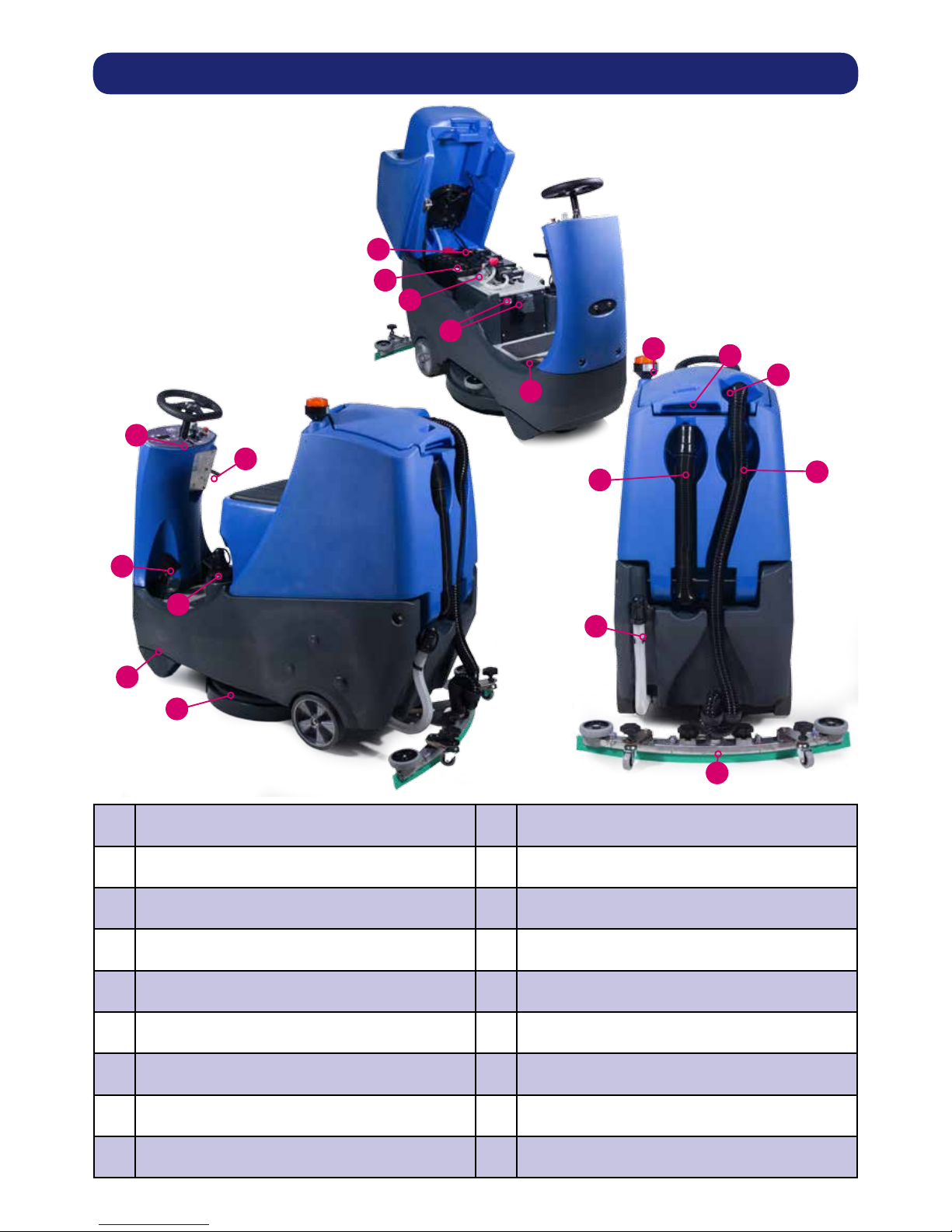
Machine Overview
1
Operator control panel
10
On-board charger and charge indicator
2
Brush deck foot pedal
11
Accelerator pedal
3
Anti-tip buffers
12
Pedestrian warning light
4
Floor-tool raise / lower lever
13
Floor-tool transit bracket
5
Clean water tank ll point
14
Air separator assembly
6
Brush deck
15
Waste water emptying hose
7
40 Amp battery fuse
16
Vacuum hose
8
Gel batteries
17
Clean water tank emptying hose
9
Clean water tank lter
18
Floor-tool
10
9
8
7
6
5
4
3
2
1
11
12
13
14
15
16
17
18
4
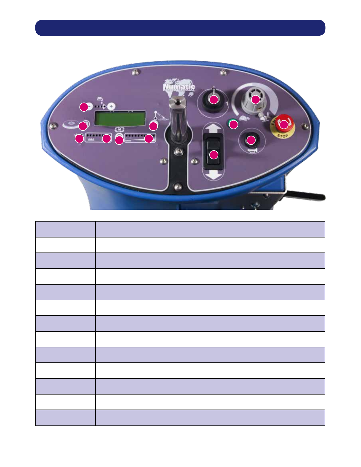
Control Panel Overview
10
9
8
654
3
2
1
1
Water Flow Rate Indicator and Selection Button
2
Brush Engage and Disengage Button
3
Service Indicator
4
Brush Pressure / Load Indicator
5
Run Time Selection Button
6
Battery Charge Level Indicator
7
Off Aisle Vacuum Button
8
On / Off Switch
9
Forward / Reverse Switch
10
LED Status Indicator
11
Maximum Speed Control
12
Horn Button
13
Emergency Stop Button
7
11
12
13
5
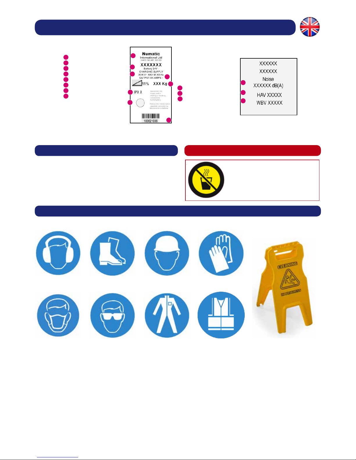
Rating Label / Personal Protective Equipment / Recycling
Safety Critical Components
PPE (Personal Protective Equipment) that maybe required for certain operations
Charging Leads: Ho5VV-F x 1.0 mm2 x 3 Core
Transaxle 205190
Battery Charger (230V)
(115V)
Ear Protection Safety HatSafety Footwear Safety Gloves
Face Mask Eye Protection Protective Clothing Hi Viz Jacket Caution Floorsign
NOTE: A risk assessment should be conducted to determine which PPE should be worn.
Caution
No HOT drinks
when operating this
machine.
1
2
3
4
5
6
7
8
Rating Label
Company Name & Address
Machine Description
Voltage Frequency
Power rating
Weight (ready to use)
Ingress Protection
Approval Mark
Machine yr/wk Serial number
1
2
3
4
5
6
7
8
9
9
Noise level
Hand arm vibration
Whole body vibration
10
11
11
10

6
Safety Precautions
Caution
Read the instruction manual before using the appliance.
The TTB is a class 1 product when tted with an AC supply lead, but a class 3 product during normal use.
Note
This product meets the requirements of CAN/CSA-C22.2 No. 60335-1-11. IEC 60335-2-72:2002
This machine is also suitable for commercial use, for example in hotels, schools, hospitals, factories, shops and ofces for other than normal
housekeeping purposes.
Never attempt to ll the machine’ s water tanks whilst it is charging.
Machines left unattended shall be secured against unintentional movement.
Care should be taken in the choice of chemicals, detergents and other liquids. Consult your supplier.
Do’s and Don’ts
DO ensure only competent persons unpack/assemble the machine.
DO keep your machine clean.
DO keep your brushes in good condition.
DO replace any worn or damaged parts immediately.
DO regularly examine the charger lead for damage, such as cracking or ageing. If damage is found, replace the lead before further use.
DO only replace the charger lead with the correct Numatic approved replacement part.
DO ensure that the work area is clear of obstructions and / or people.
DO ensure that the working area is well illuminated.
DO pre-sweep the area to be cleaned.
DON’T use steam cleaners or pressure washers to clean the machine or use in the rain.
DON’T Don’t attempt machine maintenance or cleaning unless the power plug has been removed from the supply outlet,
if the machine is in charge mode or remove the key if in normal use.
DON’T allow any inexperienced repairs. Contact your nearest service centre.
DON’T strain charger lead or try to unplug by pulling on charger lead.
DON’T leave the brush deck in the lowered position when not in use.
DON’T expect the machine to provide trouble-free, reliable operation unless maintained correctly.
DON’T run the machine over any power cables during operation.
Warning
This machine is not suitable for picking-up hazardous dust.
Do not use on surfaces having a gradient exceeding that marked on the appliance.
As with all electrical equipment care and attention must be exercised at all times during its use, in addition to ensuring that routine and
preventative maintenance is carried out periodically in order to ensure its safe operation. Failure to carry out maintenance as necessary, including
the replacement of parts to the correct standard could render this equipment unsafe and the manufacturer can accept no responsibility or liability in
this respect.
When ordering spare parts always quote the Model Number / Serial Number specied on the Rating Plate.
This machine is for indoor use.
The machine is not to be used or stored outdoors or in wet conditions.
Don’t allow the machine to be used by inexperienced or unauthorised operators or without appropriate training.
Only use brushes provided with the appliance or those specied in the instruction manual. The use of other brushes may impair safety. A full range
of brushes and accessories are available for this product. Only use brushes or pads which are suitable for the correct operation of the machine for
the specic task being performed.
It is essential that this equipment is correctly assembled and operated in accordance with current safety regulations. When using the equipment
always ensure that all necessary precautions are taken to guarantee the safety of the operator and any other persons who may be affected. Wear
non-slip footwear when Scrubbing. Use a respiratory mask in dusty environments.
The machine, while charging, must be positioned so that the mains plug is easily accessible.
Remove the key from the ignition when cleaning and carrying out routine maintenance. When replacing major components the ignition key and
battery fuses MUST be removed.
When detergents or other liquids are used, read the manufacturer’s instructions.
If this product does not have a factory installed Numatic battery charger and batteries then it is the responsibility of the owner and user of the
product to ensure that the charging system and battery combination are compatible, t for purpose and safe to use.
Precautions when working with batteries
1. Always wear protective clothing e.g. face visor, gloves and overalls when working with batteries.
2. Whenever possible always use a properly designated and well-ventilated area for charging. Do not smoke or bring naked ames into the
charging area.
3. Remove any metallic items from hands, wrists and neck i.e. rings, chains etc. before working on a battery.
4. Never rest tools or metallic objects on top of the battery.
5. When charging is complete disconnect from the mains supply.
6. The machine must be disconnected from the supply when removing the battery.
7. To remove the batteries:- Disconnect machine from the mains supply (if charging), raise waste water tank and ensure batteries are isolated by
removing fuses. Disconnect hoses from separator and tanks, Undo battery terminals and remove batteries.
8. Only use genuine Numatic replacement batteries.
9. Do not allow the batteries to become fully discharged, it may not be possible to recharge them.
10. Do not allow one battery to be discharged separately to the other.
11. Do not mix batteries from different machines.
12. The batteries tted to this product are Valve Regulated Lead Acid (VRLA) gel electrolyte type. The tting of any other type of battery may cause
a safety hazard.
13. The batteries must be removed from the machine before it is scrapped.
14. Dispose of the batteries safely in accordance with local government regulations.
BATTERY CARE
1. Always recharge the batteries after use. This can be done at any time – it is not necessary to wait until they are fully discharged; they do not
develop a “memory”.
2. Leaving the charger to operate for a minimum of 4 hours after the green light has come on, at least weekly, will pro-long battery life.
3. Do not store the machine with the batteries discharged.
7
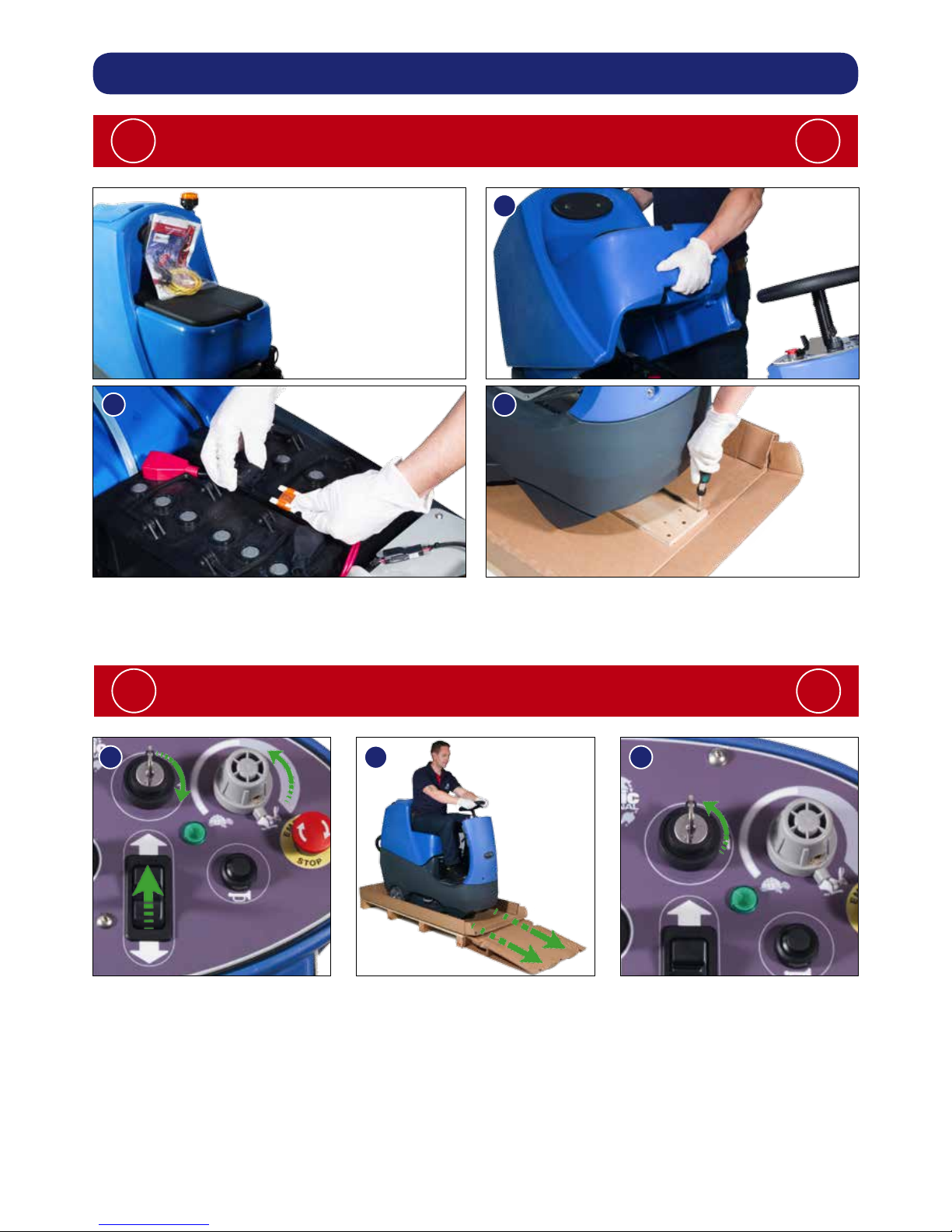
Quick Set Up Guide
After the removal of all the packaging, carefully
open and check the contents of the start up pack (Fig.1).
!
!
Lift top tank assembly to reveal battery compartment.
Always lift between points as illustrated to ensure personal safety (Fig.1).
Fit battery fuse into the battery fuse holder as illustrated (Fig.2).
Remove transit block from pallet (Fig.3).
Ensure no metal objects come into contact with battery terminals while the batteries
are exposed. When inserting the fuse you may notice a spark, this is normal.
!
!
Insert key into ignition and turn quarter-turn clockwise to the ‘ON’ (1) position, make sure that the
forward / reverse switch is set to forward and the speed control is set to low (Fig.4).
DO NOT depress accelerator pedal while software initialises.
Depress accelerator pedal with right foot and slowly drive machine off of the pallet using the ramp
provided (Fig.5).
Make sure the ramp is central to the machine and drive off straight.
Note: The seat is tted with a pressure sensor that disables the machine until an operator
is seated.
When the machine is removed and in a safe position, turn key back to the off (0) position (Fig.6).
Contents:
1 x Operator Manual
2 x Battery Charger Lead
2 x Keys
1 x 40 Amp Fuse (1 x Spare)
1 x Maxi Fuse-puller
1
2
3
456
8
Machine Set Up
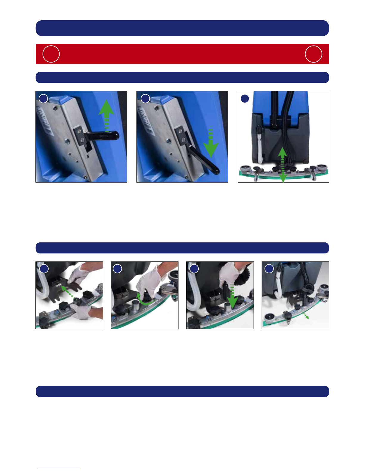
Lower the oor-tool arm by moving the oor-tool lever to the upper position (See above).
Loosen the retaining knobs on the oor-tool and slide onto the holding bracket (Fig.10).
Tighten the retaining knobs to nger tight. (Fig.11).
Push waste collection pipe onto the oor-tool; ensure a tight t (Fig.12).
Note: Raise oor-tool again before driving to the cleaning area (See Above).
Always ensure that the machine is switched off before making any adjustments
!
!
Raise / Lower the Floor-tool
To lower the oor-tool move the oor-tool lever into the upper position (Fig.7).
To raise the oor-tool move the oor-tool lever into the lower position (Fig.8).
Note: The machine will not operate in reverse with the Floor-tool lowered.
Note: The oor-tool lever guide is designed to be reversible and replaceable.
Fitting the Floor-tool
The oor-tool design incorporates a safety knock-off feature.
Allowing it to safely disengage from its mounting should it become caught on an obstruction during
forward movement (Fig.13).
Make sure you do not over tighten the retaining knobs to ensure correct operation.
Breakaway Floor-tool
798
101112
13
9
Machine Set Up
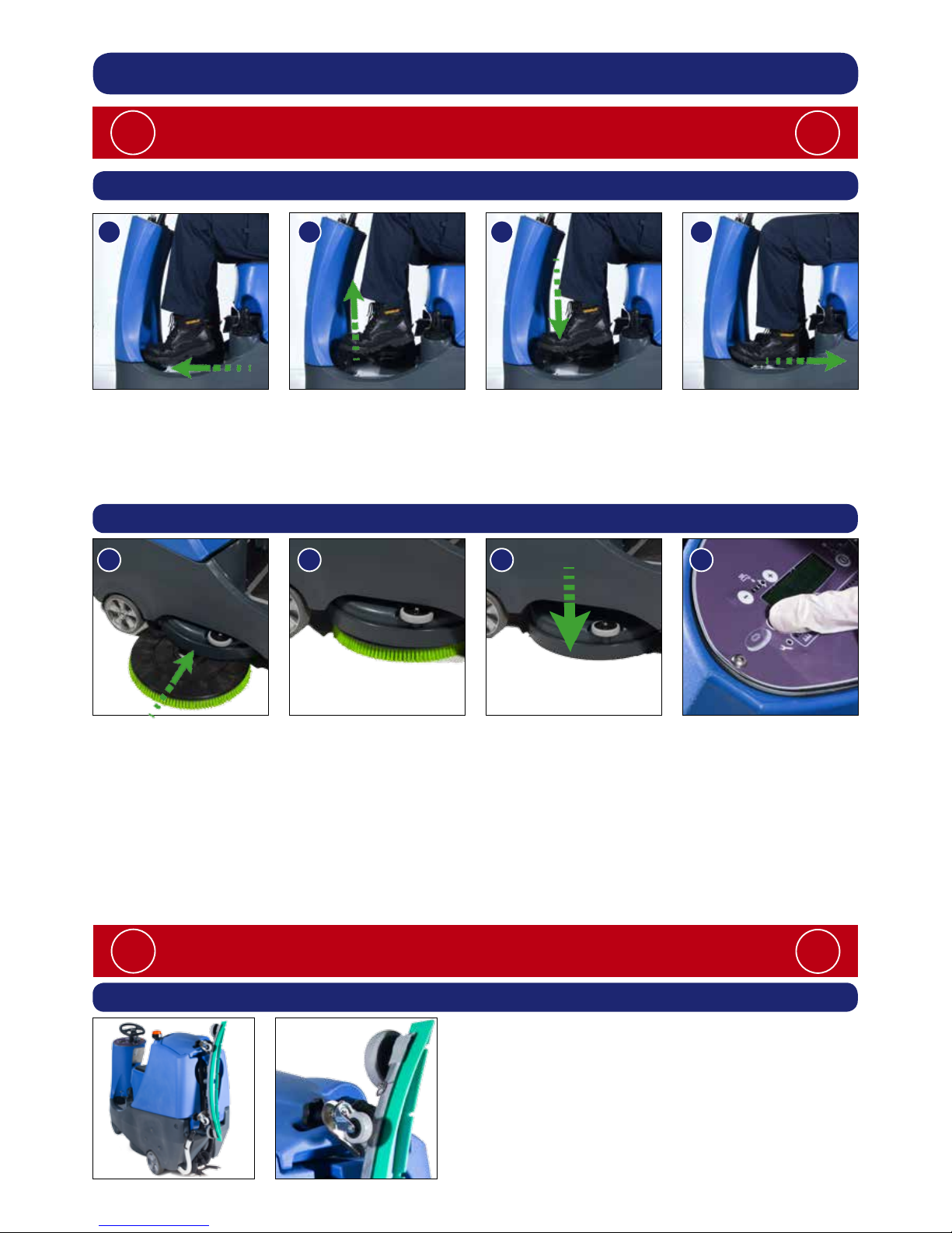
Raise / Lower the Brush Deck
To lower the brush deck slide the brush deck foot pedal forward with your foot (Fig.14) and gently
release the foot pedal (Fig.15). The brush deck is now in the lowered position.
To raise the brush deck slowly depress the foot pedal, ensuring it is in the forward position (Fig.16)
and slide your foot back to lock the pedal in place (Fig.17).
The brush deck is now in the raised position.
Fitting the Brush
Make sure the brush deck is in the raised position (see above) and place the brush under the
brush deck (Fig.18) ensuring it is central to the chuck (Fig.19), then lower the brush deck
(see above).
Turn on the machine by inserting the key and turning a quarter-turn clockwise.
Press the brush engage button and the machine will pick up the brush (Fig.21).
Turn off the machine by turning the key a quarter-turn anti clockwise.
To disengage the brush press the brush engage button with the brush deck in the raised position.
Note:
Do not lift the brush deck until the brush has stopped revolving or the brush will release.
Make sure you raise the brush deck before driving to the cleaning site.
Safety Gloves are recommended for the changing of used Brushes.
!
!
Always ensure that the machine is switched off before making any adjustments
!
!
Floor-tool Transit Bracket
When in transit, the Floor-tool can be placed on
the bracket at the rear of the machine.
Simply slot the retaining knob into the bracket.
141516
17
181920
21
10
Machine Set Up
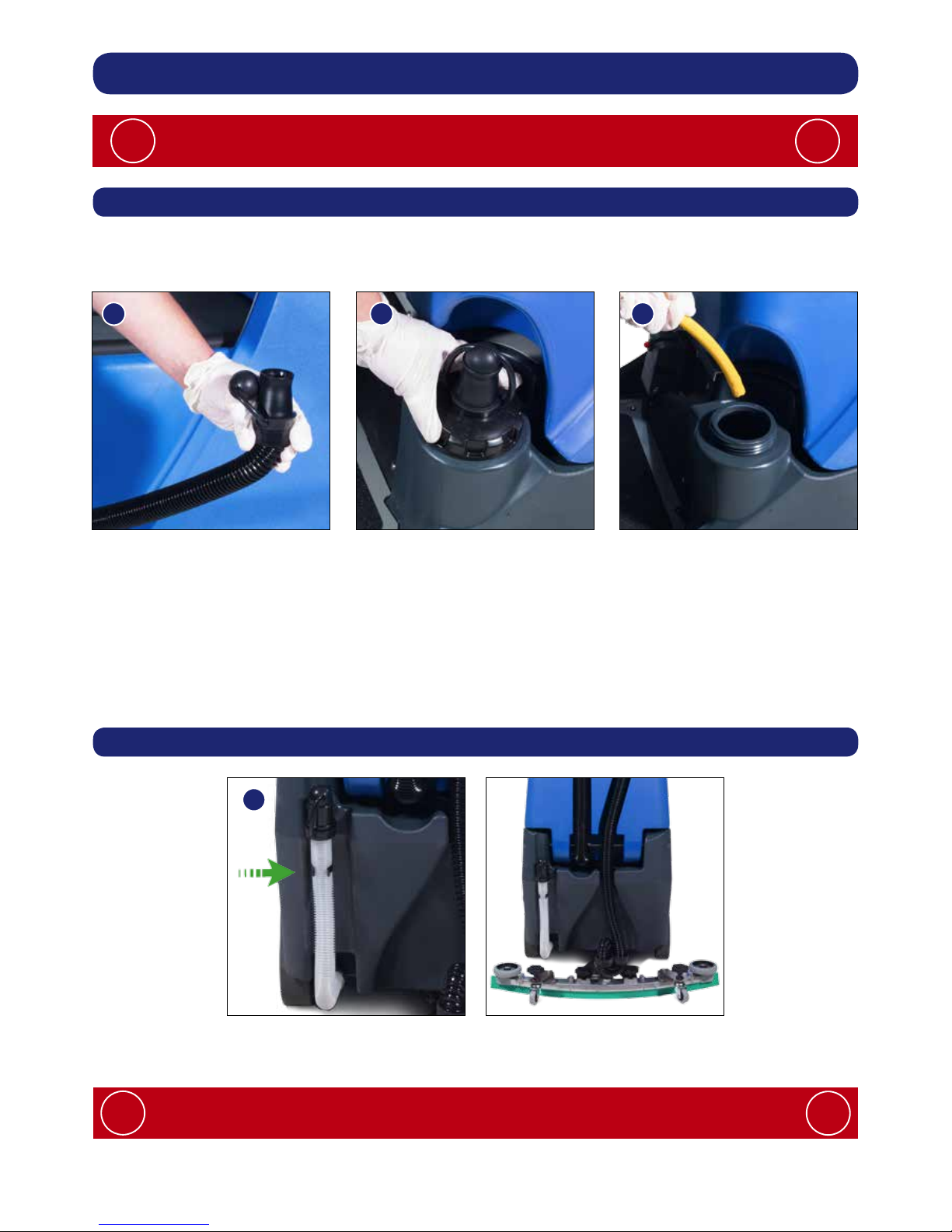
Filling the Clean Water Tank
Always ensure that the machine is switched off before making any adjustments
!
!
The TTB 2120 is equipped with a large capacity (21 US Gall) clean water tank, allowing for large
areas to be covered in a single ll.
To ll the clean water tank extend the Flexill hose, remove the rubber seal and ll from a suitable
water outlet (Fig.22). Replace seal and hose to original position when nished.
Alternatively unscrew the ller cap completely (Fig.23) and ll the tank using a hose or preferred
method (Fig.24).
Note: Great care must be taken to ensure that contaminants (leaves, hair, dirt, etc.) are not
allowed to enter the Clean water tank during the lling process. If using a bucket or similar,
ensure it is always clean and free from debris.
Fill Level Indicator
When lling the clean water tank, do not ll above the clean water tank emptying hose retaining
clip (Fig.25). This can be found at the rear of the machine.
222324
25
Full
If you need to access the batteries, make sure that the waste water tank is
empty before lifting.
!
!
11
= No Flow
= 0.13 gpm
= 0.26 gpm
= 0.39 gpm
= 0.52 gpm
= 0.79 gpm
Machine Operation
Important
Do not operate machine unless the operator manual has been read and fully understood.
!
!
The machine is now ready to be driven to the cleaning site (see the quick set-up guide if
necessary).
Before performing the cleaning operation, place out appropriate warning signs and sweep or
dust-mop the oor.
When you have arrived at the cleaning site, lower the Floor-tool (see page 8) and the brush
deck (see page 9).
Setting the Cleaning Controls
Insert the key into the on / off switch and
quarter-turn it clockwise to the ‘ON’ (1) position
(Fig.26).
The battery charge-level indicator will illuminate
(Fig.27).
Set the water ow rate as required, depending
on oor type and level of soiling.
Waste Water Tank Full
The vac shut off system tted to your machine
stops the airow when the top tank is full!
It does not shut the power off to the vac motor,
the vac motor will continue to run, but there is an
audible difference in the sound when the shut off
system operates.
See Page 16 for more details on checking and
cleaning the shut off system.
Always ensure that the oor is pre-swept and
relevant safety signs are displayed.
!
!
26
27
12
Machine Operation
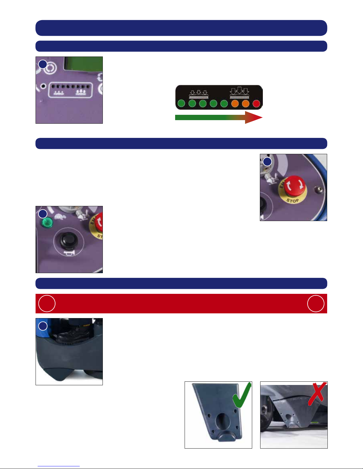
Brush Pressure
The machine is equipped with a brush-pressure load warning system
(Fig.28). As the load on the Brush increases the LEDs on the Load
Indicator will illuminate from left to right.
Note: The run-time of the machine may decrease if the load on the brushes is increased
The TTB 2120 is equipped with an electronic braking system.
Simply lift your foot from the accelerator and the machine will stop.
In an emergency, strike the emergency-stop button and the machine will
be disabled. To reset, turn emergency stop button clockwise (Fig.29).
After resetting the emergency stop button, to restart the machine,
turn the ignition key to the ‘Off’ then the ‘On’ position again.
The horn is located on the right-hand side of the operator control panel
(Fig.30).
Emergency Stop Button and Horn
Anti-tip System
The TTB 2120 is equipped with an Anti-tip system. If the operator
attempts to turn a corner when the machine is going at speed,
the machine will automatically slow down preventing the machine from
tipping over. Additionally the buffers at the front of the machine are
designed to prevent the machine tipping in the event of the operator
turning sharply (Fig.31).
Care must be taken to reduce speed when cornering or manoeuvring
!
!
28
29
30
31
The buffers are designed to be replaceable
when worn.
13
Machine Operation
Machine in Use
To operate, select forward, press the accelerator pedal.
Vacuum pick-up and water-ow will turn on if selected and the brush and
oor tool are in the lowered position, the machine will move forward.
Clean water is dispersed evenly via ‘THRU- FEED’ scrubbing brushes.
The waste water is then retrieved by the suction oor-tool (Fig.32).
Overlap each scrubbing path by 1/2” to ensure an even clean.
After stopping the Vac motor will run for a further 10 seconds to collect any
water left in the vacuum hose.
Do not operate the machine on inclines that exceed 11%.
!
!
If streaking occurs wipe
oor-tool blades clean (Fig.33).
On heavily soiled oors use a
‘double scrub’ technique.
First pre-scrub the oor with the
oor-tool in the raised position,
allow the chemicals time to
work then scrub the area a
second time with the oor-tool
lowered (Fig.34).
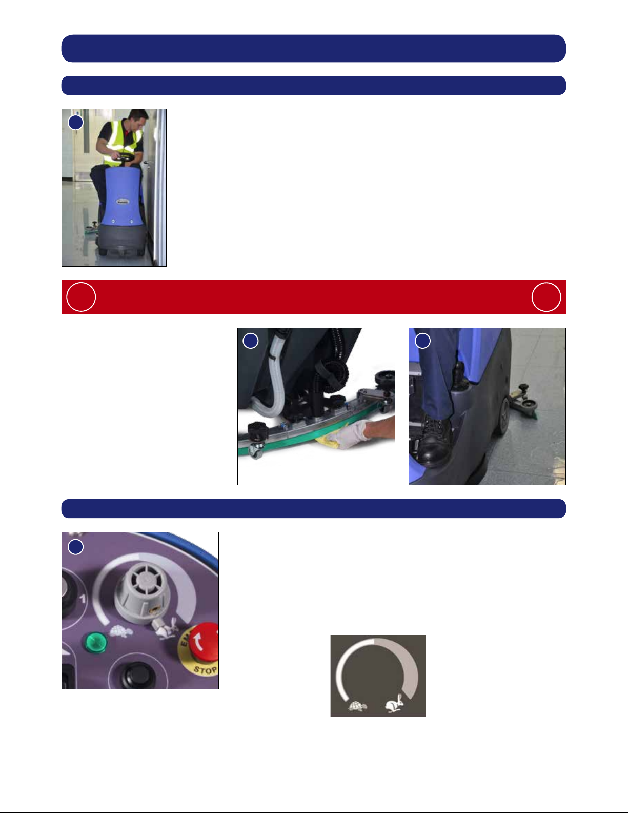
Maximum Speed Control
Use the maximum speed control knob and set desired traction
speed as required, depending on oor type and level of soiling
(Fig.35).
Keep speed setting within the white gradient on the dial for
optimum oor cleaning.
The grey gradient on the dial is for setting the transit speed.
32
34
33
35
Cleaning Transit
Once the Max speed has been set using the control knob on the
control panel, ne adjustments can be made using the variable
control speed pedal located on the right side of the footplate.
14
Machine Operation
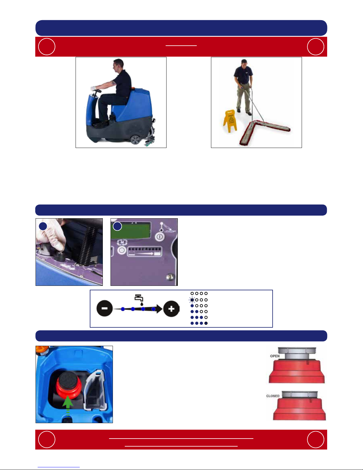
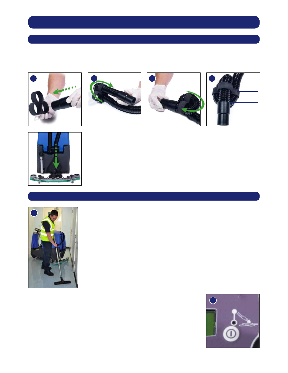
Hose U-bend Clip
Ret vacuum hose to the Floor-tool when nished.
Off-Aisle Cleaning Kit (Optional Extra Accessory ) 606182
Return the hose to the oor-tool once nished using the off-aisle facility.
The vacuum hose has a U-bend clip which creates a U-bend in the hose preventing water spillage
when the vacuum is switched off. If you need to remove the U-bend clip for any reason always
ensure it is retted correctly before you resume operation (Fig 36-39).
363738
39
40
41
The optional off-aisle cleaning kit gives added exibility to the operator.
The kit can be used to clean hard to reach / inaccessible areas (Fig 40).
Remove the Vacuum hose from the Floor-tool and attach to the Off-aisle kit.
To operate the vacuum, press the Off-aisle vacuum button on the
control panel.
Pressing the Off-aisle Button again will switch the vacuum off (Fig 41).
30mm
MAX
Note:
DO NOT push the vacuum hose onto the Floor-tool with the
Floor-tool in the raised position.
15
Machine Cleaning
Always ensure that the machine is switched off prior to any maintenance.
!
!
After use, empty waste-water tank using emptying hose and
ush-out with clean water.
Next remove oor-tool vacuum hose ensuring you remove the
U-bend clip and ush out with clean water.
Next empty clean water tank, using emptying hose and again
ush out with clean water.
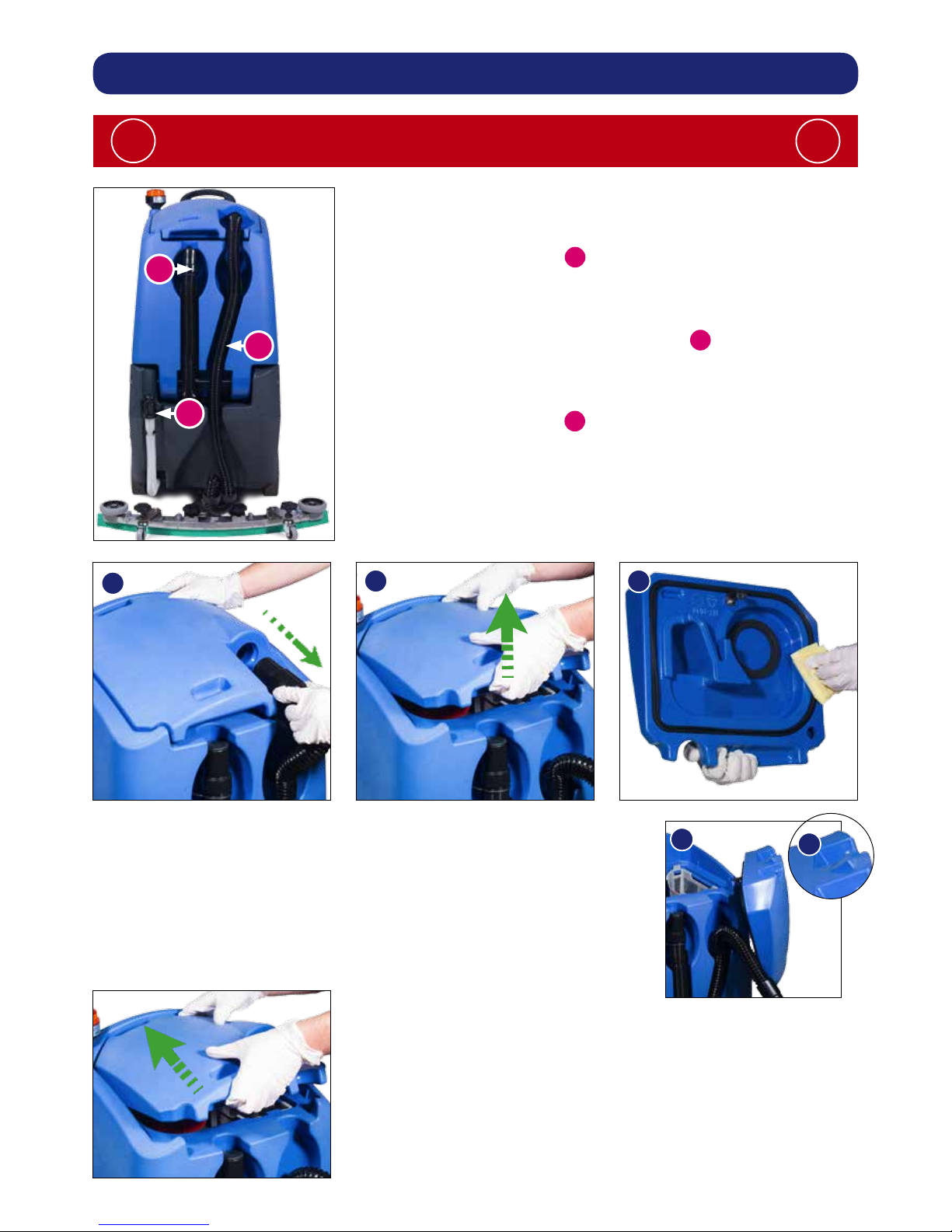
Before removing the separator, rst pull off the connected hose (Fig.42).
Remove the separator and rinse using clean water (Fig.43).
The separator also has a sealing-rubber which should be examined at
every clean-down (Fig.44).
Note: The separator can be hung from either side of the top tank
while you maintain the machine using the clip on the front of the lid.
(Fig.45).
A
B
C
A
B
C
42
43
44
45
When retting the separator make sure you engage the tab (A) at
the front of the separator BEFORE pushing the separator down.
Ret the vacuum hose.
A
16
Located in your waste water (top) tank is a vacuum shut off system, this prevents suction when the
waste water tank is full. It also prevents foam created by high-foaming detergents from entering
the motor. Sometimes the oat vents get clogged and blocked, clean to ensure correct operation
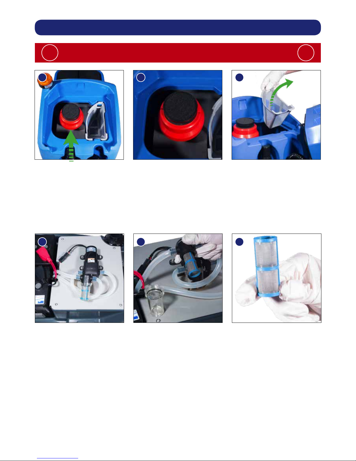
(Fig.46-47) reguarlly check and clean the air lter in the top of the assembly.
Remove debris basket lter and rinse using clean water, and ret (Fig 48).
IMPORTANT: If the debris basket is allowed to become clogged, vacuum performance can
deteriorate.
The clean-water tank lter is located to the front of the battery compartment, and should be
checked at regular intervals (Fig.49).
Lift the lter off of the cradle, unscrew the bottom and remove (Fig.50). taking care not to spill any
liquid on to the batteries. Rinse using clean water and ret (Fig 51).
Re-assemble the lter and ret into the lter cradle.
Note: Any Spills should be wiped up before tank is lowered.
Machine Cleaning
Always ensure that the machine is switched off prior to any maintenance.
!
!
464748
495051
 Loading...